Article

Field-Induced Transitions in Highly Frustrated SrHo2O4

1
Department of Physics, University of Warwick, Coventry CV4 7AL, UK
2
ISIS Pulsed Neutron Facility, Rutherford Appleton Laboratory, Harwell Oxford, Didcot OX11 0QX, UK
3
Institut Laue-Langevin, 6 Jules Horowitz, BP156, CEDEX 9, 38042 Grenoble, France
*
Authors to whom correspondence should be addressed.
Crystals 2019, 9(10), 488; https://doi.org/10.3390/cryst9100488
Submission received: 31 July 2019 / Revised: 12 September 2019 / Accepted: 17 September 2019 / Published: 22 September 2019
(This article belongs to the Special Issue Magnetic Field-induced Phase Transition)

Abstract

:
SrHo 2 O 4 is a geometrically frustrated magnet in which the magnetic Ho 3 + ions are connected through a network of zigzag chains and coupled by several competing interactions. The Ho 3 + ions show a pronounced Ising anisotropy at low temperatures, and the spins on the two crystallographically inequivalent magnetic sites point along orthogonal crystallographic axes. Using single-crystal neutron diffraction, we report on the development of complex and highly anisotropic short- and long-range magnetic order in SrHo 2 O 4 induced by an applied magnetic field. For H c , the diffuse scattering around the k = 0 positions is suppressed and above 0.5 T the spin structure for one of the Ho sites is long-range and ferromagnetic. For H b , planes of diffuse scattering at Q = ( h k ± l 2 ) are split by the field, and an up–up–down magnetic order associated with a 1/3-magnetisation plateau develops at 0.8 T. Further increasing the field above 1.2 T allows the second Ho site to also order in a long-range ferromagnetic structure.

1. Introduction

Competing magnetic interactions are studied in frustrated magnetism, and, when these are incompatible with the geometry of the lattice, systems can find it hard to establish a unique ground state. There are numerous examples of geometrically frustrated lattices, the most notable and studied being the triangular, pyrochlore, kagome, and hyper-kagome lattices. In this paper, we focus on SrHo 2 O 4 , one of the members of a large family of the SrLn 2 O 4 ( L n = lanthanide) compounds, which contain magnetic atoms arranged in zig-zag ladders and all of which demonstrate the typical signs of magnetic frustration—reduced ordering temperatures, coexistence of different ground states and high sensitivity to external perturbations, such as an applied magnetic field.
Initial magnetic susceptibility measurements on powder samples [1] of the SrLn 2 O 4 compounds have revealed a disparity in the Curie–Weiss constants, θ C W , and the lack of long-range order down to 1.8 K. In the SrLn 2 O 4 systems, all the atoms sit on the 4 c ( x , y , 0.25 ) positions in the Pnam crystal structure, and this allows for two slightly different octahedral environments of the rare-earth ions in a unit cell. Similarly to the famous cases of the spin ice behaviour found in some pyrochlore compounds [2] where the rare earth Ho and Dy ions behave like Ising spins, the magnetic ions in some SrLn 2 O 4 compounds, including SrEr 2 O 4 , SrDy 2 O 4 and SrHo 2 O 4 , also demonstrate strong single-ion anisotropy and could be described as Ising magnetic moments albeit with different easy-axis magnetisation directions for different sites.
In all the SrLn 2 O 4 systems, the magnetic ions form zigzag chains that run along the c-axis. The triangular ladders are magnetically equivalent to one-dimensional chains with first- and second-nearest-neighbour interactions, which could compete and lead to frustration. The chains of L n 3 + ions interconnect by forming a distorted honeycomb structure, a bipartite lattice made up of edge-sharing hexagons in the a–b plane, and the structure is shown in Figure 1. The inequivalent sites of the lanthanides are shown in red and blue.
Single crystals of the oxides have been grown [3], and several SrLn 2 O 4 compounds, where L n = Er [4,5], Dy [6,7], Gd [8] and Yb [9,10], have been studied in detail. All the crystals are magnetically highly anisotropic—for example, the electronic structure of Ho 3 + coupled with the crystalline electric field (CEF) allows it to display Ising like properties at low temperature, and the presence of low-lying CEF levels manifests as a large anisotropy in the Curie–Weiss temperatures for the three principal crystal directions of SrHo 2 O 4 ( θ CW is negative for a field applied along the a-axis and positive for a field along b-axis) [5]. A cusp in the susceptibility at 0.62 K suggests the presence of a phase transition, and there is also a noticeable difference between the data obtained on warming after cooling in field (FC) and the zero-field-cooled warming (ZFC) data [5]. The observed difference is due to incomplete spin order—the original partially ordered state does not recover if the field is cycled up and then down. The application of a magnetic field along the principal crystal axes of all of the SrLn 2 O 4 compounds induces a variety of in-field transitions. For SrHo 2 O 4 , the a-axis is a hard magnetisation direction, and at low temperatures only a single field-induced transition is seen for H c [5]. A magnetisation plateau (centred around 0.8 T at 0.5 K) at approximately one third of the saturation magnetisation value (2.5 μ B ) can be seen when the field is applied along the b-axis [5]. Such plateaux are usually a sign of field-induced stabilisation of a collinear two-spins-up–one-spin-down (uud) magnetic structure, in which on each triangle of spins, two are pointing up along the field and the third spin is pointing down anti-parallel to the field direction [11,12,13].
Single crystal neutron diffraction data collected in zero field show that down to 0.05 K all of the scattering from SrHo 2 O 4 is short-range in nature, and, more unusually, the spins on the two magnetic sites point along orthogonal crystallographic axes (SrHo 2 O 4 itself shows no chemical instability or phase separation) [14]. It is likely that the CEF and single ion anisotropy are responsible for the magnetic moments on the two crystallographically inequivalent sites pointing along two different axes. In the ( h k 0 ) plane, diffuse magnetic scattering rapidly appears below 0.7 K around positions with the propagation vector k = 0 . A second type of diffuse scattering gradually appears as planes of scattering intensity at ( h k ± l 2 )—showing that the unit cell for this magnetic structure is doubled along the c-axis. These planes are seen as “rods” of scattering intensity in both the ( h 0 l ) and ( 0 k l ) planes in reciprocal space at Q = ( 00 1 2 ) and symmetry related positions, even at 4.5 K [14]. Therefore, the second type of short-range order present in this material is one-dimensional in real space, and it persists over a wider temperature range—the onset of these correlations may also be observed with bulk heat capacity measurements as the broad peak around ∼3 K. The coexistence of the two types of diffuse scattering in SrHo 2 O 4 is likely to be the result of the presence of two crystallographically inequivalent sites for Ho 3 + in the unit cell. Other members of the SrLn 2 O 4 series, SrEr 2 O 4 and SrDy 2 O 4 , also show the coexistence of two markedly different types of magnetic ordering at low-temperatures [7,15,16].
To investigate the field dependent behaviour of the two spin structures seen in single crystal SrHo 2 O 4 samples in zero applied field, we have followed the field evolution of the neutron diffraction patterns of the ( h k 0 ) and ( h 0 l ) scattering planes. The results of our measurements show that, at low temperatures, when a field is applied along the c-axis, the diffuse magnetic scattering that appears around positions with the propagation vector k = 0 in the ( h k 0 ) plane is suppressed, and that a phase transition to a fully polarised structure occurs above μ 0 H = 0.4 T. Remarkably, when the magnetic field is reversed back down to zero, the original scattering pattern does not reappear and can only be restored by warming up to temperatures above 0.7 K, and cooling back down in zero field.
The changes in the behaviour of the one-dimensional spin component of the SrHo 2 O 4 magnetic structure were investigated for a field applied along the b-axis, for which a magnetisation plateau appeared to be stabilised. At low fields, planes of scattering intensity at ( h k ± l 2 ) are visible, similar to those observed during the zero-field experiments, but as the field is increased, the correlation lengths increase along both h and k, and a new diffuse scattering profile with non-integer l indices appears. The spins that participate in this structure are antiferromagnetically coupled and are pointing along the b direction. Even larger fields suppress all of the diffuse scattering and new Bragg peaks are seen in the neutron cross-section. However, by applying a field along the b direction, the diffuse scattering intensity around the k = 0 positions remains unchanged.

2. Experimental Details

Large volume single crystals of SrHo 2 O 4 were grown using the floating zone method, with details of the procedure reported elsewhere [3]. The samples were aligned using the backscattering Laue technique and cut perpendicular to the principal crystal axes, within an estimated accuracy of 2 for the D7 measurements and within 1 for the WISH experiment. Two different 0.9 g samples of SrHo 2 O 4 , fixed to oxygen free copper sample holders using Kwikfill resin, were used during the D7 and WISH experiments, with equivalent sample mountings used for background measurements.
Neutron diffraction measurements in the ( h k 0 ) scattering plane were made using the cold neutron WISH instrument [17] at the ISIS facility (Rutherford Appleton Laboratory, Didcot, UK) at 0.055 K in a range of magnetic fields from 0.0 to 2.5 T. WISH is equipped with a large array of position sensitive 3 He detectors giving substantial Q-space coverage with good resolution.
The diffuse scattering spectrometer D7 [18,19,20] (at the Institut Laue-Langevin (ILL) in Grenoble, France) was used to collect neutron scattering data for the ( h 0 l ) scattering plane at 0.06 K in an applied field range of 0.0 to 2.0 T. The D7 instrument is equipped with 132 3 He detectors which are each separated by 1 . Throughout the experiment, cold neutrons monochromated to a wavelength of 3.1 Å were used, resulting in Q-space coverage of 0.14 to 3.91 Å 1 . An amorphous quartz standard was used to normalise the polarisation efficiency and a vanadium standard was used to normalise the detector efficiency of the instrument. Scans were performed in which the crystal was rotated about the vertical axis in steps of 1 . During field dependent experiments, only the Z polarisation non-spin-flip (NSF) and spin-flip (SF) datasets were collected, since the magnet cannot be rotated to perform the full XYZ polarised measurement. The reciprocal space maps were constructed using standard D7 data reduction functions.

3. Results and Discussion

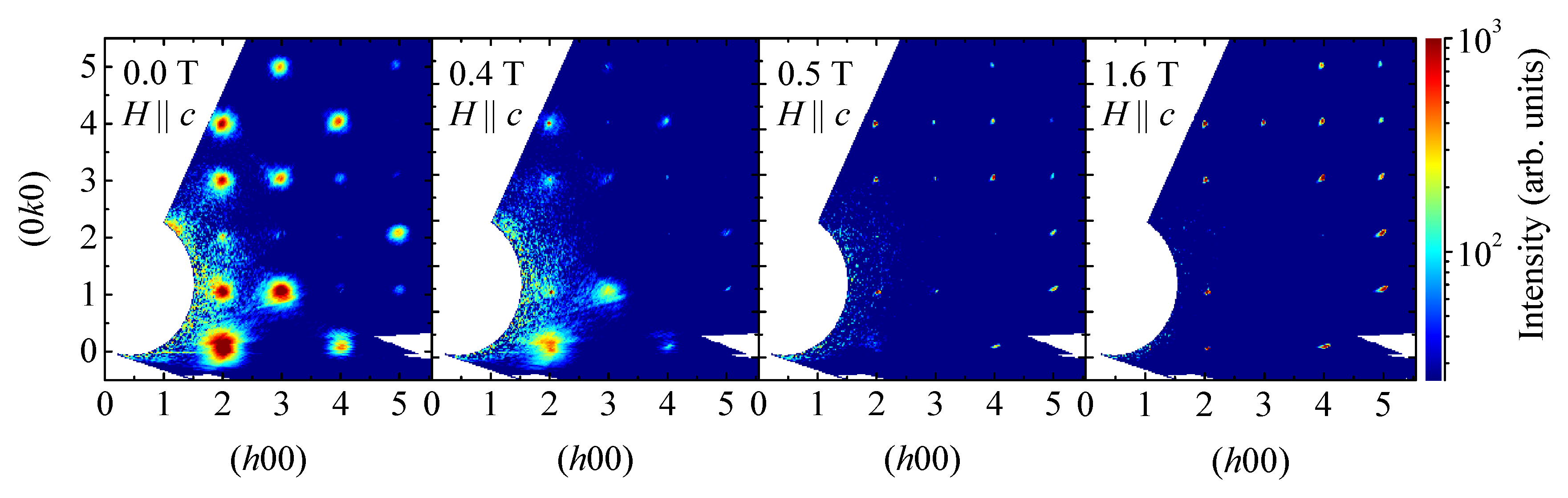
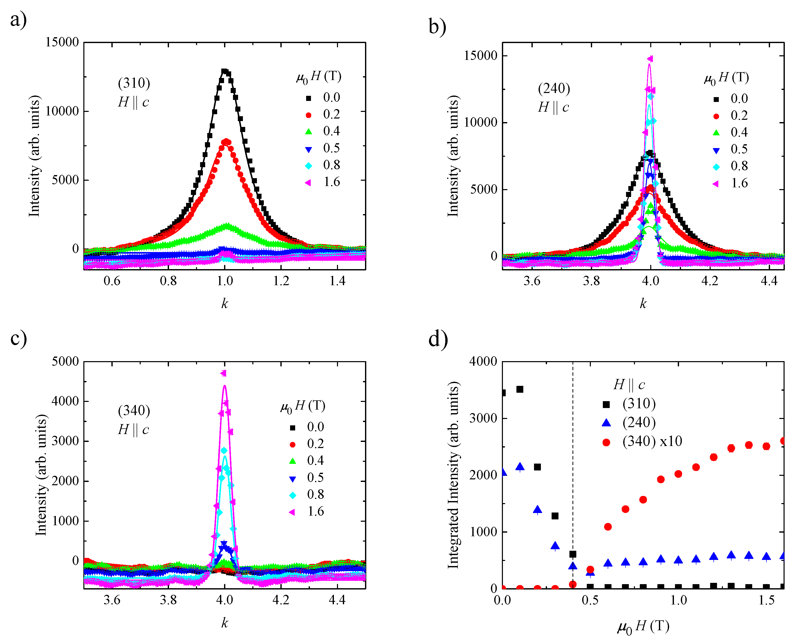
3.1. Diffraction Measurements (hk0) Plane

Measurements of the field dependence of the scattering in the ( h k 0 ) plane from SrHo 2 O 4 , at 0.055 K and in a magnetic field range of 0 to 1.6 T applied along the c-axis, were made using the WISH diffractometer. Figure 2 shows the observed magnetic scattering intensity (which was found by subtracting a 1.5 K background, collected in zero applied field, from the low-temperature datasets). To a first approximation, it was assumed that the background and the nuclear peaks do not have a pronounced temperature and field dependence. A small oversubtraction which can be seen in Figure 3a–c is most likely due to paramagnetic scattering being reduced by progressively higher values of the applied field. It is apparent that, when a field is applied along the c-axis, the diffuse magnetic scattering that appears around the k = 0 positions in the ( h k 0 ) plane is suppressed, and for some reflections a new Bragg component appears above μ 0 H = 0.4 T that suggests that a transition occurs to a high field state. These new peaks are consistent with peaks which would appear if only half of the Ho 3 + sites ordered ferromagnetically, which can be calculated by finding the positions of the nuclear peaks from SrHo 2 O 4 if either one or the other of the crystallographically inequivalent sites was not present. The change in behaviour above 0.4 T for fields applied along the c-axis in SrHo 2 O 4 was also observed as a clear peak in the low temperature magnetisation measurements.
Datasets to illustrate the field evolution of the magnetic scattering intensity for different reflections in the ( h k 0 ) plane are presented in Figure 3a–c. Reflections such as (310) lose all of their diffuse intensity upon increasing the field up to 0.5 T, and subsequent increases of the applied field do not change their magnitude; see Figure 3a. The diffuse scattering is suppressed by a field of 0.5 T for a lot of the magnetic reflections, with peaks such as (240) shown in Figure 3b initially losing intensity, but then developing strong (and likely ferromagnetic) components. Reflections such as (340), whose field dependence is shown in Figure 3c, did not have any diffuse magnetic intensity in zero field, and only develop Bragg intensities in applied fields above 0.4 T. The intensities of the new Bragg peaks that are stabilised by an applied field do not saturate, so it can be assumed that the spins are not yet completely aligned by the field. From magnetisation measurements, it is clear that the saturation value for H c is above 7 T (the highest applied field that SrHo 2 O 4 has been measured in). Throughout, the diffuse scattering features have been fit using a Lorentzian distribution, and the ferromagnetic peaks have been fit using a Gaussian distribution. From the fits to the data, it can be seen that the Lorentzian component decreases, and the correlation lengths associated with the diffuse scattering features go to zero (not shown). The field dependence of the magnitude of the integrated magnetic intensity for the different reflections is summarised in the bottom left panel of Figure 3.
The one-dimensional structure does not appear to be affected by applying the field along the c-axis. The highest value of the applied field used during the experiment (1.6 T) is not enough to fully align these spins along the field direction, and the situation is likely to be similar to SrEr 2 O 4 [4], where it is shown that saturation of the moments is not achieved even in fields of 27 T. The application of the field along the c-axis is not a reversible operation, as demonstrated in Figure 4, where data are shown in zero field before any field is applied and after going to high field before remeasuring at 0 T. The zero field diffuse scattering intensity profile is readily recovered, however, if the sample is warmed up above 0.7 K, and cooled back down in zero field. This behaviour in an applied field can be related to the single crystal susceptibility experiments where a difference can be seen between ZFC and FC measurements [5].

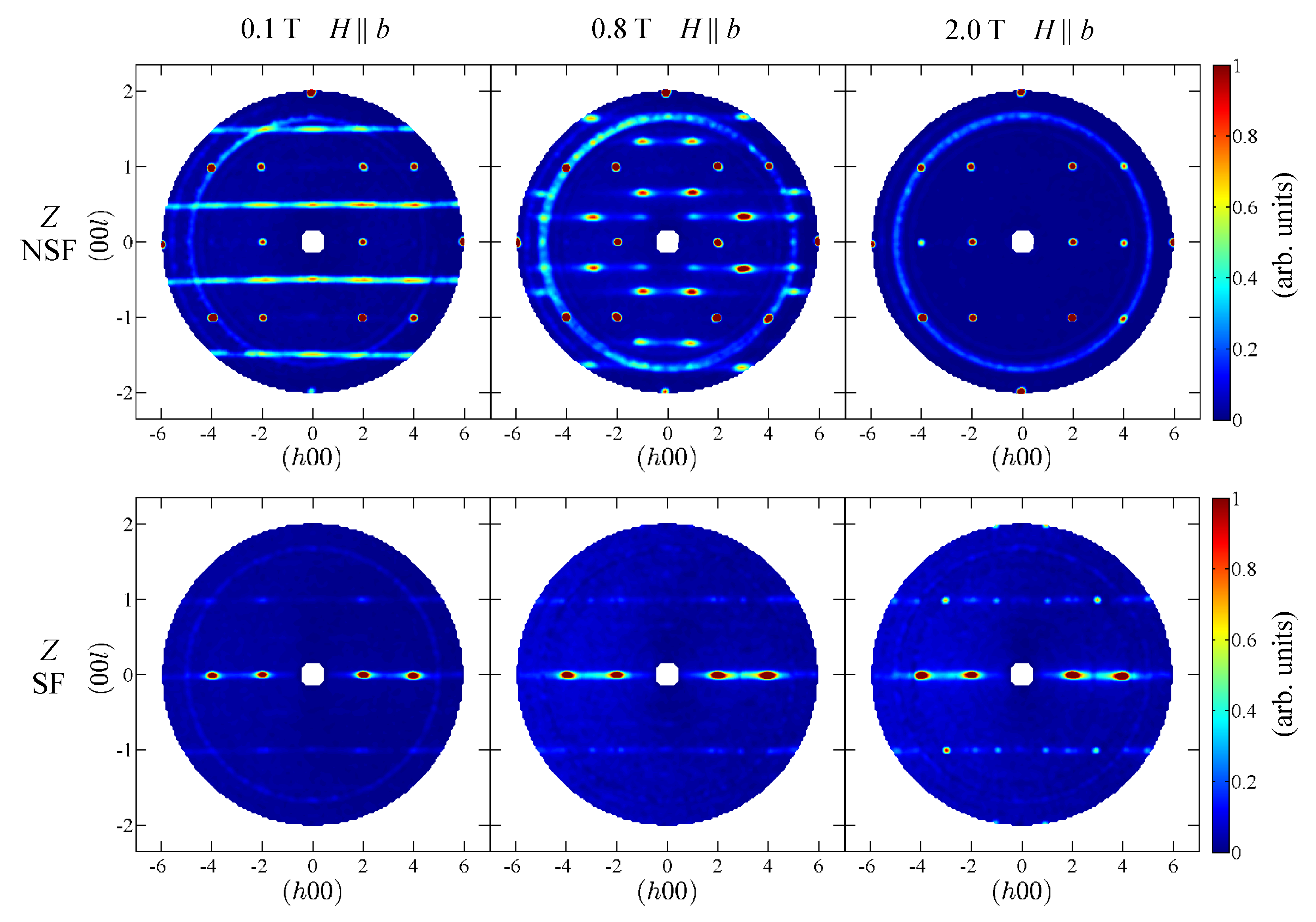
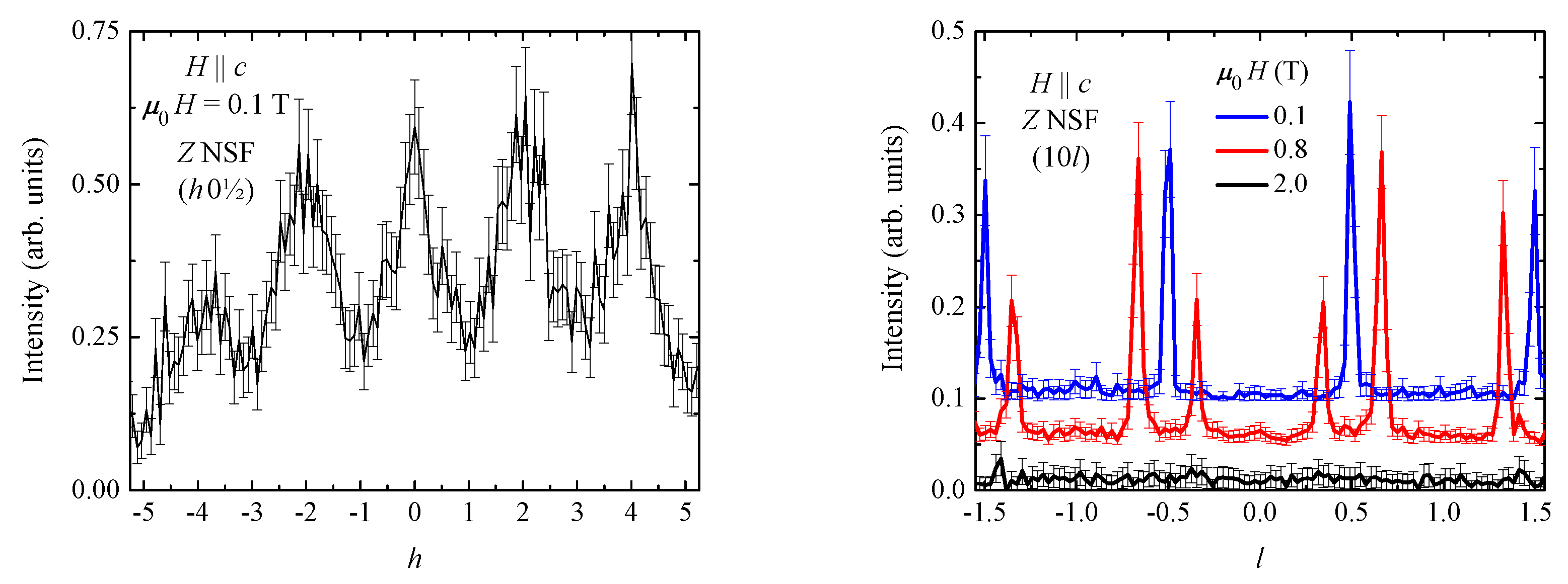
3.2. Diffraction Measurements (h0l) Plane

From the lowest temperature magnetisation measurements on a single crystal SrHo 2 O 4 sample, it is conjectured that an up–up–down collinear spin state appears to be stabilised when a field of around 0.8 T is applied along the b-axis [5]. This state can be inferred from the location of the plateau observed in M ( H ) , a minimum in d M / d H , at a third of the value expected for the fully saturated moment. Thus, in order to investigate the field induced changes to the one-dimensional diffraction pattern from SrHo 2 O 4 , polarised neutron scattering measurements were performed using the D7 instrument [18,19,20]. The polarised neutron experiments were configured to measure two independent components of the scattering function, here called the non-spin-flip and spin-flip channels. The Z polarisation direction in our measurements is normal to the scattering plane, and hence the sum of Z NSF and Z SF measurements is what would be observed in unpolarised neutron experiments. The field was applied along the b-axis (which also coincides with the Z polarisation direction) and the scattering in the ( h 0 l ) plane was measured at 125 mK in the magnetic field range of 0.1 to 2.0 T. The top and bottom panels of Figure 5 show the scattering intensity in the Z polarised NSF and SF channels in applied fields of 0.1, 0.8 and 2.0 T. The background that can be attributed to scattering from the cryomagnet, dilution fridge and the copper sample holders used in the experiment was measured in 0.1 T. The background correction appears to work less well for higher scattering vectors, which means that there are some residual powder lines from the copper in the diffraction patterns in Figure 5.
As in the zero field measurements, in low applied fields of 0.1, 0.3 and 0.6 T, there are rods of scattering intensity at ( 00 1 2 ) and symmetry related positions in the Z NSF measurement. The experiment is directly comparable to the zero-field data—the only difference is that this time the sample has been FC and the data collected in a small field of 0.1 T. Thus, the structure of the magnetic scattering is similar—again the pronounced Q-dependence to the scattering intensity, where maxima of intensity occurring near the integer values of h can be seen, as shown in the left panel of Figure 6, but the magnetic scattering is not as intense as in the zero field pattern. No extra magnetic features due to the ( h k ± l 2 ) planes are observed in the spin–flip channel, and only the diffuse scattering intensity along ( h 00 ) is clearly visible in the measurements, which is due to the k = 0 type structure.
By 0.8 T, the rods split into “spots”, for example at ( 10 1 3 ) and ( 10 2 3 ), and symmetry related positions, as shown in the right panel of Figure 5. This scattering pattern for the up–up–down spin state is also visible in 1.0 T; however, by 1.2 T, the diffuse “spots” have lost some intensity. Figure 6 shows the cuts through ( 10 l ) in three fields along the l-direction. Upon increasing the applied field above 1.2 T (not shown), all of the diffuse scattering disappears and only intense new Bragg peaks are measurable in both the Z NSF and Z SF datasets. For example, in the 2.0 T dataset shown in Figure 5, a new Bragg spot at (400) appears in the Z NSF measurement. Overall, there is good correlation between what was seen in the neutron scattering pattern and the critical field positions that were expected from bulk magnetisation measurements for the field applied along the b-axis of SrHo 2 O 4 [5]. It should be noted that, for the diffuse scattering intensity due to the k = 0 type structure (seen in the Z SF channel), there is relatively little difference in the scattering pattern for all applied fields compared to zero field measurements.
On the D7 instrument, access is mostly possible to the ( h 0 l ) plane in reciprocal space (with only a ±4 degrees out-of-plane angle [20]). Therefore, complementary measurements with unpolarised neutrons using the E2 instrument [21] at HZB were also performed. E2 allows for a significant out-of-plane coverage; however, no new information on the changes to the magnetic scattering when H b compared to the D7 results was obtained. The nature of the diffuse magnetic scattering can be inferred from the Z polarisation direction NSF and SF data. In the one-dimensional magnetic structure and in the uud state, all the intensity is in the Z NSF component and thus all of the spins lie parallel with the b-axis, but, in the high-field state, new Bragg peaks appear in both the Z NSF and Z SF measurements.
Finally, it is interesting to compare the diffraction patterns of the field dependence of the scattering from SrHo 2 O 4 for H b (along which a plateau in magnetisation is stabilised) to those observed in SrDy 2 O 4 [7]. In both compounds, the initially broad diffuse scattering features seen in zero field are significantly enhanced and sharpened by the applied field. The diffraction patterns look similar; however, the field-induced non-integer peaks corresponding to the stabilisation of the uud state appear in different positions in reciprocal space and therefore must correspond to different magnetic structures. Given that in the isostructural SrEr 2 O 4 compound a magnetisation plateau is also stabilised for a field applied along the a-axis [5], it would be interesting to eventually compare and contrast the details of the up–up–down spin states induced by the field in all three of these compounds, as well as in other SrLn 2 O 4 materials.

4. Conclusions

We have performed low-temperature single-crystal neutron diffraction measurements in order to investigate the in-field behaviour of SrHo 2 O 4 and to determine its magnetic phase diagram. We have observed the field-evolution of the diffraction patterns in two orthogonal scattering planes, ( h k 0 ) and ( h 0 l ) . In both geometries, the main effect of an applied field is seen in the evolution of the diffuse scattering. The findings can be readily correlated with the single crystal magnetisation data collected at low temperatures.
When the field is applied along the c-axis, only one transition is observed, and the diffuse scattering around the k = 0 positions seen in zero field is suppressed, and even larger fields induce long-range order in the system. The observed transition is essentially an antiferromagnetic to ferromagnetic rearrangement of the magnetic moments on one of the Ho sites.
When the field is applied along the b-axis where an uud magnetisation plateau appears, the planes of one-dimensional scattering in reciprocal space at Q = ( 00 1 2 ) and symmetry related positions are split into a new diffuse phase for a range of values of the applied field. The field-induced peaks can be indexed as ( h k l 3 ) ; they are much sharper and better defined than the zero-field diffuse features, suggesting that the uud phase has a significant correlation length. Eventually, as the field strength is increased further, this uud phase is suppressed and new Bragg peaks appear in the diffraction pattern. For this direction of an applied field, the observed transition is also from an antiferromagnetic to ferromagnetic rearrangement of the moments on another of the Ho sites, but through a relatively wide and stable up–up–down spin phase.

Author Contributions

G.B. grew a single crystal sample of SrHo 2 O 4 . O.Y. prepared the samples, performed neutron diffraction experiments and analysed the data with the help from P.M., D.D.K., and A.R.W. O.A.P. conceived the work and supervised the project. O.Y. and O.A.P. prepared the manuscript with the contributions from all the authors.

Funding

This work was funded by EPSRC, UK through Grants EP/I007210/1 and EP/M028771/1. The authors would like to thank T. E. Orton for the valuable technical support and acknowledge the work and dedication of the sample environment teams at ISIS and ILL.

Conflicts of Interest

The authors declare no conflict of interest.

References

  1. Karunadasa, H.; Huang, Q.; Ueland, B.G.; Lynn, J.W.; Schiffer, P.; Regan, K.A.; Cava, R.J. Honeycombs of triangles and magnetic frustration in SrL2O4 (L = Gd, Dy, Ho, Er, Tm, and Yb). Phys. Rev. B 2005, 71, 144414. [Google Scholar] [CrossRef]
  2. Bramwell, S.; Gingras, M. Spin Ice State in Frustrated Magnetic Pyrochlore Materials. Science 2001, 294, 1495. [Google Scholar] [CrossRef] [PubMed]
  3. Balakrishnan, G.; Hayes, T.J.; Petrenko, O.A.; McK Paul, D. High quality single crystals of the SrR2O4 family of frustrated magnets. J. Phys. Condens. Matter 2009, 21, 012202. [Google Scholar] [CrossRef] [PubMed]
  4. Petrenko, O.A.; Balakrishnan, G.; Wilson, N.R.; de Brion, S.; Suard, E.; Chapon, L.C. Low-temperature magnetic ordering in SrEr2O4. Phys. Rev. B 2008, 78, 184410. [Google Scholar] [CrossRef]
  5. Hayes, T.J.; Young, O.; Balakrishnan, G.; Petrenko, O.A. Magnetisation Studies of Geometrically Frustrated Antiferromagnets SrLn2O4, with Ln = Er, Dy, and Ho. J. Phys. Soc. Jpn. 2012, 84, 024708. [Google Scholar] [CrossRef]
  6. Cheffings, T.H.; Lees, M.R.; Balakrishnan, G.; Petrenko, O.A. Magnetic field-induced ordering in SrDy2O4. J. Phys. Condens. Matter 2013, 25, 256001. [Google Scholar] [CrossRef] [PubMed]
  7. Petrenko, O.A.; Young, O.; Brunt, D.; Balakrishnan, G.; Manuel, P.; Khalyavin, D.D.; Ritter, C. Evolution of spin correlations in SrDy2O4 in an applied magnetic field. Phys. Rev. B 2017, 95, 104442. [Google Scholar] [CrossRef]
  8. Young, O.; Balakrishnan, G.; Lees, M.R.; Petrenko, O.A. Magnetic properties of geometrically frustrated SrGd2O4. Phys. Rev. B 2014, 90, 094421. [Google Scholar] [CrossRef]
  9. Quintero-Castro, D.L.; Lake, B.; Reehuis, M.; Niazi, A.; Ryll, H.; Islam, A.T.M.N.; Fennell, T.; Kimber, S.A.J.; Klemke, B.; Ollivier, J.; et al. Coexistence of long- and short-range magnetic order in the frustrated magnet SrYb2O4. Phys. Rev. B 2012, 86, 064203. [Google Scholar] [CrossRef]
  10. Petrenko, O.A. Low-temperature magnetism in the honeycomb systems SrLn2O4. Low Temp. Phys. 2014, 40, 106. [Google Scholar] [CrossRef]
  11. Nishimori, H.; Miyashita, S. Magnetization Process of the Spin-1/2 Antiferromagnetic Ising-Like Heisenberg Model on the Triangular Lattice. J. Phys. Soc. Jpn. 1986, 55, 4448. [Google Scholar] [CrossRef]
  12. Chubukov, A.V.; Golosov, D.I. Quantum theory of an antiferromagnet on a triangular lattice in a magnetic field. J. Phys. Condens. Matter 1991, 3, 69. [Google Scholar] [CrossRef]
  13. Honecker, A.; Schulenburg, J.; Richter, J. Magnetization plateaus in frustrated antiferromagnetic quantum spin models. J. Phys. Condens. Matter 2004, 16, S749. [Google Scholar] [CrossRef]
  14. Young, O.; Wildes, A.R.; Manuel, P.; Ouladdiaf, B.; Khalyavin, D.D.; Balakrishnan, G.; Petrenko, O.A. Highly frustrated magnetism in SrHo2O4: Coexistence of two types of short-range order. Phys. Rev. B 2013, 88, 024411. [Google Scholar] [CrossRef]
  15. Hayes, T.J.; Balakrishnan, G.; Deen, P.P.; Manuel, P.; Chapon, L.C.; Petrenko, O.A. Coexistence of the long-range and short-range magnetic order components in SrEr2O4. Phys. Rev. B 2011, 84, 174435. [Google Scholar] [CrossRef]
  16. Malkin, B.Z.; Nikitin, S.I.; Mumdzhi, I.E.; Zverev, D.G.; Yusupov, R.V.; Gilmutdinov, I.F.; Batulin, R.; Gabbasov, B.F.; Kiiamov, A.G.; Adroja, D.T.; et al. Magnetic and spectral properties of the multisublattice oxides SrY2O4:Er3+ and SrEr2O4. Phys. Rev. B 2015, 92, 094415. [Google Scholar] [CrossRef]
  17. Chapon, L.C.; Manuel, P.; Radaelli, P.G.; Benson, C.; Perrott, L.; Ansell, S.; Rhodes, N.; Raspino, D.; Duxbury, D.; Spill, E.; et al. Wish: The new powder and single crystal magnetic diffractometer on the second target station. Neutron News 2011, 22, 22. [Google Scholar] [CrossRef]
  18. Schärpf, O.; Capellmann, H. Structural and magnetic investigations of a La2CuO4 single crystal with polarization analysis. Z. Phys. B 1990, 80, 253. [Google Scholar] [CrossRef]
  19. Schärpf, O.; Capellmann, H. The XYZ-Difference Method with Polarized Neutrons and the Separation of Coherent, Spin Incoherent, and Magnetic Scattering cross Sections in a Multidetector. Phys. Status Solidi 1993, 135, 359. [Google Scholar] [CrossRef]
  20. Stewart, J.R.; Deen, P.P.; Andersen, K.H.; Schober, H.; Barthelemy, J.F.; Hillier, J.M.; Murani, A.P.; Hayes, T.; Lindenauc, B. Disordered materials studied using neutron polarization analysis on the multi-detector spectrometer, D7. J. Appl. Crystallogr. 2009, 42, 69. [Google Scholar] [CrossRef]
  21. Young, O.; Glavatskyi, I.; Petrenko, O.A. HZB Experimental Report PHY-01-3098: Magnetic Phase Diagram of Geometrically Frustrated SrHo2O4. In BER II Experimental Reports 2012; Helmholtz-Zentrum Berlin: Berlin, Germany, 2013. [Google Scholar]
Figure 1. Magnetic sublattice of SrHo 2 O 4 , with the two crystallographically inequivalent positions of the rare earth ions shown in different colours. When viewed in the a–b plane, honeycombs of the Ho 3 + ions are visible. Zigzag chains running along the c-axis connect the honeycomb layers and give rise to geometric frustration. The box indicates the dimensions of the unit cell.
Crystals 09 00488 g001
Figure 2. Magnetic contribution to the scattering from SrHo 2 O 4 in the ( h k 0 ) plane at 0.055 K in several applied fields. The magnetic component was isolated by subtracting a 1.5 K background from the low-temperature single crystal neutron diffraction data collected using WISH, ISIS [17].
Crystals 09 00488 g002
Figure 3. (ac) Field dependence of the magnetic scattering intensity of the (310), (240) and (340) reflections from SrHo 2 O 4 , isolated by subtracting a 1.5 K background measured in zero field. Data were collected using the WISH instrument, ISIS. For the (310) reflection, the nuclear component is practically zero, so only magnetic scattering is seen at low temperatures, and the data have been fit using a Lorentzian distribution. The (240) reflection has a strong nuclear component, and here the data have been fit using a Lorentzian distribution for μ 0 H 0.4 T, and using a Gaussian distribution for μ 0 H 0.5 T. For both reflections, the diffuse scattering that is seen in zero field gets suppressed upon the application of higher fields, and is completely gone by 0.5 T. For (240) above 0.5 T, a new magnetic Bragg-like component develops. Originally, (340) does not have a magnetic component, but, in applied fields above 0.5 T, a large component consistent with a ferromagnetic phase starts to develop, and the data have been fit using a Gaussian distribution; (d) The summary of the field dependence of the integrated magnetic intensities of the three different reflections from SrHo 2 O 4 at 0.05 K.
Crystals 09 00488 g003
Figure 4. Scattering intensity of (left) the (310) and (right) the (240) reflections from SrHo 2 O 4 in zero applied field. The original intensity (before switching on the field), is entitled “up”, and then the intensity measured after going to 1.6 T before setting the field back to 0 T, is called “down”. The diffuse scattering profile never recovers, and this can also be seen as a difference in the ZFC and FC susceptibility measurements [5].
Crystals 09 00488 g004
Figure 5. Intensity maps of the scattering from SrHo 2 O 4 at different fields, collected at 125 mK using the D7 instrument at the ILL. In three applied fields along the b-axis of 0.1, 0.8 and 2.0 T, the top row panels show the Z polarisation non-spin-flip (NSF) scattering intensity and bottom row panels show the Z polarisation spin-flip (SF) scattering contribution. The sample was cooled in field, so at 0.1 T the rods of scattering due to the ( h k ± l 2 ) planes are less intense, but their structure shows relatively little difference compared to the scattering seen in the zero field measurements. By 0.8 T, the rods split into “spots”, for example at ( 10 1 3 ) and ( 10 2 3 ), and symmetry related positions. By 2.0 T, all of the diffuse scattering due to the low-dimensional magnetic structure disappears and only intense Bragg spots are seen in the diffraction pattern, with for example a new Bragg spot at (400) in the Z NSF measurement. This field dependence closely follows what was expected from the bulk magnetisation measurements. The diffuse magnetic peaks associated with the k = 0 structure are also visible in the Z SF measurement, and these do not appear to be affected by the field applied along the b-axis. The backgrounds were measured in 0.1 T, and thus the subtraction at higher fields is not perfect so powder “rings” due to the cryomagnet and the sample environment can be seen in the data.
Crystals 09 00488 g005
Figure 6. (Left) Q-dependence of the intensity of the magnetic diffuse scattering from SrHo 2 O 4 along ( h 0 1 2 ) in 0.1 T, extracted from the Z polarisation NSF measurement. For the rods of scattering at ( 00 1 2 ) and symmetry related positions in 0.1 T, there is relatively little difference in the scattering compared to zero field measurements—the scattering is most intense at even integer values of h. (Right) Intensity of the magnetic diffuse scattering from SrHo 2 O 4 along ( 10 l ) in three applied fields, extracted from the Z NSF measurements, with the curves offset for clarity. At 0.1 T, there are rods of scattering intensity at ( 00 l 2 ) and symmetry related positions, which by 0.8 T are split into “spots” of diffuse intensity at ( 10 1 3 ) and ( 10 2 3 ), where the intensity at ( 10 2 3 ) is twice that at ( 10 1 3 ). Along ( 10 l ), no new Bragg features appear and all of the diffuse scattering is gone in an applied field of 2.0 T.
Crystals 09 00488 g006

