Abstract
A contemporary apparatus with radiation (light) heating for growth of single crystals of refractory oxides and metals is described. To reduce the dissociation or evaporation of the melt or crystal components, the growth process was carried out in oxygen or an alternative gas at pressures up to 100 bar. The annealing system applied directly in the growth process at 1650 °C under O2 pressure and at temperatures up to 2500 °C under protective gas flow, allows the obtaining of large and perfect single crystals. Many single crystals of oxide materials, including incongruently melting substances, such as Y3Fe5O12, Gd3Fe5O12, BaFe12O19, SrFe12O19, BaFe12-x AlxO19, and many others have been grown, and much more could be grown.
1. Introduction
The light focused by mirrors was first used for growing single crystals of oxide and metallic materials in the work of Poplawsky [1] and Kooy [2]. Many optical schemes with concentrators for these purposes have been proposed (Figure 1).
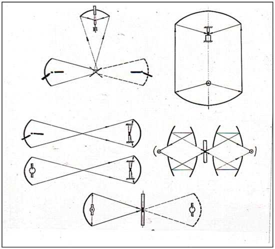
Figure 1.
Optical schemes of floating zone crystal growth.
Crystal growth of refractory oxides by the floating zone technique was introduced by Halden [3], O’Bryan [4], Fairholme [5], Field and Wagner [6], and Medvedev and Balbashov [7]. Employed bi-ellipsoidal and bi-paraboloidal apparatus arrangements used a carbon arc or short arc xenon lamp as radiation sources. Okada [8] and Kitazawa [9] have reported an interesting construction of the apparatus for floating zone melting having a water-cooled metal reflector in the form of a full rotation ellipsoid and halogen or xenon arc lamp. A number of single oxide crystals have been grown in this apparatus, in particular, orthoferrite, yttrium-iron garnets [10], Y2O3 [11], titanates [12], etc. An optical concentrator of the multi-ellipsoidal form used by Eyer et al. [13] in a small-size floating zone apparatus designed for the growth of single crystals in space. In 1980, Shindo [14] described four mirror FZ apparatus with horizontal disposition of light concentrators. At present, this optical scheme is most popular for optical FZ equipment buildings although it has some disadvantages.
In 1968 year certificate of invention (Russian) was received (#-244306 with priority of 15.07. 1967), which proposed the construction of an optical furnace for growing single crystals with optical bi-ellipsoidal light concentrators with vertical directed axes, coinciding with the axis of single grown crystals of cylindrical shape (Figure 2). In this ideal optical circular distribution scheme, the falling on a cylindrical object of light energy with a high degree of axial symmetry in the heat field at a focal point takes place (Figure 2). Such energy distribution and temperature on the surface of a cylindrical rod leads to the high stability of thermal conditions on the interfaces of the melting and crystallization at crystals growth. This is very important for obtaining high-quality crystals, especially crystal growing of incongruent melting compounds.
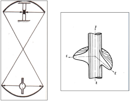
Figure 2.
Principle optical scheme of FZ facility and 3D energy distribution (a.u.) at the focus area, confirmed by temperature measurements via Infra Red optical pyrometer.
It appears more reasonable to use light heating to grow single crystals of oxides and their compounds, especially in those cases when it is difficult to produce perfect single crystals by other methods. For example, this method may be preferred when high oxygen pressure over the melt is necessary, when evaporation and dissociation of the crystallizing material must be preven ted, or for very refractory oxides and related compounds, when a crucible cannot be used. Balbashov and Egorov published an article in 1981 describing the 3rd generation of FZ equipment URN-2-ZM and crystal growth results [15]. The purpose of the current paper is to describe the present generation of the more contemporary and perfect apparatus of this type for crystals growing of refractory oxides and metals (Tm as high as 3000 °C) by floating-zone melting with light heating. The present generation of the apparatus for crystal growth should be considered as the next step in the development of such type of equipment.
The novelties of the apparatus are:
- Change of used mirror geometry,
- New light flux regulation system,
- Use of more precision mechanical systems of moving and rotation of crystals and feed rod,
- General use of micro-processing techniques for all electric and electronic systems with PC control and programming,
- Development and application of PC control and stabilization of grown crystal diameters on the base of the TV-image of the FZ recognition processing.
- Use of single-crystalline high-quality sapphire as material for the high-pressure transparent tube of the crystallization chamber.
A new version of the FZ apparatus has essential advantages over the previous URN-2-ZM:
- -
- More value of light power concentrated in a working focal point as a result of using a lower mirror with bigger scope angle. It leads to increasing of maximal temperature in focus and allows to grow larger size crystals.
- -
- New regulation light flux system without changing the focused power distribution and not disturbing the circular symmetry of the heat field in the focal point.
- -
- Use of micro-processing in all the system increases the long time reliability of the facility.
- -
- The fused quartz was some time ago a unique material for manufacturing of transparent high-pressure tubes of the crystallization chamber. Now the technology of high-quality sapphire crystals is very developed and allows obtaining the tubes of any size. Sapphire have essential advantages against quartz in the durability and strength, and should be estimated as the preferred material for this task.
The experimental results of growing high-quality single crystals of garnets, such as Y3Fe5O12 or Gd3Fe5O12, the ferrites BaF12O19, SrFe12O19 with different substitutions, (NiZn)Fe2O4, orthoferrites, high-quality rutile (TiO2), Rare Earth manganites, Fe-contained langasites, color sapphire, garnet of Al, Ga, and many other oxide compounds using this technique are presented.
2. Apparatus
The growth of oxide crystals by floating zone melting at high temperatures exceeding 2000 °C some time requires satisfaction of the following conditions:
- (a)
- The heating zone should be circular uniform, and the crystallization interface should be near to a flat shape.
- (b)
- The gas-phase over the melt during the crystal growth and annealing should be controlled in order to keep the stoichiometric composition and desired valence of the metal ions.
- (c)
- Annealing of the growing crystals at uniform temperatures sufficient to relieve the tenseness should be provided. Such annealing should be controlled during the crystallization process to allow active influence on crystal growth.
These requirements are satisfied largely with the help of the following FZ melting apparatus using light heating. The principle arrangement is presented in Figure 3.
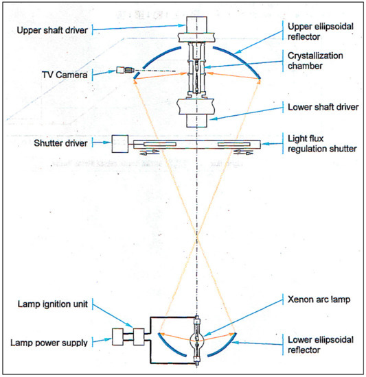
Figure 3.
Optical scheme of FZ URN-5-ZM.
The external view of the facility cupboard is shown in Figure 4A bi-ellipsoidal light concentrator with vertically positioned optical axis is used. Such an arrangement provides circular symmetric heating of the zone and azimuthal uniformity of the temperature over its surface.
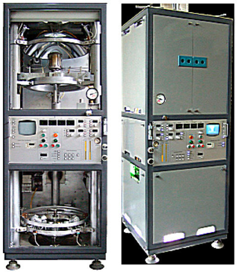
Figure 4.
External view of URN-5-ZM.
The design features of the apparatus are the following:
- -
- Xenon high-pressure short arc lamp as the light energy source; electron stabilization of the light flux;
- -
- Employing special ellipsoidal glass reflectors with a scope angle of 97.5°, 600 mm. diam. (upper mirror) and 250°, 360 mm. dia. (lower mirror) (the specific heat load on the reflector surface does not exceed 0.2 W/cm2),
- -
- Smooth control of the light concentrator aperture (and a light quantity on the subject of heating) ranging from zero to maximum.
- -
- The high-pressure crystallization chamber.
- -
- Low pressure and gas flow crystallization chamber.
Comparison of the two different profiles of azimuth temperature distribution for four mirror heat scheme (4 orthogonal reflectors) and coaxial two reflectors (URN-2-ZP) heat scheme is shown in Figure 5. The coaxial scheme has a clear advantage in azimuth temperature distribution and provides more uniform heating of the melt zone.
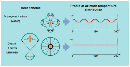
Figure 5.
Profiles of azimuth temperature distribution for four mirrors and coaxial FZ.
The apparatus allows annealing of the growing crystals at temperatures as high as 2500 °C, growth of the crystals in a pure oxygen medium, growth crystals of large diameter by the method of different moving of crystal and small diameter polycrystalline feed rod.
With a light source of 5 or 10 kW electric power, the maximum energy density in the working focus in both cases equals 1500 W/cm2 and 2000 W/cm2, according to radiometric measurements, whereas the average density equals 1000 W/cm2 and 2000 W/cm2, respectively. The use of a lamp with a power of 10 kW gives an effective size of the focal image approximately 50% larger than that of a 5 kW lamp. The highest achievable temperature in the working focus depends on different factors: the optical emissivity of the heated material, the reflectivity of the surface, the heat conductivity and size of the heating object, the pressure in the crystallization chamber, and the temperature in the annealing furnace. The abovementioned energy characteristics in the focus area allow the melting in the air and to be subjected to zone crystallization with refractory oxides such as ZrO2, HfO2, and MgO of diameter about 6–8 mm. The optical scheme of the setup supplied with a xenon lamp placed in the lower mirror focus provides a maximum coefficient of utilization of the light flux of the lamp. The light flux power concentrated on the heating object under normal conditions is approximately 30% of the electric source power. Energetic efficiency could be enhanced by increasing the scope angle of the lower ellipsoidal mirror (Figure 6). The maximal scope angle for lower mirror is about 260° in accordance with a maximal angle of luminous intensity of xenon lamp (Figure 7).
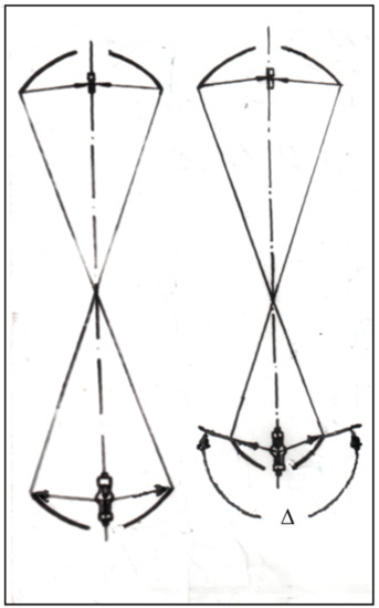
Figure 6.
Different scope angle Δ of lower mirror: left- near 180°, right 220–260°.
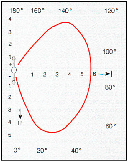
Figure 7.
Typical space angle dependence of short arc xenon lamp luminous intensity (solid red line) (plane section) [16].
One of the serious problems arising in growing single crystals of many oxide compounds is saving the stoichiometric composition during growth. The loss of oxygen or the evaporation of other components could deviate the composition from the stoichiometry. To attain equilibrium partial pressures of the components in the gas phase, it is necessary to provide in some instances a pressure excess over the melt of tens, and at times, hundreds of atmospheres. In our apparatus the crystallization chamber allows keeping a gas pressure in the growth zone up to 100 bar (experimental data). The chamber design is shown in Figure 8).
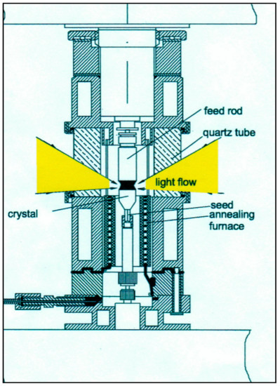
Figure 8.
Crystallization chamber for. high gas pressure.
Figure 9 shows the construction of the crystallization chamber for low (about four atm) gas pressure and gas flow. Ceramics of LaCrO3 could be used as a heating element at a maximum temperature of 1750 °C.
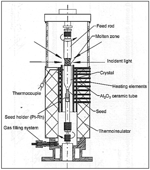
Figure 9.
Crystallization chamber for low gas pressure and gas flow.
The major element of the chamber is a ring-shaped power container made from optical grade fused quartz or from single-crystalline sapphire. The calculated maximal pressure inside the space of the crystallization chamber equals about of 250 bar (very approximate) for wall thickness 25 mm (quartz) or 15 mm (sapphire) and internal diameter 30 mm. The actual maximal pressure determined by the presence of defects (local crystallization in quartz, tenseness, etc.) in the container wall is what decrease its strength. In order to decrease the temperature at the inner surface of the quartz or sapphire container, and to protect it against deposition of the growing compound or its components, it is necessary to incorporate one changeable thin-walled quartz tube into the inner cavity. The sealing of the chamber is made by silicone rubber O-rings. Figure 10 illustrates the quartz and sapphire elements of the crystallization chamber with thin wall tube inside. The sapphire element is more reliable because it has higher strength, although it has a higher temperature extension coefficient than quartz.
Figure 10.
Quartz (left) and single-crystalline sapphire elements (right) for working under high gas pressure.
The annealing of crystals under oxygen pressure during of crystal growth is realized with the aid of a platinum-rhodium alloy wire coil element assembled in two alumina tubes furnace sealed by Thermo resistive cement. The maximum temperature of the annealing furnace is 1650 °C when a Pt + 20% Rh alloy is used as the heater. For annealing, temperatures as high as 2500 °C could be used Mo wire with a protective gas flowing through the crystallization chamber. The electron stabilization of the light flux provides a constant of temperature in the melt zone of ± 2 °C at the level of 1800 °C (according to the radiation pyrometer measurements. In Figure 11, Figure 12, Figure 13 and Figure 14, the arrangements of different systems of FZ URN-5-ZM are shown.
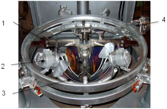
Figure 11.
Arrangement of low mirror, xenon lamp, and lamp. blowing drivers. 1. Xenon lamp, 2. Lamp blower, 3. Lower ellipsoidal mirror, 4. Motor driver for lamp displacement.
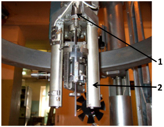
Figure 12.
Arrangement of crystal moving system. 1. Motor of crystal. rotation driver; 2. High precise nut-ball mechanism (inside of cylindrical cover).
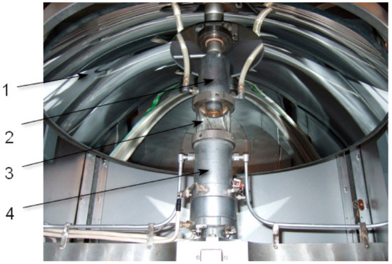
Figure 13.
High-pressure crystallization chamber. 1. Upper ellipsoidal mirror, 2. Upper flange, 3. Sapphire tube of crystallization chamber, 4. Lower flange.
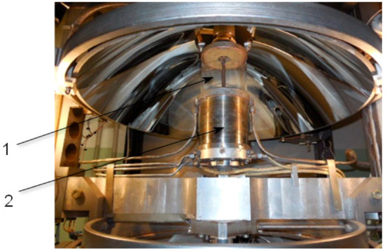
Figure 14.
Gas flow and low pressure (4 atm) crystallization chamber. 1. Large diameter quartz tube, 2. Box with annealing furnace inside.
The crystal rotation set is shown in Figure 15. This set could service the apparatus outside and lightly and conveniently insert in the moving lover shaft driving immediately before the crystal growth process.
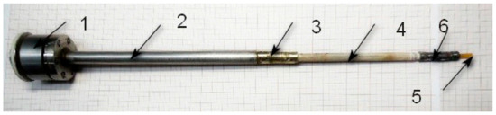
Figure 15.
Crystal rotation set: 1. Magnetic muff rotation driver, 2. Tube for rotation shaft, 3. Rotation axiality tuning device, 4. Alumina rod, 5. Seed, 6. Pt seed holder.
Figure 16 illustrate the PC interface of the program module for the operative control of the FZ process.
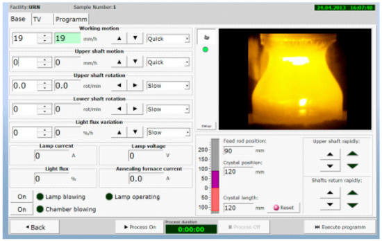
Figure 16.
User PC interface of the program module for the operative control of the FZ process.
The system of control and stabilization of the grown crystal diameter based on floating zone digital image recognition. Image recognition consists of the floating zone profile extraction and the control by the PC of the floating zone shape (Figure 17). The aspects ratio of the FZ profile is compared with etalon FZ aspect ratio from a special library; thus, feedback signal could be calculated and used for stabilization of the crystal diameter. Principles for the design of a software are developed for automation of the floating zone crystal growth. The image video signal processing algorithms of the melt zone are elaborated, allowing to significantly reduce the noise levels of various natures. A method of image processing allows optimization of the building contours of the object, the most suitable for use in the processed automation system. Such a system is useful, especially at large scale production of technically applied crystals, for instance, rutile, strontium titanate, YFe garnet, orthoferrite, ferrospinel, and gallium oxide.
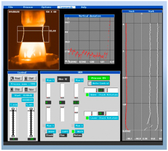
Figure 17.
PC screen panel of the crystal diameter stabilization program via TV FZ image recognition.
On Figure 18 the front panel of FZ equipment is shown for manual control of crystal growth and estimation and control of all parameters of current process.
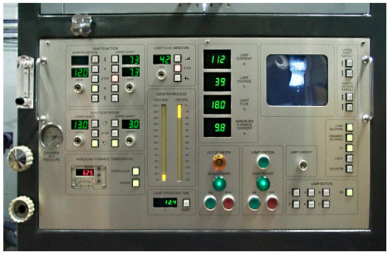
Figure 18.
Manual control panel for FZ URN-5-ZM.
The correct design of the light regulation system is very important. This system should allow the smooth changing of the light value on the floating zone in diapason 0–100%, manually or automatic, and minimum distortion of the circular uniformity of the light flux. For this, the light shutter made from 8, 12, or 16 synchronous moved in the radial direction sectors used, as shown in Figure 19.
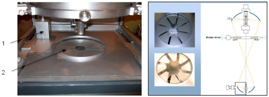
Figure 19.
The light shutter of FZ URN-5-ZM. 1. Shutter driver, 2. Moving sectors.
At the crystal growth of the gas pressure and gas flow, the crystallization chamber should be cleaned carefully with the help of a vacuum system, including the for-vacuum and turbo vacuum pumps.
For the crystal growth, it is necessary to use the xenon lamp of 7–10 kW electric power and annealing furnace of large diameter about 27–30 mm for obtaining maximal crystal diameter of the technically useful oxide materials, such as strontium titanate or rutile. The temperature of the annealing furnace should be maintained at the level of 1350°C–1650°C. Maximal crystal diameter for these materials is about 23–25 mm. In Figure 20, the melting zone shape is shown on top of the annealing furnace.
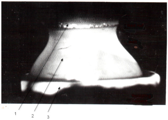
Figure 20.
Melting zone shape at the crystal growth of a big diameter (15–20 mm.). 1. feed rod, 2. melt, 3. top edge of annealing furnace.
Technical parameters of FZ URN-5-ZM
Light source electric power (xenon short arc lamp) → 3–10, 15(water-cooled) kW
Maximum gas pressure in the crystallization chamber → 10 MPa (100 bar)
Vacuum in the crystallization chamber → 10−3 Pa
Average light flux density in the work focus (cylindrical rod 1 cm in diameter, lamp 5 kW) → 500 W/cm2
Maximal object temperature in the open crystallization chamber → 3000 °С
Maximal crystal diameter (oxide material, melting temperature about 1700 °C) → 25 mm
Maximal crystal length → 130 mm
Crystal growth rate → 0–130 mm/h
Maximal annealing furnace temperature → 1600 °С
Temperature stabilization precision of heating objects → ± 0.1%
Power consumption (lamp 5 kW) → 8 kW
Water-cooing rate (with water-cooled xenon lamp) → 1.0 l/min
External dimensions of apparatus (W × D × H) → 850 × 850 × 2500 mm
Weight of apparatus with xenon lamp power supply → 700 kg
3. Growth of Single Crystals
The crystal growth equipment URN-5-ZM destined for growing single crystals of different materials with melting points of up to 3000 °C were mainly of the oxide type but very applicable for crystal growth of tight melting semiconductors and metals as LaB6, LaB12, inter metals, such as Ru2Si3 at.al. [17,18].
3.1. Rotation Effect
Due to the very high axial symmetry and circular uniformity of heating in this FZ optical system geometry, the crystal growth is possible without any axial rotation of crystal. The high structural properties of crystal could be obtained in this regime. For instance, the rutile (TiO2) crystal that was grown with no rotation is shown in Figure 21. The natural non-circular shape of the faceting is indicated for such a crystal. This effect could be clearly observed for incongruently melted compounds, and in some cases, the obtaining of perfect crystals is very problematic, for example, for Y3Fe5O12, Ba(Sr)Fe12O19 pure or with substitutions, Ca2(FeAl)2O5, Sr2Fe2O5, etc.
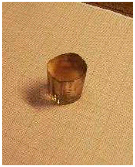
Figure 21.
TiO2 grown with no rotation.
This effect is due to little nonuniformity of the strict circular symmetry of the melting zone under heating. The minor temperature modulation on the periphery of the growth interface at the crystal rotation leads to fast local crystallization near the crystal surface. This parasitic crystallization could transmit in crystal volume and disturb all the processes of crystal growth. For minimization of the crystal rotation effect on the crystal growth, the application of very precisely shaped ellipsoid mirrors is necessary. Especially, it is important for the lower mirror with the xenon lamp for the reason of the large optical way to the upper focused ellipsoid mirror and the small geometrical defects of the lower mirror lead to enhanced distortion of the circular geometry of the heat field in the work of the focal point.
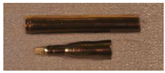
The tuning of the optical system for obtaining almost flat crystal melting interfaces is very important for crystal growth of incongruently melted compositions. For example, such material, such as Sr2Fe2O5, is grown much better without rotation (Figure 22). It means that the interface is not flat on the periphery, and therefore, the optical tuning of the system is not complete. Different degrees of perfection of the interface could be seen in Figure 23 due to the different quality of the tuning of the optical system.
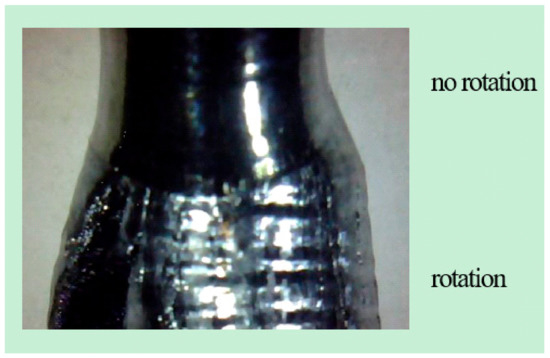
Figure 22.
Crystal Sr2Fe2O5 grown with no rotation on top of the crystal tube and with rotation on the bottom. (Crystal diameter 8 mm.).
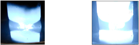
Figure 23.
Influence of the FZ URN-5-ZM optical system tuning on the surface of the melting zone (with no rotation). Left—bad tuning, right—better tuning (diameter of the rode equals to 7 mm.).
3.2. Y3Fe5O12
Yttrium iron garnet and other Rare Earth Iron garnets have an incongruent melting point; therefore, they could be grown from the flux, basically, where different light melting oxides are used as solvents. Iron oxide could be used as the solvent according to the phase diagram of the system Fe2O3–Y2O3 (Figure 24) [19].
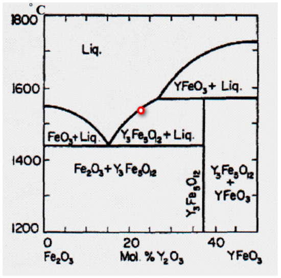
Figure 24.
Phase diagram of the system Y2O3–Fe2O3.
The solution, in this case, must have an approximate composition: 25 mol% Y2O3 and 75 mol% Fe2O3 (the red point in Figure 24). The arrangement of Fe2O3 rich solid solution bar in the feed rod is shown in Figure 25. To obtain perfect Y3Fe5O12 single crystals by FZ, it is advisable to grow them under oxygen pressure in order to decrease the content of FeO in the crystal and increase the distance between the eutectic and peritectic temperatures from 86 °C at normal pressure to 200 °C, at P(O2) = 100 bar. [19]. This will reduce the probability of a second phase arising in the crystal and increase the structural perfection of the crystal.
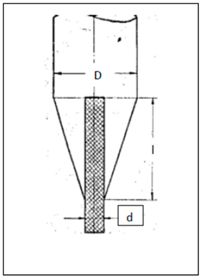
Figure 25.
Ceramic feed rod with inserted of Fe2O3 rich composed bar (D3 = d2 + l/1.5).
The FZ growth process has been studied in the oxygen pressure range of 0.2–70 bar. It was found that perfect crystals with appropriate electromagnetic characteristics could be obtained at 20–30 bar. At the growth rate of 1.5 mm per hour, the ferromagnetic resonance curve width in the 3 cm wavelength band equals about 0.4 Oe (diameter of the sphere equals 4 mm). The diameter of the crystal equals 8 mm, and the length can reach 70 mm. The initial part of the crystal grown on the seed with 3 × 3 mm2 cross-section is illustrated in Figure 26. The equilibrium dissociation pressure is in the range of air oxygen pressure because Y3Fe5O12 crystals that are grown under the pressure of 10 bar exhibit p-type conductivity. P-type conductivity reverses to the n-type during Ar annealing. The electrical resistance of the crystals grown under 20 atm. exceeds 1012 Ohm. cm. The electrical resistance of the crystals grown in air equals to 107–108 Ohm.cm.
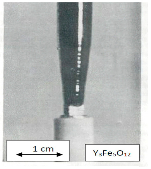
Figure 26.
Initial part of Y3Fe5O12.
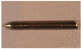
3.3. Gd3Fe5O12
The interval between the eutectic and peritectic temperatures for this incongruently melting compound is about half of that for Y3Fe5O12 [20]; therefore it is necessary to provide higher oxygen pressure to obtain crystals free from second-phase inclusions. Crystals with a diameter of 6 mm and 70 mm long are grown under 50 bar pressure at a growth rate of 1.5 mm/h. The optical absorption coefficient at the wavelength of 1.5 μ is less than 0.5 cm−1.
3.4. BaFe12O19
This compound also melts incongruently in air. Congruence could be achieved under more than 40 bar of oxygen pressure [21]. At this pressure, no formation of bivalent iron oxide phases takes place. The concentration of FeO in the composition as the solid solution could be in an amount about 1–2 w%. When the pressure of O2 is about 100 bar, the contamination of FeO in crystals is about zero. Typically, Barium and Strontium hexaferrite crystals of 8 mm diameter grown under oxygen pressure of 70 bar at the rate of 6 mm/h. The crystallographic c-axis is always oriented normally to the growth direction regardless of the seed orientation. For example, the ferromagnetic resonance curve width of BaFei2O19 single crystals grown under 50 bar pressure equals 40 Oe (sphere diam. 1 mm.). The same parameter for SrFe12O19 single crystals grown under the same conditions equals to 18 Oe. The single crystal compositions of many hexaferrites with different substitutions are shown in Table 2.
3.5. (NixCo1−x) Fe2O4
The crystals of (NixCo1−x) Fe2O4 with x = 0, 0.25, 0.5, 0.75, and 1.0 are grown under oxygen pressures of 10–15 atm. at the growth rate of 6–10 mm/h. The crystal diameter is 10–12 mm. The single crystal boules have the pronounced facets in dependence on the seed orientation. The bulk electric resistance of the crystals is 102–103 Ohm. cm, due to the presence of FeO in the solid solution.
3.6. Ni0.5Zn0.5Fe2O4
Single crystals are grown under the pressure of 40 atm. exhibiting p-type electro-conductivity, which reverses to the n-type during vacuum or Ar annealing. The electrical resistance of the crystals grown under the pressure of 50 bar exceeds 108 ohm cm. The electrical resistance of the crystals equals 102–103 ohm cm when they are grown in air.
Single crystals with a diameter of 8 mm are grown at a rate of 10 mm/h. Evaporation of the zinc oxide reduced substantially during growth under the oxygen pressures above 50 bar.
3.7. Mn0.5Zn0.5Fe2O4
Single crystals with diameter of 20 mm and 50 mm long are grown by FZ melting of the polycrystalline rod with diameter of 12 mm at the rate of 10 mm/h in air. Initially, the polycrystalline has the composition Mn0.3Zn0.7Fe2O4 to compensate for the loss of zinc oxide due to evaporation. Single crystals with an initial magnetic permeability of 5000 Gauss/Oe were obtained.
3.8. RFeO3 (R-Rare Earth Element)
All crystals are grown in air and under oxygen pressure. The optical properties of some of these orthoferrites, for instance YFeO3 and TmFeO3, are almost independent of the gas media around the floating zone, whereas other orthoferrites are very sensitive to this parameter (for instance, the transparency of the GdFeO3 and HoFeO3 orthoferrites in the IR region increases substantially if the growth occurs under oxygen pressure above 5 bar). Good quality of Y, Tm, and Dy orthoferrite crystals with a diameter of 20 mm and 80 mm long could be achieved if they are grown by the FZ melting of a tick rod in air and at the growth rate of 10 mm/h.
3.9. TiO2
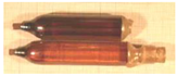
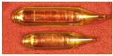
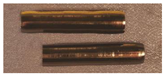
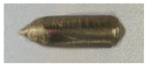
Rutile (TiO2) crystal is one of the most suitable materials for various optical applications, like polarizing devices, spectral prisms, and optical isolators. It has a high refractive index and a large birefringence. Single crystals of rutile that are grown by the FZ URN-5-ZM apparatus as cylindrical boules with diameters equals up to 25 mm and up to 100 mm long have high quality. The TiO2 crystals grown in CO2 gas flow and special annealing temperature programs are shown in Figure 27. The different patterns of FZ rutile crystals and some properties are shown in Figure 28, Figure 29, Figure 30 and Figure 31. The FZ technology allows obtaining single rutile crystals ready for application immediately after crystal growth.
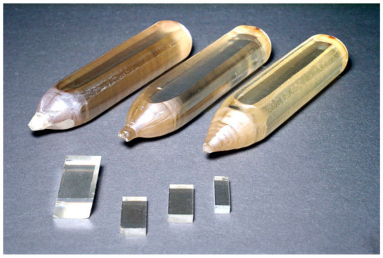
Figure 27.
Single crystals of rutile are about 20 mm in diameter and small fragments of rutile.
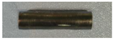
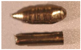
Figure 28.
Rutile single crystal after crystal growth and annealing immediately. The diameter equals to 20 mm.
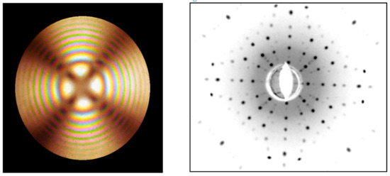
Figure 29.
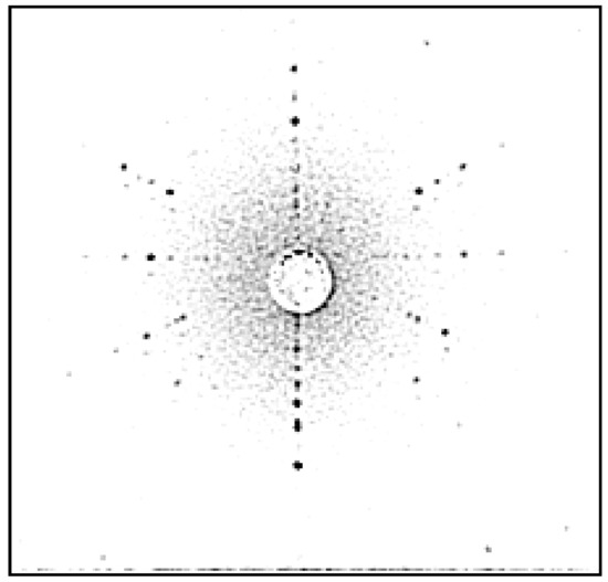
Conoscopic Cross and Laue pattern of TiO2 crystal in the direction [001].
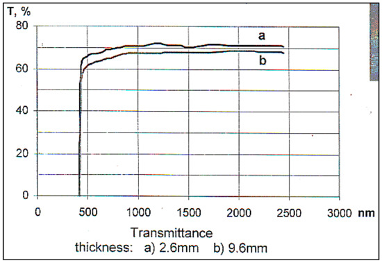
Figure 30.
Optical spectra of the TiO2 crystal. Absorption coefficient: (λ = 1.3 μm), 0.03–0.05 cm−1, (λ = 0.55 μm), 0.08–0.09 cm−1.
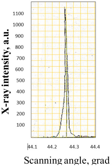
Figure 31.
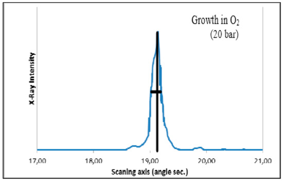
X-ray rocking curve of the TiO2 crystal. Minimal width of the rocking curve is 23 angle sec.
3.10. SrTiO3
Strontium titanate single crystals have a variety of applications as optical material, substrates for thin films deposition, research scientific work, etc. FZ URN-5-ZM is very applicable for obtaining of SrTiO3 single crystals of large diameters and lengths. The floating zone crystal growth technology of this material includes the manufacture of ceramic feed rods with appropriate diameters, lengths, and choice of crystallographic oriented seeds, and their mounting in the FZ apparatus and crystal growth. The annealing furnace of the crystal should be heated to 1500 °C and the distance between the growth interface and the annealing furnace edge must be keep about 1–2 mm. The crystal growth speed is 8–10 mm/h. A more detailed description of the perfect crystal growth is given in [22]. The crystals of SrTiO3 are shown in Figure 32 and some of their properties are given in Figure 33; Figure 34.
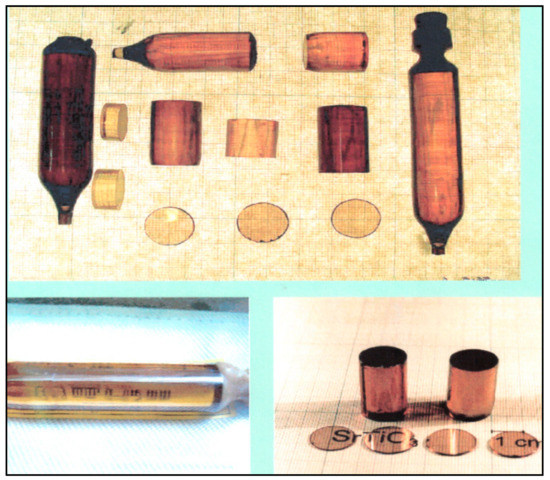
Figure 32.
Single crystals of SrTiO3, grown by FZ in the URN-5-ZM facility.
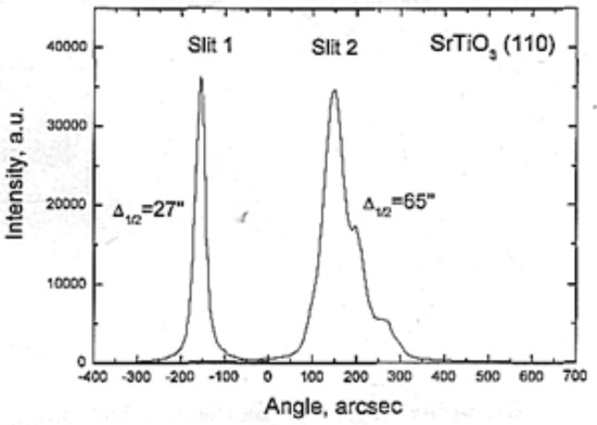
Figure 33.
Rocking curve of FZ SrTiO3 crystal. Left—perfect, right—twinned.
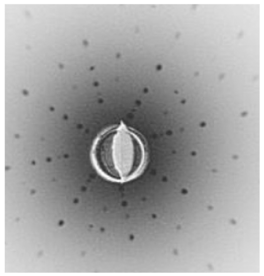
Figure 34.
Laue pattern of SrTiO3 crystal in the direction [001].
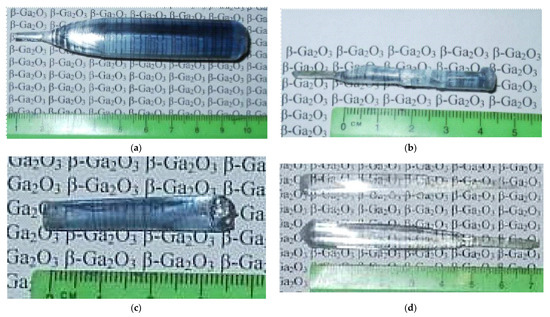
3.11. β-Ga2O3
β-Ga2O3 is very promising wide band semiconductor and the growing of single crystals of this material is an actual challenge. The FZ process of β-Ga2O3 could be applied for obtaining of high-quality crystals. Crystals of β-Ga2O3 could be grown with diameters of 25 mm and 100 mm long. The properties of FZ crystals depends on the partial oxygen pressure around melting zone (Figure 35). During the crystal growth in oxygen gas under pressures over 60 bar, the evaporation and dissociation of β-Ga2O3 are not apparent.
Single crystals of oxide compounds grown by the floating zone technique with optical heating are listed in Table 1, Table 2, Table 3, Table 4, Table 5, Table 6 and Table 7. Single-crystal growth conditions and some other properties are also presented in the tables.

Table 1.
R-Mn-Ca(Sr)-O. (R- La-Lu).
Table 2.
Ba(Sr) Fe (Al, Ti, Sc, Co Zn) –O (Hexaferrites).
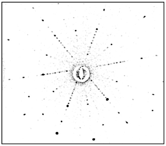
Figure 38.
Laue pattern of BaFe12O19 (orientation near [0001]).
Table 3.
Ni(Co,Fe) -W-O.
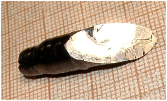
Figure 39.
Crystal of CoWO4 (growth in air, speed 6 mm/h).
Table 4.
Ca(Sr)-Fe(Al,Ga)-O.
Table 5.
Ba(Sr)-Nb(Ta)-Fe-Si-O.
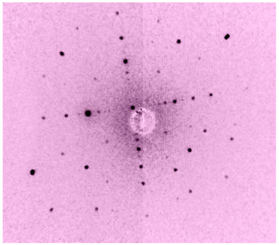
Figure 41.
Laue of Ba3TaFe3Si2O14 (110).
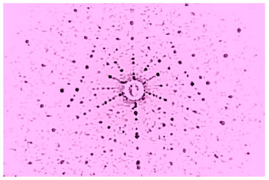
Figure 40.
Laue of Ba3NbFe3Si2O1(111).
Table 6.
Co-Ti-O.
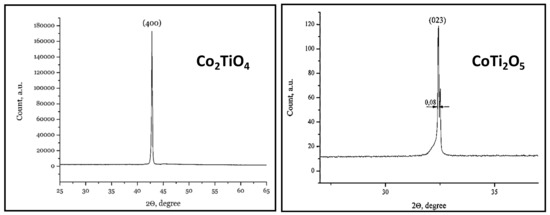
Figure 42.
X-ray diffractometry of single crystals Co2TiO4 and CoTi2O5.
Table 7.
Different single crystals, grown by Floating Zone apparatus URN-5-ZM.
4. Conclusions
URN-2-ZM FZ equipment is a very convenient instrument for crystal growth, zone refining, solid state high-temperature research at very high temperatures of up to 3000 oC. This facility could be used, not only in single-crystalline material research and novel materials search, but also for the scale production of some technically needed crystals, such as rutile, strontium titanate yttrium ferro-garnet, lanthanum borides, gallium oxide, and so on. The property of a facility to work under high pressure of any gas is a very important feature. The evolution of the mechanics, optics, electric and electronic systems, and other technological fields allows us to permanently improve the current design of URN-2-ZM and achieve the best application of innovations for the best-obtained crystal quality.
Acknowledgments
Administrative and technical support of Moscow Power Engineering Institute.
Conflicts of Interest
The author declares no conflict of interest.
References
- Poplawsky, R.P.; Tomas, J.E. Floating zone crystals using an arc image furnace. Rev. Sci. Instrum. 1960, 31, 1303. [Google Scholar] [CrossRef]
- Kooy, G.; Gouwenberg, H.J.M. Zone melting of oxides in a carbon arc image furnace. Philips Techn. Rev. 1962, 23. [Google Scholar]
- Halden, F.F.; Sedlacek, R. Verneuil Crystal Growth in the Arc-Image Furnace. Rev. Sci. Instrum. 1963, 34, 622. [Google Scholar] [CrossRef]
- O’Bryan, H.M., Jr.; O’Connor, P.B. Growth of Nd:YAG crystals by floating zone technique. Am. Ce Soc. Bull. 1966, 45, 578. [Google Scholar]
- Marsch, A.; Fairholme, R.; Gill, G. Domain-wall mobility in orthoferrite crystals grown by float-zone technique. IEEE Transact. Magn. 1971, 7, 470–471. [Google Scholar] [CrossRef]
- Field, W.G.; Wagner, R.W. Thermal imaging for single crystal growth and its application to ruby. J. Cryst. Growth 1968, 3, 799–803. [Google Scholar] [CrossRef]
- Medvedev, S.A.; Balbashov, A.M. Application of arc optical furnace for ferrite crystal growth. In Ferrite; 1968; p. 438, (RussMgian). [Google Scholar]
- Okada, T.; Matsumi, K.; Makino, H. Preparation of othoferrite single crystal by the floating zone technique. Nippon Electr. Compagn. Res. Dev. 1970, 19, 102. [Google Scholar]
- Kitazawa, K.; Nagashima, K.; Mizutani, T.; Fueki, K. A new thermal imaging system utilizing a Xe arc lamp and an ellipsoidal mirror for crystallization of refractory oxides. J. Cryst. Growth 1977, 39, 211–215. [Google Scholar] [CrossRef]
- Kimura, S.; Shindo, I. Single crystal growth of YIG by floating zone method. J. Cryst. Growth 1977, 41, 192. [Google Scholar] [CrossRef]
- Tsuiki, H.; Kitazama, K.; Masumoto, K.; Shiroki, K.; Fueki, F. Single crystal growth of pure and Nd-doped Y2O3 by floating zone method with Xe arc lamp imaging furnace. J. Cryst. Growth 1980, 49, 71–76. [Google Scholar] [CrossRef]
- Takei, H.; Kitamura, K. Growth of FeTiO3 (ilmenite) crystals by the floating -zone method. J. Cryst. Growth 1978, 44, 629. [Google Scholar] [CrossRef]
- Eyer, A.; Nitsche, R.; Zimmerman, H. A double-ellipsoid mirror furnace for zone crystallization experiments in spacelab. J. Cryst. Growth 1979, 47, 219–229. [Google Scholar] [CrossRef]
- Shindo, I. Single crystal growth of akermanite (Ca2MgSi2O7) and gehlenite (Ca2Al2SiO4) by the floating zone method. J. Cryst. Growth 1979, 46, 569. [Google Scholar]
- Balbashov, A.M.; Egorov, S.K. Apparatus for growth of single crystals of oxide compounds by floating zone melting with radiation heating. J. Cryst. Growth 1981, 52, 498. [Google Scholar] [CrossRef]
- Rokhlin, G.N. Technical description of Xenon short arc lamp. In Gas Discharge Light Sources; Énergoatomizdat: Moscow, Russia, 1991; p. 691. (In Russian) [Google Scholar]
- Souptel, D.; Behr, G.; Ivanenko, L.; Vinzelberg, H.; Schumann, J. Floating zone growth and characterization of semiconducting Ru2Si3 single crystals. J. Cryst. Growth 2002, 244, 296–304. [Google Scholar] [CrossRef]
- Sampathkumaran, E.V.; Mohapatra, N.; Iyer, K.K.; Cao, C.D.; Loeser, W.; Behr, G. Magnetic anomalies in single crystalline ErPd2Si2. J. Magn. Magn. Mater. 2008, 320, 1549–1552. [Google Scholar] [CrossRef]
- Van Hook, H.J. Phase relation in the ternary system Fe2O3-FeO-YeFeO3. J. Am. Ceram. Soc. 1962, 45, 162–165. [Google Scholar] [CrossRef]
- Van Hook, H.J. Phase equilibrium studies in the system iron oxide Y2O3-Gd2O3. J. Am. Ceram. Soc. 1962, 45, 369–373. [Google Scholar] [CrossRef]
- Van Hook, H.J. Thermal stability of barium ferrite (BaFe12O19). J. Am. Ceram. Soc. 1964, 47, 579–581. [Google Scholar] [CrossRef]
- Nabokin, P.I.; Souptel, D.; Balbashov, A.M. Floating zone crystal growth and properties of SrTiO3. J. Cryst. Growth 2003, 250, 397–404. [Google Scholar] [CrossRef]
- Vocabulary Landolt-Bornstein.
© 2019 by the author. Licensee MDPI, Basel, Switzerland. This article is an open access article distributed under the terms and conditions of the Creative Commons Attribution (CC BY) license (http://creativecommons.org/licenses/by/4.0/).