Article

Investigation of Piezoelectric Ringing Frequency Response of Beta Barium Borate Crystals

by
Giedrius Sinkevicius
1,2,* and
Algirdas Baskys
2
1
Department of Material Science and Electrical Engineering, Center for Physical Sciences and Technology, Saulėtekio av. 3, LT- 10257 Vilnius, Lithuania
2
Department of Computer Science and Communications Technologies, Vilnius Gediminas Technical University, Naugarduko st. 41, LT- 03227 Vilnius, Lithuania
*
Author to whom correspondence should be addressed.
Crystals 2019, 9(1), 49; https://doi.org/10.3390/cryst9010049
Submission received: 19 December 2018 / Revised: 13 January 2019 / Accepted: 15 January 2019 / Published: 17 January 2019
(This article belongs to the Special Issue Crystal Growth of Multifunctional Borates and Related Materials)

Abstract

:
The piezoelectric ringing phenomenon in Pockels cells based on the beta barium borate crystals was analyzed in this work. The investigation results show that piezoelectric ringing is caused by multiple high voltage pulses with a frequency in the range from 10 kHz up to 1 MHz. Experimental investigation of frequency response and Discrete Fourier transformation was used for analysis. The method of piezoelectric ringing investigation based on the analysis of difference of real and simulated optical signals spectrums was proposed. The investigations were performed for crystals with 3 × 3 × 25 mm, 4 × 4 × 25 mm and 4 × 4 × 20 mm dimensions. It was estimated that piezoelectric ringing in the beta barium borate crystal with dimensions of 3 × 3 mm × 25 mm occurred at the 150, 205, 445, 600 and 750 kHz frequencies of high voltage pulses.

1. Introduction

A wide variety of optical modulators are used in laser applications [1,2,3,4,5,6,7]. However, only modulators based on electro-optic and acousto-optic principles are used for high power laser system applications. The electro-optic modulation principle is based on the Pockels effect, which presents the change of refractive index in non-centrosymmetric crystals under the influence of an external electric field. The change in refractive index induces a polarization change of a beam that travels though the crystal of the Pockels cell. This feature allows us to use the Pockels cell as a voltage controlled half-wave plate [8].
Acousto-optic modulation principle is based on Debye-Sears effect combined with Bragg configuration. The mechanical oscillation of piezoelectric wafer on the side of the crystal creates pressure, which increase the refraction, diffraction and interference inside the crystal [8,9]. This effect allows us to employ the acousto-optic modulator as a beam deflector.
The property of any optical modulator is the ability to let through or shut out the laser beam that travels through the modulator. The measure of this property for the electro-optic modulators is contrast ratio; for the acousto-optic modulators - diffraction efficiency. Electro-optical modulators contrast ratio varies from 1000:1 to 2000:1 [10,11,12] and acousto-optic modulators diffraction efficiency from 30 % to 80 % [4,13,14,15].
An essential parameter of optical modulators is the rise and the fall time of the modulator. The rise and fall time of electro-optical modulators can reach 10 ns [4,12] and it varies from 200 ns down to 56 ns for acousto-optic modulators [14,15]. It should be noted that the rise and fall time of the acousto-optic modulator depends on the sound velocity in the crystal and the waist diameter of the beam [14]. The rise and fall time of an electro-optical modulators based on the Pockels cell is defined by the rise and fall time of the high voltage pulse that is applied to the modulator. The required amplitude of the pulse for operation of any type of Pockels cell depends on the material, dimensions of the crystal and wavelength of the laser beam that travels through the Pockels cell crystal [16,17].
There are two types of Pockels cells: transverse and longitudinal [8]. For longitudinal Pockels cells, half-wave voltage (amplitude of pulse, at which the laser beam polarization has been rotated by 90°) may vary from 4kV to 10 kV [18]. For transverse Pockels cells, half-wave voltage varies between 1 kV and 8 kV [19,20]. Pockels cell rise/fall time depends on two factors: capacitance of the crystal and applied voltage rise/fall time. In order to achieve a shorter duration of rise/fall time of the Pockels cell, it is necessary to decrease the values of these parameters. The capacitance is determined by the dimensions and material of the crystal; therefore, the main way for the reduction of the rise/fall time of Pockels cell is improvement of the electronics of the high voltage driver. There are only a few usable concepts for high voltage driver design: metal-oxide-semiconductor field-effect transistors (MOSFET) or bipolar avalanche transistors connected in series [21]. The high voltage drivers based on the MOSFETs connected in series provide the laser beam modulation frequency up to 1 MHz with the 30 ns rise/fall time of pulse and adjustable pulse width [22,23,24,25,26,27]. The bipolar avalanche high voltage drivers allow us to achieve rise time from 7 ns down to 240 ps [28,29,30,31,32,33,34,35]. However, the fall time of the pulse generated by the bipolar avalanche high voltage drivers may be 10 times longer than the rise time of the pulse. Another drawback is that practically, it is not possible to adjust the pulse width. The highest width of high voltage pulse is around 7 ns [35] and the highest achieved frequency is 200 kHz [28].
Pockels cells are characterized by higher contrast ratio and shorter duration of rise/fall time in comparison with the acousto-optic modulators. However, the high voltage pulses with the short rise/fall duration can cause piezoelectrical ringing that induces acoustic waves in Pockels cell crystal. If acoustic waves are not suppressed, they are reflected back inside of the Pockels cell crystal. This phenomenon introduces the elasto-optic effect, which can cause the reduction of Pockels cells contrast ratio [11,36,37,38,39]. This effect has to be investigated in order to find the ways how to reduce the impact of the piezoelectric ringing on the contrast ratio. The beta barium borate (BBO) crystals are usually used for the implementation of Pockels cells. There are many works dedicated to the analysis of effects in BBO crystals, e.g., [11,40,41,42,43]. However, the piezoelectric ringing phenomenon in Pockels cells with BBO crystals was mentioned in merely one research [11] and there are none dedicated to the analysis of high voltage pulse frequency impact on piezoelectric ringing phenomenon.
The investigation results of piezoelectric ringing of the Pockels cells with BBO crystals that operate in high voltage pulse frequency range from 10 kHz up to 1 MHz are presented. The method of the piezoelectric ringing investigation based on the spectrum analysis of difference of real and simulated optical signals is proposed. The investigations are performed for the crystals with 3 × 3 × 25 mm, 4 × 4 × 25 mm and 4 × 4 × 20 mm dimensions.

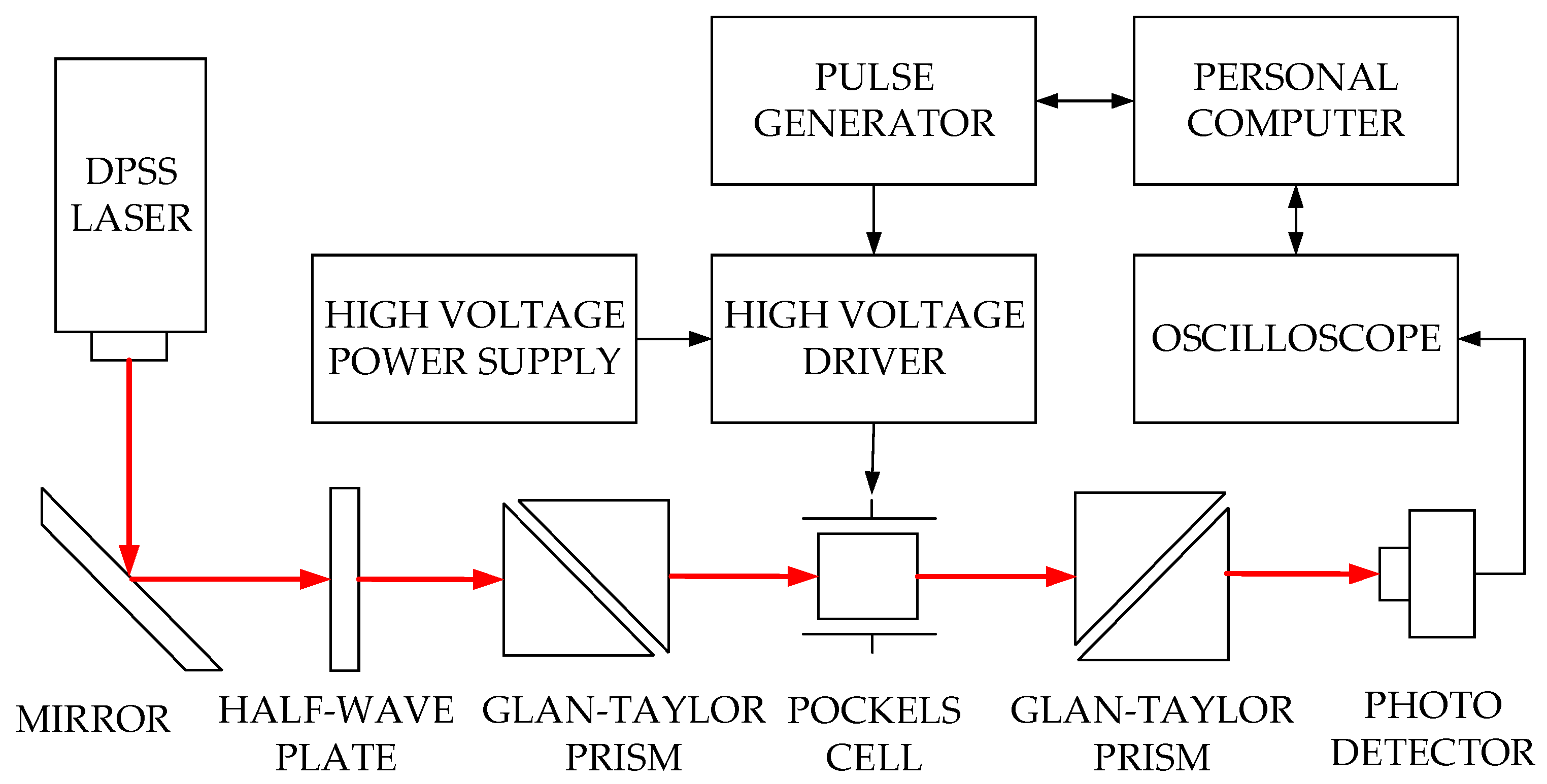
2. Investigation Procedure

Pockels cells based on the BBO crystals were investigated experimentally. A block diagram of simplified single pass contrast ratio measurement setup is given in Figure 1. A 1064 nm wavelength diode-pumper solid state (DPSS) laser with 1.5 mm beam diameter and 2 W power was used in this setup. Half-wave plate with antireflective (AR) coating at 1064 nm was used to alter beam polarization of the DPSS laser. Glan-Taylor polarizing prism was selected for its high extinction ratio, which is higher than 100,000:1 [44]. This prism is used in order to let through only the p-polarized beam. The optical attenuator in combination with half-wave plate was employed in order to adjust the power and to avoid the saturation of photodetector. Laser beam from the first Glan-Taylor polarizing prism travels through the Pockels cell and after that to the second Glan-Taylor prism. The light intensity was detected via a high-speed Si photodetector (DET10A/M, Thorlabs, Newton, NJ, United States, 2013). It must be noted that the phases of the first and the second Glan-Taylor polarizing prisms were mutually turned by 90°, i.e., the second Glan-Taylor polarizing prism was used as an analyzer.
Bipolar high voltage power supply (PS2-60-1.4, Eksma Optics, Vilnius, Lithuania, 2015) was used. It provided positive and negative output voltage 1 kV to 1.4 kV. A potential difference of 2.8 kV was possible with this device. Voltage was supplied to the bipolar high voltage driver (DPD-1000-2.9-Al, Eksma Optics, Vilnius, Lithuania, 2015), which produced high voltage pulses and operated on the MOSFET connected in series principle. Pulse width adjustment from 100 ns up to 5 μs was achieved with this driver model. High voltage pulse rise/fall edge duration from 8 ns down to 4 ns was achievable at pulse frequencies up to 1 MHz. Frequency and duration of the high voltage pulses was assigned via pulse generator (9530, Quantum composers, Bozeman, MT, United States, 2014).
High voltage pulses from bipolar high voltage driver were supplied to the Pockels cell. When the voltage was applied to the Pockels cell, the output signal of the photodetector became high. When no voltage was applied to the Pockels cell, photodetector output signal was low. Oscilloscope sampled the voltage on the output of the photodetector and captured the oscillograms. The intensity of the laser beam that was recorded by the photodetector can be calculated by [45]:
I = I 0 sin 2 Γ 2   ,
where I0 is the intensity of incident light and Γ is phase retardation, which is calculated using equation:
Γ = 2 π L n 0 2 r i j V λ d   ,
where L is the crystal length, n0 is the refractive index, rij is the electro-optic coefficient, V is the voltage applied, λ is the wavelength of the laser beam and d is the crystal thickness.
Contrast ratio was calculated using the intensity value of optical signal, which was captured by the oscilograms, applying equation [46]:
1 C R = 1 ( I max I min )   ,
where:
I max = 1 t 0 t p w t 0 t p w U d ( t ) d t   ,
I min = 1 t p t p w t p w t p U d ( t ) d t   ,
where Ud(t) is the voltage of photodetector, t0 is moment at which the optical pulse starts, tpw is the width of optical pulse and tp is the period of the pulses. Imax and Imin are the average of maximum and minimum intensity of the optical signal in the input of the photodetector.
The contrast ratio of Pockels cells was measured in the high voltage pulse frequency range 10 kHz up to 1 MHz. Oscilloscope data were sampled and the frequency was changed with the step of 3 kHz automatically via software developed by the authors.
Measurements were performed for the the BBO Pockels cell crystals with the following dimensions:
  • 3 mm × 3 mm × 25 mm
  • 4 mm × 4 mm × 25 mm
  • 4 mm × 4 mm × 20 mm

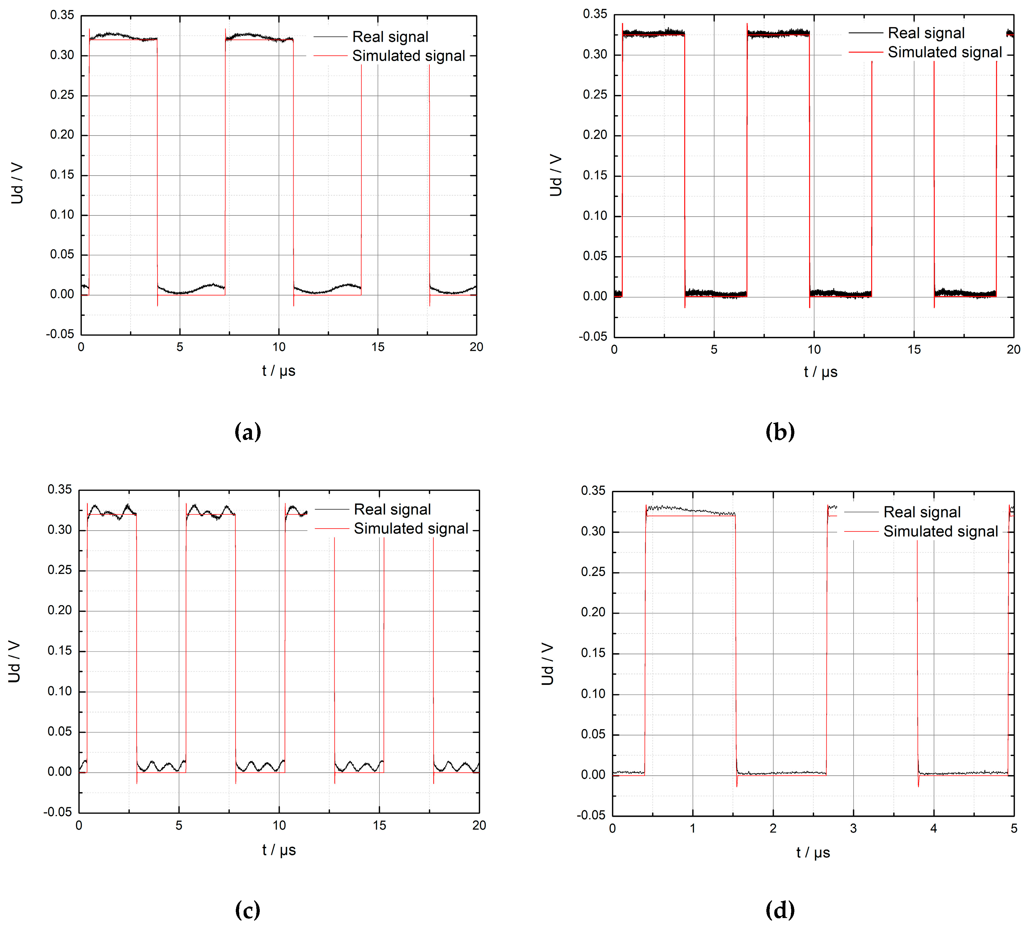
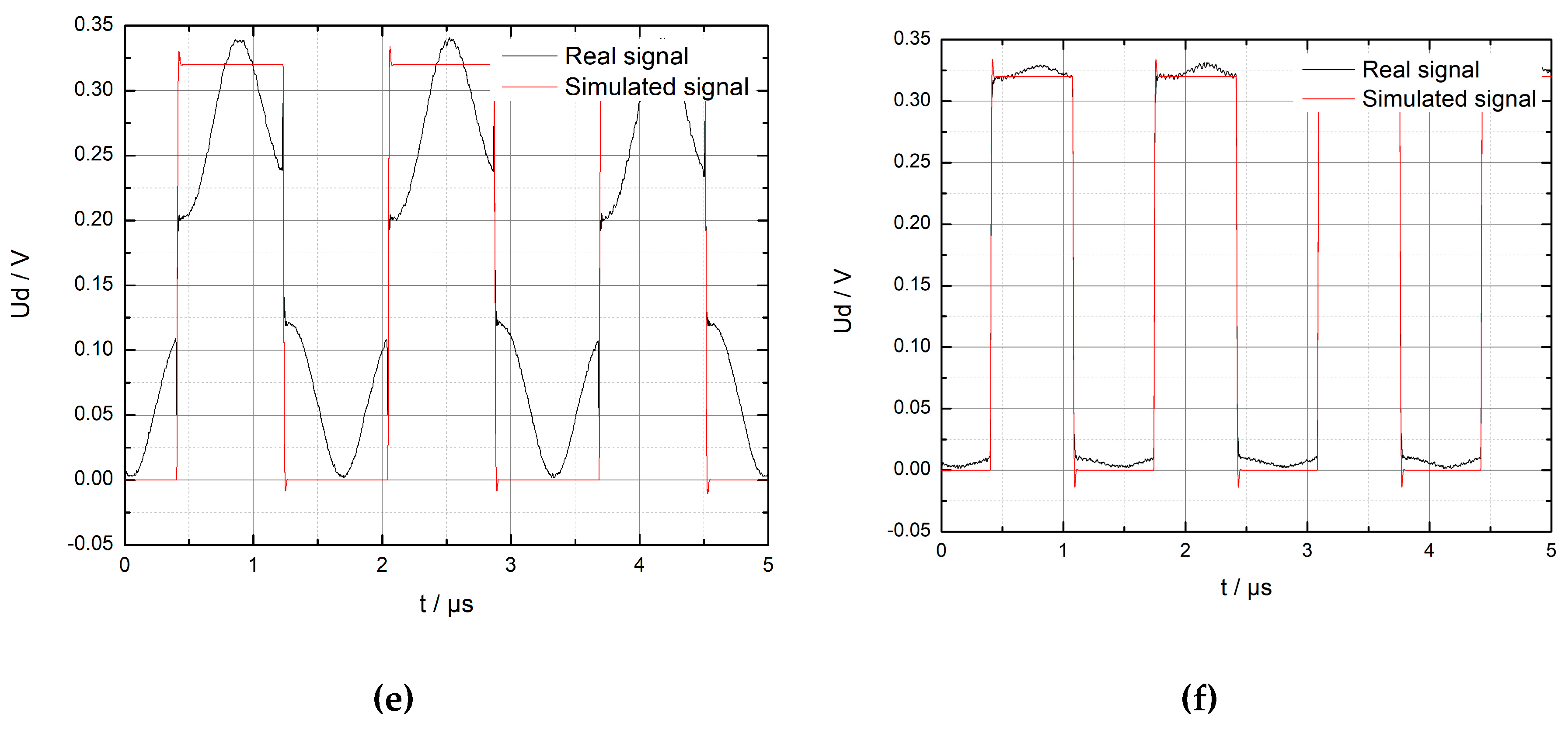
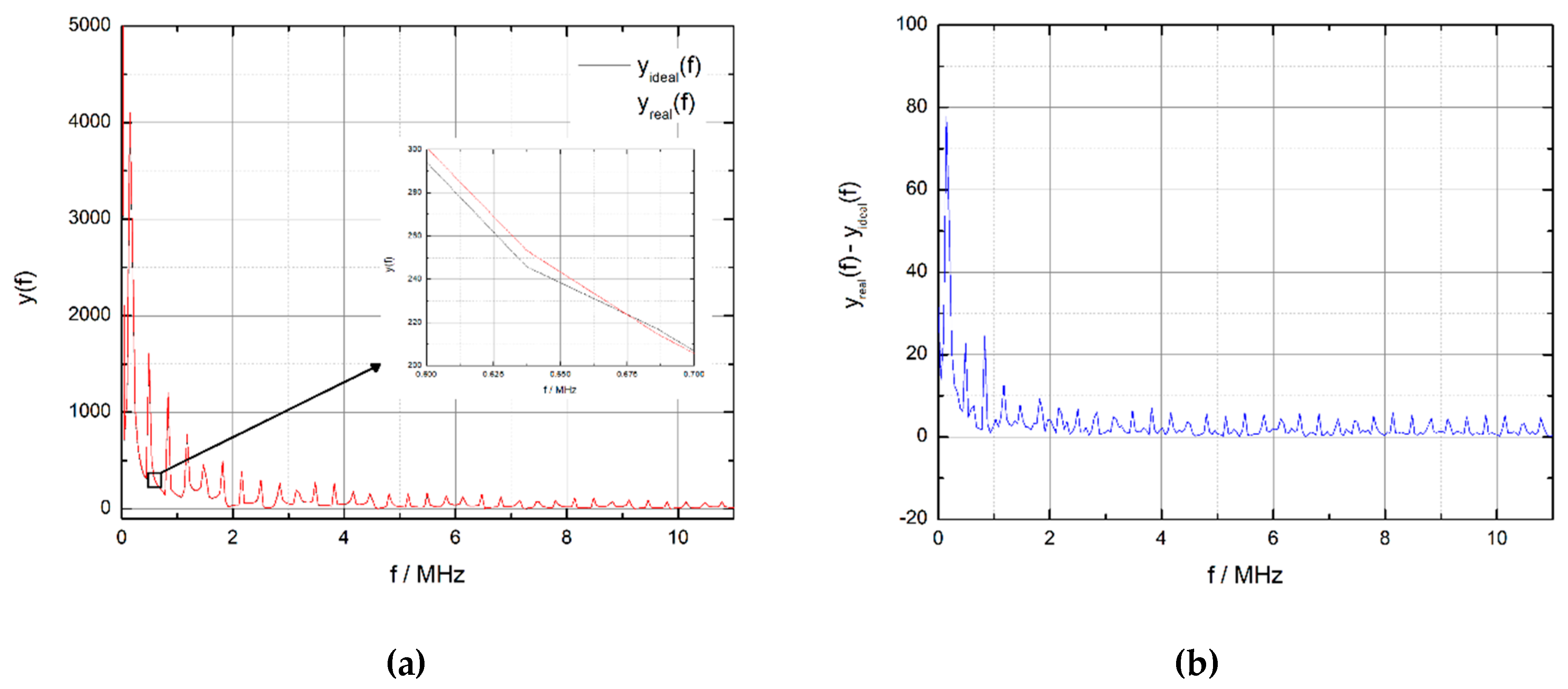
3. Investigation Results

Photodetector signal oscilograms for Pockels cells with BBO crystals of 3 × 3 × 25 mm, 4 × 4 × 25 mm and 4 × 4 × 20 mm dimensions were captured at high voltage pulses in ranges from 10 kHz to 1 MHz with 3 kHz steps. Photodetector signal for Pockels cell with 3 mm × 3 mm × 25 mm BBO crystal is presented in Figure 2. Additionally, the simulated square wave signal of photodetector is presented in Figure 2. The simulation was performed using LabVIEW software (National Instruments, Austin, TX, United States, 2016) the model used for simulation did not take into account the piezoelectric ringing phenomenon of the Pockels cell crystal.
The photodetector signal was close to the simulated square wave signal, just at the 180 kHz high voltage pulse frequency (Figure 2b). This showed that the piezoelectric ringing did not occur at the 180 kHz frequency. However, in all other oscillograms that are presented in Figure 2, optical signal was distorted as compared to the simulated square wave signal. Distortion of the photodetector signal was the consequence of the piezoelectric ringing phenomenon. Oscilograms presented in Figure 2a,c–f show that the period of oscillations caused by the piezoelectric ringing phenomenon depended on the high voltage pulse frequency. The highest distortion of the optical signal was recorded at the 600 kHz high voltage pulse frequency (Figure 2e). This happens because the frequency of the piezoelectric ringing coincided with the frequency of high voltage pulses in this situation and, therefore, some resonance occurred.
The signals caused by the piezoelectric ringing oscillations at 150 kHz, 205 kHz, 445 kHz, 600 kHz and 750 kHz frequencies were analyzed using discrete Fourier transform (DFT):
y ( f ) = n = 0 N 1 x n e j 2 π k n / N
where n = 0, 1, 2, …, N−1, x is input sequence, N is the number of elements of x and y is the transform result.
Spectrums of real and simulated photodetector signals at the 180 kHz high voltage pulse frequency obtained using DFT are presented in Figure 3a. The difference of real and simulated photodetector signal spectrums was calculated to evaluate the spectrum inequality. The result of calculation is presented in Figure 3b. This showed that spectrums of real and simulated signals were close to each other. This fact proves that no piezoelectric ringing oscillations occurred at frequencies up to 11 MHz if the high voltage pulses with 180 kHz were used for the Pockels cell control.
The differences of real and simulated photodetector signal spectrums calculated for the signals obtained at the 150 kHz, 180 kHz, 205 kHz, 445 kHz and 750 kHz high voltage pulse frequencies are presented in Figure 4. The results for 600 kHz frequency are not displayed, since the subtraction result was very high, and therefore, the imaging of the graph would be worsened.
The highest amplitudes of spectrum components obtained for 150 kHz high voltage pulse frequency were observed at 150 kHz and 450 kHz; for 205 kHz at 205 kHz with a lot of lower amplitude components, for 445 kHz at 445 kHz and 890 kHz, and for 750 kHz at 750 kHz.
The piezoelectric ringing in the Pockels cell with BBO with dimensions of 3 × 3 × 25 mm occurred if the spectrum components of the high voltage pulses were near the resonant frequencies of 445kHz, 600 kHz or 750 kHz. Therefore, the acoustic wave suppressors designed for these frequencies had to be applied.
The dependences of Pockels cell BBO crystals contrast ratio on applied high-voltage pulse frequency was obtained by processing the captured oscilograms data using the contrast ratio Equation (3). The obtained dependences of 3 × 3 × 25 and 4 × 4 × 25 mm Pockels cell BBO crystals contrast on applied high-voltage pulse frequency are presented in Figure 5.
The obtained results for Pockels cell with 3 × 3 × 25 mm BBO crystal show that piezoelectric ringing occurred and, because of this, the contrast ratio decreased at 150 kHz, 205 kHz, 445 kHz, 600 kHz and 750 kHz high voltage pulse frequencies. Spectrum analysis shows that piezoelectric ringing at the 150 kHz and 205 kHz frequencies was caused by the third harmonic of high voltage pulses. It is seen (Figure 5) that resonant frequencies depended on the size of the BBO crystal aperture. The resonances of smaller crystal occurred at higher frequencies. When aperture of crystal changes from 3 to 4 mm, the lowest resonance frequency decreased by 36 kHz at the 114 kHz frequency, while for the highest resonance frequency it decreased by 195 kHz at the 550 kHz frequency.
It is seen that with the decreasing of BBO Pockels cell crystal length from 25 mm to 20 mm, the resonance frequency shifted slightly (Figure 6).

4. Discussion

The novel method of piezoelectric ringing analysis of Pockels cells with BBO crystals, which is based on the subtraction of real and simulated photodetector signals spectrums, allows us to observe spectrum components caused by the piezoelectric ringing phenomenon.
The obtained results for Pockels cell with 3 × 3 × 25 mm BBO crystal show that piezoelectric ringing occurred and, because of this, the contrast ratio decreased at 150 kHz, 205 kHz, 445 kHz, 600 kHz and 750 kHz high voltage pulse frequencies. Spectrum analysis shows that piezoelectric ringing at the 150 kHz and 205 kHz frequencies was caused by the third harmonic of high voltage pulses. The frequencies at which the piezoelectric ringing occurred depend on the size of the BBO crystal aperture. The piezoelectric ringing of smaller crystal occurred at higher frequencies. When aperture of crystal changed from 3 to 4 mm, the lowest frequency decreased by 36 kHz at 114 kHz frequency, while for the highest resonance frequency it decreased by 195 kHz at the 550 kHz frequency.
The highest distortion of the optical signal was recorded at the 600 kHz high voltage pulse frequency. This happened because the frequency of the piezoelectric ringing coincided with the frequency of high voltage pulses in this situation, and therefore, some resonance occurred.
The method for piezoelectric ringing suppression in Pockels cells with BBO crystals has to be developed to decrease the impact of this phenomenon on the contrast ratio of Pockels cell.

Author Contributions

G.S. and A.B. wrote the paper and analyzed the data. G.S. performed the experiments.

Funding

This research received no external funding.

Conflicts of Interest

The authors declare no conflict of interest.

References

  1. Yu, T.; Gao, F.; Zhang, X.; Xiong, B.; Yuan, X. Bidirectional ring amplifier with twin pulses for high-power lasers. Opt. Express 2018, 26, 15300–15307. [Google Scholar] [CrossRef]
  2. Rezvani, S.A.; Suzuki, M.; Malevich, P.; Livache, C.; de Montgolfier, J.V.; Nomura, Y.; Tsurumachi, N.; Baltuška, A.; Fuji, T. Millijoule femtosecond pulses at 1937 nm from a diode-pumped ring cavity Tm:YAP regenerative amplifier. Opt. Express 2018, 26, 29460–29470. [Google Scholar] [CrossRef]
  3. Fattahi, H.; Alismail, A.; Wang, H.; Brons, J.; Pronin, O.; Buberl, T.; Vámos, L.; Arisholm, G.; Azzeer, A.M.; Krausz, F. High-power, 1-ps, all-Yb:YAG thin-disk regenerative amplifier. Opt. Lett. 2016, 41, 1126–1129. [Google Scholar] [CrossRef]
  4. Giesberts, M.; Fitzau, O.; Hoffmann, H.-D.; Lange, R.; Bachert, C.; Krause, V. Directly q-switched high power resonator based on XLMA-fibers. In Proceedings of the Fiber Lasers XV: Technology and Systems; International Society for Optics and Photonics, San Francisco, CA, USA, 26 February 2018; Volume 10512, p. 1051218. [Google Scholar] [CrossRef]
  5. Römer, G.R.B.E.; Bechtold, P. Electro-optic and Acousto-optic Laser Beam Scanners. Phys. Procedia 2014, 56, 29–39. [Google Scholar] [CrossRef] [Green Version]
  6. Sun, Z.; Martinez, A.; Wang, F. Optical modulators with 2D layered materials. Nat. Photonics 2016, 10, 227–238. [Google Scholar] [CrossRef] [Green Version]
  7. Munk, A.; Jungbluth, B.; Strotkamp, M.; Hoffmann, H.-D.; Poprawe, R.; Höffner, J. Diode-pumped Alexandrite ring laser for lidar applications. In Proceedings of the Solid State Lasers XXV: Technology and Devices; International Society for Optics and Photonics, San Francisco, CA, USA, 16 March 2016; Volume 9726, p. 97260I. [Google Scholar] [CrossRef]
  8. Eichler, H.J.; Eichler, J.; Lux, O. Modulation and Deflection. In Lasers: Basics, Advances and Applications; Eichler, H.J., Eichler, J., Lux, O., Eds.; Springer Series in Optical Sciences; Springer International Publishing: Cham, Switzerland, 2018; pp. 299–311. ISBN 978-3-319-99895-4. [Google Scholar] [CrossRef]
  9. Rashed, A.N.Z. Best candidate materials for fast speed response and high transmission performance efficiency of acousto optic modulators. Opt. Quantum Electron. 2014, 46, 731–750. [Google Scholar] [CrossRef]
  10. Zhang, F.; Tang, P.; Wu, M.; Huang, B.; Liu, J.; Qi, X.; Zhao, C. Voltage-on-Type RTP Pockels Cell for Q-switch of an Er:YAG Laser at 1,617 nm. J. Russ. Laser Res. 2017, 38, 339–343. [Google Scholar] [CrossRef]
  11. Bergmann, F.; Siebold, M.; Loeser, M.; Röser, F.; Albach, D.; Schramm, U. MHz Repetion Rate Yb:YAG and Yb:CaF2 Regenerative Picosecond Laser Amplifiers with a BBO Pockels Cell. Appl. Sci. 2015, 5, 761–769. [Google Scholar] [CrossRef] [Green Version]
  12. De Groote, R.P.; Budinčević, I.; Billowes, J.; Bissell, M.L.; Cocolios, T.E.; Farooq-Smith, G.J.; Fedosseev, V.N.; Flanagan, K.T.; Franchoo, S.; Garcia Ruiz, R.F.; et al. Use of a Continuous Wave Laser and Pockels Cell for Sensitive High-Resolution Collinear Resonance Ionization Spectroscopy. Phys. Rev. Lett. 2015, 115, 132501. [Google Scholar] [CrossRef]
  13. Donley, E.A.; Heavner, T.P.; Levi, F.; Tataw, M.O.; Jefferts, S.R. Double-pass acousto-optic modulator system. Rev. Sci. Instrum. 2005, 76, 063112. [Google Scholar] [CrossRef]
  14. Wu, Q.; Gao, Z.; Tian, X.; Su, X.; Li, G.; Sun, Y.; Xia, S.; He, J.; Tao, X. Biaxial crystal β-BaTeMo2O9: Theoretical analysis and the feasibility as high-efficiency acousto-optic Q-switch. Opt. Express 2017, 25, 24893–24900. [Google Scholar] [CrossRef]
  15. El-Sherif, A.F.; Harfosh, A. Comparison of high-power diode pumped actively Q-switched double-clad flower shape co-doped-Er3+:Yb3+fiber laser using acousto-optic and mechanical (optical) modulators. J. Mod. Opt. 2015, 62, 1229–1240. [Google Scholar] [CrossRef]
  16. Andreev, N.F.; Babin, A.A.; Davydov, V.S.; Matveev, A.Z.; Garanin, S.G.; Dolgopolov, Y.V.; Kulikov, S.M.; Sukharev, S.A.; Tyutin, S.V. Wide-aperture plasma-electrode pockels cell. Plasma Phys. Rep. 2011, 37, 1219–1224. [Google Scholar] [CrossRef]
  17. Zhang, C.; Feng, X.; Liang, S.; Zhang, C.; Li, C. Quasi-reciprocal reflective optical voltage sensor based on Pockels effect with digital closed-loop detection technique. Opt. Commun. 2010, 283, 3878–3883. [Google Scholar] [CrossRef]
  18. Dorrer, C. Analysis of nonlinear optical propagation in a longitudinal deuterated potassium dihydrogen phosphate Pockels cell. JOSA B 2014, 31, 1891–1900. [Google Scholar] [CrossRef]
  19. Li, C. Electrooptic Switcher Based on Dual Transverse Pockels Effect and Lithium Niobate Crystal. IEEE Photonics Technol. Lett. 2017, 29, 2159–2162. [Google Scholar] [CrossRef]
  20. Ionin, A.A.; Kinyaevskiy, I.O.; Klimachev, Y.M.; Kotkov, A.A.; Kozlov, A.Y.; Kryuchkov, D.S. Selection of CO laser single nanosecond pulse by electro-optic CdTe shutter. Infrared Phys. Technol. 2017, 85, 347–351. [Google Scholar] [CrossRef]
  21. Jiang, W.; Yatsui, K.; Takayama, K.; Akemoto, M.; Nakamura, E.; Shimizu, N.; Tokuchi, A.; Rukin, S.; Tarasenko, V.; Panchenko, A. Compact solid-State switched pulsed power and its applications. Proc. IEEE 2004, 92, 1180–1196. [Google Scholar] [CrossRef]
  22. Rutten, T.P.; Wild, N.; Veitch, P.J. Fast rise time, long pulse width, kilohertz repetition rate Q-switch driver. Rev. Sci. Instrum. 2007, 78, 073108. [Google Scholar] [CrossRef] [Green Version]
  23. Xu, Y.; Chen, W.; Liang, H.; Li, Y.-H.; Liang, F.-T.; Shen, Q.; Liao, S.-K.; Peng, C.-Z. Megahertz high voltage pulse generator suitable for capacitive load. AIP Adv. 2017, 7, 115210. [Google Scholar] [CrossRef] [Green Version]
  24. Baker, R.J.; Johnson, B.P. Series operation of power MOSFETs for high-speed, high-voltage switching applications. Rev. Sci. Instrum. 1993, 64, 1655–1656. [Google Scholar] [CrossRef]
  25. Jiang, W. Fast High Voltage Switching Using Stacked MOSFETs. IEEE Trans. Dielectr. Electr. Insul. 2007, 14, 947–950. [Google Scholar] [CrossRef]
  26. Sundararajan, R.; Shao, J.; Soundarajan, E.; Gonzales, J.; Chaney, A. Performance of solid-state high-voltage pulsers for biological applications-a preliminary study. IEEE Trans. Plasma Sci. 2004, 32, 2017–2025. [Google Scholar] [CrossRef]
  27. Keith, W.D.; Pringle, D.; Rice, P.; Birke, P.V. Distributed magnetic coupling synchronizes a stacked 25-kV MOSFET switch. IEEE Trans. Power Electron. 2000, 15, 58–61. [Google Scholar] [CrossRef]
  28. Krishnaswamy, P.; Kuthi, A.; Vernier, P.T.; Gundersen, M.A. Compact Subnanosecond Pulse Generator Using Avalanche Transistors for Cell Electroperturbation Studies. IEEE Trans. Dielectr. Electr. Insul. 2007, 14, 873–877. [Google Scholar] [CrossRef]
  29. Xuelin, Y.; Hongde, Z.; Yang, B.; Zhenjie, D.; Qingsong, H.; Bo, Z.; Long, H. 4kV/30kHz short pulse generator based on time-domain power combining. In Proceedings of the 2010 IEEE International Conference on Ultra-Wideband, Nanjing, China, 20–23 September 2010; Volume 2, pp. 1–4. [Google Scholar] [CrossRef]
  30. Oak, S.M.; Bindra, K.S.; Narayan, B.S.; Khardekar, R.K. A fast cavity dumper for a picosecond glass laser. Rev. Sci. Instrum. 1991, 62, 308–312. [Google Scholar] [CrossRef]
  31. Tamuri, A.; Bidin, N.; Mad Daud, Y. Nanoseconds Switching for High Voltage Circuit using Avalanche Transistors. Appl. Phys. Res. 2009, 1. [Google Scholar] [CrossRef]
  32. Rai, V.N.; Shukla, M.; Khardekar, R.K. A transistorized Marx bank circuit providing sub-nanosecond high-voltage pulses. Meas. Sci. Technol. 1994, 5, 447. [Google Scholar] [CrossRef]
  33. Dharmadhikari, A.K.; Dharmadhikari, J.A.; Adhi, K.P.; Mehendale, N.Y.; Aiyer, R.C. Low cost fast switch using a stack of bipolar transistors as a pockel cell driver. Rev. Sci. Instrum. 1996, 67, 4399–4400. [Google Scholar] [CrossRef]
  34. Ding, W.; Wang, Y.; Fan, C.; Gou, Y.; Xu, Z.; Yang, L. A Subnanosecond Jitter Trigger Generator Utilizing Trigatron Switch and Avalanche Transistor Circuit. IEEE Trans. Plasma Sci. 2015, 43, 1054–1062. [Google Scholar] [CrossRef]
  35. Bishop, A.I.; Barker, P.F. Subnanosecond Pockels cell switching using avalanche transistors. Rev. Sci. Instrum. 2006, 77, 044701. [Google Scholar] [CrossRef]
  36. Kemp, J.C. Piezo-Optical Birefringence Modulators: New Use for a Long-Known Effect. JOSA 1969, 59, 950–954. [Google Scholar] [CrossRef]
  37. Sinkevicius, G.; Baskys, A. Investigation of frequency response of pockels cells based on beta barium borate crystals. In Proceedings of the 2017 Open Conference of Electrical, Electronic and Information Sciences (eStream), Vilnius, Lithuania, 22–27 April 2017; pp. 1–4. [Google Scholar] [CrossRef]
  38. Yin, X.; Jiang, M.; Sun, Z.; Hui, Y.; Lei, H.; Li, Q. Intrinsic reduction the depolarization loss in electro-optical Q-switched laser using a rectangular KD*P crystal. Opt. Commun. 2017, 398, 107–111. [Google Scholar] [CrossRef]
  39. Wu, W.; Li, X.; Yan, R.; Zhou, Y.; Ma, Y.; Fan, R.; Dong, Z.; Chen, D. 100 kHz, 3.1 ns, 1.89 J cavity-dumped burst-mode Nd:YAG MOPA laser. Opt. Express 2017, 25, 26875–26884. [Google Scholar] [CrossRef]
  40. Adamiv, V.T.; Ebothe, J.; Piasecki, M.; Burak, Y.V.; Teslyuk, I.M.; Plucinski, K.J.; Reshak, A.H.; Kityk, I.V. “Triggering” effect of second harmonic generation in centrosymmetric α-BaB2O4 crystals. Opt. Mater. 2009, 31, 685–687. [Google Scholar] [CrossRef]
  41. Andrushchak, A.S.; Adamiv, V.T.; Krupych, O.M.; Martynyuk-Lototska, I.Y.; Burak, Y.V.; Vlokh, R.O. Anisotropy of piezo- and elastooptical effect in β-BaB2O4 crystals. Ferroelectrics 2000, 238, 299–305. [Google Scholar] [CrossRef]
  42. Takahashi, M.; Osada, A.; Dergachev, A.; Moulton, P.F.; Cadatal-Raduban, M.; Shimizu, T.; Sarukura, N. Effects of Pulse Rate and Temperature on Nonlinear Absorption of Pulsed 262-nm Laser Light in β-BaB2O4. Jpn. J. Appl. Phys. 2010, 49, 080211. [Google Scholar] [CrossRef]
  43. Trnovcová, V.; Kubliha, M.; Kokh, A.; Fedorov, P.P.; Zakalyukin, R.M. Electrical properties of crystalline borates. Russ. J. Electrochem. 2011, 47, 531. [Google Scholar] [CrossRef]
  44. Takubo, Y.; Takeda, N.; Huang, J.H.; Muroo, K.; Yamamoto, M. Precise measurement of the extinction ratio of a polarization analyser. Meas. Sci. Technol. 1998, 9, 20. [Google Scholar] [CrossRef]
  45. Roth, M.; Tseitlin, M.; Angert, N. Oxide crystals for electro-optic Q-switching of lasers. Glass Phys. Chem. 2005, 31, 86–95. [Google Scholar] [CrossRef]
  46. Goldstein, R. Electro-optic devices in review. Lasers Appl. 1986, 5, 67–73. [Google Scholar]
Figure 1. Single pass contrast ratio measurement setup, where DPSS - diode-pumper solid state.
Crystals 09 00049 g001
Figure 2. Real and simulated photodetector signal for Pockels cell with 3 mm × 3 mm × 25 mm beta barium borate (BBO) crystal at frequencies of high voltage pulses: (a) 150 kHz; (b) 180 kHz; (c) 205 kHz; (d) 445 kHz; (e) 600 kHz; (f) 750 kHz.
Crystals 09 00049 g002aCrystals 09 00049 g002b
Figure 3. (a) Spectrums of real and simulated photodetector signals; (b) result of spectrum subtraction. High voltage pulse frequency at 180 kHz.
Crystals 09 00049 g003
Figure 4. Real and simulated signals spectrums subtraction at 150 kHz, 180 kHz, 205 kHz, 445 kHz and 750 kHz high voltage pulse frequencies.
Crystals 09 00049 g004
Figure 5. The dependences of Pockels cell BBO crystals contrast ratio on applied high-voltage pulse frequency for crystals with various dimensions: 1—4 × 4 × 25 mm; 2—3 × 3 × 25 mm.
Crystals 09 00049 g005
Figure 6. The dependences of Pockels cells BBO crystal contrast ratio on applied high-voltage pulse frequency for crystals with various dimensions: 1—4 × 4 × 20 mm; 2—4 × 4 × 25 mm.
Crystals 09 00049 g006

