Review

Metal–Organic Framework Membranes: From Fabrication to Gas Separation

Functional Materials Design, Discovery and Development Research Group (FMD3), Advanced Membranes & Porous Materials Center, Division of Physical Sciences and Engineering, King Abdullah University of Science and Technology, Thuwal 23955-6900, Saudi Arabia
*
Author to whom correspondence should be addressed.
Crystals 2018, 8(11), 412; https://doi.org/10.3390/cryst8110412
Submission received: 31 August 2018 / Revised: 4 October 2018 / Accepted: 6 October 2018 / Published: 31 October 2018
(This article belongs to the Special Issue MOF-Based Membranes)

Abstract

:
Gas membrane-based separation is considered one of the most effective technologies to address energy efficiency and large footprint challenges. Various classes of advanced materials, including polymers, zeolites, porous carbons, and metal–organic frameworks (MOFs) have been investigated as potential suitable candidates for gas membrane-based separations. MOFs possess a uniquely tunable nature in which the pore size and environment can be controlled by connecting metal ions (or metal ion clusters) with organic linkers of various functionalities. This unique characteristic makes them attractive for the fabrication of thin membranes, as both the diffusion and solubility components of permeability can be altered. Numerous studies have been published on the synthesis and applications of MOFs, as well as the fabrication of MOF-based thin films. However, few studies have addressed their gas separation properties for potential applications in membrane-based separation technologies. Here, we present a synopsis of the different types of MOF-based membranes that have been fabricated over the past decade. In this review, we start with a short introduction touching on the gas separation membrane technology. We also shed light on the various techniques developed for the fabrication of MOF as membranes, and the key challenges that still need to be tackled before MOF-based membranes can successfully be used in gas separation and implemented in an industrial setting.

1. Introduction

Various relevant technologies for gas separation applications have been developed in the petrochemical industries, such as distillation and condensation. Despite the maturity of these technologies, they suffer from heavy energy consumption and inefficiency [1]. Alternatively, membrane-based separation is proposed as a prospective replacement candidate, due to its lower energy consumption, facile operation, and smaller footmark [2]. Despite the advances in material science and the diversity of available materials, polymeric membranes have dominated more than 95% of the current industrial gas separation market. This is mainly due to the simplicity of polymers processing, their low cost, and the ease of their scalability [2]. Nevertheless, polymer-based membranes have well-documented disadvantages, including selectivity/productivity trade-off, low thermal and chemical stabilities, and a short operating lifetime [3,4,5]. Alternatively, microporous zeolites with their unique rigid structures with well-defined pores have also been extensively explored as potential candidates for membrane-based gas separations [6,7,8,9,10,11,12]. The unique structural features of zeolites offer the potential to explore their molecular sieving proprieties in the form of membranes for gas separation with high performance [8,9,10,11,12,13]. Markedly, their high thermal and chemical stabilities position them for deployment in separation processes requiring elevated temperatures and/or harsh chemical conditions that typical polymers cannot withstand. Despite advances in the zeolite membrane field offering excellent performances, the persisting high cost of the production of zeolite thin-films, supported membranes, limits their large-scale deployment over polymers. Hence, currently, zeolites are not used in industrial-scale gas separation. In addition, the zeolite chemistry is limited to only inorganic components, and it relies on topologically unpredictable synthetic routes for the synthesis of new compounds. Therefore, it remains challenging to control and design the material with targeted pore size and functionality. Prominently, the ability to design and construct microporous materials, with tunable structural features and functionality, offer great prospective for their industrial deployment in energy-intensive separations.
The metal–organic framework (MOF) has emerged as a promising class of functional porous solid-state materials within the last 20 years [14,15,16,17]. This unique class of porous materials has received extensive attention due to their unique properties arising from the diversity of organic linkers and metal ions that can be explored, especially since the resultant product of their assembly is a crystalline material that can be fully characterized with atomic precision. MOFs exhibit a wide range of porosity, uniformly tunable pore sizes, and distinct sorption/diffusivity features [14,15,16,17,18,19,20]. The MOF research field is expanding exponentially, covering all of the aspects of material science, including their discovery, property analysis, application, and implementation, as shown in Figure 1. Due to the modularity and the prospective fine-tuning of the pore system of this class of porous materials, the assessment of their performance in the field of separation and purification is gaining tremendous interest across the board, engaging researchers from different fields, including chemistry, materials sciences, industrial engineering, and chemical engineering. MOFs are very fascinating target porous materials for membrane fabrication and deployment in gas separation applications. In fact, their pores and functionality can be judiciously controlled by the deliberate adaptation of either or both inorganic and organic components, affording advance control of the gas diffusion/sorption in their associated pores. Notably, a myriad of functionalization approaches for the MOFs has been introduced, ranging from organic transformations to inorganic reactions, such as ligand or metal addition/exchange [15,18,21,22,23]. The ability to functionalize the MOF backbone offers the potential to access materials with engendered new properties that are relevant to gas sorption and diffusion, which are key features for optimizing the performance of a membrane [24,25,26].
Generally, gas-separation is governed by two types of separations mechanisms, namely diffusion-based controlled by the size and shape of the analyte moieties, and sorption-based regulated by the sorption affinity of the analyte to the pore system. In the case of microporous membranes, such as zeolites and MOFs, many aspects can contribute to their separation features, such as for instance molecular sieving (which is based on aperture size/shape selectivity), pore system functionalization, surface diffusion, and capillary condensation. In another case, favored sorption could play the dominant role in permeation. This can happen when the adsorption of a specific analyte in gas mixture is much stronger than the other components, resulting in blockage/hindering the path of the other components via the membrane [27,28,29].
The main focus of the present MOF research has been the discovery, design, synthesis, and characterization of new MOF structures, which is reflected in the fast increase in the number of publications. However, the number of studies about MOF films and membranes is still limited, but the field has been experiencing more growth in the last decades. Even though it is in its early development stage, the current progress that has been made in this field has proven that MOFs as membranes are promising candidates for gas separation applications [12,19,22,30]. In this review, we focus our discussion on determining the opportunities and challenges in the applicability of MOF thin films as membranes. The review starts with introducing the current methodologies for the MOF membranes’ fabrication, and it then discusses their performance in different important gas separation applications, such as hydrogen purification, CO2 capture, and the separation of hydrocarbons.

2. Basic Principles for the Application of MOFs for Membrane-Based Gas Separation

For membrane-based gas separations, there are two main factors that play a role in the membrane separation performance: solubility and the diffusivity of the analytes in single or multi-component mixtures. The solubility of the targeted gas is governed through its thermodynamic affinity/interactions with the membrane, while its diffusivity is directed by its relative size with respect to the apertures and the pore sizes of the framework.
In principle, molecules in the gas mixture that have relatively stronger affinity/interactions with the pore system of the membrane will adsorb strongly and diffuse faster through the membrane if the pore’s apertures and size are larger than the dimensions of the permeates [31,32]. This case can lead to good separation (i.e., solubility-based separations) if the interactions are mild enough to allow for optimal desorption downstream, resulting in a permselectivity in favor of the highly absorbable analyte. Accordingly, the solubility-based separation can be enhanced by tuning the pore system surface through ligand modification or chemical functionalization [28,33,34,35,36]. This modification can lead in turn to variations in the pore aperture’s size and shape, the pore volume, and the surface nature or functionality—i.e., polarity, hydrophilicity, or hydrophobicity—which can lead to either an improvement or a drop in the selectivity-permeability trade-off [28].
In the case of molecular sieving, i.e., size-selective separations, the kinetic diameters of the targeted analytes/molecules for separation dictate the selection of the MOF candidates with the suitable pore aperture for a given separation [37]. Here, it is to be noted that various studies reported that even gases that have a kinetic diameter larger than that of the pore aperture are still able to permeate through the MOF membrane, which is plausibly governed by the well-known framework flexibility in MOFs [38,39,40,41,42]. The widespread flexible nature of the MOFs make the selection of the MOF for membrane-based separation extremely challenging. In addition, MOF-based thin films development experience other serious challenges that should be considered in order to apply the MOFs as membranes, such as the facility of fabrication, the crystallinity of the films, the directionality of the growth, the activation condition, the controlled tunability, and the functionality and flexibility of the structure.

3. Methods for the Fabrication of MOFs as Membranes

The successful fabrication of MOF membranes of sufficient quality is the major challenge that needs to be addressed before applying them for gas separation. In the case of MOFs, there is no universal recipe that can be used to fabricate the MOFs as a membrane, and for each MOF, the fabrication methodology has to be explored/studied and optimized. It is to be noted that crystalline inorganic and MOF materials are generally characterized by high brittleness and fragility in the form of self-supported (free-standing) films [43]. Therefore, these materials must be attached to highly porous, mechanically strong, and rigid substrates in order to obtain membranes.
In terms of fabrication, there are several challenges that must be overcome in order to apply MOFs as membranes, such as (1) proper adhesion between the MOF thin film and the membrane support, (2) stability of the MOF thin film, (3) enhancement of intergrowth of the MOF crystals, and (4) preventing the formation of macroscopic crack defects during fabrication or upon activation [12,19,22,30,44,45,46]. Similar to zeolites, in light of its crystalline nature, a wide selection of synthesis approaches to fabricate MOF thin film membranes were explored and developed; these include (i) in situ growth solvothermal or (ii) secondary growth seeded-assisted methods [11,13]. Delightfully, the advantage of MOFs to be made under milder conditions than zeolites has afforded a relatively larger spectrum of fabrication methodologies to grow MOFs membranes, such as the layer-by-layer method [44,47,48,49,50,51,52,53,54,55].
The MOF membrane fabrication involves the growth of the targeted MOF with the desired properties as a thin layer on top of different supports. In 2009, Lai and Jeong et al. reported the first MOF membrane that was based on MOF-5, which was grown solvothermally on a porous alumina substrate that has been tested for gas separation [56]. Later on, many other MOF membranes have been reported using a solvothermal, secondary growth method [12], and a microwave-assisted solvothermal method [57]. These early reports were encouraging and have proven the prospect to prepare MOF membranes and paved the way to test them in the lab for gas separation applications.
In the following section, we briefly describe the diverse approaches that have been applied for the fabrication of MOFs as thin film membranes: (a) the direct growth solvothermal method, which also includes (b) secondary growth, (c) counter diffusion, and (d) the gel vapor method; and finally (e) the vapor-assisted conversion method, and (f) the layer-by-layer growth method (Figure 2).

3.1. In Situ Solvothermal Growth Method

This approach refers to the direct growth of the MOF thin film on the substrate, where the nucleation of MOF crystal, and later on their growth and intergrowth, happen on the support immersed in the solution during the synthesis step. The substrate could have been used in some cases without any functionalization/modification, or it could be chemically functionalized/modified prior to MOF growth. This approach is built on the dipping of the support in the mother solution of the targeted MOF, and then sealing and heating it to the targeted preset temperature [58,59,60,61]. Instead of conventional oven heating, the microwave irradiation can be used [57,62,63,64,65,66]. In their first work, Lai and Jeong et al. used this method to grow MOF-5 as a thin film on a non-modified porous alumina support, which is considered to be the first reported continuous and well-intergrown membrane in the MOF field (Figure 3) [56]. In this study, they could vary the thickness of the thin film membrane by varying the immersion times during its synthesis.
Subsequently, using modified synthetic conditions, different MOFs membranes, such as HKUST-1, ZIF-8, ZIF-69, UiO-66, and MOF-74, among others, were fabricated using the in situ solvothermal method on different porous supports, such as titania, alumina, copper net, etc. without the support modification [67,68,69,70,71,72,73,74,75,76,77,78].
Alternatively, the in situ solvothermal method was also used to prepare Ni2(L-asp)2(bipy) MOF by Qiu et al. on an Ni-based net support, which was used as the sole source for nickel and as a support at the same time (Figure 4). The Ni-based net was the sole Ni source in the synthesis; therefore, it was the limiting factor for membrane growth, where the growth stops once the membrane layer is formed and the nickel net is not becoming accessible [79]. A similar approach was used to fabricate the zeolitic imidazolate frameworks ZIF-8 membrane, in which a zinc oxide thin film that was sputtered on the polymer support served as the metal source [80].
In some other cases, the quality of the fabricated membranes was inadequate and unsuitable (i.e., in terms of continuity or homogeneity). Plausibly, due to insufficient bonding/adhesion with the support and/or weak crystals intergrowth. To overcome this downfall, the supports were first functionalized to increase the number of functional groups (i.e., nucleation sites) on the support surface, and therefore promote the bonding and growth of the MOF layer [39,77,78,79,80,81,82,83,84].
The preparation of a continuous pure ZIF-67 tubular membrane was achieved by Zhang et al. by direct transformation of carbonate hydroxide nanowire arrays (Co-NWAs) in a 2-methylimidazole (Hmim) aqueous solution, (Figure 5) [81]. This strategy included the growth of Co-NWAs on a porous ceramic tube as a first step, and then their conversion to a continuous ZIF-67 membrane by reaction in the Hmim aqueous solution, as shown in Figure 5.
A covalent functionalization methodology was reported by Caro et al. for fabricating ZIF-90 and ZIF-22 membranes by means of APTES (3-aminopropyltriethoxysilane), which acts as a covalent linker between the MOF layer and the support (Figure 6) [82,83]. In this case, the APTES ethoxy functional groups reacted with the Al2O3 support surface–OH groups, and subsequently on the resulting exposed NH2 groups on the support surface, providing nucleation sites for the MOF growth through reaction with the MOF exposed aldehyde groups from the organic linker, and through an imine condensation reaction [82].
In 2010, Jeong et al. fabricated both ZIF-8 and ZIF-7 membranes via the direct functionalization of the support with the organic ligand [69]. The principle is simply based on the reaction of the imidazole linkers with the preheated support to generate an Al–N bond. Accordingly, the Al2O3 supports were heated at first to ~200 °C, and were then directly exposed to the solution of the ligand, which led to the fast evaporation of the solvent in the organic solution. This leaves the organic linkers that were covalently bonded to the Al2O3 support. Later, growth on the modified supports was performed while using the in situ solvothermal growth approach.
The functionalization of the support with a polymer layer is another approach that has been applied by Caro et al. via the immersion of the Al2O3 supports in an aqueous-buffered solution of dopamine at room temperature. At pH 8.5, the dopamine spontaneously polymerizes into polydopamine (PDA) and it forms a thin layer on the Al2O3 surface [84,85]. Subsequently, the ZIF-8 membrane was grown by the in situ solvothermal method onto the PDA-modified macroporous stainless steel nets [85]. Post-synthetic membrane modification with graphene oxide (GO) has proven to be able to seal intercrystalline defects, and in a later study, Caro et al. obtained a better performing ZIF-8 membrane supported on a polydopamine-functionalized support (Figure 7) [86].
Qiu et al. pursued an alternative way to functionalize the support by using a spin-coated poly(methyl methacrylate) (PMMA) on a substrate surface, such as silicon wafer, in this case, as the support [87]. The PMMA surface was then hydrolyzed by concentrated H2SO4 to converted to poly(methacrylic acid) (PMAA). Finally, the in situ solvothermal method was applied for the growth of the MOF membrane on the PMMA–PMAA coated substrate.

3.2. The Seed-Assisted Growth Method

The seed-assisted growth method is another approach that has been adapted from zeolites to grow MOF membrane [88,89]. This approach has some benefits, including the ability to grow a compact and continuous MOF membrane, providing a better control on the MOF thin film orientation in some cases. Many seeding techniques have been developed and applied for membrane fabrication, including support rubbing with MOF crystals, dip coating in crystals solution, spin coating, layer-by-layer, and heating, which we address them briefly in this section.
Tsapatsis et al. used the seed-assisted growth method via a manual rubbing approach of the MOF seed crystals onto polyethyleneimine (PEI)-functionalized alumina support, and then applying the in situ solvothermal method of MOF membrane growth (Figure 8) [90]. While using the seed-assisted growth method through dropwise coating with the colloidal seed suspension of NH2-MIL-53(Al) MOF on a macroporous glass frit disc, a seed layer was formed after drying it under ambient conditions overnight. A continuous NH2-MIL-53(Al) membrane was fabricated later by placing the seeded support in a Teflon-lined vessel and then using the in situ solvothermal growth, which resulted in the formation of a dense and closed MOF membrane.
Alternatively, this seeding step can be made by performing an in situ growth process using the solvothermal synthesis method, which involves producing a seeding layer by first reacting the support with the organic linker with no metal precursor by Lee et al. (Figure 9). This approach was proven to be effective for the fabrication of a homogenous, closed thin film MIL-53 MOF membrane [91].
The layer-by-layer (LBL) process was also applied by Jin et al. as another technique to coat a homogeneous seeding layer on an alumina support. The targeted HKUST-1 membrane was grown on the seeded support again, at a later stage, using an in situ solvothermal method [73].

3.3. Counter Diffusion Method

The counter-diffusion method for the synthesis of MOFs implies the slow diffusion of the reagents from different sides of the porous substrate (usually metal and ligand precursor solutions of MOFs are separated) into the substrate pores. In this case, the growth appears on one side of the substrates, which can be, in general, controlled by means of varying the targeted reagents concentrations [92,93,94].
A simple method to functionalize the support was reported by Jeong et al., in 2013. This method is based on soaking the support initially in the first component solution (like metal precursor in this case) for few hours, then subjecting it to solvothermal growth conditions in the solution containing the ligand (Figure 10) [69]. Upon support contact with the component solution, either metal ions or ligand molecules, as a result of concentration, can diffuse to the solution from the support or vice versa. The metal ions and ligand solutions were retained in high concentrations in the area of the support throughout the solvothermal handling. The MOF thin film growth was completed after nearly 30 min of reaction and its thickness was about 1.5 μm, which did not vary after longer growth times.
Pienemann et al. have demonstrated, that an enhancement in the fabrication of the ZIF-8 MOF membrane, can be achieved via the polymer support modification prior to MOF growth [11,15]. They have used a polymer that can bind zinc ions, which could provide a favorable surface for ZIF-8 growth. In this study, they have used Poly-thiosemicarbazide (PTSC) polymer (Figure 11) to form the group of thiosemicarbazide materials, known for their ability to chelate with various metals. In this work, they have coated PAN support with PTSC and further explore its affinity for zinc ions for ZIF-8 membrane fabrication [95]. Upon surface modification with PTSC, ultrathin and compact ZIF-8 thin films were grown via a counter diffusion method. In this method, each of the two solutions of the zinc ions and the 2-methylimidazole (HMIM) organic ligand that was made from the same solvent are introduced to the cell from opposite sides of the support. Upon their introduction, solution diffuse in opposite directions, leading to the ZIF-8 thin film growth on one side of the support surface. The gaps in the thin film allow for further diffusion of the reactant components, leading to the filling of these gaps and the formation of a dense membrane layer. Figure 12 shows the effect of reactant concentrations on the structure of the ZIF-8 layer, in case of membrane M1 (c(HMIM) = 65 g L−1, c(zinc salt) = 15 g L−1). The ZIF-8 layer obtained was not a well- intergrown 7 μm thick film. Reducing the concentration of both reactants by five times (membrane M2), led to the formation of a more compact layer. Further decrease of the reactants concentration by a ten-fold from the concentration of M1, showed, surprisingly, the formation of a very well-intergrown ZIF-8 layer with superior performance (membrane M3). A further decrease by 20 folds in reactant concentrations formed a thin film of ZIF-8 with large crystals (membrane M4).

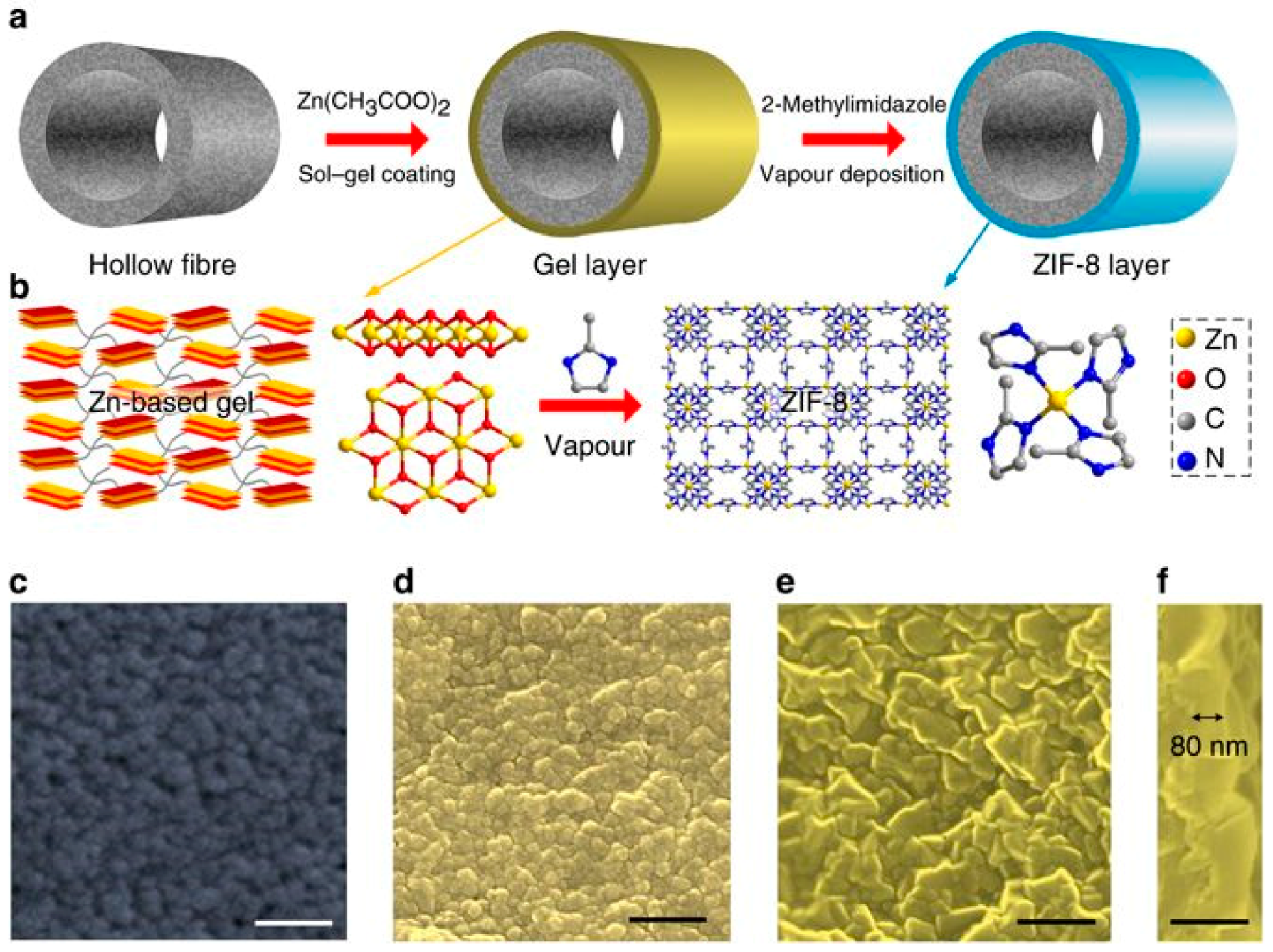
3.4. Gel Vapor Deposition Method

A gel–vapor deposition (GVD) method was introduced by Zeng et al. for MOF membranes fabrication. The method is based on combining a free sol–gel coating with a solvent-free vapor deposition [96]. Through this method, a better control over the thickness of MOF membranes can be achieved and, in some cases, a 20 nanometer-thick MOF membrane can be fabricated via the variation of sol concentrations and coating techniques. This method proved to bring several advantages like; the no need for pretreatment of supports prior to growth, compatibility between MOF and supports, low cost via the possibility to reuse MOF precursors, the facile handling of MOF layers locations, and shortening the time of fabrication. The GVD approach was applied to grow ultrathin ZIF-8 membranes by using a sol precursor, which is Zn-based, prepared via the mixing of zinc acetate dihydrate precursor and ethanolamine base in ethanol solvent. This support was then coated with sol precursor of 1 U concentration (in this study 1/3 g mL−1 of zinc acetate dihydrate/ethanol sol was defined as one concentration unit (U)) and thermally treated to form the Zn-based gel. Later on, this gel thin film was converted to the MOF membrane by the deposition of the ligand vapor by heating (Figure 13a). In this process, the produced ligand vapor reacts with the sensitive Zn-based gel thin film that leads to the crystallization of the MOF (Figure 13).

3.5. Vapor-Assisted Conversion Method

The vapor-assisted conversion (VAC) method was based on the modification of the dry-gel conversion and steam-assisted conversion approaches, developed previously, for the synthesis of bulk and thin films of zeolites and related compounds like ZIFs by Medina et al. [97]. This method is largely built on exposing a casted solution layer of one precursor to a vapor of another precursor of specific composition, at specific temperature, to convert it into a continuous and porous crystalline thin film of the targeted material (Figure 14). The VAC approach was proven to be an effective approach for the fabrication of MOF thin films, using different types of supports for different applications (e.g., Zr-based MOFs that were grown on-surface as thin films, in a highly oriented fashion [98,99]). Lately, VAC has been presented as a new efficient and gentle approach to fabricate covalent-organic frameworks (COFs) thin films [100].

3.6. Layer-by-Layer Method

The layer-by-layer (LBL) growth method, developed by Shekhah et al. in 2007, was successfully applied for fabricating thin films of HKUST-1 MOF [47,50,51,101,102,103]. The LBL growth method for growing MOFs is based on exposing of the support surface to the reaction precursors in an alternating approach involving rinsing the excess/unreacted precursors after each their exposure to the surface. Using this approach makes it possible to grow different types of surface-mounted MOFs (SURMOFs) on organic and oxide surfaces.
The LBL method was always used to fabricate MOF films on different substrates, but not as membranes [30,44,47,48,49,50,51,52,53,54,55,101,102,103,104,105,106]. In a recent work, the LBL was successfully introduced to fabricate homogenous ZIF-8 thin film on various supports, like porous silica and gold [51]. Consequently, the ability to control the film thickness and continuity has offered the possibility to apply the LBL technique for the fabrication MOF membranes on porous supports. Indeed, Shekhah et al. reported the implementation of the LBL method using a computer controlled dipping system (Figure 15) for growing a closed ZIF-8 membrane on alumina support Figure 16 [52].
Subsequently, an advanced LBL method for the construction of MOF membranes was introduced, based on the unique features of the traditional LBL method and the spin coating approach, for MOF membrane fabrication in a high-throughput manner Figure 17 [54]. In this work, a defect-free ZIF-8 membrane was grown using the LBL- spin coating approach and a porous alumina support, as shown in Figure 18.

4. MOF Membranes for Gas Separation Application

MOF-based membranes have recently attracted the attention of different research groups worldwide, as a promising candidate for many important gas separation applications [19,30,37,107]. The MOF membrane materials are based on their fabrication as thin films on porous supports, like alumina. This review emphases mainly on polycrystalline, pure and continuous grown MOFs membrane, which have been tested for the different gas separation applications. In the succeeding sections, we present many successful reported examples of MOF membranes used for different gas separations systems and discuss for each application the basic background and requirements.

4.1. Hydrogen Purification and Recycling

Nowadays, hydrogen (H2) is one of the trustworthy, viable, and environmental friendly energy sources, which could fulfill the world’s increasing energy requirements through its application as a highly dense energy source [108]. However, it co-occurs with other light gases such as N2, CH4, CO2, etc., in the course of production in many industrial processes. Consequently, there is a necessity for the development/improvement of advanced separation techniques to separate it from the above-mentioned impurities and get it as pure H2, which is the highly valuable fuel product. Provided optimal membranes are available, membranes-based separation offer a promising energy-efficient alternative to surpass the commercially applied highly energy intensive cryogenic separation [109]. Among other materials, zeolite-based membranes that are characteristic of its well-defined pore structures were fabricated by various techniques and investigated for H2 refining from exhausted gas streams [110,111]. Recently, MOF-based membranes were explored for this important gas separation; specifically, H2 recovery [112]. Here, we highlight some of the reported MOF membranes properties that are used for H2 purification and recycling.
The first MOF-based membrane was reported in 2009 by Liu et al. It consisted of a MOF-5 membrane fabricated using an in situ solvothermal method on top of an alumina support [56]. The single gas permeation properties were investigated, and the results demonstrated that they follow Knudsen diffusion behavior, where the gases with lighter molecular weight permeates faster than other gases, suggesting that the pore-aperture size of MOF-5 is larger than all of the tested molecules in this case. H2, which has the lightest molecular weight permeates faster than the heavier studied gases, like CH4, N2, CO2, and SF6. Later on, the orientation of the MOF-5 membrane was controlled by using a seeding approach and the subsequent solvothermal secondary growth on various porous substrates was achieved [62]. The associated single gas permeation results of the preferentially oriented MOF-5 membrane was found to have the same behavior that is consistent with the prior report.
HKUST-1 MOF (also known as Cu3(btc)2 or MOF-199) was fabricated as a membrane and it was grown using the ‘twin copper source’ solvothermal method [113]. HKUST-1 MOF has a structure with small cages having diameters of ca. 13 and 10 Å, accessible through windows of ca. 11 and 9.3 Å, respectively. The single-gas permeation of HKUST-1 membrane exhibited a high permeation flux, which is expected due to the wider pore-aperture size of HKUST-1 than the kinetic diameter of common studied gas. The permeation results also showed a permeation selectivity in favor of H2 with respect to other gases, such as H2/N2 = 7, H2/CO2 = 6.8, and H2/CH4 = 5.9.
Another HKUST-1 membrane prepared was grown through applying the LBL approach as a seeding layer at first and then followed by the in situ solvothermal method [73]. The single gas separation performances for this membrane were also evaluated and the ideal selectivities for H2 of this membrane were 2.9, 3.7, and 5.1 for H2/CH4, H2/N2, and H2/CO2, respectively. These ideal- selectivities clearly indicates that the permeation behavior of this membrane follows the Knudsen diffusion.
In another work, the HKUST-1 membrane was fabricated on a polymer functionalized stainless steel net-support using in situ solovothermal method by Zhu et al. [87]. This HKUST-1 membrane showed an enhanced ideal selectivities in favor of H2 for H2/CO2 = 9.24, H2/N2 = 8.91, and H2/CH4 = 11.2, in contrast to earlier studies. Later on the same group has successfully fabricated a continuous HKUST-1 membrane on pre-seeded, chitosan functionalized α-Al2O3 hollow ceramic fibers, through a secondary growth approach [114]. The fabricated membrane exhibited a slightly higher H2 selectivity of 8.66, 13.56, and 6.19 for the H2/N2, H2/CO2, and H2/CH4 gas mixtures, respectively (Figure 19).
The unique properties of ZIFs, in terms of permanent porosity, pore-aperture sizes uniformity, and good chemical and high thermal stability made them a good candidate for their application as molecular sieve membranes [115,116,117,118]. ZIF-8, is one of the most studied ZIF, has a sodalite underlying topology with a~3.4 Å aperture size for the six-membered-ring as the sole entrance to the associated pores, which would be theoretically, able to separate H2 from the other larger components [38,67,115,119]. Caro et al. fabricated the first ZIF-8 membrane via applying the in situ solvothermal method [120]. The membrane single-gas permeation results of this ZIF-8 membrane showed a higher H2/CH4 selectivity of 11.2, relative to earlier reported MOF membranes. Besides, Jeong et al. successfully fabricated a 1 μm thick ZIF-8 membrane exhibiting enhanced a higher ideal selectivities for H2/N2 and H2/CH4 of 11.6 and 13, respectively [71]. Later on, Caro et al. established a bicontinuous ZIF-8@GO membrane by applying the LBL method using a graphene oxide (GO) suspension on a ZIF-8 membrane to close the gaps between the ZIF-8 crystals in the thin film [86]. These ZIF-8@GO membranes exhibited a higher selectivity in favor of H2, at 250 °C and 1 bar, which were 14.9, 90.5, 139.1, and 3816.6 for H2/CO2, H2/N2, H2/CH4, and H2/C3H8, respectively, with a high H2 permeance of about 1.3 × 10⁻⁷ mol·m−2·s−1·Pa−1. Other groups fabricated other ZIF-8 membrane using the seeding method, LBL method and counter diffusion method, and the permeation results are in good agreement with the H2 selectivities reported earlier.
In a recent study, Caro et al. established a simple synthesis strategy for ZIF-8 membranes fabrication that was built on improving the support hydrophobicity by functionalization with a highly hydrophobic polymer, namely 1H,1H,2H,2H-perfluoroalkyltriethoxysilanes (POTS) (Figure 20) [121]. A high quality 20 µm thick ZIF-8 membrane was grown on the POTS-modified α-Al2O3 support, which exhibited a higher H2 selectivity and thermal stability. The mixture separation factors of different gases, like H2/CO2, H2/N2, H2/CH4, and H2/C3H8 were measured and were found to be 15.8, 22.6, 40.6, and 549.3, respectively, at 200 °C and feed pressure of 1 bar. The effect of temperature on the H2 permeance was investigated and showed that an increase in the temperature from 25° to 200 °C under same feed pressure of 1 bar, led to an increase in the H2 permeance accordingly from 1.4 × 10⁻⁷ to 2.3 × 10⁻⁷ mol·m−2·s−1·Pa−1, and an increase in the H2/CH4 mixture selectivity from 23.5 to 40.6. This is due to the fact that CH4 dominates the sorption at low temperature in the ZIF-8 pores, consequently hindering the H2 diffusion. However, at higher temperature, less CH4 can adsorb, and, consequently, more H2 permeates.
A counter-diffusion method to fabricate a ZIF-8 membrane as a composite on hollow fiber support membranes that was first functionalized with reduced graphene oxide (rGO) membranes via hydrothermal treatment was reported in [122]. Using this approach, 150 nm thin membranes were grown at the interfaces; gas permeation studies on these ultrathin ZIF-8/rGO membranes by Huang et al., showed an exceptional performance in H2 separation, as indicated by a high permeance of over 60 × 10−8 mol m−2 s−1 Pa−1 and selectivities for H2/CO2, H2/N2, and H2/CH4 of 25.3, 70.4, and 90.7, respectively (Figure 21).
In 2010, another ZIF membrane, ZIF-7, was reported by Caro et al. This membrane was grown using a microwave-assisted secondary growth approach; it has the same sodalite topology, like ZIF-8, but a small pore aperture [123]. ZIF-7 is a hydrophobic MOF with high thermal stability and a pore dimension that is smaller than ZIF-8 and almost similar to the size of H2, which is expected to achieve a higher H2 selectivity via molecular sieving. The single and mixed-gas permeation results for the fabricated ZIF-7 membrane were tested at 200 °C and 1 bar using the Wicke–Kallenbach technique and they are shown in Figure 22. The selectivities of the binary mixtures examined in this study for H2/N2, H2/CO2, and H2/CH4, were higher than Knudsen and found to be 7.7, 6.5, and 5.9, respectively.
The results indicated that the ZIF-7 sodalite structure with narrow pore aperture is accountable for this molecular sieving behavior. The non-zero permeance of gases larger than H2 was attributed to the imperfect sealing or presence of some defects. Later on, the 220 °C activated ZIF-7 membrane single gas and binary mixtures permeations tests revealed improved H2 selectivities with slightly change in permeances. The ideal selectivity and separation factor for H2/CO2 and other binary mixtures, like H2/N2 and H2/CH4, were higher than Knudsen.
ZIF-22, another ZIF isostructure with similar pore-aperture size like ZIF-7 (0.3 nm) was fabricated by Caro et al. as a membrane on alumina support functionalized with APTES to facilitate the MOF growth [83]. The ZIF-22 membranes gas permeation properties were evaluated and the separation factors of different mixtures, like H2/CO2, H2/O2, H2/N2, and H2/CH4 were tested at 323 K and found to be 7.2, 6.4, 6.4, and 5.2, respectively, with a H2 permeance of over 1.6 × 10⁻⁷ mol m−2 s−1 Pa−1.
ZIF-90, which has a structure like ZIF-8 and ZIF-7, which has a similar pore-aperture size of almost 0.35 nm, exhibit also high thermal and hydrothermal stability, was fabricated as a membrane on alumina support by Caro group [82]. The ZIF-90 membrane gas transport properties were evaluated and exhibited molecular sieve performance with a H2/CH4 and H2/CO2 selectivities of 15 and 7.2, respectively. The performance of this membrane was improved, via post-functionalization the membrane via imine condensation, which helped in enhancing the ZIF-90 H2/CO2 permselectivity from 7.2 to 62.5 by increasing the framework interaction with CO2.
ZIF-95 is another candidate from the ZIF family that has a poz topology, which has a 2.4 nm huge cavities, constricted aperture size (~0.37 nm) and excellent thermal stability up to 500 °C [124]. The sorption studies on pristine ZIF-95 showed that it has an extraordinary affinity and capacity for CO2 that can strongly adsorb CO2 and immobilized it in its big cavities. The H2/CO2 mixed gas selectivity was measured at 1 bar and it was found to increase from 8.5 to 25.7 with temperature increase from 25 °C up to 325 °C. This is explained by means of the higher affinity of the framework for CO2 at lower temperatures that lead to the blockage of the highly mobile gas since mainly CO2 was adsorbed as reported by Caro et al. (Figure 23). At higher temperature less CO2 will be adsorbed and thus H2 could diffuse more easily [125].
A continuous pure ZIF-67 tubular membrane fabricated by direct transformation of carbonate hydroxide nanowire arrays (Co-NWAs) in a 2-methylimidazole (Hmim) aqueous solution was reported [81]. The obtained ZIF-67 membrane exhibits a high H2 permeance of 5.59 × 10⁻⁷ mol m−2 s−1 Pa−1, and ideal selectivities for H2/CH4 and H2/N2 of 15.3 and 14.7, respectively. Figure 24 shows the gas permeation and separation values for pure Co-ZIF-67 tubular membrane for H2, CO2, N2, and CH4. The ideal selectivities for this membrane were found higher than Knudsen values for (H2/N2 = 14.7) and (H2/CH4 = 15.3). The separation factors through the pure Co-ZIF-67 tubular membrane for the mixed gas permeation of H2/N2 and H2/CH4 were 11.2 and 13.7, respectively. The gas permeances and separation factors in the mixed gas measurements slightly decreased when compared to those from single gases, which could be due to the adsorption competition of gases. The ZIF-67 membrane revealed a high H2 permeance of about 55.87 × 10⁻⁸ mol m−2 s−1 Pa−1, which is considered the highest with respect to the reported ZIF-8 membranes having the same isostructural sodalite topology. This was attributed to the good adhesion between the membrane and the support by using the Co-NWA layer as the Co2+ ions source, leading to the fabrication of a uniform and well-intergrown thin layer (1.7 μm) of ZIF-67. The influence of temperature was also investigated and showed that mainly the ideal selectivity to H2/CO2 has increased visibly with the increased temperature. This increase was attributed to the fact that the kinetic diameter of CO2 (ca. 0.33 nm) is much closer to the aperture of ZIF-67 (ca. 0.34 nm) than those of N2 and CH4, which are larger. The as-prepared ZIF-67 separation properties were tested by Lai et al. under different temperatures for the equimolar H2/CH4 mixture, as in Figure 24. Increasing the temperature from 30 to 150 °C, led to a slight enhancement in H2/CH4 separation factor from 13.7 to 15.4 and a decrease in H2 permeance from 45.32 × 10⁻⁸ to 32.47 × 10⁻⁸ mol m−2 s−1 Pa−1. This was explained by the difference in the adsorption and diffusion behaviors of H2 and CH4 in the ZIF-67 membrane.
ZIF-100 was also fabricated as a membrane on polydopamine-modified alumina support and was tested for its H2 separation properties. ZIF-100 has a composition of Zn20(cbIM)39(OH) (cbIM = 5-chlorobenzimidazole) and a moz topology with a pore-aperture size of 3.35 Å. The sorption studies on ZIF-100 showed that it exhibits an enhanced affinity and capacity to CO2 that led to an exceptional CO2 uptake [126]. The H2/CO2, H2/N2, and H2/CH4 mixture separation performance of this ZIF-100 membrane were evaluated at room temperature and 1 bar and their separation factors were found to be 72, 22, and 41, respectively, by Caro et al. (Figure 25). The high H2/CO2 selectivity is attributed to the extraordinary CO2 uptake behavior of ZIF-100 and its small 3.35 Å pore-aperture.
A composite membrane of ZIF-8-on-ZIF-67 and the neat ZIF-67 membrane were grown on ceramic α-Al2O3 discs by Caro et al., using the LBL approach [127]. Gas permeation of binary mixture experiments were conducted on pure ZIF-67 and ZIF-8-on-ZIF-67 membranes (Figure 26). The permeation test was performed from both sides, i.e., via either the ZIF-8 to ZIF-67 side or vice versa, in order to show that there was no difference in the membrane performance from both directions. Permeation results for different H2 gas mixtures with CO2, CH4, N2, ethane, ethylene, propane, and propylene were comparable (c.f. Figure 26b–h). The permeation results were measured for smaller gases, like H2/CO2, H2/CH4 and H2/N2, and H2/N2 the performance of the ZIF-67 membrane was similar to reported results for ZIF-8 membranes (Figure 26c). In case of H2/CH4 separation the ZIF-67 membrane performance is lower that ZIF-8, but still higher than Knudsen and in case of the ZIF-8-on-ZIF-67 membrane an improved separation performance was observed (Figure 26b). Finally, the ZIF-8-on-ZIF-67 separation performance for H2/CO2 separation (Figure 26b) was found better than the neat ZIF-67 and ZIF-8, and almost double the best reported values in literature. In the case of H2 separation from hydrocarbons, such as ethane, ethylene, propane, and propylene, the membrane separation performance was found to be higher than Knudsen but lower than the reported values in the literature (Figure 26e–h).
In another report, MIL-53, one of the highly stable related MIL MOFs was fabricated as a membrane. Jin et al. reported a densely-packed uniform MIL-53(Al) membrane grown using a seeding and solovothermal method (Figure 27, left) [91]. The permeabilities of the small gases revealed a permeation behavior that was similar to Knudsen. This was expected since the MIL-53 channel size is about 7.3 × 7.7 Å, and bigger than the kinetic diameters of tested gas (Figure 27, right).
A NH2-MIL-53(Al) membrane was fabricated on a glass frit macroporous support, using seeding method [128]. The adsorption results for this pristine material showed that the preferred functionalization of the MIL with the NH2 groups enhanced the adsorption affinity of particular gases and altered the gas interactions with the framework. Encouraged by these results, Zhu et al. also fabricated a NH2-MIL-53(Al) membrane. Permeation measurements, as shown in Figure 28, reveal a high selectivity of the membrane (over 20) for H2 over CO2.
MIL-96(Al) MOF possesses unique structural and hydrothermal stability features, up to 300 °C [129]. As a result, MIL-96 is a good candidate for H2 separation, like precombustion CO2, capture technologies. MIL-96(Al) was fabricated by Caro et al. as a membrane on ceramic alumina supports and tested for H2/CO2 mixed gas separation. Figure 29 shows the permeation performance for MIL-96(Al) membrane, which showed that the 2 μm thick membrane has a lower permeance than the 8 μm one. This finding attest to the impact of growth orientation of the MIL-96(Al) crystals in the membrane layer on the separation properties.
The MIL-96(Al) membrane fabricated from the toluene/water seeding, form (0k0)-equivalent facets that allow a faster diffusion. The higher permeance of this thicker membrane (toluene/water seeded), 100% higher than the thinner one from DMF/water seeded, is the result from the variation in ratio of the crystals orientation in the membrane. In the case of a DMF/water-seeded MIL-96 membrane, the pathway of the gas through the outer lattice planes, are blocked, since this MOF is virtually a two-dimensional (2D)-network. A MIL-96(Al) structure allows an easier diffusion in the a-direction (i.e., perpendicular to bc planes) and b-direction (i.e., perpendicular to ac planes); however, in the case of the c-direction (i.e., perpendicular to ab planes), it is slower (Figure 29b).
Later on, in 2016, Friebe et al. fabricated a thin NH2-MIL-125 MOF membrane and tested its separation performance for a H2/CO2 gas mixture with equimolar ratios, at different temperatures [130]. They also performed permeation tests by varying feed pressures (3, 4, and 5 bar) at 150 °C, in order to simulate the pre-combustion process for the capture of CO2. The presence of free amine groups in the NH2-MIL-125 MOF is expected to enhance the framework’s affinity for CO2, and, as a result, improve the separation of H2 and CO2. Indeed, the NH2-MIL-125 membrane that was fabricated by Caro et al. showed a H2 permeability almost eight times higher than that of CO2, at room temperature (Figure 30).
The H2 permeability, in single gas permeation measurements, is slightly higher than the mixed gas measurements, indicating the absence of strong adsorptive interactions between H2 and the framework. However, in the case of CO2, single gas permeation results are almost double the mixed gas one, which is attributed to the stronger affinity of CO2 molecules with the restricted number of NH2 functional groups in the framework.
Li et al. used the MOF transformation for bulk and applied it to membranes [131]. In this case, the CuBTC membrane, fabricated on a hollow fiber polymeric support, was applied as a sacrificial layer for the transformation to MIL-100 membrane. Figure 31a–c shows the SEM images of the original CuBTC membrane and the CuBTC/MIL-100, as-synthesized, and after purification. After post-transformation, the CuBTC/MIL-100 membrane (as-synthesized) became denser due to the presence of a FeCl3 residue. However, after the removal of the residue, and with a transformation period extended to 48 h, a complete transformation to MIL-100 was achieved. The gas separation performance of transformed MOF membranes, for H2, CO2, etc., was investigated. Figure 31d,e shows the permeance and selectivities of the different gas mixtures with H2 for the neat CuBTC and transformed CuBTC/MIL-100 membranes. Results revealed smaller permeances values of all gases for the transformed CuBTC/MIL-100 membranes than for the neat CuBTC membrane, and H2 had the highest permeance of 8.8 × 10⁻⁸ mol m−2 s−1 Pa−1. In case of selectivities, they showed a good improvement in case of H2/CO2, H2/O2, H2/N2, and H2/CH4 that were found to be 77.6, 170.6, 217.0, and 335.7, respectively. The effect of temperature on the selectivities was investigated and was found to increase and has reached 89.0 for H2/CO2 and 240.5 for H2/N2, with temperature increase to 85 °C. Additionally, the H2 permeance increased to 10.5 × 10⁻⁸ mol  m−2  s−1  Pa−1 with the temperature increase (Figure 31f). The performance of the transformed MIL-100 membrane was found to be better than most reported membranes for separation systems, like H2/CO2, H2/N2, and H2/CH4.
An aluminum- based MOF, namely CAU-10-H (CAU stands for Christian-Albrechts-University, Kiel, Germany), was fabricated by Yang et al. as a membrane, using an in situ solvothermal method [132]. The gas separation performance of this membrane was studied for ternary mixture of H2/CO2/H2O under different feed pressures and temperatures. The gas permeance with respect to gas molecular size reveal a permeance cut-off edge for gases larger than H2, which is due to the size-exclusive molecular sieving of the membrane. The selectivities for the mixed gas measurements for H2/CO2 was 10.5 and for H2/CH4 was found 74.7, which are higher than Knudsen. The H2 permeance in case of H2/CO2 binary mixture was found to be lower than the H2/CH4 one, due to the blocking effects that are caused by the strongly adsorbed CO2. The increase in temperature or feed pressure led to an enhancement in the H2 and CO2 permeances and a reduction in the selectivities Figure 32.
A dense and continuous membrane of Mg-MOF-74 was fabricated by Caro et al., using a seeding method of magnesium oxide, and tested for hydrogen separation Figure 33 [77]. The measured single gas permeances of this membrane showed a H2 permeance of 1.2 × 10⁻⁷ mol m−2 s−1 Pa−1 Figure 34. The H2/CO2 mixture separation factor was the highest, as compared to other mixtures, such as H2/CH4 and H2/N2 (inset in Figure 34).
The mixed gas selectivities of the H2/CO2 mixtures were improved by ethylenediamine post-modification of the Mg-MOF-74, due to the increased adsorption affinity for acidic CO2 molecules as a result of the introduction of an amine group. After post-functionalization, the H2/CO2 selectivity increased from 10.5 to 28 (Figure 35).
Using the LBL seeding approach and a solvothermal secondary growth method, a continuous Ni-MOF-74 membrane was fabricated on a α-alumina support [78]. The gas permeation of the fabricated membranes was tested for gases, like H2, N2, CH4, and CO2. The CO2 permeation was found to be the lowest, due to the stronger adsorption affinity for CO2, resulting in a high ideal selectivity for H2/CO2 for this membrane.
Layer-pillar based MOFs structures can also be tuned to create isoreticular structures with different pore sizes via tuning the length of the pillars, like, for example, the Cu(bipy)2(SiF6) MOF, which showed an extraordinary CO2 sorption selectivity over other gases, like N2, H2, and CH4, even under humid conditions [133]. This Cu(bipy)2(SiF6) MOF was successfully fabricated by Zhu et al., as a membrane, using an in situ solvothermal synthesis method. The fluoridation of the support by (NH4)2SiF6, using SiF62− as a source, promoted the growth by promoting the connection between the membrane and support. The H2 permeation tests with respect to other gases showed separation factors of 8.0, 7.5, and 6.8 for H2/CO2, H2/CH4, and H2/N2, respectively. The membrane showed a high H2 permeance of 2.7 × 10⁻⁷ mol m−2 s−1 Pa−1 and an excellent thermal stability (Figure 36).
Takamizawa et al. [135] reported the fabrication of an oriented membrane, obtained from a single-crystal of [Cu2(bza)4(pyz)]n MOF, with a high permeance one-dimensional (1D) channels. This membrane displayed an anisotropic gas permeation via the 1D channels, and a high permselectivity for H2 and CO2. Although the channels are contracted with a narrower pore-aperture size, smaller than the kinetic diameters of the gases previously tested-, many of them were able to pass via these 1D channels (Figure 37). Permeability values that were measured along the channels were found to be 7–60 times more than those measured perpendicular to the channels. The permeability measured perpendicularly to the channels, for several gases at 293 K and a differential pressure of 50 KPa, were undetectable. Results showed that He, H2, and CO2 gases permeated slightly faster when they are in the orientation perpendicular to the channels, which could be related to a minimum number of crystal defects in this route. This clearly indicates the possibility for the gases to permeate through the membrane channels, even though the channel aperture size is smaller than the kinetic diameters of the tested gases (Figure 38).
The [Ni2(L-asp)2(bipy)] MOF (L-asp = L-aspartic acid, and bipy = 4,4′-bipyridine), a chiral MOF was investigated by Qui et al. where the pores in this parent MOF were altered by employing a shorter pillar like pyrazine (pz). As expected, this isostructural MOF with the same framework topology [Ni2(L-asp)2(pz)] (named JUC-150, JUC=Jilin University China) was successfully synthesized and structurally characterized Figure 39 [136]. This ultra-microporous JUC-150 membrane exhibited a favored permeation of H2 against other tested due to its excellent size sieving properties, which enhanced its selectivity performance from 26.3, 17.1, and 38.7 for the case of H2/CH4, H2/N2, and H2/CO2, respectively. These values are among the best separation selectivity values obtained with MOF membranes. In addition, the JUC-150 membrane showed an outstanding thermal stability separation performance at higher temperatures (e.g., 200 °C) (Figure 40 and Figure 41).
Covalent organic frameworks (COFs), represent a subclass of the porous materials that consist of strong covalent bonds between light elements, like C, B, N, etc. These porous materials are credited with excellent structural tunability and stability and low density. Recently, COF-MOF composite membranes were fabricated by Qiu et al. and tested for the H2 separation from CO2 [137] (Figure 42 and Figure 43). Their excellent performance, in terms of very high selectivity when compared to the neat COF and MOF membranes, has surpassed the Robeson upper bound for other materials, like polymer-based membranes for this separation. The separation factors for the H2/CO2 (1:1) binary mixture for two composite membranes form [COF-300]-[Zn2(bdc)2(dabco)] and [COF-300]-[ZIF-8] were found to be around 12.6 and 13.5, respectively (Figure 44). This noteworthy performance is attributed probably to the fabrication method, which implicates the strong chemical bonding induced between the support, COF, and MOF, since the COF material can cooperate via imine groups with polyaniline, while in case of the ZIF, the HN-Zn-imidazole bonds could help in sealing the interface with the COF.
There has been an increasing interest in two dimensional (2D) MOF nanosheets,, due to their unique properties, such as large surface areas, nanometer-sized cavities, uniform channels, stability, and chemical tunability, which make them potential candidates for applications in membrane gas separations [138,139]. Zhang et al. fabricated a highly oriented tubular membrane of Zn2(bIm)4 (bIm = benzimidazole) ZIF nanosheet was fabricated by using the self-conversion of ZnO nanoparticles (NPs), and following a graphene oxide (GO) guided method (Figure 45) [122].
An oriented nanosheet tubular membrane that was fabricated by solvothermal growth over a 9 h period (denoted as M-9) was tested for its single and binary mixtures gas permeation performances. Figure 46, which displays the permeances of H2, N2, CO2, and CH4, shows that H2 has the highest one and Ideal selectivities were 106, 126, and 256 for H2/CO2, H2/N2, and H2/CH4, respectively, all higher than Knudsen’s selectivity. Binary mixtures through the M-9 membrane confirmed the very good molecular sieve performance of this M-9 membrane; separation selectivities for H2/CO2, H2/N2, and H2/CH4 were found to be 89, 103, and 221, respectively.
In their experiments, they found that changing the feed partial pressure for H2 from 0.5 to 1.5 bar did not affect the gas permeances or the H2/CO2 separation selectivity, thus proving an excellent mechanical stability (Figure 46). The increase in the testing temperature from 30 to 150 °C did not affect significantly the permeation, neither for H2 nor for CO2. However, the H2 permeance and separation selectivity of H2/CO2 increased slightly (Figure 46b). This is could be due to some structural flexibility of the nanosheets, resulting in a slight increase in their effective pore size. This small change of pore-aperture size slightly affected the permeance of H2 (small kinetic diameter) and barely influenced the permeance of CO2 (larger kinetic diameter), resulting in a very small improvement of the separation selectivity of H2/CO2.

4.2. MOF Membranes for CO2 Separation

Carbon dioxide (CO2) is considered as the main contributor for greenhouse gas emissions, and its continuous concentration buildup in our atmosphere is expected to produce severe global warming. CO2 is known to be one of the main impurities in natural gas and needs to be separated before the gas is pumped to the pipeline, in order to prevent major corrosion issues. Thus, it is of great importance to develop processes that effectively separate and recycle CO2 from these different natural gas sources [140]. Membrane-based separation technology is considered as a promising alternative to the conventional separation processes, since it is more energy-effective route and highly reliable. Therefore, many materials, such as polymers and zeolites, have been developed as membranes for the separation of CO2. However plasticization decreases the performance of polymers while zeolites suffer from low permeability [2,13,141,142,143].
Rationally, various MOFs have been explored as membranes and applied to separate CO2 from other common gases such as CH4 and N2. Among these MOFs are ZIFs, which possess a porous framework with accessible pore systems and wide-ranging pore-aperture sizes [115,144]. The pore-aperture size of different ZIFs, as an example in ZIF-8, lies within the kinetic diameter range of common gas molecules. Moreover, ZIF-8 is a chemically stable material, even in the presence of water and some aromatic hydrocarbons, like benzene, the classic impurities in natural gas refining, making this MOF a potential candidate for separating CO2 from CH4 [67,117,119,145].
Carreon et al. fabricated ZIF-8 membranes via the in situ solvothermal method on tubular alumina supports that were functionalized via hydrothermal seeding [67]. In their study, all of the fabricated membranes displayed a high CO2 permeance of ~2.4 × 10⁻⁵ mol m−2 s−1 Pa−1 and a selectivity for CO2/CH4 of ~4–7. The density functional theory simulation data on ZIF-8 suggested that the ZIF-8 smaller pores were the favored adsorption spots for CO2, over CH4.
Achieving the molecular separation of CH4 and CO2 is complex, due to the similarities in their molecular sizes in a membrane-based process. Advantageously, the tunable composition of MOFs, based on a wide-range of metal ions and organic ligands, made it possible to selectively adsorb these two gases, offering the prospect to a CO2 separation from CH4 through a sorption-based separation mechanism.
Continuous membranes of Co3(HCOO)6 MOF were fabricated on a macroporous glass support by Mintova et al. (Figure 47) [146]. The overall framework of the Co3(HCOO)6 MOF has a 1D zigzag channels with an aperture size of 5.5 Å. This channel structure was found to favor CO2 separation from CH4 via preferential adsorption. As shown in Figure 48, the microporous Co3(HCOO)6 membrane showed a high permeation flux of 2.09 × 10⁻⁶ mol m−2 s−1 Pa−1 and an outstanding permeation selectivity for CO2 over CH4 of 10.37–15.95 at 0–60 °C. This is because CO2 molecules permeate faster through the 1D zigzag channels as compared to CH4. This faster permeation of CO2 was a result of the preferential adsorption of CO2 in the micropores and external surfaces of the MOF membrane, which suppressed CH4 sorption from the mixture. These results revealed that the suitable pore size, combined with the right pore shape, in the case of the Co3(HCOO)6 MOF, can prevent the two molecules to permeate through it simultaneously, i.e., once CO2 permeates through the pores, the permeation of CH4 molecules is hindered.
The orientation of fabricated membranes has shown to influence their separation performance. Highly oriented MOF membrane of ZIF-69 was reported for gas separation by Lai et al. [147]. The ZIF-69 possessed a zeolite gme topology with 12 and 8 membered ring (MR) channels along the c-axis and the a- and b-axes, respectively. The pore-aperture size along the c-axis is about 0.78 nm, which means that, in order to achieve an outstanding gas permeation performance, it is required to fabricate a c-oriented ZIF-69 membrane, which will have the straight channels line up perpendicular, with respect to the support surface. The ZIF-69 membranes were fabricated by using oriented seeds at first and then a secondary growth step (Figure 49). The single-gas permeation results of N2, CO2, and CH4 showed that they possess a Knudsen behavior, whereas in the case of the CO2 permeation, it was dominated by surface diffusion as a result of the high adsorption affinity of ZIF-69. The separation of equimolar gas mixture of CO2 and N2, CO, and CH4 were measured and found to be 6.3, 5.0, and 4.6, respectively, with a permeance of ~1.0 × 10⁻⁷ mol m−2 s−1 Pa−1 for CO2 (Figure 50 and Figure 51). A comparison of the non-oriented grown ZIF-69 with the c-oriented ZIF-69 membrane showed that the oriented one had a better selectivity and higher permeance.
Recently, the LBL method was used by Caro et al. for the fabrication of membranes of [Cu2(ndc)2(dabco)] or [Cu2(BME-bdc)2 (dabco)] [148]. The [Cu2(ndc)2(dabco)] is a MOF with a large-pore where no affinity exists between the gases and the framework. As expected with such systems, they were found to follow the Knudsen behavior. However, in case of the BME-bdc, which is composed of a benzene ring functionalized with two ether side groups (O(CH2)2OCH3), which are expected to enhance the framework affinity toward CO2 in [Zn2(BME-bdc)2 (dabco)] MOF. The fabricated membrane of [Cu2(BME-bdc)2-(dabco)] has shown a higher selectivity toward CO2, as compared with CH4. The gas mixtures tests of equimolar CO2/CH4, exhibited a 4.5 selectivity factor that is higher than the corresponding Knudsen coefficient. The separation cannot be credited only to the molecular sieving effect, since the flexibility of the ether groups makes it difficult to estimate the effective pore size. The enhanced affinity of the framework for CO2 is also a contributing factor (Figure 52).
Bio-MOF-1 membranes were prepared using a secondary seeded growth method and tested for gas mixture separation, by Carreon et al. [149]. These Bio-MOF-1 membranes exhibited high CO2 permeances and separation selectivities over CH4. The measured CO2/CH4 separation selectivities were higher than one, therefore higher than the Knudsen selectivity. The CO2 preferential adsorption in this MOF, driving separation mechanism, was credited to the existence of organic ligand amino basic sites in the Bio-MOF-1 structure. The Robson plot showed that the Bio-MOF-1 membrane exhibited the same performance as most conventional polymeric membranes, however less than most zeolite membranes (Figure 53).
Later on, the same group reported the fabrication of cobalt–adeninate MOF (bio-MOF-13 (I) and bio-MOF-14 (II)) membranes [150]. The fabricated membranes exhibited high CO2 permeabilities and low CO2 separation selectivities over CH4. These observed high CO2/CH4 selectivities were credited to the favored CO2 adsorption in the case of the bio-MOF-13 framework. These membranes displayed CO2 permeances as high as 4 × 10⁻⁶ mol m−2 s−1 Pa−1 with CO2/CH4 separation selectivities in the 3–4 range at 295 K (Figure 54). The enhanced CO2 adsorption in these frameworks was again attributed to the presence of basic linkers, although the type of this specific nature between the CO2 and framework is unclear.
Recently, Jeon et al. also used a rapid one-pot solvothermal microwave growth approach to fabricate a mixed-linker ZIF membranes [66]. The mixed-linker ZIF consisted of the ZIF-8 linker the 2-methylimidazolate (mIm) and the ZIF-7 linker the benzimidazolate (bIm), and these were termed as the ZIF-7-8 membranes (Figure 55). Using this rapid synthesis approach, they were able to alter the ZIF-7-8 membranes separation properties by varying the ratios of bIm to mIm linkers in the mixed linker frameworks. The permeances of H2, CO2, N2, and CH4 were reduced, and the ideal selectivities increased with increasing the bIm/mIm ratios. The mixture gas permeation study for H2/CH4 and CO2/CH4 on ZIF-7-8 membranes showed an enhancement in selectivity, when increasing the bIm linker ratio, suggesting the change in the separation behavior of the membrane with the variation of the linkers ratios (Figure 56).
Upon comparison with the mono linker neat ZIF membranes, like ZIF-7 and ZIF-8, the mixed linker ZIF-7-8 membranes still shows a reasonable performance for both H2/CH4 and CO2/CH4 gas separations, which indicates the good quality of ZIF-7-8 membranes (Figure 57).
The post- and precombustion carbon capture and natural gas upgrading applications are very important separation applications. However, few studies on the application of MOF membranes for the CO2 gas separations from N2, CH4, and H2 have been reported to this day. An efficient membrane for the capture of CO2 from N2, CH4, and H2 gas feeds, should provide an excellent separation for CO2 over other gases, in order to concentrate these valuable gases, such as CH4, O2, and H2 more efficiently. According to the literature, the separation selectivity that favor CO2 permeation was first reported using [Cu2(bza)4(pyz)]n as a single crystal MOF membrane [135].
Later on, Lin et al. reported thin MOF-5 membranes that were fabricated by a secondary growth method [151]. They investigated the permeation and separation features of this membrane towards mixtures of CO2/H2 and CO2/N2. The MOF-5 membranes were tested with CO2/H2 or CO2/N2 mixture feed, showed a more permeability to CO2 over H2 or N2. The CO2/H2 separation factors were more than 1, i.e., CO2 was more permeable not H2. This is related to the fact that MOF-5 has a favored adsorption of CO2 over H2, as derived from a saturated sorption capacity of 2 mmol/g for CO2 and 0.1 mmol/g for H2 at 298 K and 1 atm). In their experiments, Lin et al. used a post CO2 annealing means and successfully increased both the permeance and separation factor of MOF-5 membranes for the CO2 separation over H2 [152]. The post-treatment of the membrane (PMOF-5) was performed by annealing the MOF-5 under a high pressure CO2 stream at 100 °C, which led to a decrease of the H2 permeance and an increase of the CO2 permeance, and resulting in an improvement of both CO2 and H2 separation factors from 721 to 5781 and an improved CO2 permeance from 5.67 × 10⁻⁷ up to 9.38 × 10⁻⁷ mol m−2 s−1 Pa−1 under CO2 molar fraction of 98%, feed pressure of 5 atm and 298 K Figure 58. The uncommon separation performance is again related to the enhanced CO2 adsorption selectivity over H2 and the formation of surface carbonate anions caused by the CO2 treatment. The separation factor of CO2/H2 for the no post-treated membrane (PMOF-5) increases drastically from ~2 at a below 0.94 sharply to about 721 at an of 0.985 and CO2 permeance of 5.67 × 10⁻⁷ mol m−2 s−1 Pa−1, and then deceases with a further increase in CO2 mole fraction.
Recently, the first zeolite-like MOF (ZMOF) membrane with a sodalite topology was prepared via a solvothermal crystallization approach on porous alumina support [153]. ZMOFs were pioneered by Eddaoudi et al. and they represent a subclass of MOFs, which are topologically related to pure zeolites. ZMOFs exhibit unique properties, like extra-large cavities, chemical stability, and anionic character amenable to cation exchange. Their anionic character allows the tuning of the pore system via extra-framework cations exchange, which, in turn, tunes their host–guest interactions. The sod-ZMOF-1 is made from the reaction of In3+ cations and imidazoledicarboxylate (ImDC2–) linkers with the help of a structure directing agents (SDAs).
The sod-ZMOF-1 incorporates large β-cavities, which are only accessible via 6MR windows having a 4.1 Å diameter pore-aperture size, whereas the 4MR window are not accessible. The sod-ZMOF-1 6MR narrow size is expected to provide some selective diffusion and thus to allow for the separation of small molecules, versus larger ones. Furthermore, the sod-ZMOF-1 anionic character will affect the adsorption/diffusion of some gases molecules, which, in turn, will alter its permeation and separation properties. The single gas permeation results show a high CO2 permeability and higher ideal selectivities in favor of CO2 over other gases above Knudsen (Figure 59 and Figure 60). The calculated values of separation factors were 8.7 for CO2/N2, 5.1 for CO2/O2, and 3.6 for CO2/CH4. The gas mixture permeation experiments confirmed the preferential CO2 selective permeation for CO2/CH4), and CO2/N2 of 4 and 10.5 (at 3.4 bar), respectively. In the case of the CO2/H2 mixture, the CO2 permeability was faster than H2 and the ideal permeation selectivity for CO2/H2 was 2.6. The CO2/H2:30/70 mixture permeation confirmed that the CO2/H2 observed reverse-selectivity and showed a 5.2 CO2/H2 selectivity. This enhancement in the mixed-gas permeation selectivity, was attributed to the favored CO2 adsorption over H2. Supplementary permeation tests at different temperatures confirmed these results, where the selectivity of CO2/H2 decreased with increasing the temperature, and vice versa.

4.3. Hydrocarbons Separation

The hydrocarbon gas mixtures separation is considered as one of the most energy-intensive process in different industrial sections, like petroleum refining, petrochemical, and natural gas production. Nowadays, petrochemical refineries need to separate hydrocarbon mixtures on a huge scale to produce fuels and chemicals for the market. For example, the cryogenic distillation process for paraffin/olefin separation is considered as the most energy and cost demanding practices [154]. In the production of propylene, the cost comes from the difficulty of separating it from propane due to their similar boiling points. The course of industrial distillation demands about 200 separation trays, which makes it one of the most energetically costly processes in the petrochemical industry [155]. The same applies to C4 isomers, such as butane and isobutane, for which the physical properties are also similar. Thus, the separation of such compounds by distillation is extremely costly. Alternatively, energy efficient membrane-based separation offers the possibility to reduce the cost of separation. Thus far, different types of membranes were tested for these types of separations, including polymers, zeolites, carbon molecular sieves, and mixed matrix materials. However, most of them have drawbacks that limit their performance [156,157]. In the case of polymeric membranes, they suffer from plasticization. This process refers to a change of polymer structure, and thus, a loss in its separation performance that is caused by the swelling of the space between polymer chains, as a result of the adsorption of CO2 and other hydrocarbons, which decrease the durability of polymer membranes. Additionally, Zeolites, carbon molecular sieve and mixed matrix membranes although have shown better performance in terms of selectivity/permeability as compared to the polymers, but they still require optimization of their preparation procedures and new membrane-modules designs [158]. Notably, advanced performing materials should be discovered in order to justify the investments into the changes of well-established distillation industry. Additionally, carbon based membranes are extremely fragile, which makes their scale-up even more challenging than other prospect materials [159].
Great diversity of pore environments and geometries in MOFs affords various types of adsorption-based separations. In an excellent recent review, Adil et al. have highlighted major achievements made in the field of adsorption-based separation, highlighting the advances that have been made with MOFs in the area of hydrocarbon separation [37,160]. Prominently, MOFs have been also examined in a form of membranes.
Recently Caro et al. fabricated a 25 μm thick ZIF-8 layer on asymmetric titania support (Figure 61) and used the measured permeation selectivity for ethane/ethylene separation for a correlation study with the grand canonical Monte Carlo simulations and infrared microscopy, diffusion and adsorption data [145]. The ethylene/ethane separation factor α dependency on pressure were investigated. By increasing the gas feed pressure, a slight decrease in separation factor from 2.8 to 2.4 was observed, as in Figure 62. The single gas permeation without applying a sweep gas showed an ideal separation factor of 4.2. The dissimilarity in separation efficiency observed between the single gas and the mixed gas measurements were attributed to the difference in experimental conditions. Later on, the transport properties of ethane/ethylene separation in the same (ZIF-8) membrane were studied by James et al. at different temperatures ranging from 25 to 100 °C and different pressures [161].
In the case of propane/propylene separation system, a propylene permeability of 1 Barrer and a selectivity of 35 are the minimum requirement for the deployment of a membrane for commercial application. Accordingly, the innovative material development are vital to effectively fulfill the requirements for this highly energy-intensive important separation [2]. The separation of propylene and propane using ZIF-8 membranes was first reported by Li et al. and it was based on the kinetic separation revealed from adsorption studies on ZIF-8 powder [157]. Although the size difference is around 0.02 nm between these two gases, the reported selectivity was 150.
Jeong et al. reported a one-step in situ synthesis procedure for the fabrication of high-quality ZIF-8 membranes using counter diffusion method [69]. The fabricated membranes were tested for the separation of a propylene/propane (50/50) mixture and they revealed a high separation selectivity of ~55. Figure 63 shows these ZIF-8 membranes propylene/propane separation performance that were fabricated at room-temperature with variable growth times. The increase in the membranes growth time increased the separation factor, however reached a plateau after 1 h. The separation factor and the propylene permeability of these ZIF-8 membranes outperformed the values that were reported for polymeric and zeolite membranes (Figure 64).
In another study high-quality ZIF-8 membranes were fabricated using rapid thermal deposition method by Jeong et al. [162]. The separation of propylene/propane tests for these membranes were found to exhibit a selectivity of ~30. Later on, using a rapid and simple microwave-assisted seeding technique, they managed to synthesis high-quality ZIF-8 membranes that showed an enhancement in the propylene/propane selectivity of ~40.
Hara et al. used the counter diffusion approach to fabricate an 80 μm-thick ZIF-8 layer on a alumina capillary support [163]. They have managed to isolate the contribution of the diffusive separation for propylene/propane from the permeation features of these membranes. The single- gas permeation for C3H6 and C3H8 were measured at temperatures from 298 to 363 K. The ideal separation factors for C3H6/C3H8 at 298 K were found to be 59. The analysis of the permeation results show that the diffusion separation factor increases to 23 by reducing the temperature, whereas the solubility separation factor of 2.7 does not change, indicating that the separation of propylene/propane is mainly driven by diffusive separation.
In another study by Lin et al., ZIF-8 membranes were fabricated using a secondary growth method in water, and were tested for the separation of C3H6/C3H8 [164]. Measurements of the single gas permeance for C3H6 and C3H8 showed a decline when pressure was increased, suggesting the pressure reliance on the adsorption isotherms for individual gas. The ZIF-8 membranes showed a high C3H6/C3H8 selectivity of 30 and a high C3H6 permeance of 1.1 × 10⁻⁸ mol m−2 s−1 Pa−1 when an equal-molar binary feed was used (Figure 65). The C3H6/C3H8 selectivity decreased with increasing feed pressure and temperature, while permeance also decreased when the feed pressure was increased. The stability and durability tests on these membranes for over a month showed a stable performance.
Additionally, Nair et al. reported the fabrication of ZIF-8 membranes using an interfacial microfluidic membrane- processing technique in engineered polymeric hollow fibers (Figure 66) [165]. Under optimized synthetic conditions, these hollow fiber membranes exhibited a separation factor of approximately 180. Such an excellent separation even remained high (separation factor of 60), at 120 °C. These membranes were tested under high-pressure operation conditions; results showed a four-times enhancement in the flux and an excellent C3H6/C3H8 separation factor of 90, at 9.5 bar. These membranes also exhibited a long-term stability in permeance and selectivity, under testing operations over a month-period (Figure 67).
In another study, Nair et al. fabricated ZIFs membranes on carbon hollow fibers using the fluidic processing technique [166]. The resultant ZIF-8 membranes were tested for dehydration of ethanol and furfural, while the ZIF-90 was tested for the butane isomer separation. The measured permeability of butane in ZIF-90 was comparable to the predicted data (192 vs. 206 Barrer), while the selectivity was significantly lower, indicating the presence of defects (7000 vs. 12). Nevertheless, the described membrane, to the best of our knowledge, is the only pure MOF membrane study reporting the separation of butane isomer mixtures.
The separation of condensable hydrocarbons (e.g., C2H6, C3H8, and n-C4H10) from supercritical CH4 is an important industrial process in the upgrading of natural gas. Recently, Shekhah et al. showed that n-C4H10 exhibit an extremely slow adsorption kinetics in ZIF-8 in comparison to other hydrocarbons, like C3H8 and C2H6 [53]. The study showed that there is a real adsorption kinetic cut-off at 4.8–4.9 Å, which is the Lennard-Jones diameter of n-C4H10. Accordingly, for the first time the CH4/n-C4H10 mixture separation properties on ZIF-8 membrane were explored. The ZIF-8 membrane exhibited a high selectivity (ca. 250) for CH4 using a 75/25 CH4/nC4H10 feed, in the first 2–4 h of the experiments, which showed then a rapid decrease with time and exhibited a selectivity of 4 at the steady state after 30 h (Figure 68). The analysis of the permeation results showed that the permeability of n-C4H10 increased from 0.01 Barrer at 6 h to 0.35 Barrer after 30 h, leading to a partial blocking of the CH4 transport in the membrane, as revealed form the 40% drop in its permeability. A noticeable enhancement (from 4 to 16) in the selectivity of CH4 in the mixture separation was achieved by increasing the temperature up to 323 K, at a constant feed pressure.
The exciting separation features of the soc-MOF platform has motivated Belmabkhout et al. to fabricate them as membranes and evaluate their gas transport separation properties in particular for refinery-off gases [167].
The in situ solvothermal approach was used for the growth of highly crystalline and closed Fe(III) and Al(III) soc-MOF analogues as membranes, as proven by XRD and SEM in Figure 69. The single gas permeation properties for the Fe-soc-MOF membrane were studied and evaluated using the time-lag method. The single gas permeation results for diverse gases, like H2, O2, N2, CH4, CO2, C2H4, C2H6, C3H6, C3H8, and C4H10 were measured and the Fe-soc-MOF membranes was found to exhibit a decrease in permeability as the Lennard-Jones diameter of the gases increased from H2 to CH4 (Figure 70 (left)). However, in the case of hydrocarbons the permeability was found to increase with increasing the boiling point of the gas increased, (Figure 70 (right)). The derived solubility and diffusivity coefficients from the permeability and the time lag measurements revealed a rise in the permeability of C2+ hydrocarbon, suggesting a predominance of the solubility factor. The permeation of the ROG constituents followed the Knudsen behavior, though a high n-C4H10/CH4 adsorption selectivity was observed for the pristine Fe-soc-MOF-1b, however, the selectivity of the Fe-soc-MOF-1b membrane was only 2.2. This behavior is due to the somewhat large aperture size of the 1D channels in the soc-MOF.

5. Discussion

As the foremost limitation for preventing the usage of polymers in the area of carbon dioxide and hydrocarbon separation is plasticization, the rigid membranes with uniform pore structures, such as made from MOFs, are expected to be more effective than polymers [168]. The robustness of these microporous materials affords the unremitting permeability of the gases, while the uniformity of the pore windows controls the passage of certain gases over others. Depending on the size and environment of the MOF structure toward the targeted gas, the diffusion- or sorption-controlled selectivity can be achieved, as evidenced by the analysis of the reported research articles concerning H2/CO2 separation (Figure 71).
The majority of MOF-based membranes are reported to act as molecular sieves that possess higher permeabilities for the relatively smaller hydrogen molecules, as compared to the larger ones, like carbon dioxide, due to the dominant diffusion component of H2 (Figure 71a). The selectivity of such membranes often does not undergo significant changes, upon increasing the temperature or by varying the composition of mixed gases (versus single gases). It should be noted that the performance of MOF-hydrogen selective membranes is significantly higher than the performance of reported polymers in the open literature, suggesting their great prospects for hydrogen purification.
The CO2 gas separations from N2, CH4, and H2 using MOF membranes were also investigated and only few examples have been reported. An efficient membrane for application should reveal an excellent separation selectivity for CO2 over other gases, in order to be able to concentrate these valuable gases such as H2 more efficiently. According to open literature, the performance of some MOF membranes, especially for the mixed gases is better than most of polymers in terms of selectivity Figure 71b). In the case of CO2 separation from N2 and CH4, still the performance of most of the reported MOF membranes is still similar or below the performance of polymers and under the Robeson upper bound for both gas separations Figure 72a,b.
Hydrocarbon separation using MOFs-based membranes is still in its infancy; it has not been explored intensively as the limited number of studies mentioned in Section 4.3 has demonstrated Figure 73. ZIFs membranes are one of the very few examples of MOF-based membranes that are exceptionally stable; they were investigated for the separation of ethane and ethylene (Figure 73a), as well as propylene and propane (Figure 73b), under various conditions. The excellent stability separation performances that were displayed made the ZIF-8 membrane a very good candidate for the propylene/propane separation, despite the very significant discrepancies between the experimental and simulated values. In the case of the butane/isobutane separation, there is only one example reported (Figure 73c), which shows a moderate performance.
Although the trade-off concept is originally conveyed for polymer-based membranes, via comparing both permeability and selectivity data for a specific gas pair on upper bound plots [4,169], it remains a popular way to estimate different membrane material performance. It is important to highlight the difference between permeance and permeability. The permeance is used in industry and academia to compare the performance of the membranes as the end-products and it does not depend on their thickness. Thus, membranes with smaller thickness outperform the thicker membranes that were made from the same material in terms of the rate of gas transport.
Separation systems currently in use often involve complex mixtures, making it challenging to create simulated operating conditions that adequately mimic real-life situations. Yet, test experiments that simulate such real complex conditions are needed. Recently, Liu et al. simulated the effects that are associated with the presence of H2O vapor and other typical gas impurities (such as SO2 and O2) in flue gas and tested the performance of the adsorption of CO2 on the ZIF-68 material [148]. Results revealed that O2 had an almost a negligible effect; however, H2O seemed to affect the CO2 adsorption on ZIF-68 in two opposite ways, by reducing the CO2 adsorption ability, while increasing the CO2/N2 separation factor. Nevertheless, the presence of SO2 inhibits both the CO2 adsorption and the CO2/N2 separation abilities of ZIF-68.

6. Current Research Gap and Future Perspectives of MOF-Based Membranes

The current literature on MOF-based membranes identifies a number of limitations for their practical deployment such as: (a) Scale-up, (b) Challenging fabrication methods, (c) Poor hydrothermal stability, chemical stability, and durability, and (d) final product cost. As such, some of the drawbacks of MOFs may slow their prompt deployment/implementation. However, the scope of their chemical and structural tuning is unique and highly beneficial toward improved performances for various critical separations. Markedly, the hybrid character of the pore systems in MOFs offer great potential to derive novel separation approaches via post-synthetic modifications. Presently, the fabrication of MOFs membranes and their composites for practical use in separation remains challenging; as such, these materials have yet to be adopted in industry.
Future research should be devoted to the construction, development, and implementation of innovative, made-to-order MOFs with superior properties as adsorbents and the subsequent development of easy fabrication methods that will allow for their use in industrial settings, for example, as pure membranes or as fillers for mixed matrix membranes for key separations. Prominently, further detailed investigations pertaining to the fundamental understanding of MOF structures and their associated separation properties are critical to the production of prospect membranes with high permeability, selectivity, stability, and at a low cost.
As the growth of this new MOF-based membranes field emerges, the development of MOFs that are highly stable and have excellent separation properties as membranes is an important research topic for practical separation applications. Particularly, for hydrocarbons separations, in which polymer membranes are seemingly impractical, microporous membranes offer the potential to completely or partially substitute the energy-intensive distillation processes.
Equally, the development of new healing methods for different defects in membrane fabrication is as critical and it requires full attention and research exploration.

7. Conclusions

The distinctive properties of MOFs in terms of surface area, chemical and structure design, modularity, and tunability, position them as suitable candidates for key membrane separation applications. More and more progress is being made in the fabrication and use of MOFs, specifically as membranes in particular, with an increasing number of studies reported in the literature. New methods, such as gel-vapor deposition and LBL, make it now possible to prepare defect-free MOF membranes. In the case of H2 purification, an important separation for energy and the environment, the performance of MOF-based membranes has been considerably improved through the design of MOFs with suitable structures, or via subsequent post-functionalization methods. Recently, the fabrication of CO2-selective MOF-based membranes represents a significant step forward, but more development is still required to improve their selectivity and permeability. The application of MOF-based membranes for the purification of H2 is not limited to the separation of small gas molecules, such as CO2; it can also be successfully applied to the separation of hydrocarbons, especially propane and propylene, and methane and butane.
Despite the tremendous progress that has been achieved over the last decade, some significant challenges remain with respect to the implementation of MOF- membranes separation techniques in industrial settings. One of those key challenges is the development of easy, low-cost methods to fabricate MOFs, on a large-scale, and on inexpensive supports.

Supplementary Materials

The following are available online at https://www.mdpi.com/2073-4352/8/11/412/s1. Table S1. Comparison of permeation properties of pure MOFs membranes reported in the literature for sorption-driven reverse selective CO2/H2 separation. (the data plotted for the reported polymers in Figure 71, b in the article is taken from the https://membrane-australasia.org/polymer-gas-separation-membranes/); Table S2. Comparison of permeation properties of pure MOFs membranes reported in the literature for diffusion-driven H2/CO2 separation. (the data plotted for the reported polymers in Figure 71, a in the article is taken from the https://membrane-australasia.org/polymer-gas-separation-membranes/); Table S3. Comparison of permeation properties of pure MOFs membranes reported in the literature for CO2/CH4 separation. (the data plotted for the reported polymers in Figure 72, a in the article is taken from the https://membrane-australasia.org/polymer-gas-separation-membranes/); Table S4. Comparison of permeation properties of pure MOFs membranes reported in the literature for CO2/N2 separation. (the data plotted for the reported polymers in Figure 72, b in the article is taken from the https://membrane-australasia.org/polymer-gas-separation-membranes/); Table S5. Comparison of permeation properties of pure MOFs membranes reported in the literature for C2H4/C2H6 separation. (the data plotted for the reported polymers in Figure 73, a in the article is taken from the 10.1002/aic.14105); Table S6. Comparison of permeation properties of pure MOFs membranes reported in the literature for C3H6/C3H8 separation. (the data plotted for the reported polymers in Figure 73, b in the article is taken from the 10.1016/s0376-7388(02)00430-1); Table S7. Comparison of permeation properties of pure MOFs membranes reported in the literature for C4H10/i-C4H10 separation. (the data plotted for the reported polymers in Figure 73, c in the article is taken from the 10.1038/s41563-017-0013-1).

Author Contributions

All authors contributed equally to this manuscript.

Funding

This work was funded by King Abdullah University of Science and Technology (KAUST).

Acknowledgments

The authors acknowledge King Abdullah University of Science and Technology (KAUST) for financial support.

Conflicts of Interest

The authors declare no conflict of interest.

References

  1. Council, N.R. Separation Technologies for the Industries of the Future; The National Academies Press: Washington, DC, USA, 1998. [Google Scholar]
  2. Baker, R.W. Future directions of membrane gas separation technology. Ind. Eng. Chem. Res. 2002, 41, 1393–1411. [Google Scholar] [CrossRef]
  3. Freeman, B.D. Basis of permeability/selectivity tradeoff relations in polymeric gas separation membranes. Macromolecules 1999, 32, 375–380. [Google Scholar] [CrossRef]
  4. Park, H.B.; Kamcev, J.; Robeson, L.M.; Elimelech, M.; Freeman, B.D. Maximizing the right stuff: The trade-off between membrane permeability and selectivity. Science 2017, 356, 1137–1147. [Google Scholar] [CrossRef] [PubMed]
  5. Robeson, L.M. Correlation of separation factor versus permeability for polymeric membranes. J. Memb. Sci. 1991, 62, 165–185. [Google Scholar] [CrossRef]
  6. Corma, A. Zeolites in oil refining and petrochemistry. Zeolite Microporous Solids Synth. Struct. React. 1992, 352, 373–436. [Google Scholar]
  7. Egeblad, K.; Christensen, C.H.; Kustova, M.; Christensen, C.H. Templating mesoporous zeolites. Chem. Mater. 2008, 20, 946–960. [Google Scholar] [CrossRef]
  8. Matsukata, M.; Kikuchi, E. Zeolitic membranes: Synthesis, properties, and prospects. Bull. Chem. Soc. Jap. 1997, 70, 2341–2356. [Google Scholar] [CrossRef]
  9. Lin, Y.S.; Kumakiri, I.; Nair, B.N.; Alsyouri, H. Microporous inorganic membranes. Sep. Purif. Methods 2007, 31, 229–379. [Google Scholar] [CrossRef]
  10. Caro, J.; Noack, M. Zeolite membranes—Recent developments and progress. Microporous Mesoporous Mater. 2008, 115, 215–233. [Google Scholar] [CrossRef]
  11. Caro, J.; Noack, M.; Kölsch, P.; Schäfer, R. Zeolite membranes—State of their development and perspective. Microporous Mesoporous Mater. 2000, 38, 3–24. [Google Scholar] [CrossRef]
  12. Rangnekar, N.; Mittal, N.; Elyassi, B.; Caro, J.; Tsapatsis, M. Zeolite membranes—A review and comparison with MOFs. Chem. Soc. Rev. 2015, 44, 7128–7154. [Google Scholar] [CrossRef] [PubMed] [Green Version]
  13. Kosinov, N.; Gascon, J.; Kapteijn, F.; Hensen, E.J.M. Recent developments in zeolite membranes for gas separation. J. Memb. Sci. 2016, 499, 65–79. [Google Scholar] [CrossRef]
  14. Férey, G. Hybrid porous solids: Past, present, future. Chem. Soc. Rev. 2008, 37, 191–214. [Google Scholar] [CrossRef] [PubMed]
  15. Zhou, H.C.; Long, J.R.; Yaghi, O.M. Introduction to metal-organic frameworks. Chem. Rev. 2012, 112, 673. [Google Scholar] [CrossRef] [PubMed]
  16. Guillerm, V.; Kim, D.; Eubank, J.F.; Luebke, R.; Liu, X.; Adil, K.; Lah, M.S.; Eddaoudi, M. A supermolecular building approach for the design and construction of metal-organic frameworks. Chem. Soc. Rev. 2014, 43, 6141–6172. [Google Scholar] [CrossRef] [PubMed]
  17. Yaghi, O.M.; O’Keeffe, M.; Ockwig, N.W.; Chae, H.K.; Eddaoudi, M.; Kim, J. Reticular synthesis and the design of new materials. Nature 2003, 423, 705–714. [Google Scholar] [CrossRef] [PubMed]
  18. Silva, P.; Vilela, S.M.; Tome, J.P.; Almeida Paz, F.A. Multifunctional metal-organic frameworks: From academia to industrial applications. Chem. Soc. Rev. 2015, 44, 6774–6803. [Google Scholar] [CrossRef] [PubMed] [Green Version]
  19. Zhao, X.; Wang, Y.; Li, D.S.; Bu, X.; Feng, P. Metal-organic frameworks for separation. Adv. Mater. 2018, 1705189–1705195. [Google Scholar] [CrossRef] [PubMed]
  20. Eddaoudi, M.; Kim, J.; Rosi, N.; Vodak, D.; Wachter, J.; O’Keeffe, M.; Yaghi, O.M. Systematic design of pore size and functionality in isoreticular MOFs and their application in methane storage. Science 2002, 295, 469–472. [Google Scholar] [CrossRef] [PubMed]
  21. Kuppler, R.J.; Timmons, D.J.; Fang, Q.-R.; Li, J.-R.; Makal, T.A.; Young, M.D.; Yuan, D.; Zhao, D.; Zhuang, W.; Zhou, H.-C. Potential applications of metal-organic frameworks. Coord. Chem. Rev. 2009, 253, 3042–3066. [Google Scholar] [CrossRef]
  22. Qiu, S.; Xue, M.; Zhu, G. Metal-organic framework membranes: From synthesis to separation application. Chem. Soc. Rev. 2014, 43, 6116–6140. [Google Scholar] [CrossRef] [PubMed]
  23. Freund, R.; Lachelt, U.; Gruber, T.; Ruhle, B.; Wuttke, S. Multifunctional efficiency: Extending the concept of atom economy to functional nanomaterials. ACS Nano 2018, 12, 2094–2105. [Google Scholar] [CrossRef] [PubMed]
  24. Dong, Z.; Sun, Y.; Chu, J.; Zhang, X.; Deng, H. Multivariate metal-organic frameworks for dialing-in the binding and programming the release of drug molecules. J. Am. Chem. Soc. 2017, 139, 14209–14216. [Google Scholar] [CrossRef] [PubMed]
  25. Wang, Y.; Liu, Q.; Zhang, Q.; Peng, B.; Deng, H. Molecular vise approach to create metal-binding sites in MOFs and detection of biomarkers. Angew. Chem. Int. Ed. 2018, 57, 7120–7125. [Google Scholar] [CrossRef] [PubMed]
  26. Takashima, Y.; Martínez, V.M.; Furukawa, S.; Kondo, M.; Shimomura, S.; Uehara, H.; Nakahama, M.; Sugimoto, K.; Kitagawa, S. Molecular decoding using luminescence from an entangled porous framework. Nat. Commun. 2011, 2, 168. [Google Scholar] [CrossRef] [PubMed] [Green Version]
  27. Zhang, J.P.; Zhu, A.X.; Lin, R.B.; Qi, X.L.; Chen, X.M. Pore surface tailored sod-type metal-organic zeolites. Adv. Mater. 2011, 23, 1268–1271. [Google Scholar] [CrossRef] [PubMed]
  28. Huang, A.; Caro, J. Covalent post-functionalization of zeolitic imidazolate framework ZIF-90 membrane for enhanced hydrogen selectivity. Angew. Chem. Int. Ed. 2011, 50, 4979–4982. [Google Scholar] [CrossRef] [PubMed]
  29. Aguado, S.; Canivet, J.; Farrusseng, D. Engineering structured MOF at nano and macroscales for catalysis and separation. J. Mater. Chem. 2011, 21, 7582–7588. [Google Scholar] [CrossRef]
  30. Shekhah, O.; Liu, J.; Fischer, R.A.; Woll, C. MOF thin films: Existing and future applications. Chem. Soc. Rev. 2011, 40, 1081–1106. [Google Scholar] [CrossRef] [PubMed]
  31. Geus, E.R.; Jansen, A.E.; Jansen, J.C.; Schoonman, J.; van Bekkum, H. Permeability studies on a silicalite single crystal membrane model. Stud. Surf. Sci. Catal. 1991, 65, 457–466. [Google Scholar]
  32. Sawamura, K.I.; Izumi, T.; Kawasaki, K.; Daikohara, S.; Ohsuna, T.; Takada, M.; Sekine, Y.; Kikuchi, E.; Matsukata, M. Reverse-selective microporous membrane for gas separation. Chem. Asian J. 2009, 4, 1070–1077. [Google Scholar] [CrossRef] [PubMed]
  33. Cohen, S.M. Postsynthetic methods for the functionalization of metal-organic frameworks. Chem. Rev. 2012, 112, 970–1000. [Google Scholar] [CrossRef] [PubMed]
  34. Du, N.; Park, H.B.; Robertson, G.P.; Dal-Cin, M.M.; Visser, T.; Scoles, L.; Guiver, M.D. Polymer nanosieve membranes for CO2-capture applications. Nat. Mater. 2011, 10, 372–375. [Google Scholar] [CrossRef] [PubMed]
  35. Nouar, F. Design, Synthesis and Post-Synthetic Modifications of Functional Metal-Organic Materials; University of South Florida: Tampa, FL, USA, 2010. [Google Scholar]
  36. Wang, Z.; Liu, J.; Arslan, H.K.; Grosjean, S.; Hagendorn, T.; Gliemann, H.; Brase, S.; Woll, C. Post-synthetic modification of metal-organic framework thin films using click chemistry: The importance of strained C-C triple bonds. Langmuir 2013, 29, 15958–15964. [Google Scholar] [CrossRef] [PubMed]
  37. Adil, K.; Belmabkhout, Y.; Pillai, R.S.; Cadiau, A.; Bhatt, P.M.; Assen, A.H.; Maurin, G.; Eddaoudi, M. Gas/vapour separation using ultra-microporous metal-organic frameworks: Insights into the structure/separation relationship. Chem. Soc. Rev. 2017, 46, 3402–3430. [Google Scholar] [CrossRef] [PubMed]
  38. Moggach, S.A.; Bennett, T.D.; Cheetham, A.K. The effect of pressure on ZIF-8: Increasing pore size with pressure and the formation of a high-pressure phase at 1.47 GPa. Angew. Chem. Int. Ed. 2009, 48, 7087–7089. [Google Scholar] [CrossRef] [PubMed]
  39. Chen, B.; Ma, S.; Hurtado, E.J.; Lobkovsky, E.B.; Liang, C.; Zhu, H.; Dai, S. Selective gas sorption within a dynamic metal-organic framework. Inorg. Chem. 2007, 46, 8705–8709. [Google Scholar] [CrossRef] [PubMed]
  40. Matsuda, R. Materials chemistry: Selectivity from flexibility. Nature 2014, 509, 434–435. [Google Scholar] [CrossRef] [PubMed]
  41. Schneemann, A.; Bon, V.; Schwedler, I.; Senkovska, I.; Kaskel, S.; Fischer, R.A. Flexible metal-organic frameworks. Chem. Soc. Rev. 2014, 43, 6062–6096. [Google Scholar] [CrossRef] [PubMed]
  42. Lin, Z.J.; Lu, J.; Hong, M.; Cao, R. Metal-organic frameworks based on flexible ligands (FL-MOFs): Structures and applications. Chem. Soc. Rev. 2014, 43, 5867–5895. [Google Scholar] [CrossRef] [PubMed]
  43. Liu, J.; Woll, C. Surface-supported metal-organic framework thin films: Fabrication methods, applications, and challenges. Chem. Soc. Rev. 2017, 46, 5730–5770. [Google Scholar] [CrossRef] [PubMed]
  44. Zacher, D.; Shekhah, O.; Woll, C.; Fischer, R.A. Thin films of metal-organic frameworks. Chem. Soc. Rev. 2009, 38, 1418–1429. [Google Scholar] [CrossRef] [PubMed]
  45. Betard, A.; Fischer, R.A. Metal-organic framework thin films: From fundamentals to applications. Chem. Rev. 2012, 112, 1055–1083. [Google Scholar] [CrossRef] [PubMed]
  46. Bradshaw, D.; Garai, A.; Huo, J. Metal-organic framework growth at functional interfaces: Thin films and composites for diverse applications. Chem. Soc. Rev. 2012, 41, 2344–2381. [Google Scholar] [CrossRef] [PubMed]
  47. Shekhah, O.; Wang, H.; Kowarik, S.; Schreiber, F.; Paulus, M.; Tolan, M.; Sternemann, C.; Evers, F.; Zacher, D.; Fischer, R.A.; et al. Step-by-step route for the synthesis of metal-organic frameworks. J. Am. Chem. Soc. 2007, 129, 15118–15119. [Google Scholar] [CrossRef] [PubMed]
  48. Munuera, C.; Shekhah, O.; Wang, H.; Woll, C.; Ocal, C. The controlled growth of oriented metal-organic frameworks on functionalized surfaces as followed by scanning force microscopy. Phys. Chem. Chem. Phys. 2008, 10, 7257–7261. [Google Scholar] [CrossRef] [PubMed]
  49. Shekhah, O. Layer-by-layer method for the synthesis and growth of surface mounted metal-organic frameworks (SURMOFs). Materials 2010, 3, 1302–1315. [Google Scholar] [CrossRef]
  50. Shekhah, O.; Hirai, K.; Wang, H.; Uehara, H.; Kondo, M.; Diring, S.; Zacher, D.; Fischer, R.A.; Sakata, O.; Kitagawa, S.; et al. MOF-on-MOF heteroepitaxy: Perfectly oriented [Zn2(ndc)2(dabco)]n grown on [Cu2(ndc)2(dabco)]n thin films. Dalton Trans. 2011, 40, 4954–4958. [Google Scholar] [CrossRef] [PubMed]
  51. Shekhah, O.; Fu, L.; Sougrat, R.; Belmabkhout, Y.; Cairns, A.J.; Giannelis, E.P.; Eddaoudi, M. Successful implementation of the stepwise layer-by-layer growth of MOF thin films on confined surfaces: Mesoporous silica foam as a first case study. Chem. Commun. 2012, 48, 11434–11436. [Google Scholar] [CrossRef] [PubMed]
  52. Shekhah, O.; Eddaoudi, M. The liquid phase epitaxy method for the construction of oriented ZIF-8 thin films with controlled growth on functionalized surfaces. Chem. Commun. 2013, 49, 10079–10081. [Google Scholar] [CrossRef] [PubMed]
  53. Shekhah, O.; Swaidan, R.; Belmabkhout, Y.; du Plessis, M.; Jacobs, T.; Barbour, L.J.; Pinnau, I.; Eddaoudi, M. The liquid phase epitaxy approach for the successful construction of ultra-thin and defect-free ZIF-8 membranes: Pure and mixed gas transport study. Chem. Commun. 2014, 50, 2089–2092. [Google Scholar] [CrossRef] [PubMed]
  54. Chernikova, V.; Shekhah, O.; Eddaoudi, M. Advanced fabrication method for the preparation of MOF thin films: Liquid-phase epitaxy approach meets spin coating method. ACS Appl. Mater. Interfaces 2016, 8, 20459–20464. [Google Scholar] [CrossRef] [PubMed]
  55. Chernikova, V.; Shekhah, O.; Spanopoulos, I.; Trikalitis, P.N.; Eddaoudi, M. Liquid phase epitaxial growth of heterostructured hierarchical MOF thin films. Chem. Commun. 2017, 53, 6191–6194. [Google Scholar] [CrossRef] [PubMed]
  56. Liu, Y.; Ng, Z.; Khan, E.A.; Jeong, H.-K.; Ching, C.-b.; Lai, Z. Synthesis of continuous MOF-5 membranes on porous α-alumina substrates. Microporous Mesoporous Mater. 2009, 118, 296–301. [Google Scholar] [CrossRef]
  57. Yoo, Y.; Jeong, H.K. Rapid fabrication of metal organic framework thin films using microwave-induced thermal deposition. Chem. Commun. 2008, 2441–2443. [Google Scholar] [CrossRef] [PubMed]
  58. Kozachuk, O.; Yusenko, K.; Noei, H.; Wang, Y.; Walleck, S.; Glaser, T.; Fischer, R.A. Solvothermal growth of a ruthenium metal-organic framework featuring HKUST-1 structure type as thin films on oxide surfaces. Chem. Commun. 2011, 47, 8509–8511. [Google Scholar] [CrossRef] [PubMed]
  59. Flugel, E.A.; Ranft, A.; Haase, F.; Lotsch, B.V. Synthetic routes toward MOF nanomorphologies. J. Mater. Chem. 2012, 22, 10119–10133. [Google Scholar] [CrossRef] [Green Version]
  60. Hu, Y.; Lian, H.; Zhou, L.; Li, G. In situ solvothermal growth of metal-organic framework-5 supported on porous copper foam for noninvasive sampling of plant volatile sulfides. Anal. Chem. 2015, 87, 406–412. [Google Scholar] [CrossRef] [PubMed]
  61. Wu, M.; Ai, Y.; Zeng, B.; Zhao, F. In situ solvothermal growth of metal-organic framework-ionic liquid functionalized graphene nanocomposite for highly efficient enrichment of chloramphenicol and thiamphenicol. J. Chromatogr. A 2016, 1427, 1–7. [Google Scholar] [CrossRef] [PubMed]
  62. Yoo, Y.; Lai, Z.; Jeong, H.K. Fabrication of mof-5 membranes using microwave-induced rapid seeding and solvothermal secondary growth. Microporous Mesoporous Mater. 2009, 123, 100–106. [Google Scholar] [CrossRef]
  63. Albuquerque, G.H.; Herman, G.S. Chemically modulated microwave-assisted synthesis of MOF-74(Ni) and preparation of metal−organic framework-matrix based membranes for removal of metal ions from aqueous media. Cryst. Growth Des. 2017, 17, 156–162. [Google Scholar] [CrossRef]
  64. Centrone, A.; Yang, Y.; Speakman, S.; Bromberg, L.; Rutledge, G.C.; Hatton, T.A. Growth of metal-organic frameworks on polymer surfaces. J. Am. Chem. Soc. 2010, 132, 15687–15691. [Google Scholar] [CrossRef] [PubMed]
  65. Caro, J. Supported zeolite and mof molecular sieve membranes: Preparation, characterization, application. In Zeolites and Zeolite-Like Materials; Elsevier: Amsterdam, The Netherlands, 2016; pp. 283–307. [Google Scholar]
  66. Hillman, F.; Brito, J.; Jeong, H.K. Rapid one-pot microwave synthesis of mixed-linker hybrid zeolitic-imidazolate framework membranes for tunable gas separations. ACS Appl. Mater. Interfaces 2018, 10, 5586–5593. [Google Scholar] [CrossRef] [PubMed]
  67. Venna, S.R.; Carreon, M.A. Highly permeable zeolite imidazolate framework-8 membranes for CO2/CH4 separation. J. Am. Chem. Soc. 2010, 132, 76–78. [Google Scholar] [CrossRef] [PubMed]
  68. Nagaraju, D.; Bhagat, D.G.; Banerjee, R.; Kharul, U.K. In situ growth of metal-organic frameworks on a porous ultrafiltration membrane for gas separation. J. Mater. Chem. A 2013, 1, 8828–8835. [Google Scholar] [CrossRef]
  69. Kwon, H.T.; Jeong, H.K. In situ synthesis of thin zeolitic-imidazolate framework ZIF-8 membranes exhibiting exceptionally high propylene/propane separation. J. Am. Chem. Soc. 2013, 135, 10763–10768. [Google Scholar] [CrossRef] [PubMed]
  70. Mao, Y.; Li, J.; Cao, W.; Ying, Y.; Sun, L.; Peng, X. Pressure-assisted synthesis of HKUST-1 thin film on polymer hollow fiber at room temperature toward gas separation. ACS Appl. Mater. Interfaces 2014, 6, 4473–4479. [Google Scholar] [CrossRef] [PubMed]
  71. Guerrero, V.V.; Yoo, Y.; McCarthy, M.C.; Jeong, H.K. HKUST-1 membranes on porous supports using secondary growth. J. Mater. Chem. 2010, 20, 3938–3943. [Google Scholar] [CrossRef]
  72. Mao, Y.; Shi, L.; Huang, H.; Cao, W.; Li, J.; Sun, L.; Jin, X.; Peng, X. Room temperature synthesis of free-standing HKUST-1 membranes from copper hydroxide nanostrands for gas separation. Chem. Commun. 2013, 49, 5666–5668. [Google Scholar] [CrossRef] [PubMed]
  73. Nan, J.; Dong, X.; Wang, W.; Jin, W.; Xu, N. Step-by-step seeding procedure for preparing HKUST-1 membrane on porous α-alumina support. Langmuir 2011, 27, 4309–4312. [Google Scholar] [CrossRef] [PubMed]
  74. Gascon, J.; Aguado, S.; Kapteijn, F. Manufacture of dense coatings of Cu3(BTC) (HKUST-1) on α-alumina. Microporous Mesoporous Mater. 2008, 113, 132–138. [Google Scholar] [CrossRef]
  75. Kwon, H.T.; Jeong, H.K.; Lee, A.S.; An, H.S.; Lee, J.S. Heteroepitaxially grown zeolitic imidazolate framework membranes with unprecedented propylene/propane separation performances. J. Am. Chem. Soc. 2015, 137, 12304–12311. [Google Scholar] [CrossRef] [PubMed]
  76. Liu, X.; Demir, N.K.; Wu, Z.; Li, K. Highly water-stable zirconium metal-organic framework UiO-66 membranes supported on alumina hollow fibers for desalination. J. Am. Chem. Soc. 2015, 137, 6999–7002. [Google Scholar] [CrossRef] [PubMed]
  77. Wang, N.; Mundstock, A.; Liu, Y.; Huang, A.; Caro, J. Amine-modified Mg-MOF-74/CPO-27-Mg membrane with enhanced H2/CO2 separation. Chem. Eng. Sci. 2015, 124, 27–36. [Google Scholar] [CrossRef]
  78. Lee, D.-J.; Li, Q.; Kim, H.; Lee, K. Preparation of Ni-MOF-74 membrane for CO2 separation by layer-by-layer seeding technique. Microporous Mesoporous Mater. 2012, 163, 169–177. [Google Scholar] [CrossRef]
  79. Kang, Z.; Xue, M.; Fan, L.; Ding, J.; Guo, L.; Gao, L.; Qiu, S. “Single nickel source” in situ fabrication of a stable homochiral MOF membrane with chiral resolution properties. Chem. Commun. 2013, 49, 10569–10571. [Google Scholar] [CrossRef] [PubMed]
  80. Neelakanda, P.; Barankova, E.; Peinemann, K.V. Polymer supported ZIF-8 membranes by conversion of sputtered zinc oxide layers. Microporous Mesoporous Mater. 2016, 220, 215–219. [Google Scholar] [CrossRef] [Green Version]
  81. Nian, P.; Cao, Y.; Li, Y.; Zhang, X.; Wang, Y.; Liu, H.; Zhang, X. Preparation of a pure ZIF-67 membrane by self-conversion of cobalt carbonate hydroxide nanowires for H2 separation. CrystEngComm 2018, 20, 2440–2448. [Google Scholar] [CrossRef]
  82. Huang, A.; Dou, W.; Caro, J. Steam-stable zeolitic imidazolate framework ZIF-90 membrane with hydrogen selectivity through covalent functionalization. J. Am. Chem. Soc. 2010, 132, 15562–15564. [Google Scholar] [CrossRef] [PubMed]
  83. Huang, A.; Bux, H.; Steinbach, F.; Caro, J. Molecular-sieve membrane with hydrogen permselectivity: ZIF-22 in LTA topology prepared with 3-aminopropyltriethoxysilane as covalent linker. Angew. Chem. Int. Ed. 2010, 49, 4958–4961. [Google Scholar] [CrossRef] [PubMed]
  84. Liu, Q.; Wang, N.; Caro, J.; Huang, A. Bio-inspired polydopamine: A versatile and powerful platform for covalent synthesis of molecular sieve membranes. J. Am. Chem. Soc. 2013, 135, 17679–17682. [Google Scholar] [CrossRef] [PubMed]
  85. Huang, A.S.; Liu, Q.; Wang, N.Y.; Caro, J. Highly hydrogen permselective ZIF-8 membranes supported on polydopamine functionalized macroporous stainless-steel-nets. J. Mater. Chem. A 2014, 2, 8246–8251. [Google Scholar] [CrossRef] [Green Version]
  86. Huang, A.; Liu, Q.; Wang, N.; Zhu, Y.; Caro, J. Bicontinuous zeolitic imidazolate framework ZIF-8@GO membrane with enhanced hydrogen selectivity. J. Am. Chem. Soc. 2014, 136, 14686–14689. [Google Scholar] [CrossRef] [PubMed]
  87. Ben, T.; Lu, C.; Pei, C.; Xu, S.; Qiu, S. Polymer-supported and free-standing metal-organic framework membrane. Chem. Eur. J. 2012, 18, 10250–10253. [Google Scholar] [CrossRef] [PubMed]
  88. Huang, A.; Caro, J. Facile synthesis of LTA molecular sieve membranes on covalently functionalized supports by using diisocyanates as molecular linkers. J. Mater. Chem. 2011, 21, 11424–11429. [Google Scholar] [CrossRef] [Green Version]
  89. Agrawal, K.V.; Topuz, B.; Pham, T.C.; Nguyen, T.H.; Sauer, N.; Rangnekar, N.; Zhang, H.; Narasimharao, K.; Basahel, S.N.; Francis, L.F.; et al. Oriented MFI membranes by gel-less secondary growth of sub-100 nm MFI-nanosheet seed layers. Adv. Mater. 2015, 27, 3243–3249. [Google Scholar] [CrossRef] [PubMed]
  90. Ranjan, R.; Tsapatsis, M. Microporous metal organic framework membrane on porous support using the seeded growth method. Chem. Mater. 2009, 21, 4920–4924. [Google Scholar] [CrossRef]
  91. Hu, Y.; Dong, X.; Nan, J.; Jin, W.; Ren, X.; Xu, N.; Lee, Y.M. Metal-organic framework membranes fabricated via reactive seeding. Chem. Commun. 2011, 47, 737–739. [Google Scholar] [CrossRef] [PubMed]
  92. Sun, Y.; Zhang, R.; Zhao, C.; Wang, N.; Xie, Y.; Li, J.R. Self-modified fabrication of inner skin ZIF-8 tubular membranes by a counter diffusion assisted secondary growth method. RSC Adv. 2014, 4, 33007–33012. [Google Scholar] [CrossRef]
  93. Kusakabe, K.; Kuroda, T.; Morooka, S. Separation of carbon dioxide from nitrogen using ion-exchanged faujasite-type zeolite membranes formed on porous support tubes. J. Memb. Sci. 1998, 148, 13–23. [Google Scholar] [CrossRef]
  94. Aoki, K.; Tuan, V.A.; Falconer, J.L.; Noble, R.D. Gas permeation properties of ion-exchanged ZSM-5 zeolite membranes. Microporous Mesoporous Mater. 2000, 39, 485–492. [Google Scholar] [CrossRef]
  95. Barankova, E.; Tan, X.; Villalobos, L.F.; Litwiller, E.; Peinemann, K.V. A metal chelating porous polymeric support: The missing link for a defect-free metal–organic framework composite membrane. Angew. Chem. Int. Ed. 2017, 56, 2965–2968. [Google Scholar] [CrossRef] [PubMed]
  96. Li, W.; Su, P.; Li, Z.; Xu, Z.; Wang, F.; Ou, H.; Zhang, J.; Zhang, G.; Zeng, E. Ultrathin metal-organic framework membrane production by gel-vapour deposition. Nat. Commun. 2017, 8. [Google Scholar] [CrossRef] [PubMed]
  97. Virmani, E.; Rotter, J.M.; Mahringer, A.; von Zons, T.; Godt, A.; Bein, T.; Wuttke, S.; Medina, D.D. On-surface synthesis of highly oriented thin metal-organic framework films through vapor-assisted conversion. J. Am. Chem. Soc. 2018, 140, 4812–4819. [Google Scholar] [CrossRef] [PubMed]
  98. Cavka, J.H.; Jakobsen, S.; Olsbye, U.; Guillou, N.; Lamberti, C.; Bordiga, S.; Lillerud, K.P. A new zirconium inorganic building brick forming metal organic frameworks with exceptional stability. J. Am. Chem. Soc. 2008, 130, 13850–13851. [Google Scholar] [CrossRef] [PubMed]
  99. Schaate, A.; Roy, P.; Godt, A.; Lippke, J.; Waltz, F.; Wiebcke, M.; Behrens, P. Modulated synthesis of Zr-based metal-organic frameworks: From nano to single crystals. Chem. Eur. J. 2011, 17, 6643–6651. [Google Scholar] [CrossRef] [PubMed]
  100. Medina, D.D.; Rotter, J.M.; Hu, Y.; Dogru, M.; Werner, V.; Auras, F.; Markiewicz, J.T.; Knochel, P.; Bein, T. Room temperature synthesis of covalent-organic framework films through vapor-assisted conversion. J. Am. Chem. Soc. 2015, 137, 1016–1019. [Google Scholar] [CrossRef] [PubMed]
  101. Ladnorg, T.; Welle, A.; Heissler, S.; Woll, C.; Gliemann, H. Site-selective growth of surface-anchored metal-organic frameworks on self-assembled monolayer patterns prepared by AFM nanografting. Beilstein J. Nanotechnol. 2013, 4, 638–648. [Google Scholar] [CrossRef] [PubMed] [Green Version]
  102. Shekhah, O.; Wang, H.; Zacher, D.; Fischer, R.A.; Wöll, C. Growth mechanism of metal–organic frameworks: Insights into the nucleation by employing a step-by-step route. Angewandte Chemie International Edition 2009, 48, 5038–5041. [Google Scholar] [CrossRef] [PubMed]
  103. Khanjani, S.; Morsali, A. Layer by layer growth of nano porous lead(ii) coordination polymer on natural silk fibers and its application in removal and recovery of iodide. CrystEngComm 2012, 14, 8137–8142. [Google Scholar] [CrossRef]
  104. Shekhah, O.; Wang, H.; Paradinas, M.; Ocal, C.; Schüpbach, B.; Terfort, A.; Zacher, D.; Fischer, R.A.; Wöll, C. Controlling interpenetration in metal-organic frameworks by liquid-phase epitaxy. Nat. Mater. 2009, 8, 481–484. [Google Scholar] [CrossRef] [PubMed]
  105. Darbandi, M.; Arslan, H.K.; Shekhah, O.; Bashir, A.; Birkner, A.; Wöll, C. Fabrication of free-standing ultrathin films of porous metal-organic frameworks by liquid-phase epitaxy and subsequent delamination. Phys. Status Solidi Rapid Res. Lett. 2010, 4, 197–199. [Google Scholar] [CrossRef]
  106. Sapsanis, C.; Omran, H.; Chernikova, V.; Shekhah, O.; Belmabkhout, Y.; Buttner, U.; Eddaoudi, M.; Salama, K.N. Insights on capacitive interdigitated electrodes coated with MOF thin films: Humidity and VOCs sensing as a case study. Sensors 2015, 15, 18153–18166. [Google Scholar] [CrossRef] [PubMed]
  107. Caro, J. Are mof membranes better in gas separation than those made of zeolites? Curr. Opin. Chem. Eng. 2011, 1, 77–83. [Google Scholar] [CrossRef]
  108. Hijikata, T. Research and development of international clean energy network using hydrogen energy (WE-NET). Int. J. Hydrogen Energy 2002, 27, 115–129. [Google Scholar] [CrossRef]
  109. Yampolskii, Y.; Pinnau, I.; Freeman, B. Materials Science of Membranes for Gas And Vapor Separation; John Wiley & Sons: Lodon, UK, 2006. [Google Scholar]
  110. Hong, M.; Li, S.; Falconer, J.L.; Noble, R.D. Hydrogen purification using a SAPO-34 membrane. J. Memb. Sci. 2008, 307, 277–283. [Google Scholar] [CrossRef]
  111. Nenoff, T.M.; Spontak, R.J.; Aberg, C.M. Membranes for hydrogen purification: An important step toward a hydrogen-based economy. MRS Bull. 2011, 31, 735–744. [Google Scholar] [CrossRef]
  112. Nenoff, T.M. Hydrogen purification: MOF membranes put to the test. Nat. Chem. 2015, 7, 377–378. [Google Scholar] [CrossRef] [PubMed]
  113. Guo, H.; Zhu, G.; Hewitt, I.J.; Qiu, S. “Twin copper source” growth of metal-organic framework membrane: Cu3(BTC)2 with high permeability and selectivity for recycling H2. J. Am. Chem. Soc. 2009, 131, 1646–1647. [Google Scholar] [CrossRef] [PubMed]
  114. Zhou, S.; Zou, X.; Sun, F.; Zhang, F.; Fan, S.; Zhao, H.; Schiestel, T.; Zhu, G. Challenging fabrication of hollow ceramic fiber supported Cu3(BTC)2 membrane for hydrogen separation. J. Mater. Chem. 2012, 22, 10322–10328. [Google Scholar] [CrossRef]
  115. Park, K.S.; Ni, Z.; Côté, A.P.; Choi, J.Y.; Huang, R.; Uribe-Romo, F.J.; Chae, H.K.; O’Keeffe, M.; Yaghi, O.M. Exceptional chemical and thermal stability of zeolitic imidazolate frameworks. Proc. Natl. Acad. Sci. USA 2006, 103, 10186–10191. [Google Scholar] [CrossRef] [PubMed] [Green Version]
  116. Banerjee, R.; Phan, A.; Wang, B.; Knobler, C.; Furukawa, H.; O’Keeffe, M.; Yaghi, O.M. High-throughput synthesis of zeolitic imidazolate frameworks and application to CO2 capture. Science 2008, 319, 939–943. [Google Scholar] [CrossRef] [PubMed]
  117. Phan, A.; Doonan, C.J.; Uribe-Romo, F.J.; Knobler, C.B.; O’Keeffe, M.; Yaghi, O.M. Synthesis, structure, and carbon dioxide capture properties of zeolitic imidazolate frameworks. Acc. Chem. Res. 2010, 43, 58–67. [Google Scholar] [CrossRef] [PubMed]
  118. Chen, B.; Yang, Z.; Zhu, Y.; Xia, Y. Zeolitic imidazolate framework materials: Recent progress in synthesis and applications. J. Mater. Chem. A 2014, 2, 16811–16831. [Google Scholar] [CrossRef]
  119. Gong, X.; Wang, Y.; Kuang, T. Zif-8-based membranes for carbon dioxide capture and separation. ACS Sustain. Chem. Eng. 2017, 5, 11204–11214. [Google Scholar] [CrossRef]
  120. Bux, H.; Liang, F.; Li, Y.; Cravillon, J.; Wiebcke, M.; Caro, J. Zeolitic imidazolate framework membrane with molecular sieving properties by microwave-assisted solvothermal synthesis. J. Am. Chem. Soc. 2009, 131, 16000–16001. [Google Scholar] [CrossRef] [PubMed]
  121. Wu, X.; Liu, C.; Caro, J.; Huang, A. Facile synthesis of molecular sieve membranes following “like grows like” principle. J. Memb. Sci. 2018, 559, 1–7. [Google Scholar] [CrossRef]
  122. Li, Y.; Liu, H.; Wang, H.; Qiu, J.; Zhang, X. GO-guided direct growth of highly oriented metal-organic framework nanosheet membranes for H2/CO2 separation. Chem. Sci. 2018, 9, 4132–4141. [Google Scholar] [CrossRef] [PubMed]
  123. Li, Y.-S.; Liang, F.-Y.; Bux, H.; Feldhoff, A.; Yang, W.-S.; Caro, J.R. Molecular sieve membrane: Supported metal-organic framework with high hydrogen selectivity. Angew. Chem. Int. Ed. 2010, 122, 558–561. [Google Scholar] [CrossRef]
  124. Wang, B.; Côté, A.P.; Furukawa, H.; O’Keeffe, M.; Yaghi, O.M. Colossal cages in zeolitic imidazolate frameworks as selective carbon dioxide reservoirs. Nature 2008, 453, 207–211. [Google Scholar] [CrossRef] [PubMed] [Green Version]
  125. Huang, A.; Chen, Y.; Wang, N.; Hu, Z.; Jiang, J.; Caro, J. A highly permeable and selective zeolitic imidazolate framework ZIF-95 membrane for H2/CO2 separation. Chem. Commun. 2012, 48, 10981–10983. [Google Scholar] [CrossRef] [PubMed]
  126. Wang, N.; Liu, Y.; Qiao, Z.; Diestel, L.; Zhou, J.; Huang, A.; Caro, J. Polydopamine-based synthesis of a zeolite imidazolate framework ZIF-100 membrane with high H2/CO2 selectivity. J. Mater. Chem. A 2015, 3, 4722–4728. [Google Scholar] [CrossRef] [Green Version]
  127. Knebel, A.; Wulfert-Holzmann, P.; Friebe, S.; Pavel, J.; Strauß, I.; Mundstock, A.; Steinbach, F.; Caro, J. Hierarchical nanostructures of metal-organic frameworks applied in gas separating ZIF-8-on-ZIF-67 membranes. Chem. Eur. J. 2018, 24, 5728–5733. [Google Scholar] [CrossRef] [PubMed]
  128. Zhang, F.; Zou, X.; Gao, X.; Fan, S.; Sun, F.; Ren, H.; Zhu, G. Hydrogen selective NH2-MIL-53(Al) MOF membranes with high permeability. Adv. Funct. Mater. 2012, 22, 3583–3590. [Google Scholar] [CrossRef]
  129. Knebel, A.; Friebe, S.; Bigall, N.C.; Benzaqui, M.; Serre, C.; Caro, J. Comparative study of MIL-96(Al) as continuous metal-organic frameworks layer and mixed-matrix membrane. ACS Appl. Mater. Interfaces 2016, 8, 7536–7544. [Google Scholar] [CrossRef] [PubMed]
  130. Friebe, S.; Mundstock, A.; Unruh, D.; Renz, F.; Caro, J. NH2-MIL-125 as membrane for carbon dioxide sequestration: Thin supported MOF layers contra mixed-matrix-membranes. J. Memb. Sci. 2016, 516, 185–193. [Google Scholar] [CrossRef]
  131. Li, W.; Zhang, Y.; Zhang, C.; Meng, Q.; Xu, Z.; Su, P.; Li, Q.; Shen, C.; Fan, Z.; Qin, L.; et al. Transformation of metal-organic frameworks for molecular sieving membranes. Nat. Commun. 2016, 7, 11315. [Google Scholar] [CrossRef] [PubMed] [Green Version]
  132. Jin, H.; Wollbrink, A.; Yao, R.; Li, Y.; Caro, J.; Yang, W. A novel CAU-10-H MOF membrane for hydrogen separation under hydrothermal conditions. J. Memb. Sci. 2016, 513, 40–46. [Google Scholar] [CrossRef]
  133. Nugent, P.; Belmabkhout, Y.; Burd, S.D.; Cairns, A.J.; Luebke, R.; Forrest, K.; Pham, T.; Ma, S.; Space, B.; Wojtas, L.; et al. Porous materials with optimal adsorption thermodynamics and kinetics for CO2 separation. Nature 2013, 495, 80–84. [Google Scholar] [CrossRef] [PubMed]
  134. Fan, S.; Sun, F.; Xie, J.; Guo, J.; Zhang, L.; Wang, C.; Pan, Q.; Zhu, G. Facile synthesis of a continuous thin Cu(bipy)2(SiF6) membrane with selectivity towards hydrogen. J. Mater. Chem. A 2013, 1, 11438–11442. [Google Scholar] [CrossRef]
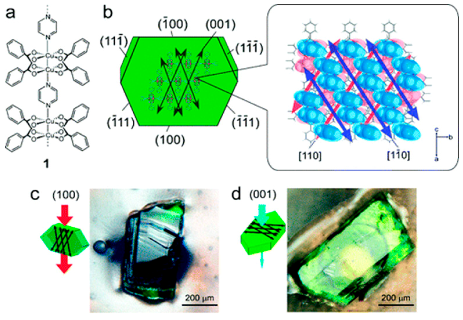
  135. Takamizawa, S.; Takasaki, Y.; Miyake, R. Single-crystal membrane for anisotropic and efficient gas permeation. J. Am. Chem. Soc. 2010, 132, 2862–2863. [Google Scholar] [CrossRef] [PubMed]
  136. Kang, Z.; Xue, M.; Fan, L.; Huang, L.; Guo, L.; Wei, G.; Chen, B.; Qiu, S. Highly selective sieving of small gas molecules by using an ultra-microporous metal-organic framework membrane. Energy Environ. Sci. 2014, 7, 4053–4060. [Google Scholar] [CrossRef]
  137. Fu, J.; Das, S.; Xing, G.; Ben, T.; Valtchev, V.; Qiu, S. Fabrication of COF-MOF composite membranes and their highly selective separation of H2/CO2. J. Am. Chem. Soc. 2016, 138, 7673–7680. [Google Scholar] [CrossRef] [PubMed]
  138. Li, Y.; Lin, L.; Tu, M.; Nian, P.; Howarth, A.J.; Farha, O.K.; Qiu, J.; Zhang, X. Growth of ZnO self-converted 2D nanosheet zeolitic imidazolate framework membranes by an ammonia-assisted strategy. Nano Res. 2018, 11, 1850–1860. [Google Scholar] [CrossRef]
  139. Peng, Y.; Li, Y.; Ban, Y.; Yang, W. Two-dimensional metal–organic framework nanosheets for membrane-based gas separation. Angew. Chem. Int. Ed. 2017, 56, 9757–9761. [Google Scholar] [CrossRef] [PubMed]
  140. Service, R.F. The carbon conundrum. Science 2004, 305, 962–963. [Google Scholar] [CrossRef] [PubMed]
  141. Koros, W.J.; Mahajan, R. Pushing the limits on possibilities for large scale gas separation: Which strategies? J. Memb. Sci. 2000, 175, 181–196. [Google Scholar] [CrossRef]
  142. Lin, H.; Freeman, B.D. Materials selection guidelines for membranes that remove CO2 from gas mixtures. J. Mol. Struct. 2005, 739, 57–74. [Google Scholar] [CrossRef]
  143. D’Alessandro, D.M.; Smit, B.; Long, J.R. Carbon dioxide capture: Prospects for new materials. Angew. Chem. Int. Ed. 2010, 49, 6058–6082. [Google Scholar] [CrossRef] [PubMed]
  144. Lai, Z. Development of ZIF-8 membranes: Opportunities and challenges for commercial applications. Curr. Opin. Chem. Eng. 2018, 20, 78–85. [Google Scholar] [CrossRef]
  145. Bux, H.; Chmelik, C.; Krishna, R.; Caro, J. Ethene/ethane separation by the mof membrane ZIF-8: Molecular correlation of permeation, adsorption, diffusion. J. Memb. Sci. 2011, 369, 284–289. [Google Scholar] [CrossRef]
  146. Zou, X.; Zhang, F.; Thomas, S.; Zhu, G.; Valtchev, V.; Mintova, S. Co3(HCOO)6 microporous metal-organic framework membrane for separation of CO2/CH4 mixtures. Chemistry 2011, 17, 12076–12083. [Google Scholar] [CrossRef] [PubMed]
  147. Liu, Y.; Zeng, G.; Pan, Y.; Lai, Z. Synthesis of highly c-oriented ZIF-69 membranes by secondary growth and their gas permeation properties. J. Memb. Sci. 2011, 379, 46–51. [Google Scholar] [CrossRef]
  148. Betard, A.; Bux, H.; Henke, S.; Zacher, D.; Caro, J.; Fischer, R.A. Fabrication of a CO2-selective membrane by stepwise liquid-phase deposition of an alkylether functionalized pillared-layered metal-organic framework [Cu2L2P]n on a macroporous support. Microporous Mesoporous Mater. 2012, 150, 76–82. [Google Scholar] [CrossRef]
  149. Bohrman, J.A.; Carreon, M.A. Synthesis and CO2/CH4 separation performance of BIO-MOF-1 membranes. Chem. Commun. 2012, 48, 5130–5132. [Google Scholar] [CrossRef] [PubMed]
  150. Xie, Z.; Li, T.; Rosi, N.L.; Carreon, M.A. Alumina-supported cobalt–adeninate MOF membranes for CO2/CH4 separation. J. Mater. Chem. A 2014, 2, 1239–1241. [Google Scholar] [CrossRef]
  151. Zhao, Z.; Ma, X.; Kasik, A.; Li, Z.; Lin, Y.S. Gas separation properties of metal organic framework (MOF-5) membranes. Ind. Eng. Chem. Res. 2013, 52, 1102–1108. [Google Scholar] [CrossRef]
  152. Rui, Z.; James, J.B.; Lin, Y.S. Highly CO2 perm-selective metal-organic framework membranes through CO2 annealing post-treatment. J. Membr. Sci. 2018, 555, 97–104. [Google Scholar] [CrossRef]
  153. Al-Maythalony, B.A.; Shekhah, O.; Swaidan, R.; Belmabkhout, Y.; Pinnau, I.; Eddaoudi, M. Quest for anionic MOF membranes: Continuous sod-ZMOF membrane with CO2 adsorption-driven selectivity. J. Am. Chem. Soc. 2015, 137, 1754–1757. [Google Scholar] [CrossRef] [PubMed]
  154. Bernardo, P.; Drioli, E.; Golemme, G. Membrane gas separation: A review/state of the art. Ind. Eng. Chem. Res. 2009, 48, 4638–4663. [Google Scholar] [CrossRef]
  155. Xue, D.X.; Cadiau, A.; Weselinski, L.J.; Jiang, H.; Bhatt, P.M.; Shkurenko, A.; Wojtas, L.; Zhijie, C.; Belmabkhout, Y.; Adil, K.; et al. Topology meets MOF chemistry for pore-aperture fine tuning: ftw-MOF platform for energy-efficient separations via adsorption kinetics or molecular sieving. Chem. Commun. 2018, 54, 6404–6407. [Google Scholar] [CrossRef] [PubMed]
  156. Eldridge, R.B. Olefin/paraffin separation technology: A review. Ind. Eng. Chem. Res. 1993, 32, 2208–2212. [Google Scholar] [CrossRef]
  157. Li, K.; Olson, D.H.; Seidel, J.; Emge, T.J.; Gong, H.; Zeng, H.; Li, J. Zeolitic imidazolate frameworks for kinetic separation of propane and propene. J. Am. Chem. Soc. 2009, 131, 10368–10369. [Google Scholar] [CrossRef] [PubMed]
  158. Dechnik, J.; Gascon, J.; Doonan, C.J.; Janiak, C.; Sumby, C.J. Mixed-matrix membranes. Angew. Chem. Int. Ed. 2017, 56, 9292–9310. [Google Scholar] [CrossRef] [PubMed]
  159. Buonomenna, M.G.; Yave, W.; Golemme, G. Some approaches for high performance polymer based membranes for gas separation: Block copolymers, carbon molecular sieves and mixed matrix membranes. RSC Adv. 2012, 2, 10745–10773. [Google Scholar] [CrossRef]
  160. Li, J.R.; Sculley, J.; Zhou, H.C. Metal-organic frameworks for separations. Chem. Rev. 2012, 112, 869–932. [Google Scholar] [CrossRef] [PubMed]
  161. James, J.B.; Wang, J.; Meng, L.; Lin, Y.S. ZIF-8 membrane ethylene/ethane transport characteristics in single and binary gas mixtures. Ind. Eng. Chem. Res. 2017, 56, 7567–7575. [Google Scholar] [CrossRef]
  162. Shah, M.N.; Gonzalez, M.A.; McCarthy, M.C.; Jeong, H.K. An unconventional rapid synthesis of high performance metal-organic framework membranes. Langmuir 2013, 29, 7896–7902. [Google Scholar] [CrossRef] [PubMed]
  163. Hara, N.; Yoshimune, M.; Negishi, H.; Haraya, K.; Hara, S.; Yamaguchi, T. Diffusive separation of propylene/propane with ZIF-8 membranes. J. Memb. Sci. 2014, 450, 215–223. [Google Scholar] [CrossRef]
  164. Liu, D.; Ma, X.; Xi, H.; Lin, Y.S. Gas transport properties and propylene/propane separation characteristics of ZIF-8 membranes. J. Memb. Sci. 2014, 451, 85–93. [Google Scholar] [CrossRef]
  165. Eum, K.; Ma, C.; Rownaghi, A.; Jones, C.W.; Nair, S. ZIF-8 membranes via interfacial microfluidic processing in polymeric hollow fibers: Efficient propylene separation at elevated pressures. ACS Appl. Mater. Interfaces 2016, 8, 25337–25342. [Google Scholar] [CrossRef] [PubMed]
  166. Eum, K.; Ma, C.; Koh, D.-Y.; Rashidi, F.; Li, Z.; Jones, C.W.; Lively, R.P.; Nair, S. Zeolitic imidazolate framework membranes supported on macroporous carbon hollow fibers by fluidic processing techniques. Adv. Mater. Interfaces 2017, 4, 1700080–1700090. [Google Scholar] [CrossRef]
  167. Belmabkhout, Y.; Pillai, R.S.; Alezi, D.; Shekhah, O.; Bhatt, P.M.; Chen, Z.; Adil, K.; Vaesen, S.; De Weireld, G.; Pang, M.; et al. Metal-organic frameworks to satisfy gas upgrading demands: Fine-tuning the soc-mof platform for the operative removal of H2S. J. Mater. Chem. A 2017, 5, 3293–3303. [Google Scholar] [CrossRef]
  168. Suleman, M.S.; Lau, K.K.; Yeong, Y.F. Plasticization and swelling in polymeric membranes in CO2 removal from natural gas. Chem. Eng. Technol. 2016, 39, 1604–1616. [Google Scholar] [CrossRef]
  169. Robeson, L.M. The upper bound revisited. J. Membr. Sci. 2008, 320, 390–400. [Google Scholar] [CrossRef]
Figure 1. Landscape for metal–organic framework (MOF) research areas, from discovery and design to applications.
Crystals 08 00412 g001
Figure 2. Schematic representation of the MOF membrane preparation methods, like solvothermal growth method and seeding (a,b), counter diffusion (c), gel-vapor deposition (d), and layer-by-layer (e).
Crystals 08 00412 g002
Figure 3. SEM images of the MOF-5 membrane: (a) top view; and, (b) cross-section (adapted with permission from ref. [56]).
Crystals 08 00412 g003
Figure 4. Top view SEM pictures of Ni2(L-asp)2(bipy) membranes grown for (a) 1 h, (b) 2 h, (c) 3 h, and (d) 4 h at 150 °C (adapted with permission from ref. [79]).
Crystals 08 00412 g004
Figure 5. Schematic illustration of the preparation of a pure ZIF-67 membrane by the self-conversion of carbonate hydroxide nanowire arrays (Co-NWAs) (adapted with permission from ref. [81]).
Crystals 08 00412 g005
Figure 6. Scheme for preparing ZIF-90 membranes using 3-aminopropyltriethoxysilane (APTES) as a covalent linker between a ZIF-90 membrane and an Al2O3 support via an imine condensation reaction (adapted with permission from ref. [82]).
Crystals 08 00412 g006
Figure 7. Scheme of the preparation of bicontinuous ZIF-8@GOmembranes through the layer-by-layer deposition of graphene oxide on the semicontinuous ZIF-8 layer, which was synthesized on a polydopamine-modified alumina disk (adapted with permission from ref. [86]).
Crystals 08 00412 g007
Figure 8. SEM images at different stages of MOF membrane growth: (a) α-alumina support, (b) seed layer, (c) membrane (top view), and (d) membrane (cross-section view) (adapted with permission from ref. [90]).
Crystals 08 00412 g008
Figure 9. Schematic diagram of preparing the MIL-53 membrane on an alumina support via the reactive seeding method (adapted with permission from ref. [91]).
Crystals 08 00412 g009
Figure 10. Schematic illustration of membrane synthesis using the counter-diffusion-based in situ method (adapted with permission from ref. [69]).
Crystals 08 00412 g010
Figure 11. Structure of poly-thiosemicarbazide (adapted with permission from ref. [95]).
Crystals 08 00412 g011
Figure 12. SEM surface images of ZIF-8/PTSC membranes prepared with different reactant concentrations: (a) M1, (b) M2, (c) M3, and (d) M4. Scale bar: 10 mm (adapted with permission from ref. [95]).
Crystals 08 00412 g012
Figure 13. Gel–vapor deposition (GVD) fabrication of ultrathin ZIF-8 membrane. (a) Schematic of MOF membrane formation process. (b) Schematic illustration and chemical structure of Zn-based gel and crystalline structure of ZIF-8. Zn, O, C and N atoms are depicted in yellow, red, grey, and blue, respectively. H atoms are not presented for clarity. Top view SEM images of (c) the PVDF hollow fiber and (d) the Zn-based gel layer. SEM images of (e) top and (f) cross-sectional view of the ZIF-8 membrane prepared with sol concentration of 1 U and coating time of 2 s. The images are colored for clarity. Scale bar, 200 nm (adapted with permission from ref. [92]).
Crystals 08 00412 g013
Figure 14. Schematic representation of the vapor-assisted conversion process for the fabrication of oriented MOF films (adapted with permission from ref [97].
Crystals 08 00412 g014
Figure 15. Schematic diagram for the automated layer-by-layer (LBL) growth of MOFs thin films on substrates functionalized with self-assembled monolayers (SAMs). The preparation is done by repeated immersion cycles first in a solution of the metal precursor and subsequently in the organic ligand solution, with solvent rinsing in-between (adapted with permission from ref. [53]).
Crystals 08 00412 g015
Figure 16. Representative examples of SEM micrographs of the top view (left) and cross-section (right) of the ZIF-8 membrane grown using 300 cycles of the LPE method on an alumina substrate (adapted with permission from ref. [52]).
Crystals 08 00412 g016
Figure 17. Schematic Representation of the Setup employed for the Fabrication of MOF Thin Films Using the LPE Approach Adapted to the Spin Coating Method (adapted with permission from ref. [54]).
Crystals 08 00412 g017
Figure 18. (a) Top view and (b) cross-section SEM image of ZIF-8 membrane grown on alumina support using the spin coating approach (adapted with permission from ref. [54]).
Crystals 08 00412 g018
Figure 19. H2 permeance and separation factors in the volume ratio binary gas mixture H2–CO2, H2–N2, and H2–CH4 systems of HKUST-1 membrane as a function of time at 40 °C with a pressure drop of 1 atm (adapted with permission from ref. [114]).
Crystals 08 00412 g019
Figure 20. Scheme of the preparation of ZIF-8 membranes on hydrophobic α-Al2O3 supports through 1H,1H,2H,2H-perfluoroalkyltriethoxysilanes (POTS) modification (adapted with permission from ref. [121]).
Crystals 08 00412 g020
Figure 21. (a) The permeation properties of various gases through the ZIF-8/rGO membrane. (b) The separation performance of the ZIF-8/rGO membrane for H2/CO2, H2/N2, and H2/CH4 mixtures. The comparison of the GO, rGO, and ZIF-8/rGO membranes for (c) H2/N2 and (d) H2/CH4 separations. (adapted with permission from ref. [122]).
Crystals 08 00412 g021
Figure 22. (a) H2 (solid triangles) and N2 (triangles) permeance from the mixture through the ZIF-7 membrane during the on-stream activation process with increasing temperature. (b) permeance of single gases (circles) and from mixtures (squares: H2–CO2 mixture, rhombuses: H2–N2 mixture, triangles: H2–CH4 mixture) of the ZIF-7 membrane at 200 °C as a function of molecular kinetic diameters (adapted with permission from ref. [123]).
Crystals 08 00412 g022
Figure 23. H2/CO2 selectivity versus H2 permeability for polymeric and MOF membranes (adapted with permission from ref. [125]).
Crystals 08 00412 g023
Figure 24. (a) Single gas permeabilities through the prepared ZIF-67 membrane measured at 30 °C and 0.1 MPa. The inset shows the separation factors of H2 relative to the other gases in both the single gas and equimolar mixed gas permeation tests. (b) Single gas permeances at elevated temperature. (c) Ideal separation factors of H2 over CO2 (gray), N2 (red) and CH4 (black) at different temperatures. (d) H2/CH4 mixture separation as a function of temperature. (adapted with permission from ref. [81]).
Crystals 08 00412 g024
Figure 25. Single gas permeances through the ZIF-100 membrane prepared by PDA-modification at 25 °C and 1 bar as a function of the kinetic diameter of permeated gases. The inset shows the mixture separation factors for H2 over other gases from equimolar mixtures. (adapted with permission from ref. [126]).
Crystals 08 00412 g025
Figure 26. (a) Schematically measuring principle to clarify the permeation data in both directions of the neat, supported ZIF-67, ZIF-67-on-ZIF-8, and ZIF-67-on-ZIF-8 layers (b) Permeation data for H2/CO2, (c) for H2/CH4, (d) for H2/N2, (e) for H2/ethane, (f) for H2/ethylene, (g) for H2/propane, and (h) for H2/propylene. All membranes show clearly a separation factor α above Knudsen (purple, dotted line). The orange dashed line shows the performance of conventionally prepared neat ZIF-8 membrane taken from comparable literature data. (adapted with permission from ref. [127]).
Crystals 08 00412 g026
Figure 27. (Left). SEM images of the MIL-53 seed layer (a), MIL-53 powders (b), MIL-53 membrane surface (c), and cross-section (d). (right) Permeances of small gas molecules through an MIL-53 membrane at different trans-membrane pressure drops, and the single-component gas permeation (SCGP) results through the MIL-53 membrane under 0.8 MPa (adapted with permission from ref. [91]).
Crystals 08 00412 g027
Figure 28. (a): plot of H2/CO2 permeance and separation factors for the NH2-MIL-53(Al) membrane versus test time. (b): hydrogen separation power of the NH2-MIL-53(Al) membrane as a function of the permeation temperature (adapted with permission from ref. [128]).
Crystals 08 00412 g028
Figure 29. (a) H2/CO2 mixture separation factor α (columns) and H2 (□) and CO2 (▽) permeances for the two neat supported MIL-96(Al) membranes (left, toluene/water seeding; right, DMF/water seeding) at room temperature. Measurements carried out directly after synthesis (as synth.) and after 24 h activation at 150 °C in a nitrogen flow (act.). (b) Schematic connectivity between the three different cavities (A), (B), and (C), showing that the three-dimensional (3D) pore structure is a virtual 2D pore structure since the gas transport is limited to a “zigzag” pathway (arrows) between the two cavities (B) and (C) (adapted with permission from ref. [129]).
Crystals 08 00412 g029
Figure 30. Mixed (a) and single gas permeabilities (b) for H2 (∇) and CO2 (⎕) and ideal/real separation factors (columns) for an equimolar mixture of H2/CO2 at different temperatures for the neat supported NH2-MIL-125 membrane. (adapted with permission from ref. [130]).
Crystals 08 00412 g030
Figure 31. (ac) SEM images of original CuBTC membrane, transformed CuBTC/MIL-100 membrane and transformed CuBTC/MIL-100 membrane after purification, respectively. Scale bar, 20 μm. (d,e) Gas permeance and selectivities of the CuBTC and CuBTC/MIL-100 membranes. All the average permeation results with standard deviation were calculated from three measurement data. (f) Effect of temperature on H2 permeance and H2/CO2 and H2/N2 selectivities for CuBTC/MIL-100 membrane. (g) Comparison of CuBTC/MIL-100 membrane with polymeric, silica, zeolite, other MOF, and graphene oxide membranes for H2/N2 system. 1 barrer = 3.348 × 10⁻¹⁶ mol m−2 s−1 Pa−1, the red dotted line is the Robeson’s upper-bound reported in 2008. (adapted with permission from ref. [131].).
Crystals 08 00412 g031
Figure 32. H2 and CO2 permeances from equimolar binary mixtures and H2/CO2 mixed gas separation factor of the CAU-10-H membrane as a function of the feed pressure at 200 °C. (adapted with permission from ref. [132]).
Crystals 08 00412 g032
Figure 33. Scheme of the synthesis of Mg-MOF-74 membrane on MgO-seeded Al2O3 supports and amine-modification of the as-prepared Mg-MOF-74 membrane. (adapted with permission from ref. [77]).
Crystals 08 00412 g033
Figure 34. Single gas permeances on the as-prepared and amine-modified Mg-MOF-74 membranes at 25 °C and 1 bar as a function of the kinetic diameter. The inset shows the mixture separation factors for H2 over other gases from equimolar mixtures (for the temperature dependence of the H2/CO2 mixed gas selectivities) (adapted with permission from ref. [77]).
Crystals 08 00412 g034
Figure 35. Mixture separation factors for H2/CO2 from equimolar mixture (left) and single gas permeances of H2 and CO2 (right) on the as-prepared and amine-modified Mg-MOF-74 membranes at 1 bar as a function of temperature. (adapted with permission from ref. [77]).
Crystals 08 00412 g035
Figure 36. (a) Single- (□) and binary- (○) gas permeances of different gases on the Cu(bipy)2(SiF6) membrane at 293 K as a function of the kinetic diameter (inset: the separation factor for H2 over other gases by binary gases tests). (b) Plot of H2–CO2, H2–CH4 and H2–N2 separation factors of the Cu(bipy)2(SiF6) membranes (average values of five different membranes) at different test times. Permeation temperature = 293 K, feed pressure = 1 × 10⁵ Pa (adapted with permission from ref. [134]).
Crystals 08 00412 g036
Figure 37. (a) Chemical structure and (b) crystal structure of [Cu2(bza)4(pyz)]n (1) showing the determined numbers of the crystal planes and the channel direction. (c,d) Photographs of single-crystal membranes of 1: (c) exposed (100) crystal surface (channel membrane); and, (d) (001) crystal surface (nonchannel membrane) (adapted with permission from ref. [135]).
Crystals 08 00412 g037
Figure 38. (a) Comparison of the permeabilities of crystal membrane 1 for various gases: (red) along the channels (channel membrane); (light-blue) perpendicular to the channels (nonchannel membrane). The inset plot (○) is the calculated permeability based on the Knudsen model. (b) Comparison of the permeation fluxes of H2 and CO2 along the channels of gas mixtures for various mixing ratios (H2, purple; CO2, green) (adapted with permission from ref. [135]).
Crystals 08 00412 g038
Figure 39. (a) Schematic diagram of the preparation of Ni2(L-asp)2P (P = bipy or pz) membranes on nickel screens. (b) Schematic description of compound 1 and JUC-150 structure. Ni cyan, C gray, N blue, and O red; the H atoms are omitted for clarity (adapted with permission from ref. [136]).
Crystals 08 00412 g039
Figure 40. (a) The permeances of single gases through the 1 membrane at 298 K as a function of the molecular weight. (b) The permeances of single gases through the JUC-150 membrane at 298 K as a function of the kinetic diameters. (adapted with permission from ref. [136]).
Crystals 08 00412 g040
Figure 41. H2/CH4, H2/N2, and H2/CO2 separation factors of the 1 membrane (solid) and the JUC-150 membrane (hollow) over time (adapted with permission from ref. [136]).
Crystals 08 00412 g041
Figure 42. Schematic representation of the fabrication of covalent-organic frameworks-metal–organic framework (COF-MOF) composite membranes. (adapted with permission from ref. [137]).
Crystals 08 00412 g042
Figure 43. COF-300 membrane: (A) SEM top view, (B) elemental mapping image (carbon), (C) SEM cross-sectional view, and (D) elemental mapping image (silicon). Zn2(bdc)2(dabco) membrane: (E) SEM top view, (F) elemental mapping image (zinc), (G) SEM cross-sectional view, and (H) elemental mapping image (silicon). ZIF-8 membrane: (I) SEM top view, (J) elemental mapping image (zinc), (K) SEM cross-sectional view, and (L) elemental mapping image (silicon). [COF-300]-[Zn2(bdc)2(dabco)] composite membrane: (M) elemental mapping image (zinc), (N) SEM cross-sectional view, (O) elemental mapping image (silicon), and (P) photo image. [COF-300]-[ZIF-8] composite membrane: (Q) elemental mapping image (zinc), (R) SEM cross-sectional view, (S) elemental mapping image (silicon), and (T) photo image. (adapted with permission from ref. [137]).
Crystals 08 00412 g043
Figure 44. (left) Single gas permeability of various gases through the COF-300 membrane, Zn2(bdc)2(dabco) membrane, and [COF-300]-[Zn2(bdc)2(dabco)] composite membrane at room temperature and 1 bar as a function of their kinetic diameters. (right) Single gas permeability of various gases through the COF-300 membrane, ZIF-8 membrane, and [COF-300]-[ZIF-8] composite membrane at room temperature and 1 bar as a function of their kinetic diameters. (adapted with permission from ref. [137]).
Crystals 08 00412 g044
Figure 45. Scheme depicting the preparation procedure of highly oriented Zn2(bIm)4 nanosheet membranes by ZnO self-conversion growth in a GO confined space (adapted with permission from ref. [122]).
Crystals 08 00412 g045
Figure 46. (a) Single gas permeances of the M-9 membrane (inset: ideal separation factors for single gases and separation selectivities for binary gas mixtures for H2 over CO2, N2, and CH4); (b) permeances of binary gas mixtures as a function of temperature difference; (c) long-term operating stability of the M-9 membrane for the separation of an equimolar H2/CO2 mixture in the range of temperatures from 30 to 150 °C at 0.1 MPa; and, (d) comparison of our M-9 membrane with the reported molecular sieve membranes for the separation of H2/CO2 mixtures. The black solid line represents the 2008 upper bound of polymeric membranes for H2/CO2. The black dashed line represents the 2010 upper bound of microporous inorganic membranes for the separation of H2/CO2 mixtures. (adapted with permission from ref. [122]).
Crystals 08 00412 g046
Figure 47. (a) Optical image of a CO3(HCOO)6 membrane grown on a glass frit. (b) Top and (c) side view SEM images of the intergrown layer (adapted with permission from ref. [146]).
Crystals 08 00412 g047
Figure 48. (a) CO2/CH4 permeance and separation factor (SF) of the Co3(HCOO)6 membrane versus permeation temperature. (b) Plot of the CO2/CH4 separation factor of the Co3(HCOO)6 membrane as a function of test time (adapted with permission from ref. [146]).
Crystals 08 00412 g048
Figure 49. (a) Top view of ZIF-69 membrane by secondary growth. (b) Cross section view of ZIF-69 membrane by secondary growth. (c) XRD patterns for (i) ZIF-69 seeded α-alumina substrate, (ii) ZIF-69 powder by simulation from Mercury Software (Cambridge Crystallographic Data Centre), (iii) Highly oriented ZIF-69 membrane by secondary growth in this study. * are peaks from α-alumina substrate (adapted with permission from ref. [147]).
Crystals 08 00412 g049
Figure 50. (a) Single gas permeances of CO2, N2, CH4, and CO through a ZIF-69 membrane as a function of transmembrane pressure drop at 298 K. (b) The ideal selectivities of CO2/CO, CO2/CH4, and CO2/N2 for a ZIF-69 membrane as a function of transmembrane pressure drop at 298 K (adapted with permission from ref. [147]).
Crystals 08 00412 g050
Figure 51. Separation factors for the CO2–CO, CO2–CH4, and CO2–N2 gas mixtures (50% molar each) as a function of test time for the ZIF-69 membrane at 298 K (adapted with permission from ref. [147]).
Crystals 08 00412 g051
Figure 52. (Left) permeance of pure and equimolar mixed CO2 and CH4 measured for the [Cu2(ndc)2(dabco)]n (1) membrane at room temperature (T = 298 K) as a function of pressures at the feed side (total pressures for pure gases, partial pressures for the gas mixture). The ideal and mixed gas separation factors αi and αr were calculated from the corresponding ratio of the CO2/CH4 permeance. (Right) permeance of pure and equimolar mixed CO2 and CH4 measured for the [Cu2(BME-bdc)2(dabco)]n (2) membrane at room temperature (T = 298 K) as a function of pressures at the feed side (total pressures for pure gases, partial pressures for the gas mixture). The ideal and mixed gas separation factors αi and αr were calculated from the corresponding ratio of the CO2/CH4 permeance (adapted with permission from ref. [148].
Crystals 08 00412 g052
Figure 53. Robeson plot for CO2/CH4 mixtures. For comparison, data point for a Bio-MOF-1 membrane is shown (adapted with permission from ref. [149]).
Crystals 08 00412 g053
Figure 54. Revisited Robeson plot for CO2/CH4 mixtures. The separation performance for I and II membranes is included in the plot (adapted with permission from ref. [150]).
Crystals 08 00412 g054
Figure 55. (a) Schematic illustration for the rapid microwave-assisted in situ synthesis of mixed linker ZIF-7-8 membranes and (b) comparison of effective pore aperture of ZIF-8, ZIF-7, and mixed linker ZIF-7-8. de = effective aperture size. (adapted with permission from ref. [66]).
Crystals 08 00412 g055
Figure 56. Binary testing of (a) H2/CH4 and (b) CO2/CH4 for ZIF-7-8 membranes with varying bIm incorporation (adapted with permission from ref. [66]).
Crystals 08 00412 g056
Figure 57. Comparison of (a) H2/CH4 and (b) CO2/CH4 separation performance for mixed-ligand ZIF-7-8 membranes with the parent ZIF membranes (ZIF-7 and ZIF-8). 1 Barrer = 3.348 × 10⁻¹⁶ mol m m–2 s–1 Pa–1 (adapted with permission from ref. [66]).
Crystals 08 00412 g057
Figure 58. Performance comparison of MOF-5 and PMOF-5 membranes for CO2/H2 gas mixture separation at 298 K and a feed pressure of 5 atm: (a) permeance and (b) separation factor (adapted with permission from ref. [151]).
Crystals 08 00412 g058
Figure 59. (Left) SEM images of sod-ZMOF-1 membrane supported on alumina substrate, top view (A), and cross-section (B). (Right) Single gas permeability vs. Lennard-Jones diameter of relevant gases (at 308 K) on sod-ZMOF-1 membranes (adapted with permission from ref. [153]).
Crystals 08 00412 g059
Figure 60. (a) Diffusion coefficients (D) vs. Lennard-Jones diameter. (b) Solubility coefficients (S) (from sorption data) vs. normal boiling point as determined from CV/VP permeation technique at 2 bar (adapted with permission from ref. [153]).
Crystals 08 00412 g060
Figure 61. Cross-section of the supported ZIF-8 membrane (adapted with permission from ref. [145]).
Crystals 08 00412 g061
Figure 62. Permeances and separation factors at T = 298 K of the ZIF-8 membrane as shown in Figure 1 for ethene and ethane as pure component as well as in equimolar mixture for different feed pressures. The mixture measurements were carried out using the Wicke–Kallenbach technique (partial pressure of the C2 component ≈ 0 at the permeate side) while for the single gas measurement no sweep gas was used (partial pressure of the C2 component ≈ 1 bar at the permeate side). For gas mixtures, the permeances were calculated at T = 293.15 K and p = 1.013 bar from the applied partial pressure difference (for equimolar composition this is 1/2 feed pressure) and for pure component from the total pressure difference (p = 5 bar) (adapted with permission from ref. [145]).
Crystals 08 00412 g062
Figure 63. Propylene/propane separation performance of ZIF-8 membranes as a function of growth time at room temperature. ZIF-8 membranes show excellent propylene/propane separation factors (~50) even after growing for 30 min (adapted with permission from ref. [69]).
Crystals 08 00412 g063
Figure 64. Comparison of the propylene/propane separation performance of our ZIF-8 membranes with those of other membranes reported in the literature. Half- and full-filled symbols indicate separation data from single and binary gas permeation measurements, respectively. The shaded area in the graph implies the performance requirement of a membrane (a minimum permeability of 1 bar and a selectivity of 35) for commercial application. The solid lines are the so-called Robson upper bound, the triangle is the carbon membrane, the circle is a zeolite membrane, the rectangle is a polymer membrane, the pentagon is a ZIF-8 membrane, the hexagon is a ZIF-8 mixed matrix membrane, and the star is the ZIF-8 membrane in this work (adapted with permission from ref. [69]).
Crystals 08 00412 g064
Figure 65. Off-stream stability and on stream stability test of C3H6–C3H8 mixture gas permeances on the ZIF-8 membrane at 35 °C (adapted with permission from ref. [164]).
Crystals 08 00412 g065
Figure 66. Cross-sectional SEM images of (a) Case 2 ZIF-8 hollow fiber membrane showing crystal overgrowths inside the fiber bore; (b,c) Case 3 ZIF-8/hollow fiber membrane; and, (d) XRD patterns of bare PAI membrane and Case 3 ZIF-8 membrane, with a simulated XRD pattern of ZIF-8 shown for comparison (adapted with permission from ref. [165]).
Crystals 08 00412 g066
Figure 67. Permeance and separation factor of a ZIF-8 hollow fiber membrane operated continuously for 30 days under an equimolar C3H6/C3H8 mixture feed at 25 °C and 1 bar feed pressure (adapted with permission from ref. [165]).
Crystals 08 00412 g067
Figure 68. Permeability and selectivity for a 75/25 CH4/n-C4H10 mixture over time, measured using the time-lag method on ZIF-8 membrane at 308 K (adapted with permission from ref. [53]).
Crystals 08 00412 g068
Figure 69. (Left) Fe-soc-MOF-1b membrane grown on alumina support and its PXRD pattern compared to the bulk material. (Right) Top-view (ac,d) cross-sectional SEM images of the Fe-soc-MOF membrane grown on the alumina support (adapted with permission from ref. [167]).
Crystals 08 00412 g069
Figure 70. Permeation properties of Fe-soc-MOF-1b as a function of the kinetic diameters of H2, O2, N2, CH4, CO2 (left) and CH4, CO2, C2H4, C2H6, C3H6, C3H8, and n-C4H10 (right) (adapted with permission from ref. [167]).
Crystals 08 00412 g070
Figure 71. Comparison of permeation properties of MOFs to the performance of polymeric materials reported in the literature for membrane-based: (a) diffusion-driven H2/CO2 separation (b) sorption-driven reverse selective CO2/H2 separation. All the data points are listed in the supporting information (Tables S1 and S2).
Crystals 08 00412 g071
Figure 72. Comparison of permeation properties of MOFs to the performance of polymeric materials reported in the literature for membrane-based: (a) CO2/CH4 separation (b) CO2/N2 separation. All the data points are listed in the supporting information (Tables S3 and S4).
Crystals 08 00412 g072
Figure 73. Comparison of permeation properties of MOFs to the performance of polymeric materials reported in the literature for membrane-based: (a) C2H4/C2H6 separation (b) C3H6/C3H8 separation, (c) C4H10/i-C4H10 separation. All the data points are listed in the supporting information (Tables S5–S7).
Crystals 08 00412 g073

