1. Introduction
Aero-engine components operate under severe thermal, mechanical, and oxidative environments, and their reliability is closely associated with the overall performance of aircraft propulsion systems [
1]. Among the materials used for hot-section components, nickel-based superalloys such as Inconel 625 (IN625) have attracted extensive attention because of their high-temperature strength, oxidation resistance, fatigue resistance, and creep resistance [
2,
3,
4]. However, long-term exposure to complex service conditions may still cause surface degradation, wear, cracking, or local failure of aero-engine blades [
5]. Therefore, efficient surface repair and strengthening technologies are required to extend component lifetime. Laser cladding is a promising remanufacturing method in which a high-energy laser beam melts the feedstock material and a thin layer of the substrate, forming a dense coating with metallurgical bonding. Owing to its rapid solidification, relatively low dilution, narrow heat-affected zone, and controllable microstructure, this technique has been widely considered suitable for the repair and performance enhancement of aero-engine components [
6,
7,
8].
To further improve the service performance of IN625-based cladding layers, ceramic reinforcements have been incorporated into the alloy matrix. Typical reinforcing phases include TiC, WC, B
4C, NbC, SiC, and other hard ceramic particles. Chen et al. prepared TiC/IN625 coatings by extreme high-speed laser cladding and reported that TiC addition refined the dendritic structure and improved resistance to high-temperature hot corrosion [
9,
10]. Zhang et al. found that nano-TiC addition could inhibit Laves phase formation and enhance the tensile properties of IN625 fabricated by laser directed energy deposition [
11]. Dejene et al. further fabricated TiC/IN625 composite coatings using buffer-layer-assisted multilayer directed energy deposition, which significantly increased the coating microhardness and reduced the friction coefficient by suppressing Fe dilution and improving TiC distribution [
12]. Li et al. investigated WC-reinforced IN625 coatings and showed that WC particles increased coating hardness, although irregular WC morphology could intensify wear damage under sliding conditions [
13]. B
4C nanoparticles may react during cladding to form borides and carbides, but excessive B
4C addition can increase cracking susceptibility [
14]. In addition, VC-reinforced coatings show a non-monotonic relationship between microhardness and erosion resistance [
15]. NbC and SiC are also attractive reinforcements for IN625 coatings. NbC can contribute to grain refinement and high-temperature oxidation resistance, partly because Nb-containing oxides such as Nb
2O
5 may form during oxidation [
16]. SiC may decompose or react in the molten pool, providing C and Si for carbide formation and promoting microstructural refinement, thereby improving wear resistance [
17].
Although individual ceramic reinforcements can improve specific properties of IN625 coatings, it is difficult for a single phase to simultaneously optimize microhardness, toughness, corrosion resistance, and wear resistance. For this reason, multi-phase strengthening has become an important strategy for designing high-performance Ni-based composite coatings. One route is to generate multiple hard phases through in situ reactions during laser processing. For example, ZrB
2/IN625 composite coatings exhibited improved microhardness and wear resistance after optimization of line energy and powder feeding density [
18]. Ti
3SiC
2 addition can produce in situ carbides such as (Nb, Ti)C and MC phases while suppressing Laves phase formation, leading to enhanced high-temperature tensile properties [
19]. In addition to hard ceramic reinforcement, the incorporation of solid-lubricating phases provides another effective strategy for improving the tribological performance of IN625 coatings under severe service conditions. For instance, Ag/MoS
2-modified IN625 self-lubricating coatings have been reported to maintain a low and stable friction coefficient over a wide temperature range under vacuum, owing to the formation of Ag- and sulfide-rich lubricious tribofilms during sliding [
20]. These studies suggest that a properly designed multi-reinforcement system may provide a more balanced strengthening effect than a single ceramic phase.
Direct addition of multiple reinforcing phases is another effective approach. In IN625-based coatings, Nb-related phases and SiC can play complementary roles during laser cladding. Appropriate Nb addition has been reported to promote NbC formation, induce lattice distortion and solid-solution strengthening, and improve corrosion resistance through a plugging effect [
21], which arises from Nb-containing phase oxidation products (e.g., NbO
2) filling surface defects, not from NbC itself. Wang et al. [
17] further demonstrated that SiC can decompose into C and Si in the molten pool, followed by reactions with Nb, Mo, Cr, and other elements to form hard carbides such as M(Nb,Mo)C and Cr
23C
6. In addition, partially retained SiC particles can act as heterogeneous nucleation sites, contributing to grain refinement. Their results showed that the introduction of Nb and SiC refined grains, increased microhardness, and reduced wear rate, indicating a potential synergistic strengthening effect between Nb-containing carbides and SiC-derived reaction products.
However, previous studies have mainly focused on single ceramic reinforcements, relatively high Nb contents, variable SiC additions, or systems in which composition and processing parameters were changed simultaneously. Therefore, the laser-power-dependent behavior of low-content NbC/SiC-reinforced IN625 coatings remains insufficiently understood. In this work, a fixed composition of IN625-2 wt.% NbC-2 wt.% SiC was selected based on preliminary experiments, in which lower ceramic contents showed limited strengthening, whereas excessive ceramic addition tended to cause particle agglomeration, insufficient melting, and local defects. In the present work, IN625 was used as the substrate, and IN625-2NbC-2SiC composite coatings were fabricated by laser cladding under different laser powers. The phase constitution, microstructure, microhardness, friction coefficient, wear rate, and worn-surface morphology of the coatings were systematically analyzed. The objective of this study is to clarify the effect of laser power on the formation quality and wear resistance of low-content NbC/SiC-reinforced IN625 coatings, and to provide experimental support for the design of cost-effective IN625-based composite coatings with improved tribological performance.
3. Results and Discussion
3.1. Phase Composition
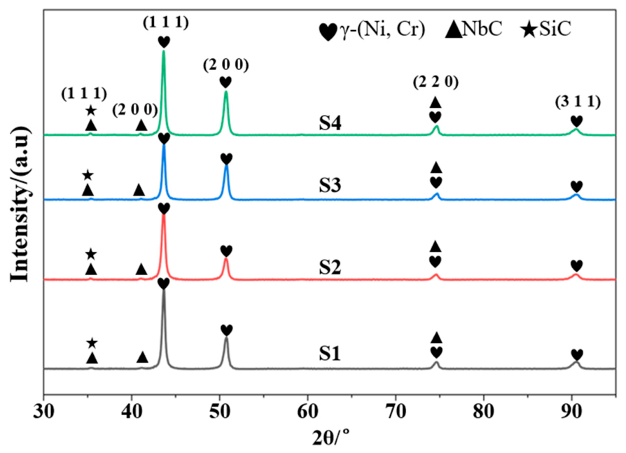
The XRD patterns of the IN625-2NbC-2SiC coatings fabricated at different laser powers are presented in
Figure 2. For all samples, the main diffraction peaks appear near 44°, 51°, 75°, and 91°, which correspond to the (1 1 1), (2 0 0), (2 2 0), and (3 1 1) planes of the γ-(Ni, Cr) phase with a face-centered cubic structure [
18]. This result confirms that the γ matrix remains the primary constituent of the laser cladding coatings. Besides the dominant γ peaks, several weak peaks corresponding to NbC and SiC are detected, implying that part of the ceramic reinforcements survived the laser cladding process. Due to the low contents of NbC and SiC and partial overlap of their diffraction peaks, especially around 35°−36°, accurate distinction and quantitative analysis of these two phases based solely on the XRD results are difficult.
Within the investigated laser-power range of 900−1800 W, no significant changes in the major peak positions or phase composition are detected among the samples, indicating that within the process window of this study, variations in laser power do not induce the formation of any new phases that can be clearly identified by XRD. Some differences in the diffraction peak intensities of the γ-(Ni, Cr) phase are observed among the specimens, which may be related to variations in the degree of melting, grain orientation, and local microstructural uniformity of the cladding layers [
23]. For example, the relatively lower intensity of the γ-(2 0 0) peak in S2 may reflect a change in preferred crystallographic orientation under this laser-power condition. Since crystallographic orientation can influence deformation behavior and hardness through the Schmid factor, quantitative texture analysis would be required to further clarify this effect. However, such analysis requires EBSD characterization and is therefore beyond the scope of the present study. Since XRD provides limited information on local elemental distribution and fine microstructural features, SEM/EDS characterization was further performed to analyze the microstructure, elemental distribution, and possible local enrichment of ceramic-related elements.
3.2. Microstructure
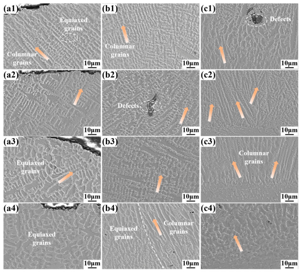
The SEM morphologies of the IN625-2NbC-2SiC coatings obtained at various laser powers are compared in
Figure 3. Overall, each coating exhibits typical rapid solidification characteristics associated with laser cladding, consisting primarily of cellular crystals, columnar dendrites, and localized equiaxed grains. During laser cladding, heat is mainly extracted through the underlying substrate, producing a strong thermal gradient near the bonding region. Under this condition, grains tend to grow epitaxially from the substrate toward the coating interior, resulting in the formation of columnar dendrites. In contrast, the upper region of the coating experiences a lower thermal gradient and a different solidification environment, where localized equiaxed grains are more likely to develop [
24]. Therefore, the microstructural difference along the coating thickness can be attributed to the combined effect of thermal gradient and solidification rate during molten-pool solidification [
25].
With the laser power raised from 900 to 1800 W, the melting state and the coating microstructure show certain variations. At relatively low laser power, the heat input to the melt pool is insufficient, which may lead to incomplete melting of the powder, poor melt pool fluidity, and local microstructural inhomogeneity [
26]. A moderate increase in laser power improved the thermal state and flow behavior of the liquid metal, facilitating particle melting, solute redistribution, and densification of the cladding layer. These changes contributed to better coating integrity and stronger metallurgical bonding with the substrate. However, excessive laser power introduced an overly high thermal input, which could extend the residence time of the molten pool and slow the solidification process. Consequently, grain coarsening may be promoted, and the reaction between ceramic particles and the molten matrix may become more pronounced.
Based on the XRD results, the coatings are dominated by the γ-(Ni, Cr) matrix phase. Therefore, the cellular and dendritic regions identified from the SEM observations can be mainly assigned to the γ substrate. The weak diffraction peaks of NbC and SiC detected by XRD suggest that some of the ceramic reinforcing phases may remain after laser cladding. Meanwhile, because of the high melt pool temperature during laser cladding, partial dissolution or decomposition of some NbC or SiC particles may also occur. In addition, the SEM images show some contrast differences in the interdendritic regions, which may be attributed to local segregation of elements such as Nb, Mo, C, or Si during solidification. Such elemental segregation may further contribute to the precipitation of fine secondary phases.
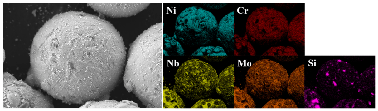
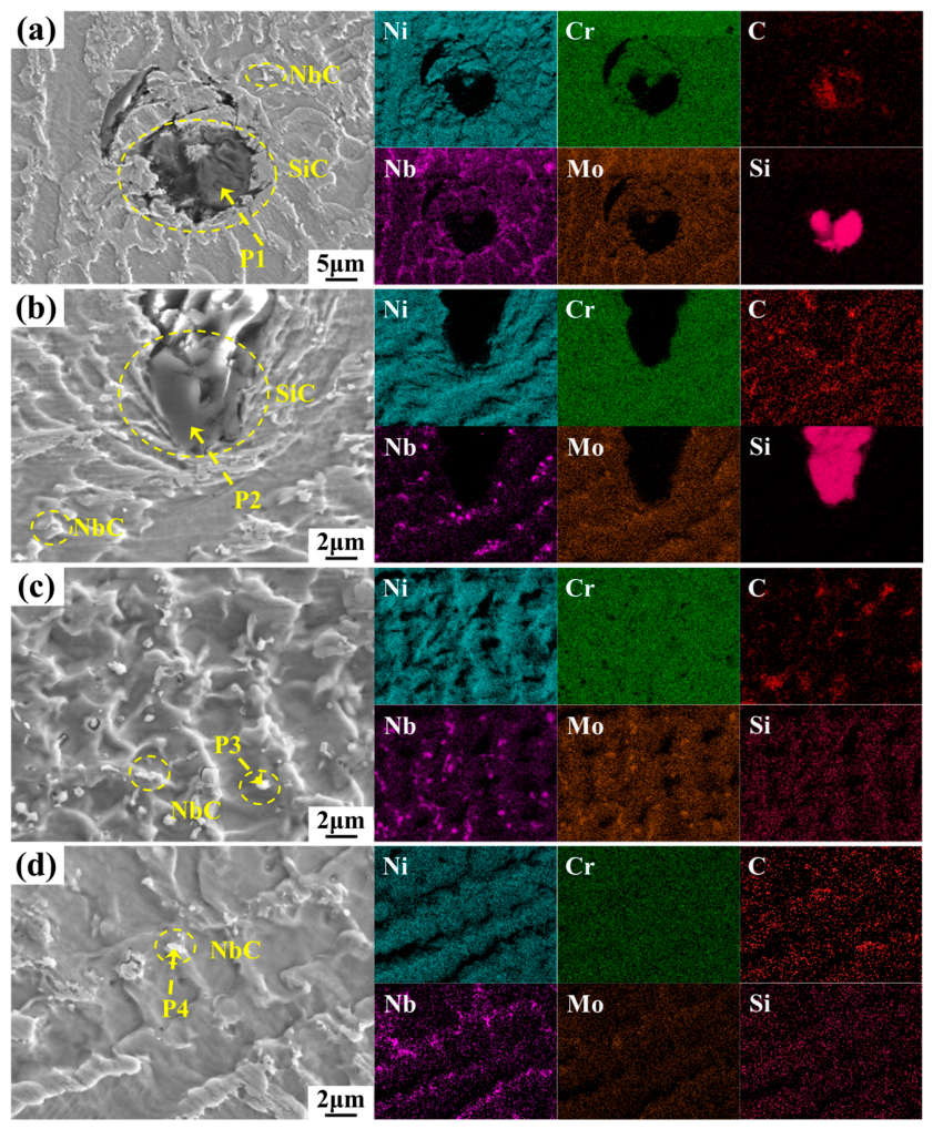
Figure 4 shows the SEM images and EDS elemental mapping results of the IN625-2NbC-2SiC composite coatings prepared under different laser powers. The quantitative EDS mapping results are summarized in
Table 3, and the point-analysis results of selected enriched regions are listed in
Table 4. It should be noted that EDS can only reveal elemental distribution and local enrichment, but cannot independently identify crystalline phases. Therefore, Nb/C-enriched regions are described as possible NbC or Nb-containing carbide regions, together with the XRD results.
For S1, obvious irregular defect regions are observed within the coating. According to
Table 4, P1 and P2 are strongly enriched in C and Si, while the contents of Ni, Cr, and Mo are relatively low. These results indicate that the defects are Si–C-rich regions, which may result from insufficient melting, uneven dispersion, or local accumulation of SiC particles under low laser power. Moreover, the average Si content in
Figure 4a is only 0.34 wt.% (
Table 3), further suggesting that Si is distributed non-uniformly and concentrated in localized regions. Local Nb/C co-enrichment is also observed. Combined with the weak NbC diffraction peaks detected by XRD, these regions may be associated with retained NbC particles or Nb-containing carbides, although EDS alone cannot provide definitive phase identification. At low laser power, insufficient heat input and poor molten-pool fluidity hinder particle redistribution, resulting in uneven ceramic-particle dispersion and local defect formation [
27]. Regarding sample S2, local Si- and C-rich regions are still present, but their size and severity are reduced compared with those in S1. The Si content increases to 3.42 wt.% according to the EDS mapping results in
Table 3, suggesting that increasing the laser power improves powder melting, molten-pool fluidity, and particle dispersion. Meanwhile, Nb and C still exhibit some local co-enrichment, suggesting that some Nb-containing carbides may be present or form during solidification.
Turning to S3, obvious Si–C-rich defect regions are hardly observed, and the EDS maps show a more homogeneous distribution of Ni, Cr, Nb, Mo, C, and Si. The quantitative results further confirm improved elemental uniformity, while P3 is enriched in Nb and C. Combined with the weak NbC peaks detected by XRD, these Nb/C-enriched regions may be related to retained NbC particles or possible Nb-containing carbides. These results indicate that 1500 W provides suitable heat input, promoting powder melting, molten-pool fluidity, and ceramic-particle dispersion, thereby improving microstructural uniformity and strengthening effect. As for S4, the large Si- and C-rich defect regions are no longer obvious, indicating that the higher laser power promotes powder melting, SiC dissolution, and elemental diffusion in the molten pool. In particular, the EDS point analysis of P4 shows strong Nb and C enrichment, while Si is nearly absent, suggesting that this region may correspond to retained or reprecipitated NbC/Nb-rich carbide, which is also consistent with the weak NbC peaks detected by XRD.
3.3. Microhardness
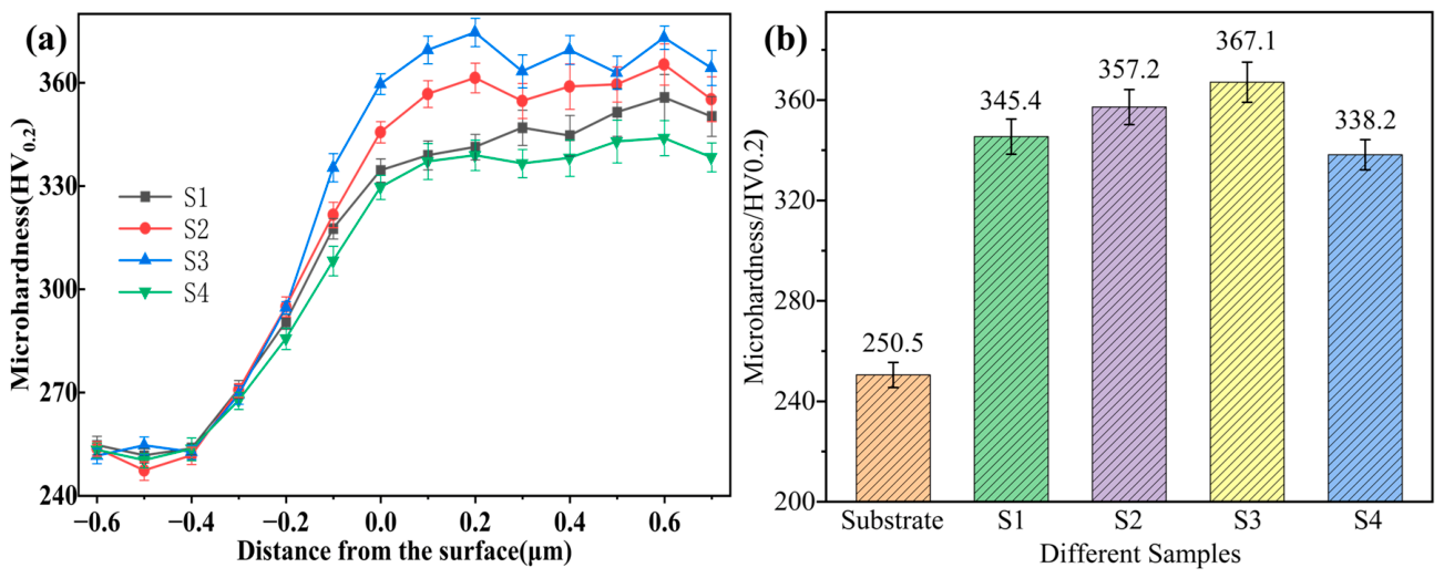
The cross-sectional microhardness distribution of the samples is presented in
Figure 5, along with the corresponding average values. From
Figure 5a, a clear microhardness gradient is observed across the cross-section for all samples. The substrate region has a relatively low and stable microhardness of approximately 250 HV. As the measurement approaches the heat-affected zone (HAZ), a gradual upward trend in microhardness emerges, resulting from localized microstructural evolution driven by the laser-induced thermal cycling. In the fusion zone (FZ), the microhardness increases more rapidly because of the local melting and mixing of the substrate and cladding material, together with the establishment of metallurgical bonding. The coating layer sustains a consistently elevated microhardness level, confirming that the IN625 composite coatings substantially enhance the surface microhardness of the underlying substrate [
28].
Figure 5b provides the average microhardness values, which are 250.5, 345.4, 357.2, 367.1, and 338.2 HV for the substrate, S1, S2, S3, and S4, respectively, following the order S3 > S2 > S1 > S4 > substrate. Since the samples differ only in laser power, the variation in microhardness is mainly associated with the effect of heat input on the molten pool behavior, powder melting, and microstructural homogeneity. At a relatively low laser power, the heat input for S1 is insufficient, resulting in incomplete powder melting and inadequate particle dispersion; therefore, its microhardness is comparatively low [
29]. With rising laser power, the molten pool becomes more fluid, enabling the formation of a denser and more uniform coating with better-dispersed hard constituents. Consequently, the microhardness of S2 and S3 increases gradually. Among all coatings, S3 exhibits the highest average microhardness, indicating that a laser power of 1500 W provides an appropriate heat input and leads to improved microstructural uniformity and strengthening efficiency.
However, further increasing the laser power to 1800 W caused the average microhardness of S4 to decrease to 338.2 HV, indicating that excessive heat input did not further improve the coating microhardness. This reduction should not be simply attributed to local elemental segregation, because segregated solute atoms or fine secondary phases may also act as obstacles to dislocation motion and contribute to local strengthening. In the present study, the lower microhardness of S4 is more likely associated with the combined effects of prolonged molten-pool lifetime, reduced cooling rate, dendrite coarsening [
26], and local microstructural inhomogeneity. According to the Hall–Petch relationship [
30], coarser microstructures provide fewer effective boundaries to impede dislocation motion, thereby weakening the overall strengthening effect. In addition, although local Nb/C- or Si/C-enriched regions may increase microhardness locally, their non-uniform distribution can lead to uneven load-bearing behavior during indentation. Therefore, the decrease in the average microhardness of S4 is mainly attributed to excessive heat-input-induced microstructural coarsening and inhomogeneous reinforcement distribution.
3.4. Tribological Properties
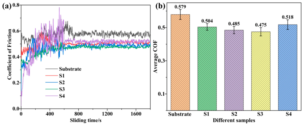
The friction characteristics of the samples are presented in
Figure 6, which displays both the dynamic COF curves and the corresponding average values. As shown in
Figure 6a, the COF of all samples fluctuates markedly during the initial stage, corresponding to the running-in period. With increasing sliding time, the COF gradually reaches a relatively steady state [
31]. The average COF data provided in
Figure 6b are 0.579 for the substrate, 0.504 for S1, 0.485 for S2, 0.475 for S3, and 0.518 for S4. Evidently, every coated sample yields a lower average COF than the uncoated substrate, demonstrating that laser cladding markedly enhances the tribological performance of the substrate surface. The ranking of average COF values is S3 < S2 < S1 < S4 < substrate, suggesting that S3 exhibits the best friction-reducing performance.
Laser power is the only process parameter that varies among the specimens; therefore, the resultant COF differences can be primarily ascribed to the laser-power-dependent coating characteristics, including microstructural refinement, and microhardness level. From S1 to S3, increasing laser power leads to higher microhardness, more stable friction response, and progressively lower COF values. However, the COF of S4 increases to 0.518, which may be attributed to microstructural coarsening or local inhomogeneity caused by excessive heat input. This result is consistent with the microhardness results and worn-surface observations, confirming that S3 has the highest microhardness and the least severe wear damage [
32].
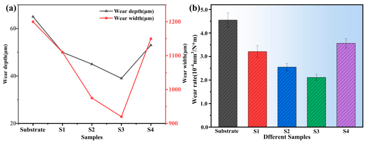
The wear depth, wear width, and wear rate of the uncoated substrate and the laser-cladded specimens are summarized in
Figure 7. It is evident from
Figure 7a that the substrate suffers the greatest wear depth and width, reflecting the most intensive material removal during the sliding process. After laser cladding, all coatings exhibit significantly smaller wear depth and width than the substrate, demonstrating the effectiveness of the IN625-NbC-SiC composite layers in improving wear resistance. With increasing laser power from S1 to S3, the wear depth and width progressively diminish. S3 achieves the smallest values among all samples, indicating the lowest friction-induced material loss. These findings corroborate the microhardness and COF data presented earlier. S3 possesses the highest microhardness and the lowest average COF, enabling it to more effectively resist abrasive cutting and plastic deformation.
Figure 7b reveals that the wear rate follows the same ranking as the other wear parameters. The substrate shows the highest wear rate at about 4.5 × 10
−4 mm
3/(N·m), while S3 achieves the lowest value of roughly 2.1 × 10
−4 mm
3/(N·m). The values for S1, S2, and S4 are intermediate, with S4 showing a higher wear rate than S1−S3. This indicates that an excessively high laser power is not beneficial for further improving wear resistance. Since laser power is the only variable among S1−S4, the differences in wear behavior are mainly related to its influence on coating formation quality, microstructure, and microhardness. A moderate increase in laser power can promote powder melting and molten-pool flow, leading to a more homogeneous coating microstructure and thereby reducing wear rate. Conversely, overly high laser power introduces excessive thermal input that may provoke grain coarsening, or local microstructural inhomogeneity, which weakens the coating’s resistance to abrasive cutting. Consequently, the wear rate of S4 increases instead.
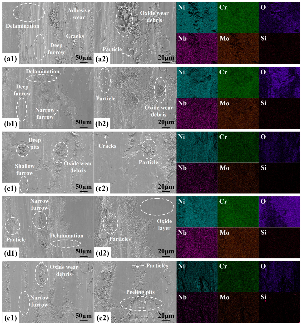
The worn-surface morphologies and corresponding elemental mappings of five samples are presented in
Figure 8. The substrate exhibits pronounced delamination, deep grooves, cracks, and adhesive wear, indicating severe plastic deformation, abrasive plowing, and surface spalling during sliding. Oxidized wear debris and loose particles are also observed on the worn surface; these detached particles may act as third-body abrasives and further accelerate material removal. Thus, the substrate’s wear is primarily attributable to adhesive wear, abrasive wear, and fatigue delamination [
33]. By comparison, S1 demonstrates a relatively smoother worn morphology than the substrate, with adhesive wear being partially restrained. Nevertheless, shallow grooves, pits, cracks, particles, and oxidized debris are still visible, suggesting that its resistance to abrasive cutting remains limited and that local spalling and oxidative wear also occur. For S2, the grooves become narrower and shallower, while the number of pits and cracks decreases. This indicates that a moderate increase in laser power improves the microstructural homogeneity and load-bearing capacity of the coating. Accordingly, the primary wear mechanisms for S2 are identified as mild abrasive wear accompanied by oxidative wear.
S3 exhibits the least severe worn morphology. Its surface topography is relatively smooth, featuring only minor grooves, sparse wear debris, and a comparatively continuous oxide layer. No obvious deep grooves, severe cracks, or large-scale delamination are observed. Combined with the microhardness and friction results discussed above, the higher microhardness and more stable oxide layer of S3 help enhance its resistance to plowing and restrict direct asperity contact with the counterface, thus providing the best overall wear protection. As for S4, deep grooves, delamination, particles, and oxidized wear debris become more evident again, indicating aggravated wear damage. Since the coating composition remains unchanged, the deterioration in the wear performance of S4 is mainly associated with excessive heat input induced by excessively high laser power, which is prone to causing grain coarsening, or local microstructural inhomogeneity, thereby compromising the protective capability of the coating. Based on the worn-surface observations, the wear resistance ranking of the tested samples is established as: S3 > S2 > S1 > S4 > substrate.
4. Conclusions
This study focused on the laser-clad fabrication of IN625-2NbC-2SiC composite coatings and systematically evaluated how varying laser power affects their phase composition, microstructure, microhardness, and wear resistance. The principal conclusions are drawn as follows:
(1) The coatings were mainly composed of γ-(Ni, Cr), NbC, and SiC phases. Laser power had little effect on the main phase constitution, but strongly influenced the coating uniformity. Low laser power caused insufficient melting and local Si/C-rich defects, whereas 1500 W promoted better particle dispersion and elemental homogenization. Excessive laser power led to dendrite coarsening and local microstructural inhomogeneity.
(2) Laser cladding significantly improved the surface microhardness of the IN625 substrate. The average microhardness values of the substrate, S1, S2, S3, and S4 were 250.5, 345.4, 357.2, 367.1, and 338.2 HV, respectively. The S3 coating showed the highest hardness, which was about 46.5% higher than that of the substrate.
(3) All coatings exhibited better wear resistance than the substrate. Among them, S3 showed the lowest coefficient of friction and wear rate, with the wear resistance following the order S3 > S2 > S1 > S4 > substrate. This improvement was mainly attributed to the higher microhardness, more uniform microstructure, and better distribution of reinforcing phases.
(4) Under the present processing conditions, 1500 W, corresponding to an energy density of 31.25 J/mm2, was identified as the optimal laser power. These results indicate that controlling laser energy density is essential for balancing powder melting, ceramic-particle dispersion, and wear performance in low-content NbC/SiC-reinforced IN625 coatings.