Article

Mechanical Degradation and Tempering-Induced Recovery of Nanobainitic Steel After Moderate Sub-Zero Exposure


1
Division of Metallic Systems, Institute of Materials Research, Slovak Academy of Sciences, 04001 Kosice, Slovakia
2
Physics Department, Pryazovskyi State Technical University, 49044 Dnipro, Ukraine
3
Department of Metallic Materials, Technische Universität Berlin, 10623 Berlin, Germany
4
Faculty of Engineering and Physics, National University Zaporizhzhia Polytechnic, 69063 Zaporizhzhia, Ukraine
5
Department of Physical Metallurgy, National Center for Metallurgical Research (CENIM-CSIC), 28040 Madrid, Spain
6
Department SciTec, Ernst-Abbe-Hochschule Jena, University of Applied Sciences, 07745 Jena, Germany
*
Authors to whom correspondence should be addressed.
Crystals 2026, 16(5), 325; https://doi.org/10.3390/cryst16050325
Submission received: 14 April 2026 / Revised: 4 May 2026 / Accepted: 8 May 2026 / Published: 11 May 2026

Abstract

The exploitation of advanced high-strength steels in cold climates requires a deep understanding of their structural stability and mechanical reliability. This study investigates the mechanical response of a 0.45C-1.57Si-2.61Mn (wt.%) steel with nanobainite microstructure to moderate sub-zero exposure (SZE) followed by stress-relief tempering. It was found that SZE at –25 °C and –50 °C induces a progressive degradation of tensile properties and impact toughness that persists after rewarming to room temperature. This deterioration is primarily driven by the accumulation of residual stresses due to thermal expansion mismatch between phases, with only minor contributions from athermal martensitic transformation of retained austenite. Notably, stress-relief tempering at 220 °C effectively restores the tensile performance and doubles the impact toughness compared to the as-austempered condition. Despite Mn and Si segregation which caused a scatter in retained austenite content (13.6–21.5 vol.%), the austenite remains stable throughout the SZE and tempering cycles. These results identify a critical threshold (between 0 °C and –25 °C) for SZE-induced degradation in nanobainitic steels and demonstrate that stress-relief tempering is essential for enhancing their performance in cold-climate applications.

1. Introduction

The development of advanced high-strength steels (AHSSs) has become increasingly important in recent decades [1], particularly for applications in energy, mining, transportation and other sectors, where materials are exposed to extreme loading and harsh environments. Among AHSSs, nanobainitic steels (NBSs) have attracted significant attention due to their unique combination of strength, ductility, and wear resistance [2,3,4]. The nanobainitic microstructure consists of ultra-fine ferrite plates and retained austenite (RA) with both film-like and blocky morphologies, notably lacks the coarse carbides associated with the prior austenite grain boundaries [5,6]. Consequently, bainitic steels demonstrate superior fracture toughness compared to conventional martensitic steels [7,8]. The deformation-induced martensitic transformation (DIMT) of retained austenite further contributes to strain hardening and ductility through the Transformation-Induced Plasticity (TRIP) effect, which delays necking and crack propagation [9,10,11].
NBSs are potentially suitable for challenging engineering tasks, including heavy-loaded components of the technological equipment used in the oil, gas, and mining sectors. Mineral extraction is conducted in various climatic zones, including sub-polar regions where mining and transportation equipment operates under shallow sub-zero temperatures [12,13] reaching –50 °C to –60 °C [14,15]. Cold environments impose severe challenges on structural steels which often suffer from low-temperature embrittlement, reduced fracture toughness, and susceptibility to brittle failure [16,17]. The use of high-strength steels in such climatic zones requires a preliminary investigation of their suitability for low-temperature applications, particularly given the pronounced ductile-to-brittle transition temperature (DBTT) typical of steels with a BCC lattice [18,19].
In previous studies, sub-zero cooling has already been utilized to investigate the microstructure and enhance the mechanical properties of nanobainitic steels, mostly focusing on deep cryogenic temperatures (DCT). Specifically, Argüelles et al. [20] subjected nanostructured bainite (in steels with 0.66–0.98 wt.% C; 1.45–2.90 wt.% Si, and 0.79–1.35 wt.% Mn) to DCT and reported that film-like retained austenite remained stable down to −123 °C, showing no transformation to martensite. Fan et al. [21] and Chen et al. [22] reported that cooling to liquid nitrogen temperature effectively eliminates blocky RA, increases filmy RA stability, and refines the martensitic structure, thereby enhancing the strength characteristics and improving the wear resistance of nanobainitic steel. However, the effect of shallow sub-zero temperatures, typical of cold-climate conditions, on the performance of nanobainitic steels remains largely unexplored.
The microstructural refinement of nanobainitic steels provides a synergy of high tensile strength and enhanced toughness [23,24], making these steels promising candidates for structural applications in cold-climate conditions. It is well known that the mechanical integrity of nanobainitic steels strongly depends on the propensity of retained austenite toward DIMT and the relaxation of stresses generated during this process [25]. A critical processing step to control these behaviors is stress-relief tempering, which has been widely applied to nanobainitic steels to reduce residual stresses, stabilize microstructures, and improve dimensional stability [26,27,28,29,30]. In nanobainitic steels, this treatment can enhance toughness without significantly compromising strength [31,32]. Recent studies emphasize that carefully controlled tempering parameters—specifically temperature and duration—are essential for achieving an optimal strength-toughness balance in the nanobainitic microstructure [33,34,35].
More specifically, Zhao et al. [36] reported that tempering at 300–350 °C improved the yield strength, ductility and impact toughness of pre-ausformed nanobainite in a 0.54C-1.7Si (wt.%) steel while preserving the nanoscale morphology of the microstructure. However, increasing the tempering temperature to 400 °C and above led to a decrease in mechanical properties [36], caused by the coarsening of bainite laths [32] and the decomposition of retained austenite accompanied by transitional carbide precipitation [31]. Previous studies have shown that tempering-induced decomposition of nanobainite can be impeded by ausforming, which introduces new dislocations and stabilizes the sub-structure. As reported by Zorgani et al. [37], following ausforming prior to austempering, bainitic ferrite and retained austenite did not decompose even when tempered at 400–500 °C, though nanosized cementite precipitated at the ferrite/RA interface. The thermal stability of bainite can also be improved by a higher silicon content: as reported by Franceschi et al. [6], the lower bainite in a 3.2 wt.% Si medium-carbon steel remains stable up to 400 °C, whereas filmy retained austenite begins to destabilize at 450 °C and above. Tempering has also been applied to (V, Cu, Mo, Ni, Al)-alloyed NBSs to stimulate dispersion strengthening due to the formation of nanosized precipitates, such as carbides, intermetallic phases, or copper particles [38,39,40]. These inclusions can control DIMT kinetics: under optimal tempering parameters, they enhance impact toughness by increasing the critical stress for crack propagation through the matrix–precipitate interface [39]. The studies [36,37,38,39,40] demonstrate that nanostructured bainite maintains its structural integrity at relatively high temperatures, typically above 300–400 °C. However, the potential of lower-temperature tempering (around 200–250 °C) to mitigate the specific degradation induced by sub-zero exposure has not been sufficiently explored.
The irreversibility of mechanical properties in nanobainitic steels subjected to sub-zero exposure followed by a return to ambient temperature remains largely unexplored; furthermore, systematic investigations into NBSs performance in cold-climate engineering applications remain scarce. It is particularly important to understand how NBSs respond to seasonal temperature fluctuations and how effectively their properties are returned when reheated to room temperature after service under sub-zero conditions (down to –50 °C or –60 °C). Moreover, the role of tempering as a means of controlling this behavior has not yet been investigated. To address these gaps, the present work investigates the effect of sub-zero exposure (SZE) on the degradation of mechanical properties in a medium-carbon nanobainitic steel after temperature reversal to ambient conditions. Additionally, the potential of stress-relief tempering to counteract this degradation is evaluated. By systematically examining microstructural evolution, mechanical performance, and fracture mechanisms, this study provides insights into the suitability of ultra-high-strength nanobainitic steels for cold-climate applications.

2. Materials and Methods

The investigated material was a steel with the chemical composition: 0.45 wt.% C, 1.57 wt.% Si, 2.61 wt.% Mn, 0.01 wt.% S, 0.01 wt.% P, 0.09 wt.% Cr, 0.09 wt.% Ni, and 0.11 wt.% Al. The steel was smelted in a 50 kg induction furnace and cast into sand molds of 50 mm in diameter. Subsequently, the cast billets were electroslag remelted into cylindrical ingots 90 mm in diameter. These ingots were then forged and rolled into strips with a thickness of 12 mm. The strips were annealed at 850 °C, followed by slow cooling with intermediate holding at 550 °C for 2 h. Specimens for mechanical testing and structural observation were machined from the annealed strips.
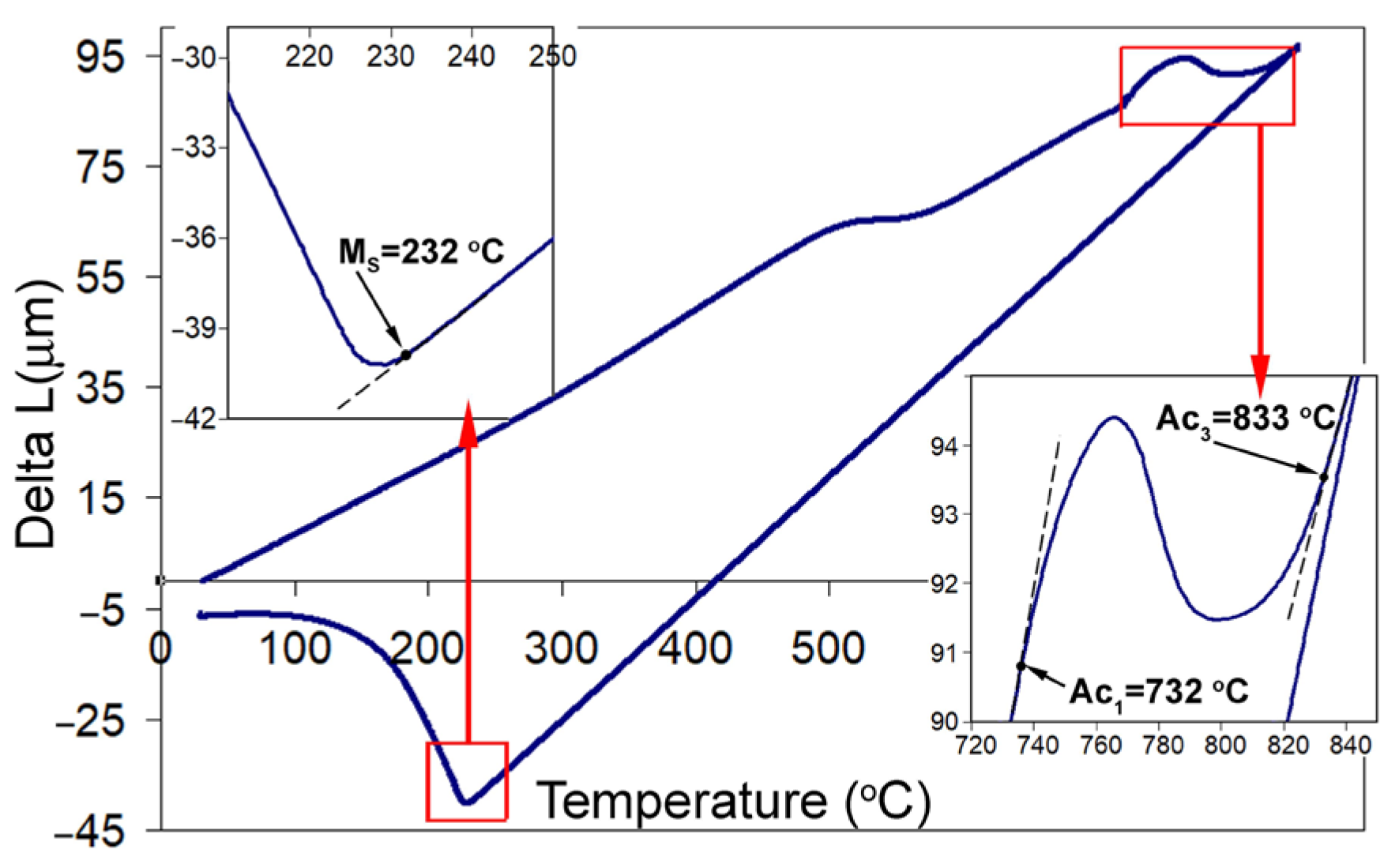
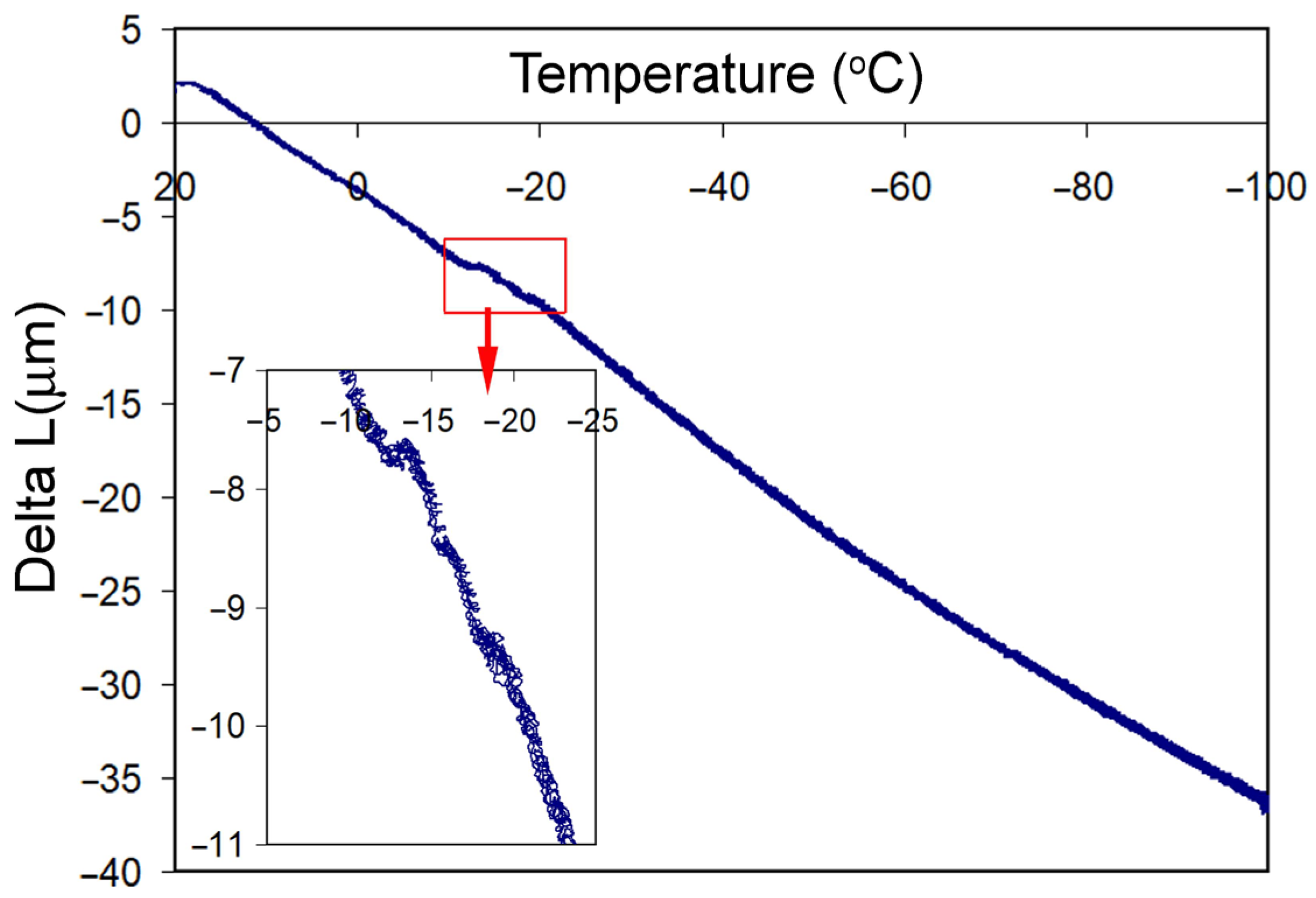
A dilatometric study was performed with a L78 RITA quenching dilatometer (Linseis Messgeräte GmbH, Selb, Germany) on specimens measuring 2 × 2 × 10 mm extracted from the annealed strip to determine the critical temperatures (Ac1, Ac3, and MS). These temperatures were derived from the dilatometric curves using the tangent method (Figure 1). The specimens were heated to 900 °C at a rate of 10 °C/s; the measured Ac1 and Ac3 temperatures were 732 °C and 833 °C, respectively. After holding at 900 °C for 10 min, followed by cooling at 0.5 °C/s, only martensitic transformation was recorded, with a martensite start transformation temperature (Ms) of 232 °C.
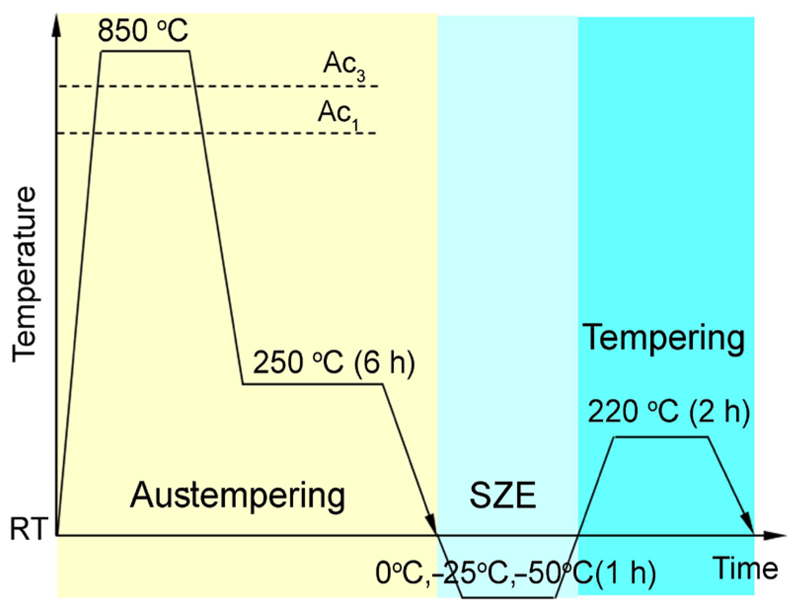
The experiment involved a triple-stage heat treatment consisting of austempering, sub-zero exposure (SZE), and tempering (Figure 2). The austempering parameters were set based on the critical temperatures values, as follows: austenitization at 850 °C, transfer to a salt bath for holding at 250 °C (just above MS) for 6 h, followed by cooling in still air. The austempered specimens were subjected to SZE, which involved holding in an ice-water bath (0 °C) or a liquid nitrogen–alcohol bath (–25 °C or –50 °C), followed by rewarming in still air. The 1 h duration for SZE was chosen to ensure complete thermal stabilization of the specimens. While real service conditions in cold climates involve much longer exposure times, the primary structural changes (i.e., the athermal transformation of retained austenite) occur rapidly. Therefore, the 1 h interval is considered sufficient to capture the permanent degradation of the mechanical properties that would occur under seasonal temperature fluctuations. Some of the SZE specimens were tempered at 220 °C for 2 h, followed by air cooling. For brevity, the specimens are designated as A (austempering), A-SZx (austempering + SZE), and A-SZx-T (austempering + SZE + tempering), where the subscript “x” refers to the SZE temperature (SZ0, SZ–25, and SZ–50—for 0 °C, –25 °C, and –50 °C, respectively).
Tensile and impact tests were carried out in compliance with ASTM E8/E8M [41] and ISO 148-1 [42], respectively. Tensile tests were performed using cylindrical specimens with a 3 mm diameter and a TiraTest 2300 testing machine (TIRA GmbH, Schalkau, Germany) at a constant crosshead speed corresponding to the strain rate of 6.25·10–4 s−1. The yield tensile strength (YS) was determined with the 0.2% criterion. The total elongation (EL) was measured over a gauge length of 40 mm. Charpy impact tests were conducted using a WANCE PIT602H-4 pendulum impact tester (Shenzhen Wance Testing Machine Co., Shenzhen, China). To evaluate the effect of microstructural changes on energy abortion, sub-zero specimens with a cross-section of 5 × 10 mm and a length of 55 mm were used (Mesnager-type, U-notch with a 2 mm depth and 1 mm root radius). Given the high strength level of steel, this notch geometry allows for enhanced sensitivity of the measurements to microstructural variations, which might be suppressed by the high stress triaxiality of a standard V-notch. In accordance with ISO 148-1, the results are primarily reported as absorbed energy (KU) in Joules (J). Additionally, the specific impact energy (KCU, in J/cm2) was calculated by dividing the absorbed energy by the initial cross-sectional area under the notch (0.4 cm2) to facilitate comparison with previously published data on nanobainitic steels. For each heat treatment regime, three tensile and three Charpy specimens were tested for each condition to ensure reproducibility.
Vickers hardness (HV1) was measured on polished cross-sections using a “Vickers 432SVD” (Wolpert Wilson Instruments, Lake Bluff, Il, USA) hardness tester with a load of 1 kgf (9.807 N), with a dwell time of 10 s. The average of at least five measurements per each treatment is reported.
All mechanical tests were performed at ambient room temperature (25 °C). Following the sub-zero exposure (SZE) at various temperatures, the specimens were removed from the cooling chamber and allowed to reach thermal equilibrium with the laboratory environment before testing. This approach allowed for the assessment of permanent microstructural degradations induced by the low-temperature treatment.
Samples for microstructural investigation were extracted from the fractured Charpy specimens and prepared using standard metallographic procedures, including grinding with SiC papers and fine polishing with 1 μm diamond paste. Etching was performed with 4% Nital. Microstructures were examined using a JEOL JSM-7000F field-emission scanning electron microscope (FE-SEM) (JEOL, Tokyo, Japan) equipped an INCAx-sight energy-dispersive X-ray (EDX) detector (Oxford Instruments, High Wycombe, UK). Electron backscatter diffraction (EBSD) analysis was conducted using an Apreo S HiVac Thermo Fisher FE-SEM (Thermo Fisher Scientific, Waltham, MA, USA) operating at 20 kV, with data collected at a step size of 0.05–0.075 μm using a Symmetry S3 EBSD detector (Oxford Instruments, High Wycombe, UK). For transmission electron microscopy (TEM), 3 mm-diameter foils were mechanically thinned and electropolished in a 10 vol.% perchloric acid solution at 20 V and room temperature. Scanning TEM images were obtained using a JEOL JEM-F200 (JEOL, Tokyo, Japan) microscope. The true thickness of bainitic ferrite laths (t) was evaluated from TEM images using the following equations [29,43]:
t = 2 L ¯ T π ,   C I = ± 2 σ L π N ,
where L ¯ T is the mean linear intercept length measured normal to the longitudinal direction of the lath, σL is the standard deviation of intercept length values, N is number of measured bainitic ferrite laths (N = 320, covering seven fields of view ranging from 4 × 4 μm to 5.2 × 5.2 μm), and CI is the 95% confidence interval.
Phase identification and quantification were performed by X-ray diffraction (XRD) on a Bruker D8 Advance diffractometer (Bruker AXS, Billerica, MA, USA) equipped with Co-Kα radiation, Göbel mirror optic, and a LynxEye position-sensitive detector. For the XRD measurements, the specimens were polished with OP-U silica suspension (40 nm particle size). The measurements were carried out in coupled θ-2θ mode over a 35–135° range with a step size of 0.015° and a counting time of 2 s per step. The tube was operated at 40 kV and 30 mA. To calculate residual stresses, a reference XRD pattern was obtained under the same conditions from a stress-free sample. The reference sample was prepared by austenitization at 900 °C, furnace cooling to 600 °C (2 h hold), heating to 650 °C (4 h hold), and final furnace cooling. Phase quantification was performed via Rietveld refinement [44] using the TOPAS software (version 4.2) (Bruker AXS, Billerica, MA, USA). The crystallographic model included standard structural data for ferrite and austenite. The refinement protocol involved lattice parameters, scale factors, background, 2θ-displacement, and the simultaneous determination of crystallite size and lattice strain from diffraction peak broadening. To account for crystallographic texture, the generalized spherical harmonics approach was applied. The carbon contents in bainitic ferrite and retained austenite were calculated using the Honda–Nishiyama [45] and Dyson–Holmes [46] relationships, respectively:
cα/aα = 1 + 0.045xC,
aγ = 3.578 + 0.033xC + 0.00095xMn,
where cα/aα is a tetragonality of bainitic ferrite lattice, aγ is the lattice parameter of austenite (in E); xC and xMn are carbon and manganese contents, respectively (wt. %).

3. Results

3.1. Mechanical Testing

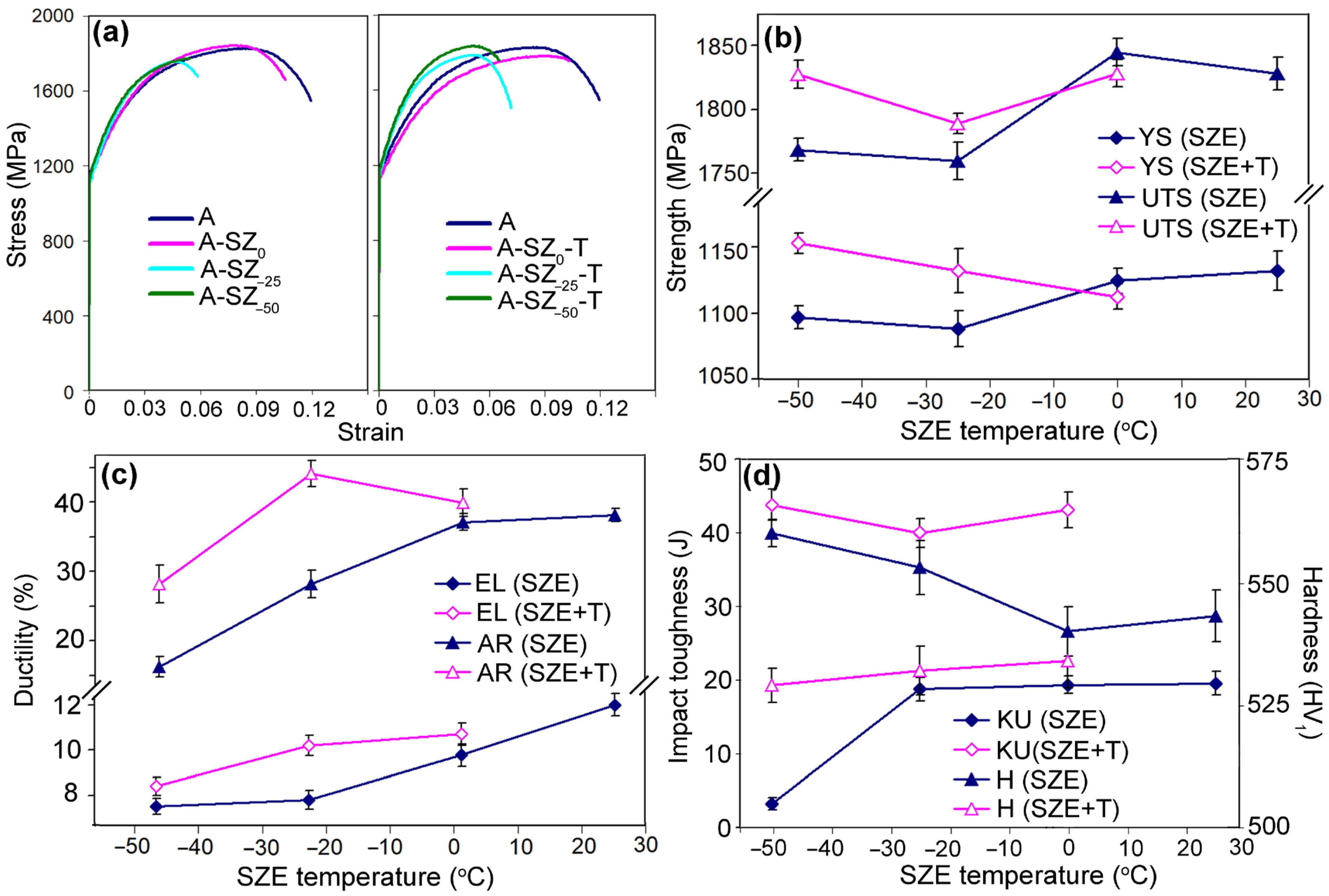
The engineering stress–strain curves obtained from tensile testing are shown in Figure 3a. The yield strength was calculated from the full stress–strain data according to the 0.2% criterion, although the elastic region was omitted in the final plots to highlight the plastic deformation stage. Comparison with the as-austempered reference curve indicates that SZE had minimal influence on the onset of plastic deformation but slightly lowered the maximum load capacity of the samples, while significantly diminishing the steel’s ability to undergo plastic deformation. Tempering largely restored the tensile behavior of the steel depending on the SZE temperature.
Figure 3b–d show the effect of SZE temperature on the residual mechanical properties (measured at room temperature after sub-zero exposure). In the as-austempered state, the steel exhibited the following mechanical properties: yield strength (YS) of 1134 ± 15 MPa, ultimate tensile strength (UTS) of 1826 ± 13 MPa, total elongation (EL) of 12 ± 0.5%, reduction in area (AR) of 38 ± 2%, and U-notch impact energy (KU) of 19.6 ± 1.6 J (equivalent to 49 J/cm2). SZE at 0 °C had virtually no effect on these properties: strength and ductility changed only slightly, within the experimental error, while the impact toughness remained essentially at the as-austempered level (19.4 J). Lowering the SZE temperature to –25 °C led to a noticeable decline in tensile properties relative to the as-austempered state: YS and UTS decreased by 45 MPa and 70 MPa, respectively. Ductility decreased even more significantly (by 27–50%), reaching an EL of 5.7% and AR of 28%. Meanwhile, impact toughness remained practically unchanged (18.8 J). SZE at –50 °C caused a drastic decrease in impact toughness (3.3 J) and a further reduction in ductility, while no additional decline in strength properties occurred. Thus, sub-zero exposure degraded the mechanical properties of the steel and revealed distinct temperature thresholds for degradation: between 0 °C and –25 °C for tensile properties, and between –25 °C and –50 °C for impact toughness. In contrast, a slight but noticeable increase in Vickers hardness was observed, from 543 ± 5 HV1 in as-austempered state to 553 ± 4 HV1 and 560 ± 5 HV1 after sub-zero exposure at –25 °C and –50 °C, respectively, representing a 3–4% increment (Figure 1).
Particular attention was paid to the positive effect of tempering at 220 °C on the recovery of mechanical properties after SZE. Regarding tensile properties, tempering slightly decreased strength and did not affect ductility after SZE at 0 °C. In contrast, for the samples exposed to –25 °C and –50 °C, tempering partially mitigated the SZE-induced degradation: strength properties increased by 30–60 MPa, returning to the as-austempered level (Figure 3b), while EL and AR increased by 1.5% and 11–12%, respectively, relative to the non-tempered SZE state. After SZE at –25 °C, tempering even restored the AR to the as-austempered value (Figure 3c). The most substantial improvement occurred in impact toughness, which—regardless of the SZE temperature—approximately doubled relative to the as-austempered condition, reaching 40–44 J (100–110 J/cm2, Figure 3d). Subsequent tempering at 220 °C resulted in a decrease in hardness to 529–534 HV across all SZE conditions, which is slightly lower than the initial as-austempered level.

3.2. Fractography

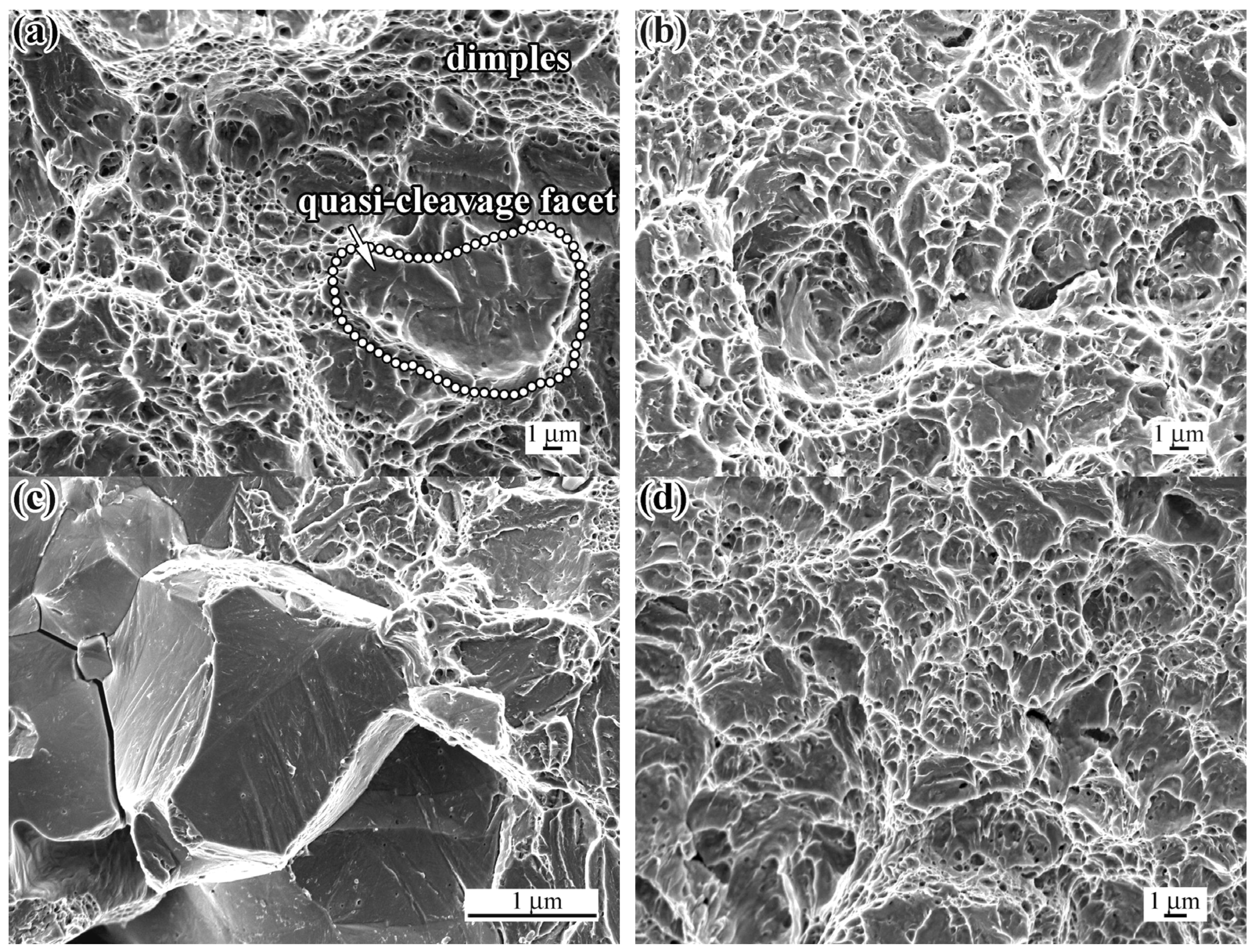
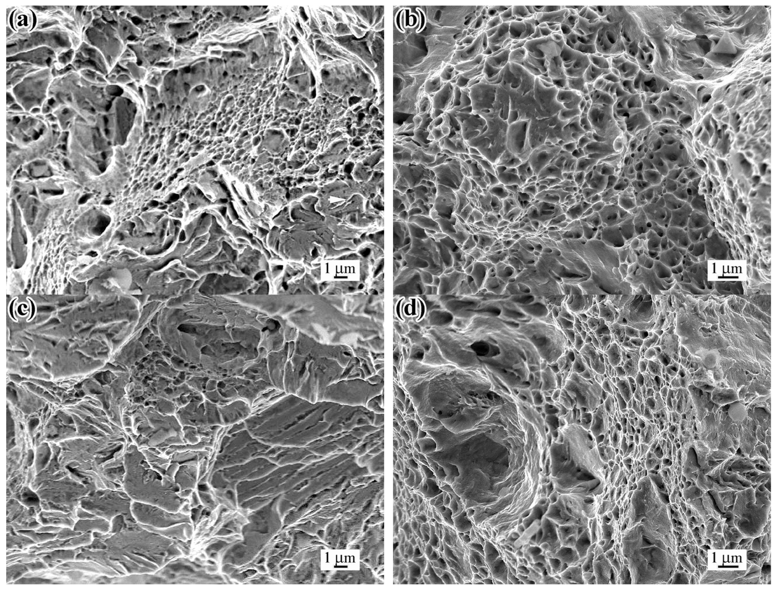
The fracture mechanisms controlling the mechanical behavior of the nanobainitic steel under impact loading were assessed through fractographic analysis. Figure 4 presents the fracture surfaces of the Charpy specimens. Figure 4a shows the fracture surface of an A-SZ0 specimen (KU of 19.4 J), which displays a mixed character, featuring both ductile and quasi-brittle areas. Ductile features are evidenced by the presence of numerous dimples, while the quasi-cleavage mechanism is indicated by flat transgranular facets (outlined by dotted line in Figure 4a) associated with reduced energy absorption. A similar fracture pattern was characteristic of as-austempered specimens, which exhibit nearly identical impact toughness. Overall, dimpled fracture predominates, consistent with the impact toughness level of approximately 20 J. Lowering the SZE temperature to –50 °C caused sharp embrittlement, resulting in a sixfold reduction in KCU. This is manifested by predominantly transgranular quasi-cleavage accompanied by intergranular (“rock-candy”) brittle facets along the prior austenite grain boundaries (Figure 4c). Tempering consistently shifted the fracture mode toward a ductile mechanism, as evidenced by the appearance of a primarily dimpled pattern with only a minor fraction of quasi-cleavage facets (Figure 4b,d). The fracture surfaces shown in these images are consistent with the significantly increased toughness achieved after tempering.
Figure 5 presents the fracture surfaces of the tensile specimens processed under the same conditions as those shown in Figure 4. The overall fracture behavior largely resembles that observed in the impact specimens, highlighting a common rupture mechanism regardless of the loading scheme. The A-SZ0 specimen exhibits a mixture of ductile (dimples) and quasi-brittle (transgranular quasi-cleavage) fracture modes in approximately equal proportions (Figure 5a). Upon cooling to −50 °C, quasi-brittle cleavage facets become dominant on the fracture surface (Figure 5c). Tempering of the A-SZ0 and A-SZ–50 specimens significantly alters the fracture mechanism, replacing brittle transgranular cleavage with a more energy-absorptive process of dimple nucleation and growth (Figure 5b,d).

3.3. Dilatometric Study Under Sub-Zero Cooling

To investigate the possible phase transformation of retained austenite in the as-austempered steel during sub-zero cooling, dilatometric analysis was performed in the temperature range from 25 °C to –100 °C at a cooling rate of 0.1 °C/s. As expected, in principle the specimen exhibited linear thermal contraction with decreasing temperature (Figure 6). However, closer inspection of the dilatometric curve revealed a cascade of small consecutive expansions (low peaks) in the temperature range from –13 °C to –21 °C. These features manifest slight increases in specimen length and can be attributed to the transformation of small portions of retained austenite to martensite. No further deviations or peaks were observed at temperatures down to –100 °C. These results demonstrate the relatively high thermal stability of retained austenite in the austempered steel within the studied temperature range.

3.4. XRD Phase Identification

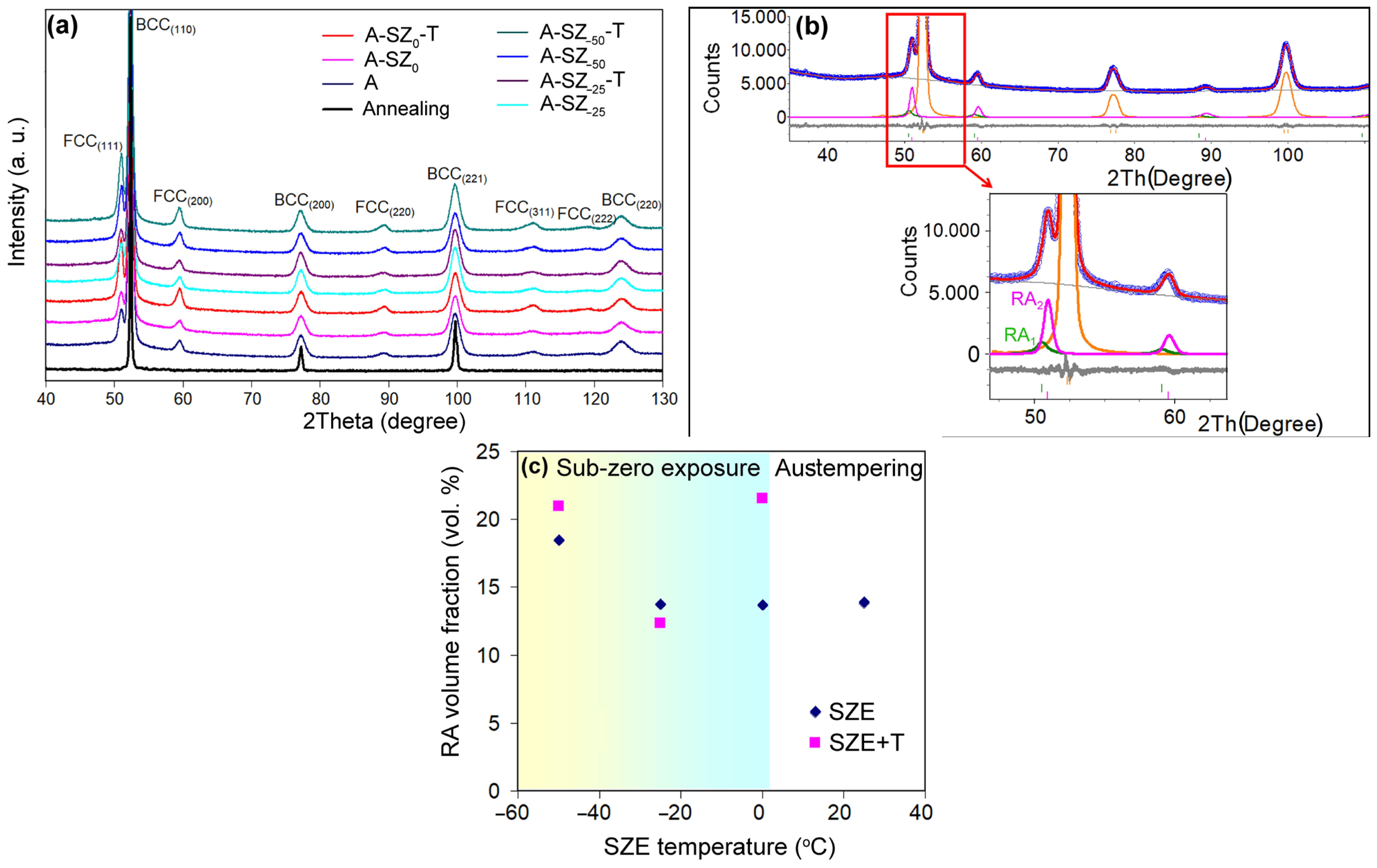
Figure 7a shows the XRD patterns of the investigated specimens, and Figure 7b—a comparison of the observed (blue circles) and calculated (red line) XRD patterns obtained after Rietveld refinement, together with the contribution of the component phases in different colors. The values of the structural parameters obtained from the Rietveld refinement are summarized in Table 1. In all specimens, regardless of the applied austempering regime, only two phases were identified: бFe (BCC) and гFe (FCC). The predominant phase is бFe, which exhibits a nearly cubic lattice with very slight tetragonality (c/a of 1.0075–1.0076), consistent with the characteristics of bainitic ferrite [47]. According to Equation (2), these values correspond to a carbon content in bainitic ferrite of 0.166–0.168 wt% (rounded to 0.17 wt.%). Rietveld refinement (Figure 7b) revealed that the г-phase (retained austenite) exists in two distinct modifications differing in lattice parameter: RA1 with a = 3.6278–3.6310 E and RA2 with a = 3.5972–3.6026 E. This difference in lattice parameters of the two austenite modifications is attributed to variations in carbon content. Using Equation (3), the carbon concentration was calculated as 1.54–1.61 wt.% for RA1 and 0.87–0.99 wt.% for RA2. Based on these values and literature data [48], RA1 and RA2 might be associated with film-like (high-carbon) and blocky (low-carbon) morphologies, respectively. The volume fraction of the low-carbon modification (RA2) was approximately 2.5 times higher than that of the high-carbon modification (RA1).
Based on the volume fractions and carbon concentrations presented in Table 1, the total carbon content in the analyzed specimens was estimated at 0.30–0.37 wt. %, which is lower than the nominal content in the steel. This discrepancy is likely due to a portion of carbon being bound in transition carbides that precipitated inside the bainitic ferrite during the transformation (as shown subsequently).
The total volume fraction of retained austenite ranged from 13.6 to 21.5 vol.%. As shown in Figure 7c, no clear correlation was observed between the total RA content and the heat-treatment parameters, despite the expected trend of reduction with decreasing SZE temperature. On the contrary, the RA volume fraction after SZE at –50 °C exceeded that obtained after austempering. It is evident that the amount of retained austenite was affected neither by SZE nor by tempering; rather, it was governed by other factors. A slight apparent increase in the RA fraction after tempering should be interpreted as a statistical artifact caused by Mn/Si segregation, as discussed in detail in Section 4.3.

3.5. Microstructure Observation

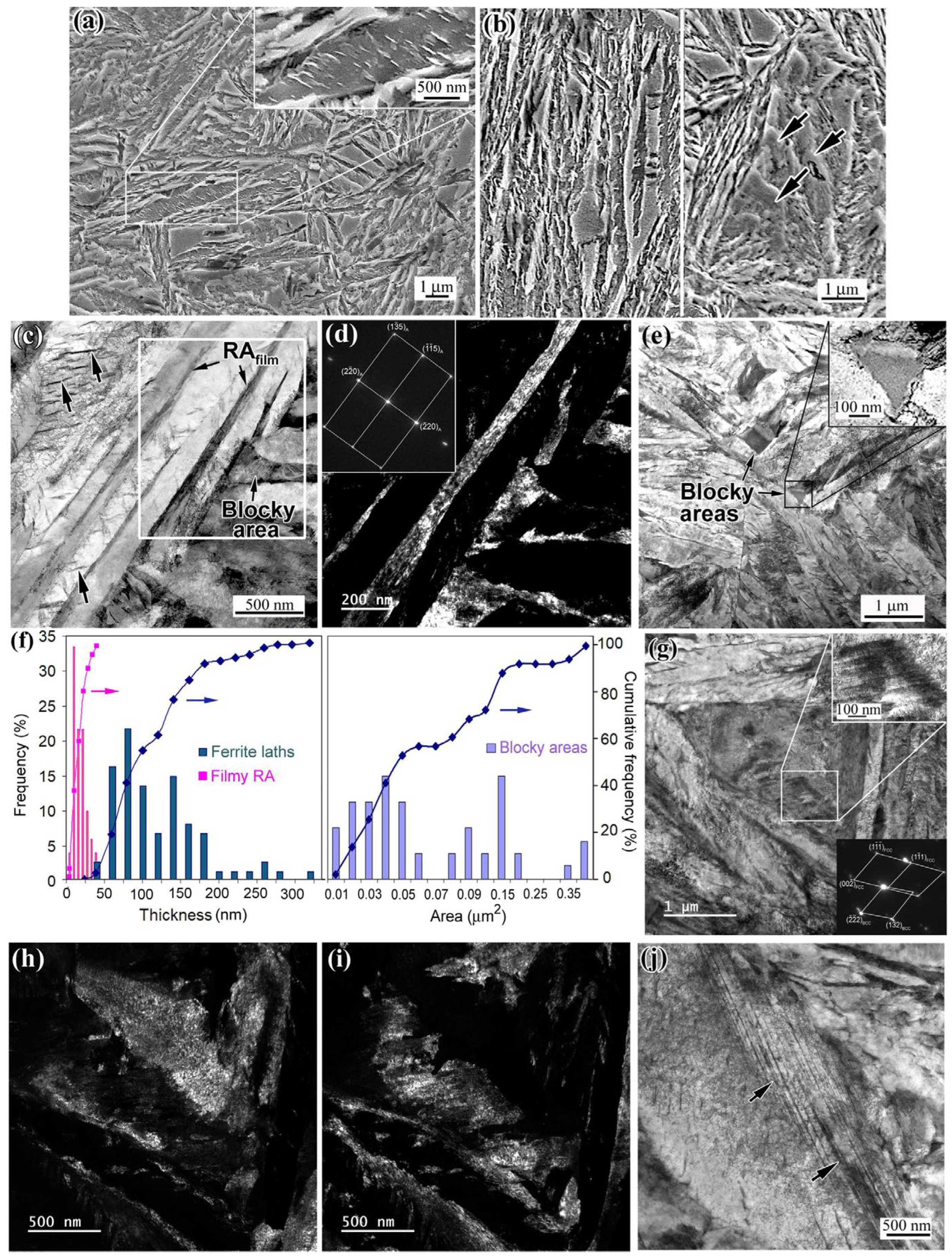
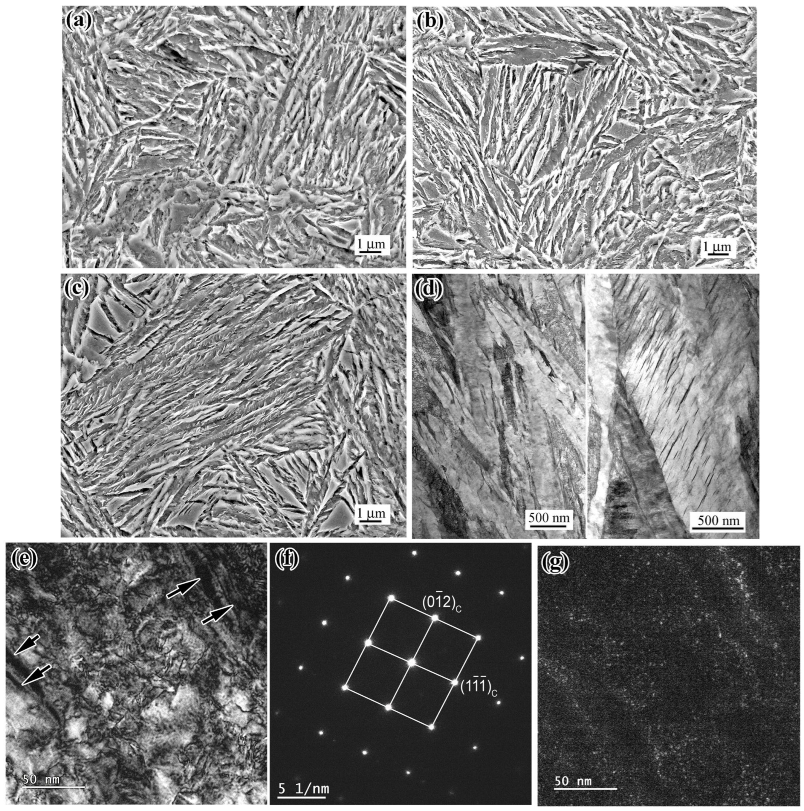
The microstructure of the as-austempered specimen consists of sheaves of ferrite plates randomly oriented within prior austenite grains (Figure 8a). Depending on their orientation relative to the observation plane, the bainite sheaves appear either as parallel thin laths (in the perpendicular plane, Figure 8b, left) or as a terrace-like structure (in the parallel plane) composed of overlapping plates (indicated by arrows in Figure 8b, right). Within some laths, fine transition carbides were observed, precipitated along planes inclined at approximately 55° to the long axis of the lath (inset in Figure 8a). This specific arrangement of the precipitation planes indirectly confirms that the г ⟶ б transformation during bainite formation followed the Kurdjumov–Sachs orientation relationship [49].
Detailed TEM observation revealed the intrinsic features of the bainitic structure, which consists of packets of ferrite laths, as well as blocky and filmy areas of retained austenite (Figure 8c). The presence of retained austenite was confirmed by dark-field imaging and selected area electron diffraction (SAED) patterns (Figure 8d). No carbides were observed at the lath boundaries; instead, fine, elongated transition carbides (less than 20 nm thick) were detected inside the ferrite laths (indicated by arrows in Figure 8c). The ferrite laths exhibit a high dislocation density and varying width. The laths thickness in Figure 8c ranges from 27 to 145 nm (average: 72.2 ± 3.7 nm), while the film-like RA thickness ranges from 10 to 39 nm (average: 21.1 ± 6 nm). In contrast, Figure 8e shows packets with coarser ferrite laths (28–417 nm; average: 156.2 ± 9.7 nm), while the austenite films remain nanosized (7–52 nm; average: 20.8 ± 1.4 nm). Generalized data from seven TEM images (Figure 8f) show bainitic lath thickness ranging from 25 to 320 nm (average: 112.2 ± 5.2 nm), with 54% of laths being thinner than 100 nm. The RA films are significantly finer (4–33 nm; average: 14.0 ± 0.7 nm). These average values are in close agreement with the crystallite sizes of ferrite (99.6 nm) and RA1 (7.9 nm) determined by XRD (Table 1). In addition to laths and films, coarse blocky regions with a nearly triangular morphology were observed at the junctions of bainite sheaves (Figure 8e, inset). The minimum side length of these regions ranges from 0.11 to 1.34 μm (average: 0.29 ± 0.05 μm). Approximating these regions as triangles, their area ranges from 0.0056 to 0.384 μm2 (average: 0.083 ± 0.03 μm2). The area distribution (Figure 8f, right) shows that 59.3% of blocks are ≤0.06 μm2, 33.3% range from 0.08 to 0.20 μm2, and 7.4% are between 0.35 and 0.40 μm2.
These blocky areas consist of a mixture of RA and fresh martensite, consistent with Zhou et al. [48]. Evidence of martensite is provided by internal twins (shown in the inset of Figure 8g). The two-phase state of the block shown in Figure 8g is confirmed by the SAED patterns revealing both BCC and FCC reflections (the inset of Figure 8g). Dark-field images illustrate the coexistence of FCC (Figure 8h) and BCC (Figure 8i) within the same block. Twins were also observed adjacent to the “RA/ferrite lath” interface (Figure 8j).
Sub-zero exposure did not result in any SEM-detectable microstructural alterations, regardless of the SZE temperature (Figure 9a–c). Subsequent tempering at 220 °C primarily preserved the lath morphology (Figure 9d) but induced TEM-detectable in the martensite within blocky areas. This martensite partially decomposed into chains of nanosized carbides (several nanometers in size), primarily aligning with the twins (indicated by arrows in Figure 9e), which act as preferential nucleation sites. This observation was confirmed by SAED (Figure 9f) and dark-field imaging (Figure 9g), which revealed cementite precipitates. A similar morphology of carbides along the {112} twin plane in high-carbon martensite was previously reported by Liu et al. [50].

3.6. EBSD Characterization

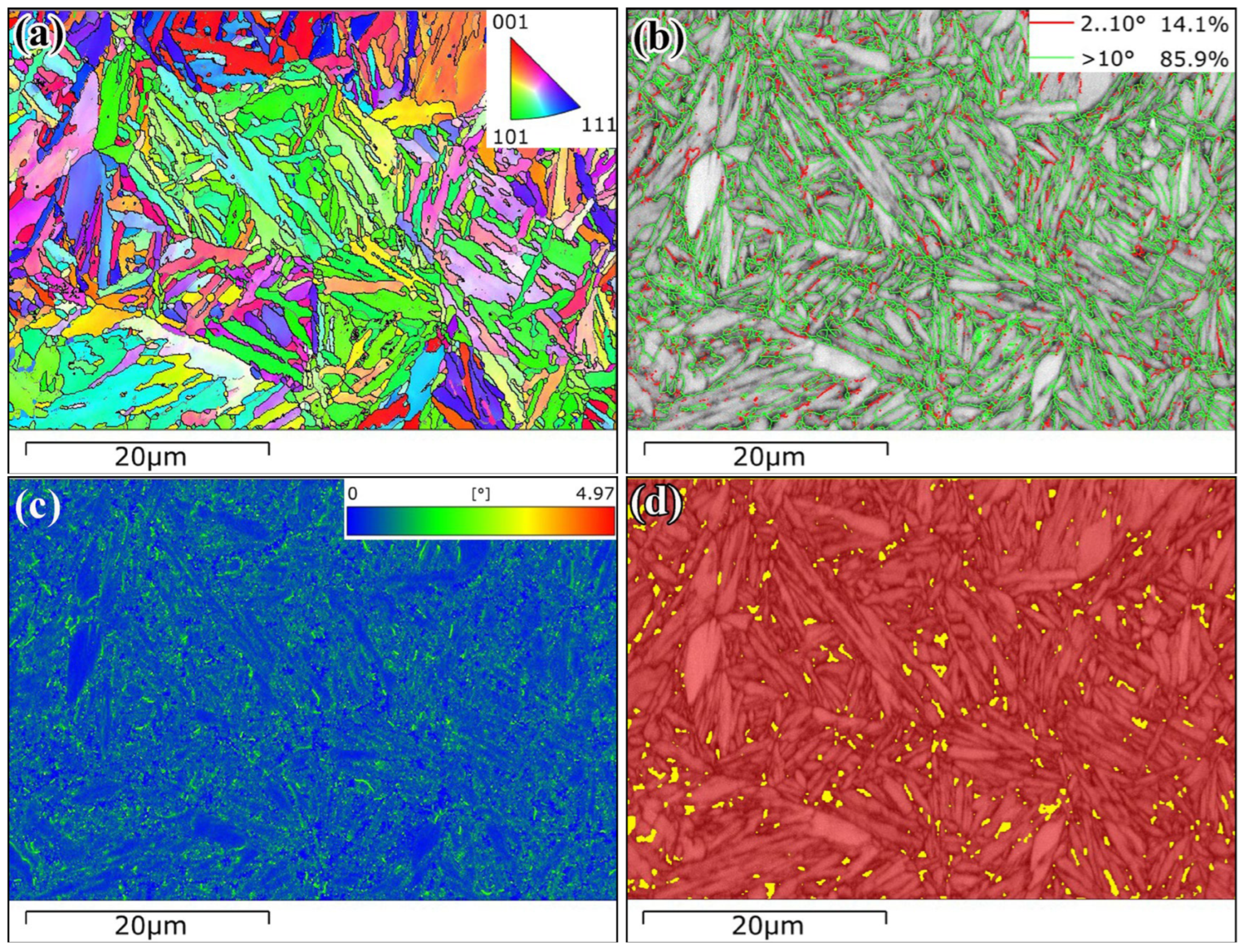
Figure 10 presents EBSD data for the as-austempered specimen. According to the inverse pole figure (IPF) map (Figure 10a), packets of bainitic laths formed within prior austenite grains, exhibiting specific crystallographic orientations that differ significantly from those of neighboring grains. The laths are predominantly separated by high-angle grain boundaries (HAGBs), which account for 85.9% of the boundaries (Figure 10b). The low-angle grain boundaries (LAGBs, 14.1%) are located at lath junctions or within the laths; these result from local plastic strain and are closely associated with local lattice distortions, as evidenced by the kernel average misorientation (KAM) map (Figure 10c). The KAM values range from 0° to 4.97°, with an average of 0.56°, indicating a moderate level of microstrain within the microstructure.
Using the mean KAM value, the density of geometrically necessary dislocations (GNDs) was calculated according to the Kubin–Mortensen relationship [51]:
ρ G N D = α θ b Δ x ,
where и is the average local misorientation measured across a distance Δx (taken as the EBSD step size of 0.075 µm [52]); b is the magnitude of the Burgers vector (2.5 Ч 10−10 m [53]); and б is a geometric constant depending on the boundary type (taken as 2 for a pure tilt boundary [54]).
Equation (4) yields a GND density of 1.04 Ч 1015 m−2, which is consistent with values typically reported for nanobainitic structures [55]. The phase map (Figure 10d) identifies two phases: BCC (ferrite, major phase, in red) and FCC (retained austenite, minor phase, 2.41 vol.%, in yellow). The retained austenite is dispersed throughout the bulk, appearing as thin films between the ferrite laths and as blocks at lath junctions.
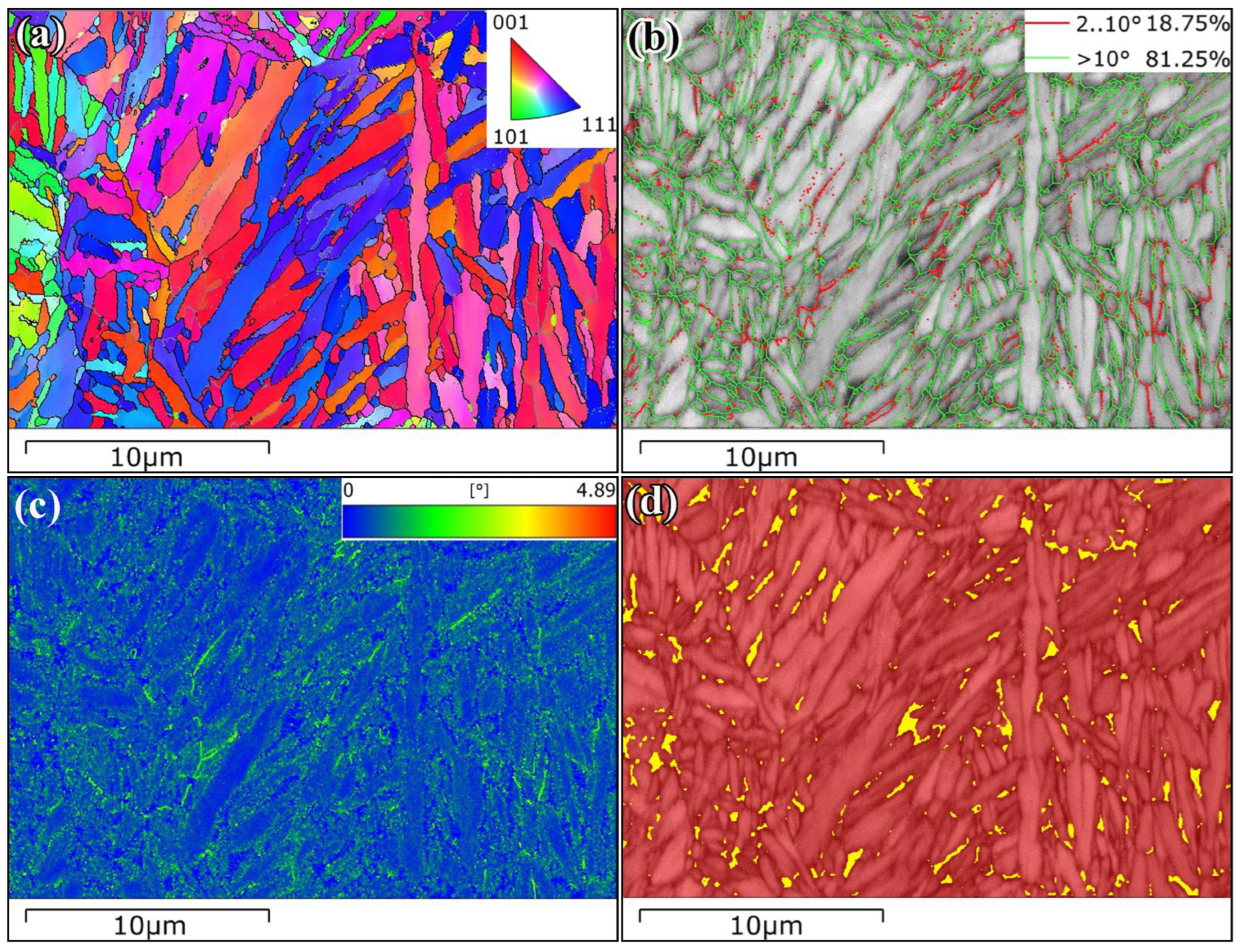
Figure 11 presents the EBSD results for the specimen subjected to SZE at –50 °C. Comparison with Figure 10 reveals no significant differences in the overall crystallographic texture between the two specimens (Figure 10a and Figure 11a). The proportion of HAGBs to LAGBs also remains similar (81.3%:18.7%), as does the KAM distribution, with values ranging from 0° to 4.89° and an average of 0.54° (Figure 11b,c). Using the EBSD step size of Дx = 0.05 µm, the GNDs density was calculated to be slightly higher than that of the as-austempered sample (1.51 Ч 1015 m−2).
The phase map (Figure 11d) shows both blocky and film-like retained austenite, with a measured volume fraction of 3.55 vol. %, which is approximately 1 vol. % higher than in the as-austempered specimen. However, this value remains significantly lower than the RA content determined by XRD. This discrepancy is a well-known limitation of the EBSD technique, particularly in the presence of nanosized RA [56].

4. Discussion

4.1. Effect of Moderate Sub-Zero Temperatures on Nanobainite Mechanical Behavior

The evaluation of the steel’s performance after a cooling–rewarming cycle is of particular importance for structures operating in cold-climate regions. In such environments, seasonal temperature fluctuations directly affect the structural stability and long-term reliability of high-strength components. The experimental results presented in the previous sections raise a critical question regarding the nature of the observed degradation: is the loss of toughness a temporary effect of the cold, or an irreversible microstructural change? By testing the specimens at room temperature after sub-zero exposure, we isolated the permanent damage from the transient low-temperature effects. The following discussion focuses on how these irreversible changes correlate with the original as-austempered state and identifies the primary physical mechanisms that drive this degradation.
As shown by the results, after SZE at 0 °C, all of the returned mechanical properties are practically equivalent to those of the as-austempered state. Noticeable degradation begins after SZE at –25 °C, with a significant decrease in both strength and ductility, while impact toughness remained at the initial level. Cooling to –50 °C led to an even greater reduction in ductility and a sharp drop in impact toughness. Overall, decreasing the SZE temperature progressively reduces the mechanical properties of nanobainitic steel through increasing embrittlement. This phenomenon may be caused by several structural factors arising during sub-zero cooling, specifically:
  • Martensitic transformation of retained austenite [57].
  • Carbon rejection from lattice induced by lattice thermal contraction (transition carbide precipitation) [58].
  • The formation of residual thermal stresses during cooling, including transformation strains and thermal misfit strains [59,60].
The first factor induces embrittlement through the introduction of a brittle phase (martensite). The martensite formed in NBS is always highly tetragonal (and thus more brittle) because it originates from retained austenite with a high carbon concentration. The formation of tetragonal martensite leads to lattice distortion and significant internal stresses, which generates new lattice defects to accommodation. Both effects contribute to high internal stress and reduce ductility [61]. This scenario (the RA ⟶ martensite transformation) is possible when the steel operates below the MS temperature. The MS value for the retained austenite can be estimated using the empirical equation developed and optimized for high-carbon steels [62], which accounts for the steel’s chemical composition:
MS =1/8{4241.9 − 2322.27xC − 284xMn − 54.4xSi − 166.4xCr − 137.4xNi − 83.5xMo − 30xAl + 38.58xCo − 600[1 − exp(−0.96xC)]},
where the concentrations of the elements (xC, xMn, xSi, xCr, xNi, etc.) are given in wt.%.
Carbon contents for the different austenite types (RA1 and RA2) were taken from Table 1. Additionally, manganese enrichment of film-like retained austenite (RA1) was accounted for by applying a concentration 1.5 times higher than the average steel composition [63]. The calculated Ms values are listed in Table 1. For the high-carbon austenite (RA1), the MS temperature lies below –100 °C (from –131 °C to –152 °C); consequently, this austenite could not transform during the SZE. For the low-carbon austenite (RA2), the calculated MS (90–128 °C) is much higher than room temperature, suggesting that RA2 should not be totally retained after final cooling following austempering. However, its presence in the microstructure is confirmed by XRD and EBSD studies. It can be assumed that a portion of the low-carbon austenite (associated with blocky morphology) underwent martensitic transformation within the range between –13 °C and –21 °C (Figure 6). This implies that its true MS temperature lies below 0 °C, which is more than 100 °C below the calculated value. Such a discrepancy arises from the strong mechanical stabilization characteristic of retained austenite in nanobainitic structure. In addition to chemical stabilization, mechanical stabilization substantially increases the thermodynamic driving force required for the onset of martensitic transformation. This stabilization results from the constraining action of surrounding bainitic ferrite laths and fresh martensite, which restrict the plastic accommodation and volume expansion associated with the phase transformation of austenite [64,65]. Since models like Equation (5) do not account for these structural factors, the calculated Ms values exceed the true ones.
Despite the documented martensite transformation (between −13 °C and −21 °C), the transformed volume was minor, as evidenced by the weak dilatometric signal and the lack of a clear trend toward decreasing RA volume fraction with lower SZE temperatures (Figure 7c). Furthermore, no increase in carbon content was observed in the remaining RA upon lowering the SZE temperature—a change expected if the lower-carbon austenite had fully transformed. Consequently, only a portion of the RA2 transformed into martensite during SZE. Given the variability in block sizes, transformation likely occurred preferentially in the largest blocks (0.35–0.40 µm2, according to Figure 8f), which exhibit the lowest chemical and mechanical stability. Although the transformed volume was small, this partial transformation might contribute to the mechanical properties degradation, specifically the significant decrease in tensile properties following SZE at −25 °C.
Another potential mechanism of embrittlement in nanobainitic steel during SZE is carbon rejection from bainitic ferrite laths driven by lattice contraction upon cooling [60]. The rejected carbon might be absorbed by retained austenite, increasing its specific volume and generating local stresses. However, this effect is likely counterbalanced by the toughening of bainitic ferrite due to carbon depletion [59]. Alternatively, the rejected carbon could precipitate as transition carbides or cementite [61]. In such cases, both applied and residual stresses might relax through transformation-induced plasticity governed by the Greenwood–Johnson mechanism [59,66,67]. Nevertheless, cold-driven carbide precipitation appears unlikely here. First, such a process typically requires substantial undercooling to liquid nitrogen temperatures to achieve a large magnitude of thermal contraction [68]. Second, TEM examination of a specimen cooled to –50 °C (Figure 9d) revealed no discernible increase in carbide content compared to the as-austempered state.
Consequently, the residual thermal stresses are considered the dominant factor responsible for the SZE-induced degradation of nanobainitic steel properties [69,70]. These stresses may primarily originate from non-uniform thermal contraction caused by the composite nature of the nanobainitic microstructure, containing extensive interphase boundaries. The internal thermal stresses induced by SZE are predominantly localized at the interfaces between bainitic ferrite and retained austenite (as well as other phases such as carbide and martensite) due to the mismatch in their coefficients of thermal expansion (CTE, αT). The values of αT for bainitic ferrite and retained austenite are (1.507–1.631) × 10−5 K−1 and (2.338–2.423) × 10−5 K−1, respectively [71]. For martensite, αT values fall within the range (1.45–1.65) × 10−5 K−1 according to data reported for steel grades SAE 4140, SAE 52100, and SAE H13 [72]. For bainite-associated cementite carbide at temperatures below the Curie point, αT is 0.56 × 10⁻⁵ K−1 [73]. The thermal stresses at the interface can be estimated in the first approximation as follows:
Δ σ = Δ α T E Δ T ( 1 μ ) ,
where ΔαT represents the CTE mismatch, E is the Young’s modulus (185 GPa for nanobainite [74]), ∆T is the temperature change during cooling, and µ is Poisson’s ratio (0.3 [75]).
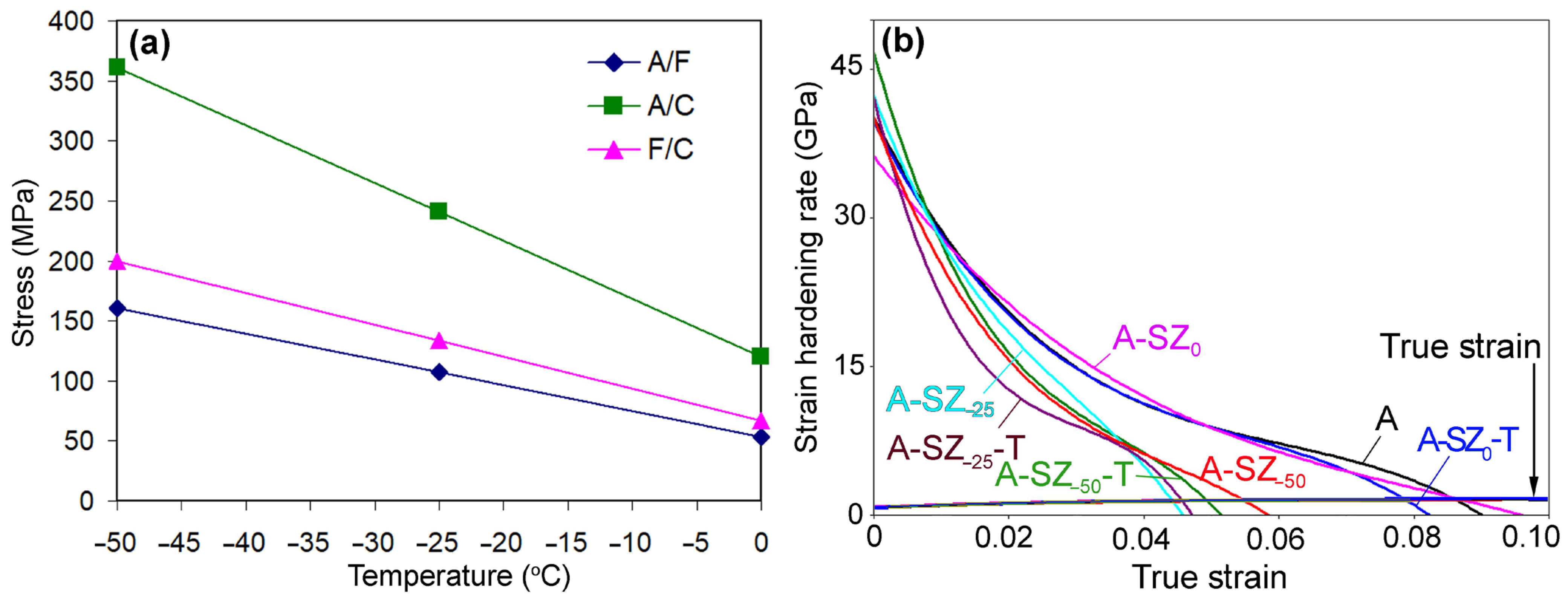
Figure 12a shows the variation in thermal stresses for different phases couplings under progressive cooling. For the largest temperature drop considered (from 25 °C to –50 °C), the local interfacial stresses can reach 161.8 MPa (ferrite/austenite), 205.3 MPa (ferrite/cementite), and 365.7 MPa (austenite/cementite). The stresses for the martensite coupling are equivalent to those of ferrite. In previous study [48], the hardness of film-like retained austenite in a medium-carbon nanobaintic steel was measured at 2.76–4.38 GPa, with an average value of 3.15 GPa. Based on the established correlation between yield strength and hardness for steels with non-martensitic microstructures (YTS (MPa) = –90.7 + 2.65 Ч HV [76]), the yield strength of the retained austenite can be estimated to be 641–1070 MPa. These values substantially exceed the thermal stress levels calculated above. Consequently, the thermal stresses are insufficient to induce plastic deformation in either bainitic ferrite or retained austenite; therefore, they remain as residual stresses, generating local stress concentrations that promote embrittlement. Interfacial stresses of 200–366 MPa at matrix/carbide interfaces can increase strength by impeding dislocation motion, yet simultaneously create sites of interfacial decohesion or carbide cracking, ultimately degrading both strength and ductility. Furthermore, the estimated stress of ~162 MPa at ferrite/retained-austenite interfaces may stimulate DIMT, potentially causing earlier embrittlement during loading [77,78]. However, an analysis of the strain hardening rate (SHR) curves for different heat treatment regimes (Figure 12b) reveals no discernible differences in their shape that would indicate changes in DIMT kinetics. Notably, none of the curves exhibit an upward-sloping region that could be attributed to a significant TRIP effect during work hardening. Therefore, SZE-induced brittleness is not caused by alterations in DIMT kinetics.
Additional mechanisms potentially contributing to local residual stresses during SZE include: (a) the disparity in the temperature dependence of the elastic moduli of BCC and FCC phases (the former changes more significantly) [79]; (b) reduced dislocation mobility at low temperatures, which hinders micro-scale stress relaxation [80,81]; (c) the heterogeneity of microstructural constituents and their distribution (coexistence of blocky and filmy retained austenite, bainitic plates of different thicknesses and dislocation densities, and the presence of carbides, etc.), which further impedes uniform thermal contraction and promotes non-uniform stress distribution [82,83].
Analysis shows that different mechanical properties respond markedly differently to decreasing SZE temperature, exhibiting distinct degradation threshold. Tensile properties degraded at –25 °C, while impact toughness significantly deteriorated only after cooling to –50 °C. These observations suggest that different loading conditions (stress–strain states) produce distinct responses in the nanobainitic microstructure to SZE-induced embrittlement. Overall, cooling to –50 °C degraded all mechanical properties; even after rewarming to room temperature, tensile properties remained substantially below the original as-austempered level. These findings raise doubts regarding the suitability of high-strength nanobainitic steels for applications in sub-polar climate conditions without additional treatment.

4.2. Mitigation of SZE Degradation by Stress-Relief Tempering

The present work demonstrates that tempering at 220 °C effectively restores SZE-degraded properties. This beneficial effect is primarily attributed to the relief of residual stresses. At temperatures around 200 °C, stress relaxation occurs predominantly through thermally activated atomic mobility, enabling limited plastic flow (low-temperature creep) [84]. This process converts elastic strains into plastic ones, thereby reducing internal stress imbalances and local stress concentrations without significantly altering the microstructure or strength [85,86]. The minimum (steady-state) creep rate ( ε ˙ ) is described by the Bird–Mukherjee–Dorn equation, modified by including a threshold stress (σth), below which creep is negligible [86,87]:
ε ˙ = A D E b k T σ σ t h E n b d p ,
where A is a dimensionless constant, D is the diffusivity, k is the Boltzmann constant, E is the Young modulus, b is the Burgers vector, d is the grain size, p is the inverse grain-size exponent, n is the stress exponent.
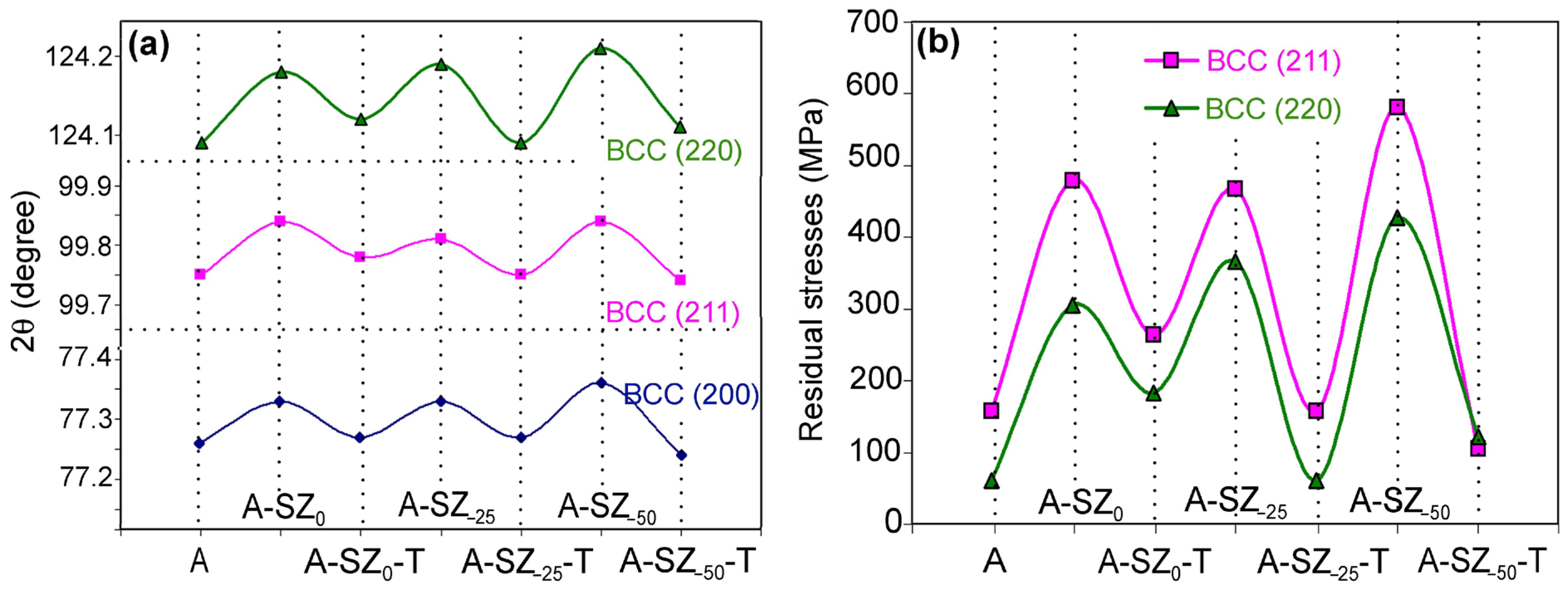
The above relationship was previously used in [86] to experimentally determine the threshold stress for low-temperature creep in 300M martensitic steel, which has a composition similar to that of the nanobainitic steel studied here. At 200 °C and for stress exponents n ranging from 7 to 9 [86], the creep activation threshold was found to vary between 106.3 and 145.2 MPa. These values are lower than the interfacial stresses calculated above for cooling to –50 °C (Figure 12a). Consequently, tempering at 220 °C can initiate creep-assisted relaxation of residual stresses, ultimately improving the overall mechanical performance of the nanobainitic steel. Evidence of this stress relaxation is provided by the data in Figure 13a, which illustrates the variation in the positions of the ferritic (200), (211), and (220) diffraction peaks under different processing conditions. A clear cyclic pattern is evident: SZE treatment causes a shift in the peaks to higher angles, while subsequent tempering shifts them back to lower angles, approaching the original positions observed in the as-austempered condition. These variations indicate changes in interplanar spacing and can be attributed to the buildup and subsequent relaxation of residual stresses [88].
The XRD shift data were used for the first-approximation evaluation of the residual macro-stresses (σS) by considering the difference in the interplanar spacing (dhkl) compared to a stress-free reference (d0) [89]:
σ S = E μ ( d d 0 ) d 0 ,
where d0 values are derived from the XRD pattern of the annealed specimen; E and μ are given above (see Equation (6)). The d values were calculated using Bragg’s law. Diffraction peaks in the high-angle region, specifically BCC (220) and BCC (211), were selected to minimize the error in interplanar spacing calculation.
The residual stress calculations results are shown in Figure 13b. The stress variation exhibits an oscillatory profile, consistent with the peak shift behavior (Figure 13a): sub-zero treatment increases the stresses, while subsequent tempering reduces them to a level close to the initial state. A trend of increasing stress is observed as the cooling temperature decreases, reaching 426 MPa (for the BCC (220) line) and 580 MPa (for the BCC (211) line). After tempering, residual stresses in most cases do not exceed 200 MPa. A comparison of the data in Figure 3 and Figure 13 shows that changes in mechanical properties correlate with the residual stress dynamics. The lack of significant hardness increase and dilatometric expansion, coupled with high XRD stress values, identifies internal stresses as the primary cause of the SZE-degradation phenomenon.
SZE with holding at 0 °C did not cause degradation of the mechanical properties, indicating that the steel condition after SZE remained close to the as-austempered state. However, tempering following SZE at 0 °C resulted in a pronounced increase in impact toughness, which represents an intrinsic tempering response of the as-austempered microstructure. This suggests that the as-austempered steel contained structural element(s) that affect impact toughness and respond to heating at 220 °C. It is believed that this element is martensite, which may form in nanobainitic steel during the final cooling after the austempering stage. This assumption is supported by TEM observation of as-austempered specimen, which revealed twins—a characteristic feature of high-carbon martensite (Figure 8g,j). The decomposition of this martensite serves as a potential stress-relief mechanism during post-SZE tempering.
Martensite likely originates in nanobainite from blocky retained austenite with an Ms exceeding room temperature (25 °C). According to Equation (5), the carbon content in this austenite could reach approximately 1.20 wt.% C. As demonstrated earlier, mechanical stabilization of austenite in nanobainite decreases the Ms by about 100 °C, equivalent to lowering the critical carbon content to 0.88 wt.%. At this concentration, tetragonal martensite forms, exhibiting a c/a ratio of 1.039 per the Honda–Nishiyama relation (Equation (3)) [3]. This leads to a highly distorted lattice and significant internal residual stresses, reducing impact toughness [90]. However, in the as-austempered structure, the embrittling effect of fresh martensite is counterbalanced by the coexistence of low-tetragonality bainitic ferrite (c/a ≤ 1.008, Table 1) and ductile retained austenite, which together ensure satisfactory ductility (EL of 12%) and adequate impact toughness (19.6 J). During the sub-zero exposure, the formation of additional portions of fresh martensite introduces new local stress concentrations, promoting crack nucleation and propagation under dynamic loading.
Since martensite is a metastable phase, it responds to heating through decomposition and loss of tetragonality. As shown by Zheng et al. [86], this process initiates upon heating in the 25–100 °C range from carbon segregation; due to the limited diffusion mobility, trapped carbon atoms can only migrate over short distances, thereby reducing elastic lattice distortion. In the subsequent heating range (100–270 °C), nanosized hexagonal e-carbides precipitate as elongated strips within the martensitic plates [86]. The segregation and precipitation of carbon decrease the c/a ratio, reducing lattice distortion and internal stresses, and release pinned dislocations, consequently improving toughness with only minor strength loss [91]. As reported in [70], tempering at 220 °C reduced the martensite tetragonality in quenched bearing steel SAE 52100 (1.5% Cr, 0.10% Mo) from the range of 1.03–1.035 to ≈1.012. An even more pronounced reduction is expected in the studied nanobainitic steel due to the absence of Cr and Mo, both of which retard carbon diffusion and hinder early-stage martensite decomposition [92]. Consequently, the dramatic increase in impact toughness after SZE at 0 °C followed by tempering is primarily attributed to the decomposition of martensite formed during austempering, which eliminated local brittleness. The precipitation of carbon decreases the c/a ratio, reducing lattice distortion and internal stresses, and release pinned dislocations, consequently improving toughness with only minor strength loss [91]. This mechanism is directly supported by the TEM observations (Figure 9g), which reveal the formation of nanosized ε-carbides within the martensitic regions after tempering at 220 °C. Although direct measurements of the c/a ratio in martensite areas were not performed in this study, the presence of these precipitates provides a qualitative confirmation of the martensite decomposition. This reduction in solid-solution carbon density significantly lowers the Peierls–Nabarro stress for dislocation movement, which explains why the toughness not only recovers but doubles compared to the as-austempered state. A similar mechanism likely operated during the tempering of specimens exposed to SZE at –20 °C to –50 °C, where the observed toughness improvement arose from both the relaxation of thermal residual stresses (via low-temperature creep) and the reduced tetragonality of fresh martensite formed during either austempering or SZE.

4.3. Reasons for Increased Scatter of RA Fractions

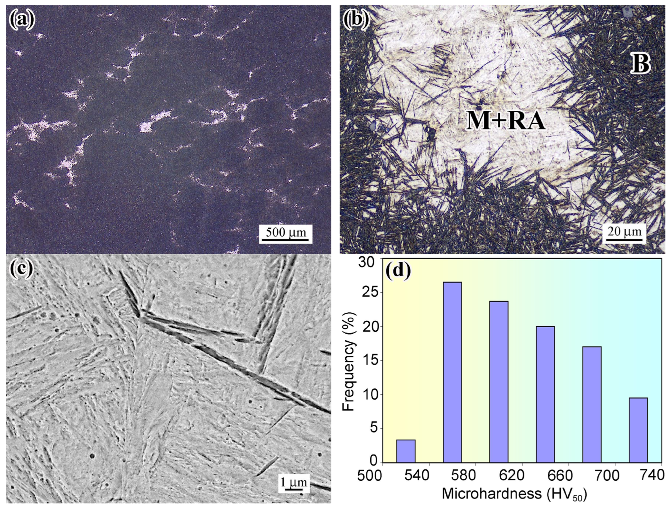
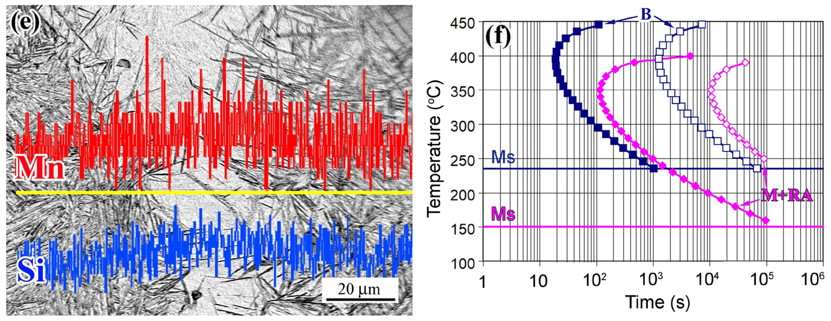
The XRD analysis yielded rather unexpected results concerning the volume fraction of retained austenite in specimens subjected to different SZE regimes. The RA content varied over a wide range (13.60–21.49 vol.%) with no discernible correlation between the austenite fraction and any processing parameter, including SZE temperature (Figure 7c). Thus, there is no XRD evidence to suggest that austenite transformed during either sub-zero cooling or tempering at 220 °C. Such significant sample-to-sample fluctuations in phase composition are attributed to inherent chemical inhomogeneity within the bulk of the steel billet. This heterogeneity was identified during a low-magnification microstructure examination of an austempered sample. Figure 14a shows the microstructure of a 2.7 × 3.5 mm area, where bright regions are visible in the form of a discontinuous network, with their area and distribution varying randomly throughout the sample. At higher magnification, these bright areas are situated between dark bainite fields (Figure 14b) and exhibit a structure characteristic of acicular martensite (Figure 14c). The microhardness of the bright areas varied from 524 to 714 HV50, with half of the measurements falling below 600 HV50 (Figure 14d). Such a spread in microhardness indicates that the bright areas likely consist of a mixture of high-carbon martensite and retained austenite (M + RA), the ratio of which varies widely and, as shown by EDS analysis, depends on the distribution of chemical elements.
As illustrated in Figure 14e, the M + RA regions are enriched with Mn and Si relative to the adjacent bainitic regions. Local composition measurements revealed that the M + RA regions contained 3.7–5.3 wt.% Mn (average: 4.5 ± 0.4 wt.%) and 2.0–3.1 wt.% Si (2.9 ± 0.1 wt.%). Meanwhile, the bainitic areas contained 2.3–3.2 wt.% Mn (3.1 ± 0.2 wt.%) and 1.9–2.9 wt.% Si (2.3 ± 0.2 wt.%). Thus, the alloying element content in the M + RA regions was 1.5 times higher for Mn and 1.3 times higher for Si, which predetermined the different transformation behavior during austempering. Figure 14f presents Time-Temperature-Transformation (TTT) diagrams calculated using JMatPro for two steel compositions with Mn and Si contents corresponding to the average concentrations in the bainitic (blue curves) and M + RA (pink curves) regions. These compositions differ in their martensite start temperatures (235 °C and 150 °C, respectively) and austenite stability in the bainitic transformation range [93]. According to the TTT diagrams, completion of the bainitic transformation at 250 °C in the enriched regions requires 2.6 times longer holding than in the bainitic regions, amounting to ~90,400 s, which significantly exceeds the holding time used in the experiment (21,600 s). Consequently, the enriched zones remained austenitic until the completion of austempering and partially transformed into martensite during final cooling, thus forming martensite–austenite areas. Since these segregation zones are randomly distributed within the samples, they introduced a stochastic factor into the XRD determination of the RA volume fraction, leading to the observed wide scatter in the results (Figure 7c) with no evident relationship between the RA content and the heat treatment parameters.

4.4. Practical Implications and Recommendations

The present study provides practical insights for assessing the suitability of nanobainitic steels for outdoor service in cold climates. Although in-service behavior at shallow sub-zero temperatures was not directly addressed, the present study focuses on the residual mechanical properties measured after rewarming. A SZE-induced degradation phenomenon occurs when, upon warming to room temperature, the mechanical properties fail to return to their original as-austempered levels. While in-situ sub-zero testing would characterize the material’s immediate performance at low temperatures, the post-exposure evaluation reveals the degradation of mechanical properties caused by irreversible structural changes (the “fresh” martensite formation and a localized volume expansion, inducing internal micro-stresses within the nanobainitic matrix). This degradation becomes noticeable below –25 °C and intensifies with further temperature reduction. From the standpoint of property stability, the safe lower operating limit (defined as the minimum temperature ensuring complete recovery of properties upon rewarming) for this nanobainitic steel lies between 0 °C and –25 °C. This threshold should be considered alongside the conventional ductile-to-brittle transition temperature when evaluating the suitability of nanobainitic steels for cold-climate service.
While SEM and TEM investigations showed no significant morphological changes in the nanobainitic ferritic laths and RA films, the quantitative Rietveld refinement revealed substantial fluctuations in lattice strain. The increase in lattice-level micro-stresses to 580 MPa provides a quantitative metric for the nanoscale structural changes induced by SZE, which are beyond the resolution of conventional imaging but directly responsible for the observed embrittlement.
However, the SZE-induced deterioration is reversible, as mechanical properties can be partially or fully restored by stress-relief tempering at 220 °C. Although the effectiveness of such tempering in restoring ductility decreases as the SZE temperature of–50 °C, this limitation might be overcome by optimizing the tempering parameters (temperature and holding time). For critical nanobainitic steel components operating in cold outdoor conditions, low-temperature stress-relief tempering is recommended to restore the mechanical properties and extent service life.
The importance of tempering is further emphasized by the presence of segregation zones with a martensite–austenite structure. The appearance of significant amounts of fresh martensite within the as-austempered steel impairs mechanical performance, particularly impact toughness [94]. Tempering after SZE leads to the decomposition of this segregation-induced martensite, explaining the sharp increase in the impact toughness regardless of the SZE temperature. Thus, the positive effect of post-SZE tempering consists of both relieving thermal stresses and the decomposition of martensite within the segregation zones. The formation of these zones in nanobainitic steel is associated with ingot crystallization and the high Si and Mn contents, which are prone to dendritic segregation during solidification [95,96]. Since many nanobainitic steels contain similar levels of these elements [2,5,93], the formation of segregation zones may challenge the achievement of a homogeneous bainitic structure, leading to the consequences described herein. This factor should be accounted for when designing manufacturing processes for such steels, specifically by incorporating high-temperature treatments for the diffusional or deformational elimination of segregation [63].
The presented information is essential for predicting the reliability of high-strength components of nanobainitic steels in cold-climate regions after seasonal temperature cycles.

5. Conclusions

The following conclusions are drawn from the study on the effects of sub-zero exposure (SZE) and subsequent stress-relief tempering on the microstructure evolution and mechanical properties of an austempered 0.45C-1.57Si-2.61Mn (wt.%) nanobainitic steel:
  • Austempering at 250 °C for 6 h produced a nanobainitic microstructure characterized by ferrite laths (mean thickness: 112 nm) and retained austenite (RA) films (mean thickness: 14 nm). Rietveld refinements identified two RA populations: high-carbon (1.54–1.61 wt.% C; 3.628–3.630 Å) and low-carbon (0.87–0.99 wt.% C; 3.597–3.601 Å). The initial as-austempered state exhibited an ultimate tensile strength of 1826 MPa, a total elongation of 12%, and a U-notched impact toughness of 49 J/cm2.
  • Quantitative XRD analysis revealed no systematic correlation between RA content and processing parameters. The significant scatter in RA volume fraction (13.6–21.5 vol.%) is attributed to the random chemical segregation of Mn and Si, with local enrichment reaching 1.5 and 1.3 times the nominal composition, respectively. This heterogeneity delays the bainitic reaction in enriched zones, leading to a stochastic distribution of martensite–austenite (M + RA) regions alongside the nanobainitic structure.
  • SZE at 0 °C did not alter the mechanical properties as compared to the as-austempered state. However, exposure to −25 °C and −50 °C induced progressive degradation that persisted after rewarming. This deterioration is primarily driven by thermal residual stresses arising from the coefficient of thermal expansion (CTE) mismatch between the constituent phases, with a minor contribution from the martensitic transformation of RA (detected in trace amounts between −13 °C and −21 °C). Tensile properties began to decline after −25 °C, whereas impact toughness significantly decreased only after −50 °C.
  • Tempering at 220 °C effectively restored tensile strength and partially recovered ductility. Impact toughness remarkably was increased to 100–110 J/cm2 which is approximately 3–5-fold increase following low-temperature exposure and a 2-fold increase relative to the as-austempered state. This enhancement is predominantly attributed to the relaxation of thermal residual stresses via low-temperature creep, supplemented by the decomposition of fresh martensite formed during austempering and SZE.
  • A critical operating temperature threshold for the investigated steel was identified between 0 °C and –25 °C, below which SZE-induced degradation occurs. Stress-relief tempering is recommended as an essential post-exposure step for nanobainitic steels to restore mechanical performance, extend service life, and expand their applicability in cold-climate environments.

Author Contributions

Conceptualization, V.E.; methodology, V.E., M.B., A.E., M.K. and I.P.; software, A.E. and J.A.J.; validation, Y.C. and M.B.; formal analysis, Y.C. and M.F.; investigation, Y.C., A.E., I.P., M.F., J.I. and J.A.J.; resources, V.E., I.P. and M.K.; data curation, I.P., J.A.J. and A.E.; writing—original draft preparation, V.E. and A.E.; writing—review and editing, V.E., A.E., M.B., M.F., J.A.J., J.I. and M.K.; visualization, A.E.; supervision, V.E.; project administration, Y.C.; funding acquisition, V.E., I.P. and M.F. All authors have read and agreed to the published version of the manuscript.

Funding

This research was funded by the Slovak Research and Development Agency, project number APVV-23-0341.

Data Availability Statement

The original contributions presented in this study are included in the article. Further inquiries can be directed to the corresponding authors.

Acknowledgments

M. Franceschi acknowledges funding received as MSCA Postdoctoral Fellowship from the European Research Executive Agency (REA) under the Grant Agreement No. 101146720, NES3ACOM. J. Ingber and M. Kunert thank the Carl Zeiss Foundation for support (grant No. P2021-01-012).

Conflicts of Interest

The authors declare no conflicts of interest. The funders had no role in the design of the study; in the collection, analyses, or interpretation of data; in the writing of the manuscript; or in the decision to publish the results.

Abbreviations

The following abbreviations are used in this manuscript:
AHSSAdvanced high-strength steel
ARReduction in area
BCCBody-centered cubic
CTECoefficients of thermal expansion
DBTTDuctile-to-brittle transition temperature
DCTDeep cryogenic temperatures
DIMTDeformation-induced martensite transformation
EBSDElectron backscatter diffraction
EDXEnergy-dispersive X-ray
ELTotal elongation
FCCFace-centered cubic
FE-SEMField-emission scanning electron microscope
GNDGeometrically necessary dislocation
HAGBHigh-angle grain boundary
IPFInverse pole figure
KAMKernel average misorientation
KUImpact energy
KCUSpecific impact energy
LAGBLow-angle grain boundary
NBSNanobainitic steel
RARetained austenite
SAEDSelected area electron diffraction
SHRStrain hardening rate
SZESub-zero exposure
TEMTransmission electron microscopy
TRIPTransformation Induced Plasticity
TTTTime-Temperature-Transformation
UTSUltimate tensile strength
XRDX-ray diffraction
YSYield tensile strength

References

  1. Avila, D.d.S.; van Bohemen, S.M.C.; Huizenga, R.M.; Offerman, S.E.; Santofimia, M.J. Shortening the heat treatment of third generation advanced high strength steels by forming carbide free bainite in the presence of martensite. Mater. Sci. Eng. A 2025, 931, 148241. [Google Scholar] [CrossRef]
  2. Bhadeshia, H.K.D.H. The first bulk nanostructured metal. Sci. Technol. Adv. Mater. 2013, 14, 014202. [Google Scholar] [CrossRef]
  3. Morales-Rivas, L.; Garcia-Mateo, C.; Sourmail, T.; Kuntz, M.; Rementeria, R.; Caballero, F.G. Ductility of nanostructured bainite. Metals 2016, 6, 302. [Google Scholar] [CrossRef]
  4. Kumar, A.; Blessto, B.; Singh, A. Development of a low-carbon carbide-free nanostructured bainitic steel with extremely high strength and toughness. Mater. Sci. Eng. A 2023, 877, 145186. [Google Scholar] [CrossRef]
  5. Akram, M.; Palkowski, H.; Soliman, M. High-strength low-cost nano-bainitic steel. J. Mater. Eng. Perform. 2020, 29, 2418–2427. [Google Scholar] [CrossRef]
  6. Franceschi, M.; Morales-Rivas, L.; Cordova-Tapia, E.; Jimenez, J.A.; Dabalà, M.; Garcia-Mateo, C. Study of bainite and martensite tempering in a medium C high Si steel. Microstructural disparities and equilibrium convergence. J. Mater. Res. Technol. 2024, 32, 2931–2944. [Google Scholar] [CrossRef]
  7. Brunčko, M.; Kirbiš, P.; Anžel, I.; Gusel, L.; Feizpour, D.; Irgolič, T.; Vuherer, T. Evaluation of the impact and fracture toughness of a nanostructured bainitic steel with low retained austenite content. Materials 2023, 16, 2003. [Google Scholar] [CrossRef]
  8. Cai, X.; Hou, Y.; Fan, X.; Wu, Z.; Gao, Z. Increased crack resistance to enhance toughness in 20Si2MnCrNi steel via isothermal bainite formation. Steel Res. Int. 2025, 96, 160–171. [Google Scholar] [CrossRef]
  9. Koval’, A.D.; Efremenko, V.G.; Brykov, M.N.; Andrushchenko, M.I.; Kulikovskii, R.A.; Efremenko, A.V. Principles for developing grinding media with increased wear resistance. Part 1. Abrasive wear resistance of iron-based alloys. J. Frict. Wear 2012, 33, 39–46. [Google Scholar] [CrossRef]
  10. Liu, C.; Chen, Y.; Zhang, C.; Chen, D.; Cui, G. Enhanced strength and plasticity in a novel 55Si2MnMoV spring steel via austempering. Mater. Sci. Eng. A 2021, 825, 141887. [Google Scholar] [CrossRef]
  11. Hesse, O.; Merker, J.; Brykov, M.; Efremenko, V. Zur festigkeit niedriglegierter stäble mit erhöhtem kohlenstoffgehalt gegen abrasiven verschleiß [On the strength of low-alloy steels with increased carbon content against abrasive wear]. Tribol. Schmier. 2013, 60, 37–43. [Google Scholar]
  12. Kara, F.; Filiz, S.; Yamiç, C. Investigation of the effect of shallow and deep cryogenic treatment on wear and impact performance of DIN 1.2344 steel. J. Mater. Res. Technol. 2025, 35, 4553–4565. [Google Scholar] [CrossRef]
  13. Vira, V.; Krechkovska, H.; Kulyk, V.; Duriagina, Z.; Student, O.; Vasyliv, B.; Cherkes, V.; Loskutova, T. Peculiarities of fatigue crack growth in steel 17H1S after long-term operations on a gas pipeline. Materials 2023, 16, 2964. [Google Scholar] [CrossRef]
  14. Chen, M.-T.; Cai, A.; Pandey, M.; Shen, C.; Zhang, Y.; Hu, L. Mechanical properties of high strength steels and weld metals at arctic low temperatures. Thin-Walled Struct. 2023, 185, 110543. [Google Scholar] [CrossRef]
  15. Dahl, B.A.; Ren, X.B.; Akselsen, O.M.; Nyhus, B.; Zhang, Z.L. Effect of low temperature tensile properties on crack driving force for Arctic applications. Theor. Appl. Fract. Mech. 2018, 93, 88–96. [Google Scholar] [CrossRef]
  16. Mu, W.; Dahlström, L.; Lai, L.; Flament, C.; Gentzbittel, J.-M.; Jonsson, J.Y.; Odqvist, J.; Hedström, P. Controlling the initial nanostructure by an innovative heat treatment to mitigate low temperature embrittlement of super duplex stainless steel 2507. Mater. Sci. Eng. A 2025, 941, 148554. [Google Scholar] [CrossRef]
  17. Fang, G.; Song, L.F.; Feng, Y.; Zhang, J.P.; Ma, M.T. Study on low temperature brittleness and hydrogen embrittlement of automotive dual phase steel sheets. In Advanced High Strength Steel Press Hardening; World Scientific: Singapore, 2019; pp. 159–166. [Google Scholar] [CrossRef]
  18. Zhang, J.; Zhao, T.; Hou, T.; Li, Y.; Wu, K. Ductile-brittle transition mechanism and dilute solution softening effect of body-centered cubic metals. Metals 2025, 15, 743. [Google Scholar] [CrossRef]
  19. Zurnadzhy, V.; Stavrovskaia, V.; Chabak, Y.; Petryshynets, I.; Efremenko, B.; Wu, K.; Efremenko, V.; Brykov, M. Enhancing the tensile properties and ductile-brittle transition behavior of the EN S355 grade rolled steel via cost-saving processing routes. Materials 2024, 17, 1958. [Google Scholar] [CrossRef]
  20. Argüelles, A.; Barbés, F.; Espeso, J.I.; Garcia-Mateo, C. Cryogenic study of the magnetic and thermal stability of retained austenite in nanostructured bainite. Sci. Technol. Adv. Mater. 2019, 20, 673–687. [Google Scholar] [CrossRef] [PubMed]
  21. Fan, S.; Hao, H.; Zhang, X. Effect of deep cryogenic treatment on the microstructure and wear resistance of a novel nanobainite steel. Steel Res. Int. 2021, 92, 2000554. [Google Scholar] [CrossRef]
  22. Chen, Z.; Jing, L.; Gao, Y.; Huang, Y.; Guo, J.; Yan, X. Impact of cryogenic treatment process on the performance of 51CrV4 steel. Materials 2023, 16, 4399. [Google Scholar] [CrossRef] [PubMed]
  23. Rana, R.; Cordova-Tapia, E.; Morales-Rivas, L.; Jimenez, J.A.; Garcia-Mateo, C. Mechanical behaviour and microstructural characteristics of high-silicon ultra-strong bainitic steels for hot rolling practice. Mater. Sci. Eng. A 2025, 931, 148236. [Google Scholar] [CrossRef]
  24. Santacruz-Londoño, A.F.; Rios-Diez, O.; Jiménez, J.A.; Garcia-Mateo, C.; Aristizábal-Sierra, R. Microstructural and mechanical characterization of a nanostructured bainitic cast steel. Metals 2020, 10, 612. [Google Scholar] [CrossRef]
  25. Krishnaswamy, H.; Majidi, O.; Kim, C.; Lee, M.G.; Barlat, F. Stress relaxation and its effect on tensile deformation of steels. Mater. Des. 2013, 52, 284–288. [Google Scholar] [CrossRef]
  26. Peet, M.J.; Babu, S.S.; Miller, M.K.; Bhadeshia, H.K.D.H. Tempering of low-temperature bainite. Metall. Mater. Trans. A 2017, 48, 3410–3418. [Google Scholar] [CrossRef]
  27. Wang, X.; Liu, C.; Qin, Y.; Li, Y.; Yang, Z.; Long, X.; Wang, M.; Zhang, F. Effect of tempering temperature on microstructure and mechanical properties of nanostructured bainitic steel. Mater. Sci. Eng. A 2022, 832, 142357. [Google Scholar] [CrossRef]
  28. Ståhlkrantz, A.; Hedström, P.; Sarius, N.; Sundberg, H.-Å.; Kahl, S.; Thuvander, M.; Borgenstam, A. Effect of tempering on the bainitic microstructure evolution correlated with the hardness in a low-alloy medium-carbon steel. Metall. Mater. Trans. A 2020, 51, 6470–6481. [Google Scholar] [CrossRef]
  29. Chen, C.-Y. Microstructure characterization of nanocrystalline bainitic steel during tempering. J. Alloys Compd. 2018, 762, 340–346. [Google Scholar] [CrossRef]
  30. Geng, L.; Tian, Z.; Sun, D.; Feng, X.; Zhang, F. Effects of tempering temperature on the microstructure and mechanical properties of vanadium-microalloyed medium-carbon bainitic steel. Coatings 2025, 15, 503. [Google Scholar] [CrossRef]
  31. Fan, Y.; Gao, G.; Cheng, X.; Liu, M.; Zhang, F.; Gui, X. Influence of tempering temperature on microstructure, strength and toughness of air-cooled carbide-free bainite/martensite multiphase steel. Metall. Mater. Trans. A 2025, 56, 600–617. [Google Scholar] [CrossRef]
  32. Kang, J.; Zhang, F.C.; Yang, X.W.; Lv, B.; Wu, K.M. Effect of tempering on the microstructure and mechanical properties of a medium carbon bainitic steel. Mater. Sci. Eng. A 2017, 686, 150–159. [Google Scholar] [CrossRef]
  33. Hasan, H.S.; Peet, M.J.; Avettand-Fènoël, M. Effect of tempering upon the tensile properties of a nanostructured bainitic steel. Mater. Sci. Eng. A 2014, 615, 340–347. [Google Scholar] [CrossRef]
  34. Zhao, X.J.; Zhang, F.C.; Yang, Z.N.; Zhao, J.L. Cyclic deformation behavior and microstructure evolution of high-carbon nano-bainitic steel at different tempering temperatures. Mater. Sci. Eng. A 2019, 751, 323–331. [Google Scholar] [CrossRef]
  35. Ruiz-Jimenez, V.; Kuntz, M.; Sourmail, T.; Caballero, F.G.; Jimenez, J.A.; Garcia-Mateo, C. Retained austenite destabilization during tempering of low-temperature bainite. Appl. Sci. 2020, 10, 8901. [Google Scholar] [CrossRef]
  36. Zhao, J.; Liu, D.; Li, Y.; Yang, Y.; Wang, T.; Zhou, Q. Microstructure and mechanical properties of tempered ausrolled nanobainite steel. Crystals 2020, 10, 573. [Google Scholar] [CrossRef]
  37. Zorgani, M.; Garcia-Mateo, C.; Jahazi, M. Microstructural evolution during tempering of an ausformed carbide-free low temperature bainitic steel. Mater. Des. 2021, 210, 110082. [Google Scholar] [CrossRef]
  38. Liang, Z.; Wang, J.; Li, H.; Zhang, X.; Liu, C.; Sun, D.; Yang, Z.; Zhang, F. Microstructure evolution of V-containing low carbon ultra-fine bainitic steel during medium-temperature tempering and strengthening-toughening mechanism. Mater. Sci. Eng. A 2024, 901, 146566. [Google Scholar] [CrossRef]
  39. Guo, A.; Song, X.; Tang, J.; Yuan, Z. Effect of tempering temperature on the mechanical properties and microstructure of an copper-bearing low carbon bainitic steel. J. Univ. Sci. Technol. Beijing Miner. Metall. Mater. 2008, 15, 38–42. [Google Scholar] [CrossRef]
  40. Królicka, A.; Caballero, F.G.; Kuziak, R.; Radwański, K.; Sozańska-Jędrasik, L.; Stawarczyk, P. Two design strategies for enhancing the thermal stability of bainitic structures. J. Mater. Res. Technol. 2023, 24, 7004–7020. [Google Scholar] [CrossRef]
  41. ASTM E8/E8M-25; Standard Test Methods for Tension Testing of Metallic Materials. ASTM International: West Conshohocken, PA, USA, 2025.
  42. ISO 148-1:2016; Metallic Materials—Charpy Pendulum Impact Test—Part 1: Test Method. International Organization for Standardization: Geneva, Switzerland, 2016.
  43. Garcia-Mateo, C.; Jimenez, J.A.; Lopez-Ezquerra, B.; Rementeria, R.; Morales-Rivas, L.; Kuntz, M.; Caballero, F.G. Analyzing the scale of the bainitic ferrite plates by XRD, SEM and TEM. Mater. Charact. 2016, 122, 83–89. [Google Scholar] [CrossRef]
  44. Young, R.A. The Rietveld Method; Oxford University Press: Oxford, UK, 1995. [Google Scholar]
  45. Honda, E.; Nishiyama, Z. On the nature of the tetragonal and cubic martensites. Sci. Rep. Tohoku Imp. Univ. 1932, 21, 299–331. [Google Scholar]
  46. Dyson, D.; Holmes, B. Effect of alloying additions on the lattice parameter austenite. J. Iron Steel Inst. 1970, 208, 469–474. [Google Scholar]
  47. Hulme-Smith, C.N.; Peet, M.J.; Lonardelli, I.; Dippel, A.C.; Bhadeshia, H.K.D.H. Further evidence of tetragonality in bainitic ferrite. Mater. Sci. Technol. 2015, 31, 254–256. [Google Scholar] [CrossRef]
  48. Zhou, S.; Hu, F.; Wang, K.; Hu, C.; Zhou, W.; Yershov, S.; Wu, K.; Zhang, Z.; Pan, X. Nanomechanics of retained austenite in medium-carbon low-temperature bainitic steel: A critical analysis of a one-step versus a two-step treatment. Materials 2022, 15, 5996. [Google Scholar] [CrossRef] [PubMed]
  49. Lu, D.; Jiang, Q.; Ma, X.; Zhang, Q.; Fu, X.; Fan, L. Defect-related etch pits on crystals and their utilization. Crystals 2022, 12, 1549. [Google Scholar] [CrossRef]
  50. Liu, X.; Man, T.H.; Yin, J.; Lu, X.; Guo, S.Q.; Ohmura, T.; Ping, D.H. In situ heating TEM observations on carbide formation and α-Fe recrystallization in twinned martensite. Sci. Rep. 2018, 8, 14454. [Google Scholar] [CrossRef]
  51. Kubin, L.P.; Mortensen, A. Geometrically necessary dislocations and strain-gradient plasticity: A few critical issues. Scr. Mater. 2003, 48, 119–125. [Google Scholar] [CrossRef]
  52. Li, Y.; Goto, S.; Kostka, K.; Herbig, M. Local measurement of geometrically necessary dislocation densities and their strengthening effect in ultra-high deformed pearlite. Mater. Charact. 2023, 203, 113132. [Google Scholar] [CrossRef]
  53. Takaki, S.; Masumura, T.; Tsuchiyama, T. Dislocation characterization by the direct-fitting/modified Williamson–Hall (DF/mWH) method in cold worked ferritic steel. ISIJ Int. 2019, 59, 567–572. [Google Scholar] [CrossRef]
  54. Moussa, C.; Bernacki, M.; Besnard, R.; Bozzolo, N. About quantitative EBSD analysis of deformation and recovery substructures in pure Tantalum. IOP Conf. Ser. Mater. Sci. Eng. 2015, 89, 012038. [Google Scholar] [CrossRef]
  55. Gaudez, S.; Teixeira, J.; Denis, S.; Geandier, G.; Allain, S.Y.P. Martensite and nanobainite transformations in a low alloyed steel studied by in situ high energy synchrotron diffraction. Mater. Charact. 2022, 185, 111740. [Google Scholar] [CrossRef]
  56. Rehan, M.A.; Thuvander, M.; Högman, B.; Skogholm, P.-E. EBSD analysis of blocky structures in hardened and tempered microstructures of a 5 wt.% Cr cold work tool steel. Metallogr. Microstruct. Anal. 2021, 10, 862–875. [Google Scholar] [CrossRef]
  57. Zhao, Z.; Yang, G.; Han, R.; Zhu, X.; Xu, Y. Revealing the martensitic transformation behavior and wear mechanism under low cooling rate in medium manganese martensitic wear-resistant steel. Metall. Mater. Trans. A 2026, 57, 376–388. [Google Scholar] [CrossRef]
  58. Gao, X.; Sun, D.; Song, C.; Liang, Z.; Gao, X.; Li, Y.; Yang, Z.; Zhang, F. Carbon rejection triggered by lattice contraction at low-temperature making nano-bainitic steel toughener. Mater. Res. Lett. 2025, 13, 1225–1232. [Google Scholar] [CrossRef]
  59. Shang, F.; Kong, J.; Du, D.; Zhang, Z.; Li, Y. Effect of cryogenic treatment on internal residual stresses of hydrogen-resistant steel. Micromachines 2021, 12, 1179. [Google Scholar] [CrossRef] [PubMed]
  60. Efremenko, V.G.; Popov, E.S.; Kuz’min, S.O.; Trufanova, O.I.; Efremenko, A.V. Introduction of three-stage thermal hardening technology for large diameter grinding balls. Metallurgist 2014, 57, 849–854. [Google Scholar] [CrossRef]
  61. Özden, R. Correlation between tetragonality and the residual stress in cryotreated spring steels. Eurasia Proc. Sci. Technol. Eng. Math. 2022, 21, 418–422. [Google Scholar] [CrossRef]
  62. Ingber, J.; Kunert, M. Prediction of the martensite start temperature in high-carbon steels. Steel Res. Int. 2022, 93, 2100576. [Google Scholar] [CrossRef]
  63. Ding, W.; Zhang, T.; Feng, J.; Zhang, G.; Li, Y.; Zhang, M. Retained austenite in medium manganese steel with dissimilar morphology and composition. Mater. Sci. Technol. 2025, 41, 1519–1528. [Google Scholar] [CrossRef]
  64. Królicka, A.; Radwański, K.; Ambroziak, A.; Żak, A. Analysis of grain growth and morphology of bainite in medium-carbon spring steel. Mater. Sci. Eng. A 2019, 768, 138446. [Google Scholar] [CrossRef]
  65. van Bohemen, S.M.C. Bainite growth retardation due to mechanical stabilization of austenite. Materialia 2019, 7, 100384. [Google Scholar] [CrossRef]
  66. Yan, C.; Ding, W.; Liang, L.; Liu, X.; Yang, Y.; Wang, H.; Xiao, S.; Yang, W. The behavior of ε-carbides and their influence on residual stress. Steel Res. Int. 2024, 95, 2400014. [Google Scholar] [CrossRef]
  67. Kaiser, D.; de Graaff, B.; Jung, A.M.; Dietrich, S.; Schulze, V. A dilatometric study on the influence of compressive stresses on the tempering of martensitic AISI 4140 steel. Mater. Sci. Eng. A 2017, 705, 114–121. [Google Scholar] [CrossRef]
  68. Jovičević-Klug, P.; Jovičević-Klug, M.; Podgornik, B. Effectiveness of deep cryogenic treatment on carbide precipitation. J. Mater. Res. Technol. 2020, 9, 13014–13026. [Google Scholar] [CrossRef]
  69. Zurnadzhy, V.I.; Efremenko, V.G.; Wu, K.M.; Lekatou, A.G.; Shimizu, K.; Chabak, Y.G.; Zotov, D.S.; Dunayev, E.V. Quenching and partitioning-based heat treatment for rolled grinding steel balls. Metall. Mater. Trans. A 2020, 51, 3042–3053. [Google Scholar] [CrossRef]
  70. Efremenko, V.G.; Zotov, D.S.; Zurnadzhy, V.I.; Kussa, R.A.; Savenko, V.I.; Sagirov, R.I.; Bocharova, O.A.; Efremenko, A.V. Computer modelling-based selection of accelerated cooling parameters for advanced high-strength structural steel. IOP Conf. Ser. Mater. Sci. Eng. 2021, 1037, 012030. [Google Scholar] [CrossRef]
  71. Ranjan, R.; Singh, B.B. Bainite transformation during continuous cooling: Analysis of dilatation data. Metall. Mater. Trans. A 2018, 49, 88–93. [Google Scholar] [CrossRef]
  72. Hunkel, M.; Dong, J.; Epp, J.; Kaiser, D.; Dietrich, S.; Schulze, V.; Rajaei, A.; Hallstedt, B.; Broeckmann, C. Comparative study of the tempering behavior of different martensitic steels by means of in-situ diffractometry and dilatometry. Materials 2020, 13, 5058. [Google Scholar] [CrossRef]
  73. Denand, B.; Esin, V.; Dehmas, M.; Geandier, G.; Denis, S.; Sourmail, T.; Aeby-Gautier, E. Carbon content evolution in austenite during austenitization studied by in situ synchrotron X-ray diffraction of a hypoeutectoid steel. Materialia 2020, 10, 100664. [Google Scholar] [CrossRef]
  74. Morales-Rivas, L.; Orive, A.; Garcia-Mateo, C.; Hernández-Creus, A.; Caballero, F.G.; Vázquez, L. Nanomechanical characterization of nanostructured bainitic steel: Peak force microscopy and nanoindentation with AFM. Sci. Rep. 2015, 5, 17164. [Google Scholar] [CrossRef]
  75. Solano-Alvarez, W.; Pickering, E.J.; Bhadeshia, H.K.D.H. Degradation of nanostructured bainitic steel under rolling contact fatigue. Mater. Sci. Eng. A 2014, 617, 156–164. [Google Scholar] [CrossRef]
  76. Pavlina, E.; Van Tyne, C. Correlation of yield strength and tensile strength with hardness for steels. J. Mater. Eng. Perform. 2008, 17, 888–893. [Google Scholar] [CrossRef]
  77. Efremenko, V.G.; Zurnadzhi, V.I.; Chabak, Y.G.; Tsvetkova, O.V.; Dzherenova, A.V. Application of the Q-n-P-Treatment for Increasing the Wear Resistance of Low-Alloy Steel with 0.75% C. Mater. Sci. 2017, 53, 67–75. [Google Scholar] [CrossRef]
  78. Tan, X.; Zou, S.; Xu, Y.; Hou, J.; Zhang, J.; Wang, J.; Guo, S.; Lu, W. Optimizing strength and ductility in 2.8 wt.% Mn TRIP steel: Unlocking multistage TRIP effects through a co-deformable dual-heterogeneous structure. Mater. Sci. Eng. A 2025, 947, 149212. [Google Scholar] [CrossRef]
  79. Fukuhara, M.; Sanpei, A. Elastic Moduli and Internal Friction of Low Carbon and Stainless Steels as a Function of Temperature. ISIJ Int. 1993, 33, 508–512. [Google Scholar] [CrossRef]
  80. He, S.H.; He, B.B.; Zhu, K.Y.; Huang, M.X. Evolution of dislocation density in bainitic steel: Modelling and experiments. Acta Mater. 2018, 149, 46–56. [Google Scholar] [CrossRef]
  81. Garcia-Mateo, C.; Caballero, F.G.; Capdevila, C.; Garcia de Andres, C. Estimation of dislocation density in bainitic microstructures using high-resolution dilatometry. Scr. Mater. 2009, 61, 855–858. [Google Scholar] [CrossRef]
  82. Erişir, E.; Ayhan, İ.İ.; Güney, C.; Alan, E.; Dürger, N.B.; Ün, S. Microstructure and phase transformations in high-strength bainitic forging steel. J. Mater. Eng. Perform. 2021, 30, 3458–3467. [Google Scholar] [CrossRef]
  83. Królicka, A.; Janik, A.; Żak, A.; Radwanski, K. The qualitative–quantitative approach to microstructural characterization of nanostructured bainitic steels using electron microscopy methods. Mater. Sci. Pol. 2021, 39, 102478. [Google Scholar] [CrossRef]
  84. Proville, L.; Rodney, D. Modeling the thermally activated mobility of dislocations at the atomic scale. In Handbook of Materials Modeling; Andreoni, W., Yip, S., Eds.; Springer: Cham, Switzerland, 2018. [Google Scholar] [CrossRef]
  85. Xiao, B.; Xu, L.; Zhao, L.; Jing, H.; Han, Y.; Zhang, Y. Creep properties, creep deformation behavior, and microstructural evolution of 9Cr-3W-3Co-1CuVNbB martensite ferritic steel. Mater. Sci. Eng. A 2018, 711, 434–447. [Google Scholar] [CrossRef]
  86. Zheng, W.; Zhu, J.; Yuan, W. Tempering stress relaxation behavior and microstructure evolution of 300 M steel. Mater. Charact. 2023, 197, 112688. [Google Scholar] [CrossRef]
  87. Guguloth, K.; Roy, N. Study on the creep deformation behavior and characterization of 9Cr-1Mo-V-Nb steel at elevated temperatures. Mater. Charact. 2018, 146, 279–298. [Google Scholar] [CrossRef]
  88. Bharatish, A.; Vijayakumara, G.N.; Venkataraman, B.; Satheesh Babu, G.; Harish, D.V.N.; Solaiachari, S.; Varol, T. Investigation of residual stresses measured during laser surface modification of tantalum coated steel substrates. Cogent Eng. 2024, 11, 2398650. [Google Scholar] [CrossRef]
  89. Cullity, B.D.; Stock, S.R. Elements of X-Ray Diffraction, 3rd ed.; Pearson New International Edition: Harlow, UK, 2014; p. 457. [Google Scholar]
  90. Lobodyuk, V.A.; Meshkov, Y.Y. Tetragonality and real crystal structure of martensite in the carbon steels. Metallofiz. Noveishie Tekhnol. 2022, 44, 1575–1594. [Google Scholar] [CrossRef]
  91. Maissara, K.; Forouzan, F.; Åkerfeldt, P.; Timokhina, I.; Åkerström, P.; Vuorinen, E.; Antti, M.-L. Effect of tempering on microstructure and tensile properties of ultra-high strength steels for press hardening applications. Metall. Mater. Trans. A 2025, 56, 2570–2585. [Google Scholar] [CrossRef]
  92. Krbata, M.; Kohutiar, M.; Escherova, J.; Klučiar, P.; Studeny, Z.; Trembach, B.; Beronská, N.; Breznická, A.; Timárová, Ľ. Continuous cooling transformation of tool steels X153CrMoV12 and 100MnCrW4: Analysis of microstructure and hardness changes. Appl. Mech. 2025, 6, 16. [Google Scholar] [CrossRef]
  93. Efremenko, V.G.; Chabak, Y.G.; Petryshynets, I.; Sili, I.; Kovbasiuk, T.M.; Efremenko, A.V.; Brykov, M.N.; Dabalá, M.; Franceschi, M.; Halfa, H.; et al. Austempering vs. Q&P: Comparative effects on microstructure and mechanical properties of complex-alloyed TRIP-assisted steel. Mater. Today Commun. 2025, 47, 113179. [Google Scholar] [CrossRef]
  94. Trembach, B.; Trembach, I.; Maliuha, V.; Knyazev, S.; Krbata, M.; Kabatskyi, O.; Balenko, O.; Zarichniak, Y.; Brechka, M.; Mykhailo, B.; et al. Study of self-shielded flux-cored wire with exothermic additions CuO-Al on weld bead morphology, microstructure, and mechanical properties. Int. J. Adv. Manuf. Technol. 2025, 137, 4685–4711. [Google Scholar] [CrossRef]
  95. Abraham Mathews, J.; Sietsma, J.; Petrov, R.H.; Santofimia, M.J. Influence of chemical segregation on bainitic microstructures in a carburized bearing steel. Mater. Des. 2022, 223, 111232. [Google Scholar] [CrossRef]
  96. Kurpe, O.H.; Kukhar, V.V.; Klimov, E.S.; Prysiazhnyi, A.H. Thermomechanical controlled rolling of hot coils of steel grade S355MC at the wide-strip rolling mill 1700. Solid State Phenom. 2019, 291, 63–71. [Google Scholar] [CrossRef]
Figure 1. Dilatometric curves for heating at a rate of 10 °C/s, and cooling at a rate of 0.5 °C/s, and critical temperatures Ac1, Ac3 and MS determination.
Crystals 16 00325 g001
Figure 2. The sketch of the heat treatment cycle applied (RT—room temperature).
Crystals 16 00325 g002
Figure 3. (a) Engineering stress–strain curves for treatment regimes. Effect of SZE temperature on the mechanical properties measured at room temperature: (b) strength (YS and UTS), (c) ductility (EL and AR), (d) impact energy (KU) and hardness (H). (SZE: sub-zero exposure, T: tempering). Note: Curves in (a) are offset to focus on the plastic deformation region.
Crystals 16 00325 g003
Figure 4. Fracture surfaces of Charpy specimens: (a) A-SZ0, (b) A-SZ0-T, (c) A-SZ–50, and (d) A-SZ–50-T.
Crystals 16 00325 g004
Figure 5. Fracture surfaces of tensile specimens: (a) A-SZ0, (b) A-SZ0-T, (c) A-SZ–50, and (d) A-SZ–50-T.
Crystals 16 00325 g005
Figure 6. Dilatometric curve obtained during cooling of the as-austempered specimen from 25 °C to –100 °C at a rate of 0.1 °C/s. The inset shows minor expansions attributed to partial transformation of retained austenite to martensite.
Crystals 16 00325 g006
Figure 7. (a) XRD patterns of the specimens processed using different regimes; (b) Rietveld refinement analysis showing RA1 and RA2 peaks; (c) volume fraction of retained austenite as a function of SZE temperature. (SZE is sub-zero exposure, T is tempering. Color in (c) represents the temperature interval of SZO.
Crystals 16 00325 g007
Figure 8. Microstructure of the as-austempered specimen: (a,b) overall view; (c) sheaves of nanosized bainite with fine transition carbides inside the laths (arrows); (d) dark-field image and SAED pattern of RA along the [552] zone axis (area marked in Figure 7b by a white rectangle); (e) mixture of the sheaves with nanosized and coarse ferritic laths and blocky areas; (f) thickness distributions of ferrite laths and filmy RA (left) and area distribution of blocky areas (right); (g) triangular blocky area with internal twins and its SAED patterns ([134] BCC and zone [110] FCC zone axes); (h) dark-field image obtained using a FCC reflection from the area in (g); (i) dark-field image obtained using a BCC reflection from the area in (g); (j) twinned area ((a,b)—SEM; (ce,gj)—TEM). Arrows in (f) indicate that the curves refer to the “Cumulative frequency” axis.
Crystals 16 00325 g008
Figure 9. Microstructure of the specimens subjected to sub-zero temperature exposure and tempering: (a) A-SZ0; (b) A-SZ–25; (c,d) A-SZ–50; (e) tempered martensite in a blocky area (A-SZ–50-T); (f) SAED pattern along the [321] zone axis of a cementite; (g) dark-field image obtained using a cementite reflections from the area in (e).
Crystals 16 00325 g009
Figure 10. EBSD data for the as-austempered specimen: (a) inverse pole figure map; (b) grain boundary map (red lines delineate the LAGBs, and green lines delineate the HAGBs); (c) KAM map, (d) phase map (red and yellow areas represent BCC and FCC, respectively).
Crystals 16 00325 g010
Figure 11. EBSD data for the specimens subjected to SZE at –50 °C: (a) inverse pole figure map; (b) grain boundary map (red lines delineate the LAGBs, and green lines delineate the HAGBs); (c) KAM map, (d) phase map (red and yellow areas are BCC and FCC, respectively).
Crystals 16 00325 g011
Figure 12. (a) Variation in local thermal stresses at phase boundaries depending on SZE temperature (A, F, C represent austenite, ferrite, and carbide, respectively); (b) true stress–strain curves and strain hardening rate curves.
Crystals 16 00325 g012
Figure 13. (a) Variation in BCC peak positions in XRD patterns and (b) residual stresses as a function of the processing regime.
Crystals 16 00325 g013
Figure 14. (a) Structural heterogeneity of the as-austempered specimen; (b) martensite/RA (M + RA) segregation zones; (c) acicular morphology of the microstructure in segregation zones; (d) microhardness distribution in (M + RA) areas; (e) Mn and Si distributions across a segregation zone; (f) TTT diagrams for bainitic (B) and (M + RA) areas. ((a,b): OM; (c,e): SEM).
Crystals 16 00325 g014aCrystals 16 00325 g014b
Table 1. Phase composition, lattice parameters, and carbon content in retained austenite and bainitic ferrite (xC) derived from XRD data.
RegimePhaseVolume Fraction (vol. % ±3)Lattice Parameter (E)c/aCrystallite Size (nm)xC
(wt.% ±0.02)
MS (°C) (Equation (5))
ac
AαFe86.22.85722.87871.0075499.60.17
RA14.03.62957.91.58–143
RA29.93.60070.94106
RA (total)13.8
A-SZ0αFe86.42.85622.87781.0075657.80.17
RA14.23.62816.71.55–134
RA29.43.60090.95103
RA (total)13.6
A-SZ0-TαFe78.52.85522.87691.0075872.90.17
RA16.33.629710.91.58–143
RA215.23.59940.92112
RA (total)21.5
A-SZ–25αFe86.12.857012.87831.0074763.30.17
RA13.93.63067.41.60–149
RA29.83.59910.91116
RA (total)13.7
A-SZ–25-TαFe87.72.857312.87861.0074785.10.17
RA13.93.63106.31.61–152
RA28.43.60260.9990
RA (total)12.3
A-SZ–50αFe81.62.85632.87781.0075452.90.17
RA16.03.62838.91.55–134
RA212.43.59720.87128
RA (total)18.4
A-SZ–50-TαFe79.12.85742.87891.0075163.90.17
RA17.93.627810.31.54–131
RA213.03.59930.91116
RA (total)20.9
Disclaimer/Publisher’s Note: The statements, opinions and data contained in all publications are solely those of the individual author(s) and contributor(s) and not of MDPI and/or the editor(s). MDPI and/or the editor(s) disclaim responsibility for any injury to people or property resulting from any ideas, methods, instructions or products referred to in the content.