Article

Microstructure and Mechanical Property of Thin-Walled Inconel 718 Parts Fabricated by Ultrasonic-Assisted Laser-Directed Energy Deposition

1
Shanghai Key Laboratory of Materials Laser Processing and Modification, School of Materials Science and Engineering, Shanghai Jiao Tong University, 800 Dongchuan Road, Shanghai 200240, China
2
School of Materials Science and Engineering, Jiangsu University of Science and Technology, Zhenjiang 212000, China
3
Department of Micro/Nano Electronics, School of Electronic Information and Electrical Engineering, Shanghai Jiao Tong University, 800 Dongchuan Road, Shanghai 200240, China
4
School of Aerospace Engineering and Applied Mechanics, Tongji University, 100 Zhangwu Road, Shanghai 200092, China
5
Shanghai Research Institute of Materials Co., Ltd., 99 Handan Road, Shanghai 200433, China
6
Shien-Ming Wu School of Intelligent Engineering, South China University of Technology, Guangzhou 511442, China
*
Authors to whom correspondence should be addressed.
Crystals 2025, 15(9), 815; https://doi.org/10.3390/cryst15090815
Submission received: 23 August 2025 / Revised: 13 September 2025 / Accepted: 15 September 2025 / Published: 18 September 2025
(This article belongs to the Special Issue Microstructure and Properties of Metals and Alloys)

Abstract

Laser-directed energy deposition (DED) offers significant potential for the additive manufacturing of thin-walled Inconel 718 aerospace components. However, the structural defects readily formed during deposition, along with the extensive precipitation of long-chain Laves phases between coarse dendrites, can severely compromise the mechanical properties of as-fabricated Inconel 718 parts. To address this, an ultrasonic-assisted DED (UDED) method was employed to reduce the deposited structural defects and refine crystalline structures, and the influences of ultrasonic energy fields on the microstructure and mechanical properties of thin-walled Inconel 718 samples were systematically investigated. The results demonstrated that ultrasonic vibration significantly enhances the microstructural quality by reducing porosity and pore size, weakening texture intensity, fragmenting long-chain Laves phases, mitigating severe elemental segregation, and refining matrix grains. Consequently, the UDED thin-walled Inconel 718 sample exhibited an approximately 15% increase in microhardness compared to the conventional DED counterpart, alongside satisfactory strength and ductility. This study highlights the superiority of UDED for microstructure tailoring and its potential for mechanical property regulations in thin-walled Inconel 718 aerospace components.

1. Introduction

Directed energy deposition (DED) is an additive manufacturing technology that melts metal powders or wires through laser electrons or arc beams [1,2,3,4]. This technology can directly produce small melt pools on existing parts and deposit metals layer by layer [5,6], offering high material utilization, short manufacturing cycles, and excellent mechanical properties of fabricated parts. The development of DED began in the 1980s and has now become an ideal choice for maintaining and re-manufacturing high-value parts in aerospace, aviation, and other industries [7,8,9,10]. Due to the high complexity and variability of the DED process, the safety and reliability of DEDed components continue to be the focus of current research.
Inconel 718 is characterized by excellent strength, corrosion resistance, and resistance to oxidation at elevated temperatures [11]. By using the DED technology, this superalloy can be efficiently fabricated into complex structural components, which have extensive applications in the aerospace industry [12]. However, there are still some issues that urgently need to be resolved for the DED of Inconel 718. Firstly, the deposited Inconel 718 is primarily composed of coarse columnar dendrites [13,14], and particularly, the deposited structure always contains a large number of pores that pervasively form upon deposition. Secondly, considering the complex phase constituent of Inconel 718, large residual tensile stresses could be introduced during the laser-induced rapid solidification process, and in the final solidification stage, the micro-segregation of Nb and Mo elements could promote the extensive formation and growth of Laves phases between dendrites [15]. It is well-known that large tensile stresses, coarse Laves and matrix phases, and high porosity can deteriorate the mechanical properties of Inconel 718. Most importantly, when subjected to low- or high-temperature cyclic loading in service, Inconel 718 containing deleterious secondary phases [16], severe elemental segregation [17], and solidification defects [18] is susceptible to significant degradation in the fatigue resistance—a property critically important for its application in aircraft engine blades [19].
To resolve the aforementioned issues, scholars attempted to introduce external energy fields to the DED process of metallic materials. As one of the conventional energy supply sources, ultrasonic vibration could be readily introduced during DED [20]. And the combined technology (ultrasonic-assisted DED, i.e., UDED) is expected to modify the microstructure and enhance the mechanical properties of the final products [21]. Gorunov et al. [22] utilized UDED to prepare Ti6Al4V parts, and found that the ultrasonic vibrations can lead to the formation of equiaxed-grain regions in the matrix structure. Consequently, the UDEDed sample exhibited a 100% improvement in wear resistance. Todaro et al. [23] reported that the ultrasonic treatment facilitates the columnar-to-equiaxed grain transition during stainless steel deposition. In particular, under the influence of ultrasonic vibrations, the precipitated phases and their microstructures underwent significant changes. Moreover, Ning et al. [24] found that incorporating ultrasonic vibrations into the preparation of Inconel 718 alloys facilitates the dissolution of Laves phases, thereby increasing the Nb content in the matrix phase, and consequently, the manufactured parts exhibited improved yield strength (YS) and ultimate tensile strength (UTS). Xu et al. [25] reported that the ultrasonic vibration can effectively alleviate the high porosity of the manufactured Al alloys. Cong et al. [26] disclosed that the acoustic streaming and cavitation effects from the ultrasonic vibration can eliminate or reduce the deposition defects, including pores, cavities, and micro-cracks, homogenize the melt pool, enlarge the sizes of the melt pool and dilution zone, and reduce the residual tensile stresses. In addition, combining the ultrasonic vibration with the traditional DED can refine the microstructure of Inconel 718 and thus enhance the resistance to indentation [27].
Therefore, UDED technology can effectively improve the microstructure quality and mechanical properties of the as-prepared materials. However, research on UDED of thin-walled Inconel 718 parts that are only a few millimeters in thickness is relatively scarce. In this study, we utilized the advanced UDED and conventional DED technologies to fabricate the thin-walled Inconel 718 parts, and the relevant microstructures and mechanical properties were systematically investigated. Moreover, the impact of ultrasonic vibration on the deposition of thin-walled parts, as well as the distinct relationship between the microstructure and mechanical properties, was discussed in detail.

2. Materials and Methods

2.1. Materials

This study used commercially available gas-atomized Inconel 718 powders provided by AVIC Mate Powder Metallurgy Technology (Beijing) Co., Ltd. (Beijing, China). The alloy powder was spherical with a diameter range of 53–150 μm, and prior to DED or UDED, it was dried in a vacuum oven at 150 ± 2 °C for 2 h. An Inconel 718 plate with a dimension of 80 mm (length) × 15 mm (width) × 2 mm (thickness) was utilized as the substrate. To eliminate possible surface oxides and contaminants, the substrate was polished with sandpaper and cleaned with acetone before being used. Table 1 provides the chemical compositions of the substrate and alloy powders, which are basically the same apart from the elements Cr, Si and Fe.

2.2. Setup and DED Procedure

A DED experimental system was assembled by commercial components from Nanjing Zhongke Raycham Laser Technology Co., Ltd. (Nanjing, China). The overall layout of the system is shown in Figure 1a. The system consists of a 2000 W fiber laser (YLS2000-CT, IPG, Marlborough, MA, USA) with a wavelength of 1070 nm as the heat source, a 6-axis robot (KUKA KR30HA, KUKA, Augsburg, Germany) to execute the designed deposition paths, and a coaxial nozzle (YC52, PRECITEC, Gaggenau, Germany). Three hoppers (RC-PGF-D, Nanjing Zhongke Raycham Laser Technology Co., Ltd., Nanjing, China) were used in the powder feeder. High-purity argon gas (99.99%) was used to transport the metal powder and provide a protective environment. The ultrasonic vibration device shown in Figure 1b,c consisted of an ultrasonic generator, vibration table, ultrasonic controller, amplitude rod, and transducer. Its maximum power was 4.8 kW, operating voltage was 220 V, and output frequency was 20 kHz. The DEDed and UDEDed samples consisted of 60 deposited layers with a height of approximately 30 mm and a thickness of approximately 2 mm. The scanning mode was bidirectional with a track spacing of 1 mm. Other process parameters were set as follows: laser power of 220 W, laser scanning speed of 5 mm/s, laser spot diameter of 1.6 mm, powder mass flow rate of 7.2 g/min, and each deposition layer height of 0.42 mm.

2.3. Microstructure Characterization

Microstructural features of the fabricated samples were examined along the frontal section, lateral section, and horizontal section, corresponding to the Z–X plane, Z–Y plane, and X–Y plane shown in Figure 2a, respectively. After grinding and polishing, the samples were etched using the Kalling reagent (100 mL HCl + 100 mL C2H5OH + 5 g CuCl2) for 15 s. Microstructure analysis was carried out on a scanning electron microscope (SEM, MIRA3, TESCAN, Brno, Czech Republic) equipped with an energy-dispersive X-ray spectrometer (EDS, Aztec X-MaxN8, Oxford Instruments, Oxford, UK), and an electron backscatter diffraction detector (EBSD, Aztec Nordys-max3, Oxford Instruments, Oxford, UK). The porosity and pore size distribution of each sample were determined through the binarization analysis of over 20 SEM images using the Image-Pro Plus 6.0 software [28]. The crystal structure and local strain distribution in the middle area of the deposited parts were obtained by EBSD mapping at an acceleration voltage of 20 kV and a step size of 1.75 μm. The EBSD samples were electropolished using a 10% HClO4 + 90% CH3OH electrolyte solution at 10 V for 2 min. X-ray diffraction (XRD) patterns of the samples were collected by using an X-ray diffractometer (Ultima IV, Rigaku, Tokyo, Japan) under Cu Kα radiation (λ = 1.54056 Å) at 40 kV and 30 mA. The scan speed was 2°/min with a step of 0.02°.

2.4. Mechanical Property Test

Microhardness tests along the height (the Z direction) of Inconel 718 samples were performed on an XHVT-1000Z micro-Vickers hardness tester (Shanghai Shangcai Testing Machine Co., Ltd., Shanghai, China) with a load of 300 g and a dwell time of 15 s. A distance of 500 μm between two adjacent indentations was maintained. The tensile test was conducted on the INSTRON 5966 machine (Instron, Boston, MA, USA) at room temperature, with a 0.6 mm/min loading rate. The tensile strain was determined by using a non-contact video extensometer (Instron Advanced Video Extensometer AVE 2, Instron, Boston, MA, USA) with a displacement resolution of 1 μm. The samples were loaded along two directions (Figure 2a); one is the laser scanning direction (the X direction), and the other is perpendicular to the laser scanning direction (the Z direction). The geometric dimension of the tensile samples is depicted in Figure 2b. Both the X- and Z-direction tensile samples were extracted from the middle region of the thin-walled Inconel 718 parts. This location was selected to ensure representative microstructures and mechanical properties, minimizing the influences from the substrate constraint and the abnormal solidification conditions typically present at the deposition start and termination zones. For the DED and UDED samples, tensile tests along the X or Z direction were repeated three times to ensure high reproducibility and reliability of the acquired results. Furthermore, detailed examinations of the fracture surface and the longitudinal section adjacent to the fracture were carried out on SEM.

3. Results

3.1. Pore Analysis

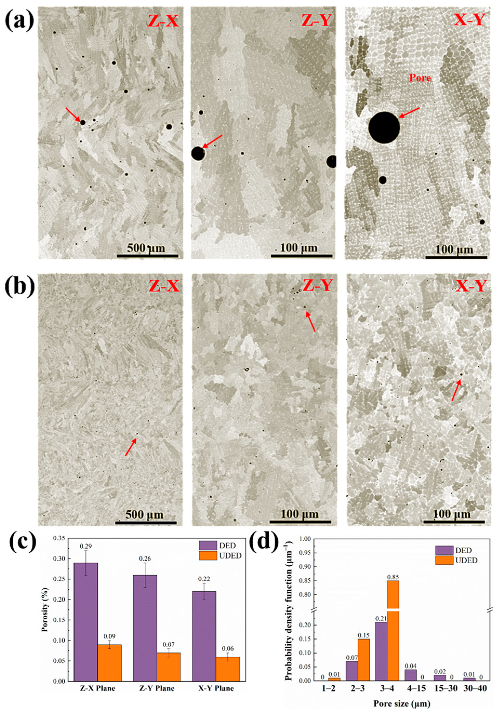
Figure 3a,b present the pore features and porosity analysis results of DED and UDED thin-walled Inconel 718 samples at different cross-sections (Z–X, Z–Y, and X–Y planes, as labeled in Figure 1b). Note that the scale bar in the Z–X plane is 500 μm, and the bars in Z–Y and X–Y planes are 100 μm. As shown in Figure 3a, there were many circular pores formed in the three planes of the DED sample, most of which were between 10 μm and 50 μm in diameter. This indicated that the primary defect in the DED process of Inconel 718 parts is a pore, typically with a diameter less than 50 μm. It has been demonstrated that these spherical pores are formed from trapped gas bubbles that failed to escape before the alloy solidification [29]. In contrast, in the Z–X, Z–Y, and X–Y planes of the UDED sample shown in Figure 3b, the number of pores significantly decreased, and the size was much smaller, approximately a few microns. Figure 3c compares the porosity of different cross-sections on DED and UDED samples. In the DED case, the porosity lay in a range of 0.22–0.29%, while for the UDED sample, it was 0.06–0.09%. Moreover, the pore size distributions of DED and UDED samples are depicted in Figure 3d, where the planes Z–X, Z–Y, and X–Y are not differentiated due to negligible differences between them. It can be seen that the probability density function of pore size for the DED sample indicated a broad distribution with the size ranging from 4 μm to 40 μm and an average value of approximately 12.5 μm, while in the UDED case, it demonstrated an extremely narrow distribution with the size predominantly lying in 3–4 μm and an average value of approximately 3.3 μm. Thus, the ultrasonic vibration decreased the porosity by 71% and the average pore size by 74% for an additive manufacturing thin-walled Inconel 718 component.

3.2. Phase Analysis by XRD

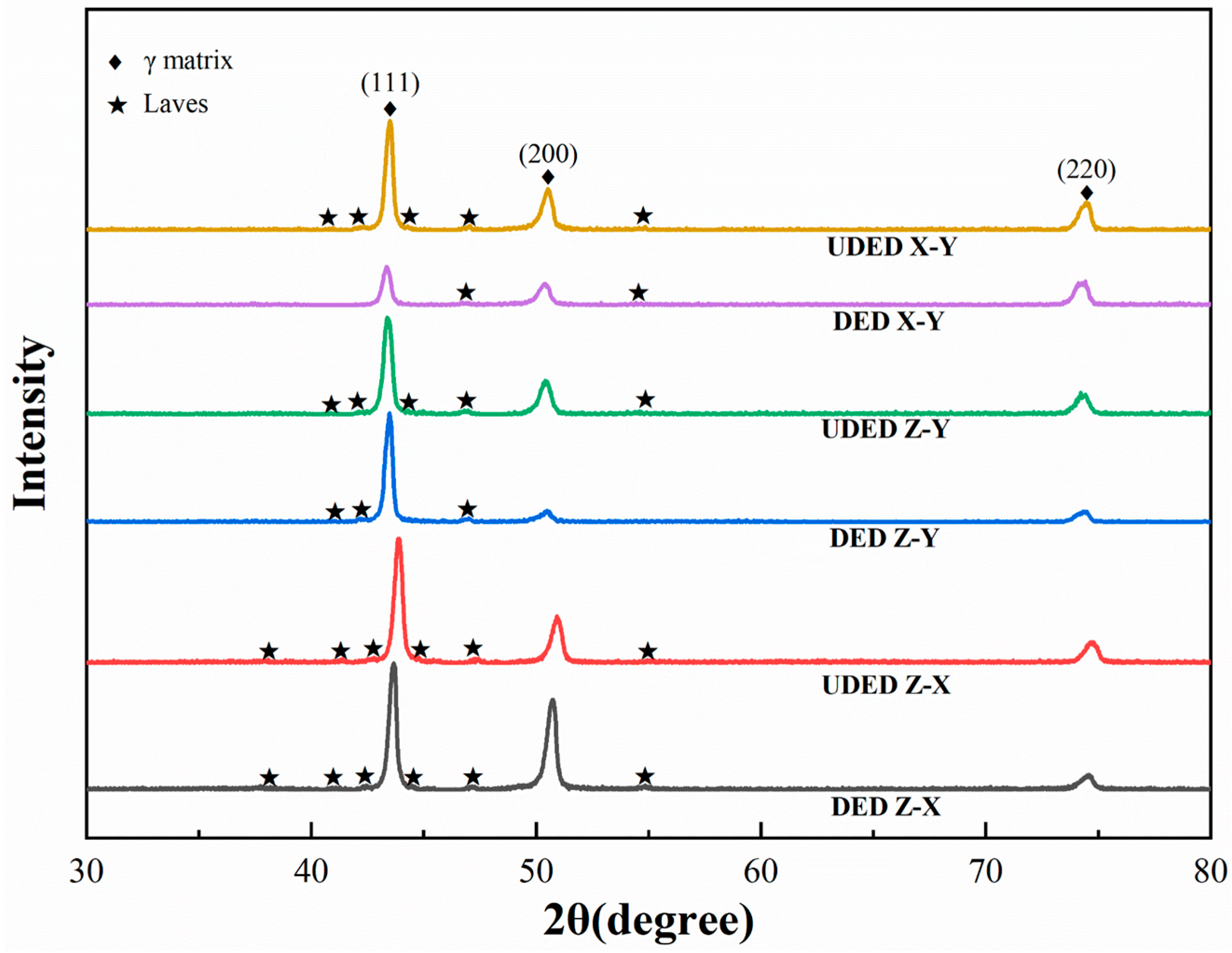
Figure 4 shows the XRD patterns acquired from the middle regions of different cross-sections of DED and UDED thin-walled Inconel 718 samples. The diffraction peaks (111), (200), and (220) of the face-centered cubic γ matrix phase were clearly identified. A comparison between the diffraction profiles revealed significant differences in crystallographic preferred orientation for an identical plane of DED and UDED samples. Moreover, the DED samples exhibited different textures or texture magnitudes between the Z–X, Z–Y, and X–Y planes, whereas the UDED samples showed good consistency across these planes. The crystallographic preferred orientation of the two samples was further analyzed via EBSD in subsequent sections. Furthermore, some weak diffraction peaks corresponding to the Laves phase were also detected in both DED and UDED samples. Additionally, no diffraction peaks of the δ phase or MC carbides were detected, probably due to their low content.

3.3. Laves Phase Morphology and Distribution

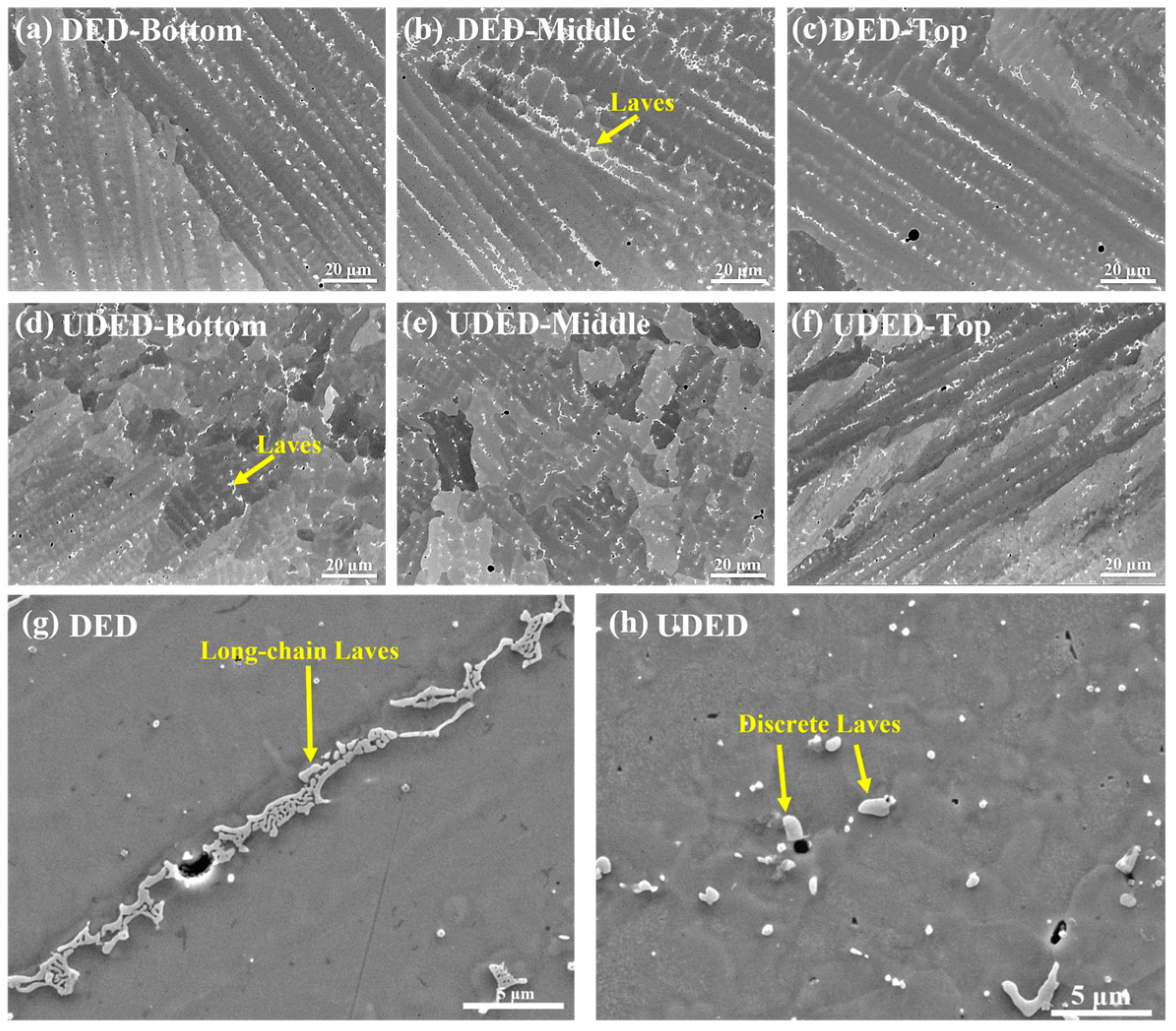
Figure 5 displays the microstructures in the bottom, middle, and top regions (the Z–X planes) of the DED and UDED thin-walled Inconel 718 samples. In this figure, the gray-black areas represent the matrix, while the bright regions (indicated by yellow arrows) surrounding the matrix phase are Laves phases. Figure 5a–c reveal the presence of continuous chain-like Laves phases in all regions of the DED sample. The morphology of the long-chain Laves phase is depicted in Figure 5g, where the phase length ranges from tens to hundreds of microns, significantly larger than the phase cross-section size. Figure 5d–f show that in the bottom and middle regions of the UDED sample, the Laves phases were predominantly discrete, fine, granular, and randomly distributed. The granular Laves phase has a size within a few microns, as shown in Figure 5h. Nevertheless, in the top region of the UDED sample in Figure 5f, a certain number of long-chain Laves phases appeared. Additionally, for DED and UDED samples, the morphology and distribution of Laves phase in the Z–Y and X–Y planes were similar to those in the Z–X planes presented here.

3.4. Chemical Composition

The EDS analysis was performed to compare the chemical compositions of the DED and UDED thin-walled Inconel 718 samples. Figure 6a,b present the EDS mappings of the Z–X planes in DED and UDED samples. The EDS results were summarized in Table 2. It can be seen that the as-deposited Inconel 718 is primarily composed of γ matrix (the locations A and D), Laves phase (the locations B and E), and MC particles including Ti-rich nitrides (the location C) and Nb-rich carbides (the location F).
To investigate the relationship between the elemental micro-segregation and Laves phase morphology, the Nb and Mo contents in the γ matrices (at locations A1 and D1) and the elongated and discrete Laves phases (at locations B1 and E1) were examined, and the results are shown in Figure 6c,d. Specifically, the Nb content in γ matrices was 2.5–5 wt. %, while in Laves phases it reached 15–20 wt. %, significantly higher than the nominal 5.1 wt. % in Inconel 718. The Mo content in γ matrices ranged from 1.5 wt. % to 3 wt. %, while it is 3–4 wt. % in the Laves phase. This indicates weak Mo segregation, which is significantly less pronounced than the Nb segregation due to Mo’s lower diffusion rate and higher density [30]. Moreover, compared to the DED matrix, the UDED one had relatively high Nb and Mo contents, while UDED Laves phase had low Nb and Mo contents. Note that the chemical compositions examined in the Z–Y and X–Y planes were consistent with those in the Z–X planes presented here. Thus, the formation of fine and discrete Laves phases induced by the ultrasonic vibration effectively mitigates the Nb and Mo segregation in the deposited thin-walled Inconel 718 component.

3.5. Matrix Grain Morphology

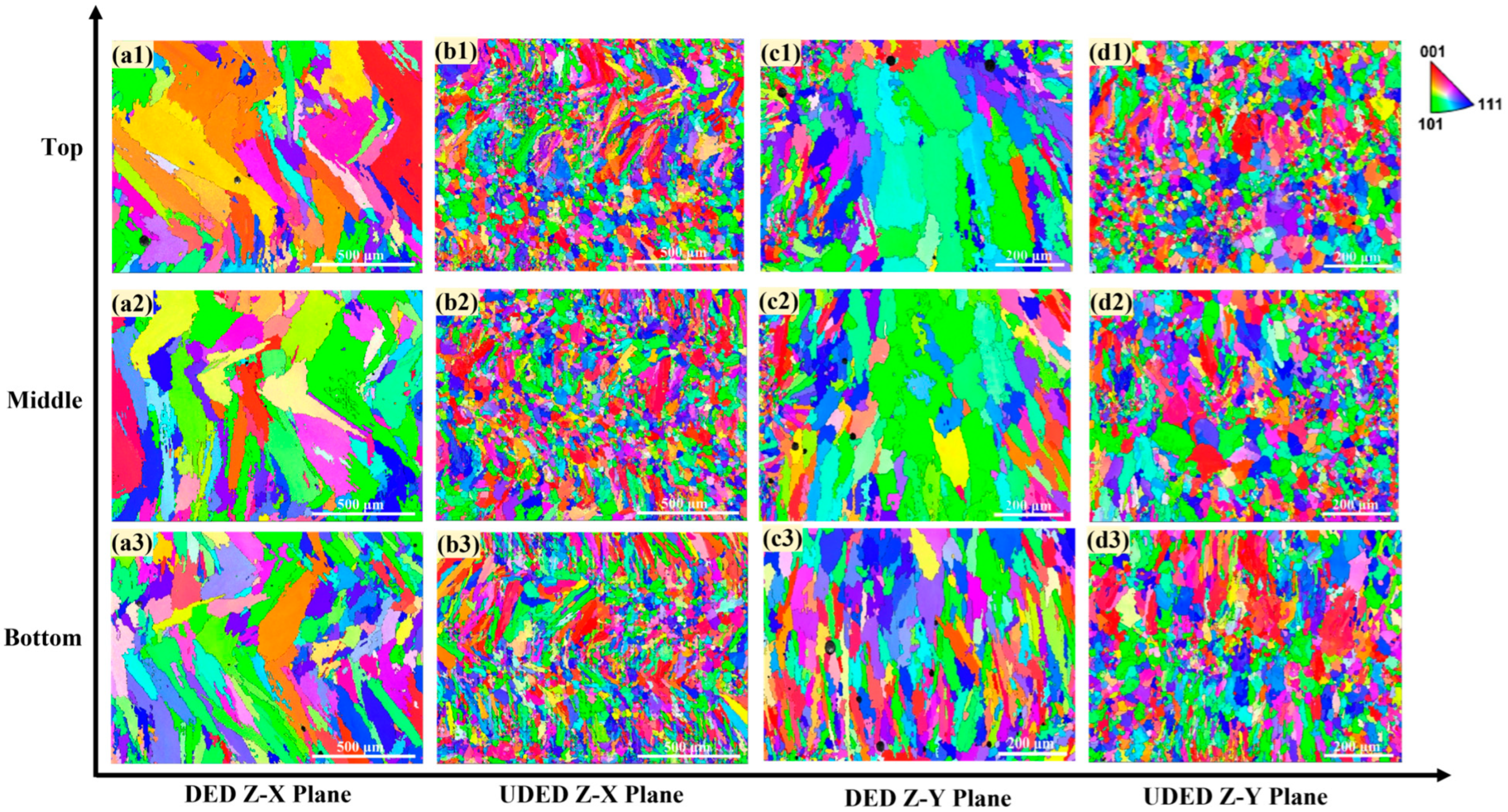
Figure 7 shows the grain morphologies in the Z–X and Z–Y planes (from the bottom to top regions) of the matrices in DED and UDED thin-walled Inconel 718 samples. For the DED sample (Figure 7(a1–a3) for Z–X plane and Figure 7(c1–c3) for Z–Y plane), a significant number of columnar grains grew along the Z direction, although the longitudinal axis of these grains was not completely parallel to the Z direction. In fact, the dendrite growth basically follows the direction of heat flow, which is mainly dependent on the laser scanning path, powder feeding style, and heat conduction of the substrate. In contrast, the UDED sample (Figure 7(b1–b3) for Z–X plane and Figure 7(d1–d3) for Z–Y plane) comprised a significant proportion of equiaxed grains and a smaller proportion of columnar grains, especially these columnar grains having a notably small size compared to those in the DED samples.
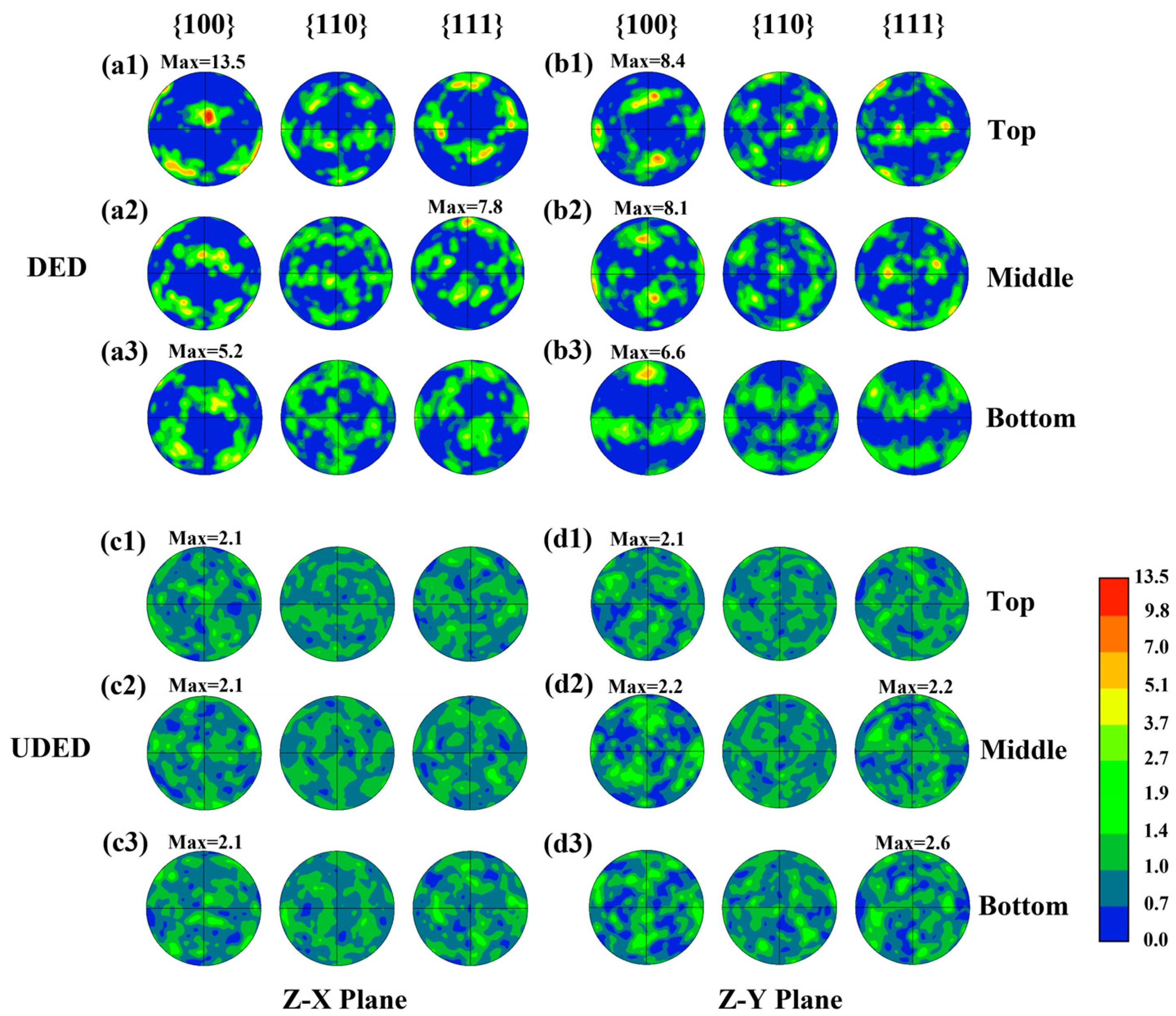
The maximum pole density obtained through the pole figure analysis can reflect the crystallographic preferred orientation of dendritic grains. As shown in Figure 8, in the Z–X plane (Figure 8(a1–a3)), the maximum pole density of the DED thin-walled Inconel 718 sample gradually increased from 5.2 in the bottom region to 13.5 in the top region. Specifically, the bottom and top regions exhibited a strong <001> texture, while the middle region showed a strong <111> texture. In the Z–Y plane (Figure 8(b1–b3)) of the DED sample, the maximum pole density ranged from 6.6 in the bottom region to 8.4 in the top region, always maintaining a strong <001> texture. In contrast, the UDED samples showed consistently low maximum pole densities (values of 2.1–2.6) along the deposited height direction (the Z direction) for both the Z–X plane (Figure 8(c1–c3)) and Z–Y plane (Figure 8(d1–d3)). This result revealed the nearly isotropic microstructures in the UDED sample, and demonstrated that the ultrasonic vibration can effectively homogenize the complex, strongly preferred crystallographic orientation during deposition.
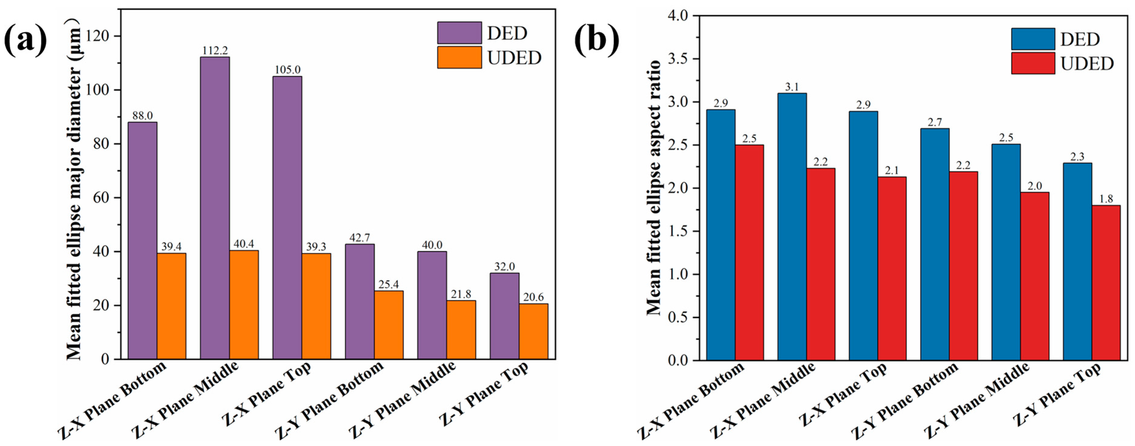
We utilized the fitted average ellipse major axis diameter and aspect ratio (AR) of grains to evaluate the size and shape of the matrix grains in the DED and UDED thin-walled Inconel 718 samples (analyzed from the Z–X and Z–Y planes), and the results are shown in Figure 9. In the Z–X plane, the average fitted ellipse major axis diameters (Figure 9a) for the DED samples were 88 μm, 112.2 μm, and 105 μm in the bottom, middle, and top regions, respectively. With the application of ultrasonic vibration, these values decreased to 39.4 μm, 40.4 μm, and 39.3 μm in the corresponding regions. In the Z–Y plane, the average fitted ellipse major axis diameter decreased with the deposition height for the two samples, especially relatively small values achieved in the UDED case. Moreover, the matrix grain of the DED sample displayed a significant difference in the average ellipse major axis for different planes. In contrast, the matrix grain of the UDED sample exhibited a good consistency in the values of average fitted ellipse major axis diameters for different planes. Furthermore, the variations in the average AR values along the deposition height in the two planes are basically consistent with those of the fitted average ellipse major axis diameter for both DED and UDED samples, as seen in Figure 9b. Also, the matrix grain of the UDED sample had relatively small AR values. Therefore, the ultrasonic vibration not only refines the matrix grains but also alters their morphology, thereby promoting the columnar-to-equiaxed transition (CET).

3.6. Mechanical Properties

3.6.1. Microhardness

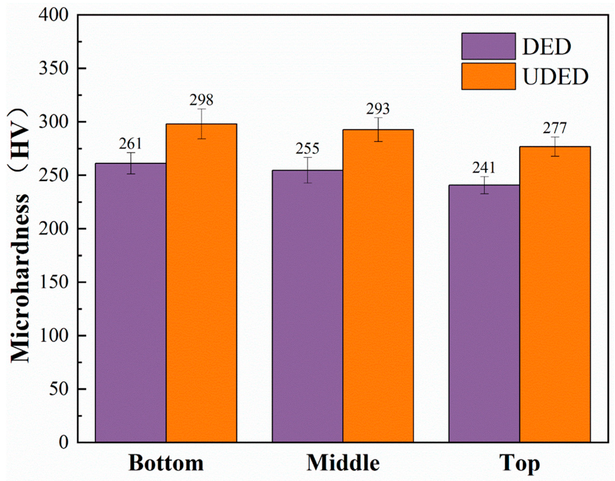
To investigate the effect of ultrasonic vibration on the mechanical properties of deposited thin-walled Inconel 718 samples, we measured the microhardness on the transverse sections (i.e., the Z–X planes). The reported data was the average value of the three repeated measurements, and the distance between two neighboring measurement points was 500 μm. Figure 10 presents the microhardness values in the bottom, middle, and top regions of DED and UDED samples. For the DED sample, the average values were 261 HV (bottom), 255 HV (middle), and 241 HV (top), and in the UDED case, they were 298 HV (bottom), 293 HV (middle), and 277 HV (top). Obviously, as the deposition height increased, the microhardness values for the two samples decreased slightly. Moreover, at an identical height, the UDED samples showed an approximately 15% increase in microhardness compared to the DED samples.

3.6.2. Tensile Property

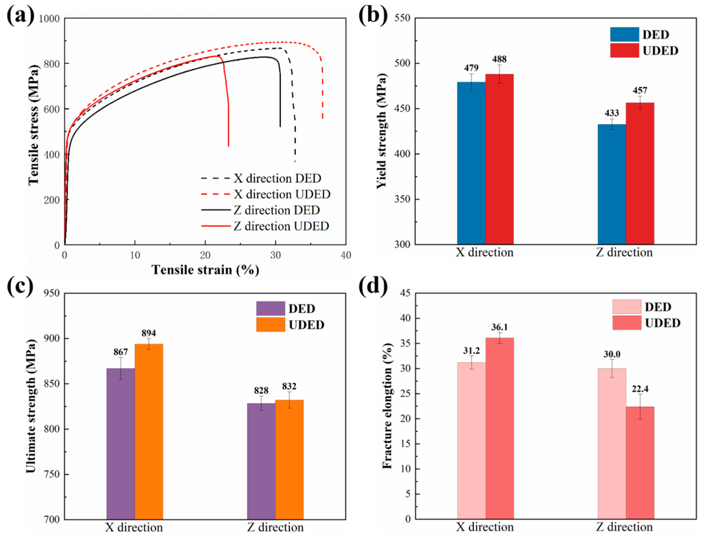
Figure 11 illustrates the typical tensile curves (Figure 11a) of the DED and UDED thin-walled Inconel 718 samples, and the statistical results of YS (Figure 11b), UTS (Figure 11c), and elongation after fracture (EL, as seen in Figure 11d). For samples tested in the X direction, the DED sample exhibited a YS of 479 ± 9 MPa, a UTS of 867 ± 12 MPa, and an EL of 31.2 ± 1.3%. In contrast, the UDED sample had a YS of 488 ± 10 MPa, a UTS of 894 ± 6 MPa, and an EL of 36.1 ± 1.1%. For samples tested in the Z direction, the DED sample displayed a YS of 433 ± 6 MPa, a UTS of 828 ± 8 MPa, and an EL of 30 ± 1.8%, while the UDED sample exhibited a YS of 457 ± 7 MPa, a UTS of 832 ± 9 MPa, and an EL of 22.4 ± 2.5%. It is apparent that the UDED sample showed an enhancement in the strength when deformed along either X or Z directions, and along the X direction, its EL was superior to that of the DED sample, but along the other direction, a decrease in the EL was obtained.

3.6.3. Fracture Morphology

Figure 12 shows the typical fracture morphologies of DED and UDED thin-walled Inconel 718 samples after tensile tests. The fracture surface of the X-direction-tested DED sample exhibited a dendritic trace (indicated by the white dotted lines in Figure 12a), which may be left by the fracture of the columnar matrix grains. Several cavities (indicated by the green arrows in Figure 12b) were observed in dimples, while severe cracking (indicated by the yellow arrows) was formed by the separation of large Laves phases from the γ matrix. For the X-direction-tested UDED sample, its fracture morphology in Figure 12c was similar to that of the DED sample (Figure 12a), but its magnified fracture morphology in Figure 12d displayed densely packed, fine dimples. The observation was consistent with the superior ductility of the X-direction-tested UDED sample (Figure 11a). After the Z-direction tensile test, there are lots of hemispherical cavities (indicated by the white arrows in Figure 12e) on the fracture surface of the DED sample, while a cavity-free morphology can be seen in the UDED sample (Figure 12g). The magnified SEM images in Figure 12f,h indicated a similar ductile fracture morphology for the two samples tested along the Z direction.

4. Discussion

4.1. The Effect of Ultrasonic Vibration on the Microstructure of Inconel 718

In this section, we discussed how ultrasonic vibration optimizes the microstructures of deposited thin-walled Inconel 718 samples. The experimental results in Section 3.1 demonstrated that the ultrasonic vibration significantly reduced the porosity. This reduction can be attributed to the combined effects of acoustic streaming and cavitation induced by the ultrasonic vibration [31]. Acoustic streaming enhances fluid flow and promotes the rapid escape of gas bubbles within the molten pool, while cavitation generates, grows, and collapses microbubbles that either coalesce into large escaping bubbles or fragment to prevent pore formation, collectively reducing porosity.
The XRD analysis in Section 3.2 confirmed that both the γ matrix phase and Laves phase were present in the DED and UDED thin-walled Inconel 718 samples. The identical phase constituent suggested that ultrasonic vibration does not affect the phase transformation mechanism during solidification of Inconel 718. In contrast, the differences in diffraction peak profiles revealed that ultrasonic vibration significantly alters the crystallographic texture of the matrix grains.
The results in Section 3.3 demonstrated that the UDED technology produced fine, discrete Laves phases in thin-walled Inconel 718 samples, contrasting with the continuous chain-like Laves phases produced by the conventional DED manner. Also, the results in Section 3.4 revealed the mitigated Nb and Mo segregation in the UDED sample.
The formation of Laves phases and their morphology are closely associated with the Nb and Mo micro-segregation [32]. During the conventional DED, the rapid cooling rates and high thermal gradients, combined with insufficient elemental diffusion time, commonly lead to solute segregation and the arbitrary growth of Laves phases. However, the ultrasonic vibration can generate mechanical stirring forces, which effectively improve the melt fluidity and homogenize the elemental distribution. This results in the fragmentation of Laves phases into fine, discrete particles. The formed fine Laves phase particles with a high surface area-to-volume ratio have an enhanced dissolution tendency into the γ matrix and surrounding element-rich regions during cooling. This process facilitates the redistribution of solute elements, significantly reducing the concentration of Nb in the dendritic boundary regions [33,34,35,36], thereby mitigating the micro-segregation. It was notable that a certain amount of elongated Laves phases appeared in the top regions of UDED samples. This phenomenon may be attributed to the reduced effect of ultrasonic vibration during the deposition of upper layers [37]. Additionally, as the deposition height increased, the cooling rates basically decreased, thus providing more time for the persistent growth of Laves phases.
The results in Section 3.5 demonstrated that ultrasonic vibration simultaneously refines matrix grains and alters their morphology, promoting CET in deposited thin-walled Inconel 718 samples. During conventional DED, the directional heat flow and large thermal gradients are thought to facilitate the formation of coarse columnar dendrites through layer remelting [38], while the ultrasonic vibration with the mechanical stirring effect might disrupt thermal gradients [39], improve melt homogeneity, and thereby promote the formation of equiaxed grains.
The matrix grain refinement induced by ultrasonic vibrations is attributed to the promoted nucleation. Based on the methodology established by Alexander et al. [40], Lee et al. [41] quantified the additional energy contributed by ultrasonic vibration toward nucleation, and the total free energy change ΔG(r) associated with forming a spherical nucleus of radius r is expressed as
G ( r ) = 4 π r 2 γ + 4 π r 3 3 G v + W u
where, 4πr2γ is the interfacial free energy to create a surface with γ being the surface energy, ΔGv is the volume free energy change, and ΔWu is the additional energy from the ultrasonic vibration.
It can be found that the ΔG(r) has a maximum at
r crit = 2 γ ( G v + W u )
where rcrit is known as the critical nucleus radius, and obviously, it decreases with the addition of ΔWu.
Moreover, the critical free energy barrier ΔGcrit can be determined by minimizing the ΔG(r):
G crit   =   16 π γ 3 3 ( G v   +   W u ) 2
Consequently, the presence of ΔWu can lower the ΔGcrit. Furthermore, the nucleation rate J can be described by an Arrhenius-type expression [42]:
  J   =   Aexp G crit k B T
where, A is the pre-exponential factor, kB is the Boltzmann constant, and T is the temperature. As seen from Equation (4), a reduction in ΔGcrit leads to an increase in J.
Thus, during deposition, the ultrasonic vibration essentially serves as an additional energy resource, which significantly refines the matrix grains by reducing the critical nucleus radius, lowering the critical free energy barrier, and increasing the nucleation rate.
Finally, the results in Section 3.5 demonstrated that UDED significantly altered the preferred orientation of the matrix grains in deposited Inconel 718 thin-walled samples. After ultrasonic treatment, both the Z–X and Z–Y planes showed uniformly low pole densities without height or orientation dependence. This is primarily attributed to synergistic cavitation and acoustic streaming effects. The cavitation effect inevitably generates transient bubbles, whose collapse can produce localized high pressures to effectively break the preferred growth of dendrites [43]. Meanwhile, the Marangoni flow enhanced by acoustic streaming might effectively disperse the nucleation sites and thus randomize the grain growth direction [44]. Additionally, the nearly isotropic microstructures of the UDED sample were related to the ultrasonic-induced dynamic recrystallization [45].

4.2. The Relationship of Microstructure and Mechanical Properties

The UDED thin-walled Inconel 718 sample exhibited a high microhardness (Figure 10), YS and UTS (Figure 11) relative to the conventional DED sample, probably due to the synergistic effects of improved densification, dispersion strengthening from fine, discrete Laves phases, solid solution strengthening from the elements Nb and Mo, and matrix-grain refinement (grain boundary strengthening). Moreover, the mechanical properties of Inconel 718 might also be related to the dislocations [46], stacking faults [47], and textures [48] in the deposited microstructures.
Firstly, the deposited pores, especially with a large size, would deteriorate the mechanical properties of the thin-walled Inconel 718 sample. During deformation, such a type of structural defect readily generates localized stress concentrations at its boundaries, while serving as the preferential sites for microcrack initiation [49]. In this study, the porosity reduction by UDED was considered to effectively relieve the pore-dependent stress concentration and prevent the relevant crack initiation, thus enhancing the YS and microhardness, as evidenced by Zhou et al. [50] through combined strain modeling and fractographic analysis. On the other hand, the porosity reduction basically decreases the density of weak pore boundaries/interfaces where the formed cracks propagate easily. And it densified Inconel 718 alloys to effectively delay the plastic instability (i.e., necking) during deformation [51,52]. Thus, the UDED sample with a low porosity exhibited a high UTS.
Secondly, the Laves phase is intrinsically brittle and possesses limited ductility [28]. During deformation, its large-size, chain-like morphology could impede its movement along with the matrix. Moreover, the incoherent interfaces between the Laves phase and the matrix tend to promote stress concentration and initiate microcracks [28]. As a result, the as-deposited morphology of Laves phases is most likely detrimental to the mechanical properties of the DED Inconel 718 sample. With the ultrasonic treatment yielding fine, discrete Laves phase particles in the UDED sample, these dispersed Laves particles can strengthen Inconel 718 predominantly through the Orowan mechanism [53], wherein dislocations bypass the particles. This process increases the critical stress required for dislocation glide, thereby effectively enhancing both YS and microhardness of the UDED sample. On the other hand, during plastic deformation, these fine and discrete particles effectively hinder dislocation motion, promoting extensive dislocation accumulation, entanglement, and storage [54]. As a result, the UTS of the UDED sample is significantly improved.
Moreover, the ultrasonic vibration enables more Nb and Mo to dissolve into the matrix and effectively mitigates the micro-segregation. These dissolved atoms with a large diameter would introduce substantial lattice distortions or mismatches within the matrix, generating strong elastic stress fields [55]. Through resisting the initial dislocation glide, the incorporation of Nb and Mo atoms could enhance the microhardness and YS of the UDED Inconel 718 sample, and it might contribute to the high UTS by promoting the dislocation accumulation.
Furthermore, the matrix grain refinement plays a critical role in the enhancement of the strength of the UDED Inconel 718 sample. This can be explained by the Hall–Petch relationship [56]:
σ y   =   σ 0   +   k d
where, σy is the YS, σ0 is the resistance to dislocation motion within the grain, k is a material constant, and d is the grain size. Obviously, the reduction in grain size can increase the strength and hardness of polycrystalline metals or alloys because the grain boundary acts as a barrier to dislocation movement.
Regarding the ductility of deposited Inconel 718 samples, the ultrasonic vibration significantly improved EL in the X direction, primarily owing to the synergistic effects of multiple microstructural modifications. Specifically, the reduction in porosity, enhanced elemental homogeneity, and fragmentation of Laves phases collectively helped mitigate the stress concentration and delay the microcrack initiation for deforming the UDED Inconel 718 [57]. Additionally, the refinement of matrix grains into an equiaxed morphology could promote stress relaxation and facilitate more uniform plastic deformation of the UDED Inconel 718 sample.
Nevertheless, in the Z direction, the EL of the UDED sample was lower than that of the DED sample, which may be associated with the interlayer bonding quality, dislocation motion, and crystallographic orientation. Firstly, the ultrasonic vibration significantly refined the matrix grains, but it disrupted the continuity of columnar grains across layers along the build direction. Thus, the UDED sample—which lacked interconnected coarse columnar grains spanning the interlayer interfaces—might exhibit reduced ductility along the deposition. Secondly, during tensile testing along the Z direction, the dislocations nucleate and propagate within the fine equiaxed grains of the UDED sample. However, they will be rapidly impeded by the grain boundaries or interlayer interfaces, leading to significant dislocation pile-ups and substantial stress concentration [58]. As this stress concentration cannot be effectively relieved by the dislocation slip across these boundaries/interfaces, the microcracks may preferentially initiate and propagate along these boundaries/interfaces [59], and consequently, the UDED sample macroscopically exhibited a reduction in the elongation along the Z direction. Additionally, for the nickel-based Inconel 718 alloy with a face-centered cubic structure studied here, the predominant dislocation slip system is {111}<110> [60]. When the tensile stress is applied along the Z direction, the DED sample, which had a strong <001> texture nearly parallel to the Z direction (Figure 7 and Figure 8a,b), is thought to contain multiple slip systems with high Schmid factors. This will facilitate the long-range dislocation slip within its coarse grains [61]. However, for the UDED sample without obvious texture, its grains have the slip systems with relatively low Schmid factors, thus resulting in relatively high strengths but reduced ductility.

5. Conclusions

This study focused on the influence of ultrasonic vibration on the microstructure and mechanical properties of thin-walled Inconel 718 components. The main conclusions were as follows:
By enhancing molten pool fluidity, the ultrasonic vibration reduced the porosity by approximately 71% and the average pore size by 74% in deposited Inconel 718 components through mechanisms such as facilitating microbubble coalescence, promoting gas bubble escape, and fragmenting existing pores.
The ultrasonic vibration significantly modified the microstructures of Inconel 718 in multiple ways: it eliminated the matrix texture from a complex, strongly preferred orientation to a nearly isotropic state; promoted the columnar-to-equiaxed transition; refined the matrix grains; broke down the continuous chain-like Laves phase into fine discrete particles, and mitigated Nb and Mo segregation.
The UDED thin-walled Inconel 718 sample exhibited high hardness and strength relative to the conventional DED counterpart because of the structural densification, dispersion strengthening, solid solution strengthening, and matrix-grain refinement. The ultrasonic vibration enhanced the elongation of Inconel 718 in the direction perpendicular to the build direction, yet decreased it along the build direction. This discrepancy in ductility is possibly associated with the interlayer bonding quality, dislocation motion, and crystallographic orientation.
This comparative study preliminarily demonstrates the potential of UDED technology in tailoring the microstructure and mechanical properties of thin-walled Inconel 718 alloys. In the future, we will fabricate thin-walled Inconel 718 components under different ultrasonic vibration parameters and perform comprehensive mechanical property evaluation—particularly high-temperature tensile and fatigue tests—to further elucidate the superiority of ultrasonic vibration in enhancing the manufacturing quality of Inconel 718.

Author Contributions

Conceptualization, B.P., X.Z. and F.B.; methodology, B.P., M.Z. and Z.C.; investigation, B.P. and Z.C.; formal analysis, X.Z. and M.Z.; writing—original draft preparation, B.P.; writing—review and editing, B.P., Z.C. and X.C.; supervision, Z.C. and X.C. All authors have read and agreed to the published version of the manuscript.

Funding

This research received no external funding.

Data Availability Statement

The data are available from the corresponding authors on reasonable request.

Conflicts of Interest

Author Fahai Ba was employed by the company Shanghai Research Institute of Materials Co., Ltd. The remaining authors declare that the research was conducted in the absence of any commercial or financial relationships that could be construed as a potential conflict of interest.

References

  1. Svetlizky, D.; Das, M.; Zheng, B.; Vyatskikh, A.L.; Bose, S.; Bandyopadhyay, A.; Schoenung, J.M.; Lavernia, E.J.; Eliaz, N. Directed energy deposition (DED) additive manufacturing: Physical characteristics, defects, challenges and applications. Mater. Today 2021, 49, 271–295. [Google Scholar] [CrossRef]
  2. Wang, Y.; Hu, K.; Li, W.; Wang, L. Prediction of melt pool width and layer height for Laser Directed Energy Deposition enabled by physics-driven temporal convolutional network. J. Manuf. Syst. 2023, 69, 1–17. [Google Scholar] [CrossRef]
  3. Sommer, N.; Bauer, A.; Kahlmeyer, M.; Wegener, T.; Degener, S.; Liehr, A.; Bolender, A.; Vollmer, M.; Holz, H.; Zeiler, S.; et al. High-throughput alloy development using advanced characterization techniques during directed energy deposition additive manufacturing. Adv. Eng. Mater. 2023, 25, 2300030. [Google Scholar] [CrossRef]
  4. Kelly, J.P.; Elmer, J.W.; Ryerson, F.J.; Lee, J.R.I.; Haslam, J.J. Directed energy deposition additive manufacturing of functionally graded Al-W composites. Addit. Manuf. 2021, 39, 101845. [Google Scholar] [CrossRef]
  5. Shinjo, J.; Panwisawas, C. Chemical species mixing during direct energy deposition of bimetallic systems using titanium and dissimilar refractory metals for repair and biomedical applications. Addit. Manuf. 2022, 51, 102654. [Google Scholar] [CrossRef]
  6. Saboori, A.; Aversa, A.; Marchese, G.; Biamino, S.; Lombardi, M.; Fino, P. Microstructure and Mechanical Properties of AISI 316L Produced by Directed Energy Deposition-Based Additive Manufacturing: A Review. Appl. Sci. 2020, 10, 3310. [Google Scholar] [CrossRef]
  7. Vashishtha, H.; Kumar, D.; Kim, Y.S.; Lee, S.Y.; Huang, E.W.; Jain, J. Effects of hot isostatic processing and hot rolling on direct energy deposited CoCrNi medium entropy alloy–Microstructural heterogeneity, wear behaviour and corrosion characteristics. Mater. Charact. 2023, 205, 113304. [Google Scholar] [CrossRef]
  8. Shalnova, S.A.; Kuzminova, Y.O.; Evlashin, S.A.; Klimova-Korsmik, O.G.; Vildanov, A.M.; Shibalova, A.A.; Turichin, G.A. Effect of recycled powder content on the structure and mechanical properties of Ti-6Al-4V alloy produced by direct energy deposition. J. Alloys Compd. 2022, 893, 162264. [Google Scholar] [CrossRef]
  9. Pasang, T.; Budiman, A.S.; Wang, J.C.; Jiang, C.P.; Boyer, R.; Williams, J.; Misiolek, W.Z. Additive manufacturing of titanium alloys–Enabling re-manufacturing of aerospace and biomedical components. Microelectron. Eng. 2023, 270, 111935. [Google Scholar] [CrossRef]
  10. Di, T.; Zhao, Y.; Song, C.; Hu, Y.; Ma, G.; Wang, Z.; Niu, F.; Wu, D. Mechanism of grain refinement and mechanical property enhancement of Ti-45Al-8Nb alloy by directed laser deposition. J. Alloys Compd. 2023, 939, 168729. [Google Scholar] [CrossRef]
  11. Ma, W.; Xie, Y.; Chen, C.; Fukanuma, H.; Wang, J.; Ren, Z.; Huang, R. Microstructural and mechanical properties of high-performance Inconel 718 alloy by cold spraying. J. Alloys Compd. 2019, 792, 456–467. [Google Scholar] [CrossRef]
  12. Yin, X.; Zhao, S.; Liu, Y.; Zhai, Y.; Li, X.; Geng, D.; Zhang, D. Evaluation of profile accuracy and surface integrity for Inconel 718 blade machined by ultrasonic peening milling. J. Manuf. Process. 2023, 104, 150–163. [Google Scholar] [CrossRef]
  13. Calandri, M.; Yin, S.; Aldwell, B.; Calignano, F.; Lupoi, R.; Ugues, D. Texture and microstructural features at different length scales in Inconel 718 produced by selective laser melting. Materials 2019, 12, 1293. [Google Scholar] [CrossRef] [PubMed]
  14. Zhang, J.Y.; Xu, B.; Tariq, N.H.; Sun, M.Y.; Li, D.Z.; Li, Y.Y. An innovative approach for grain refinement in Ni-based superalloys: Modification in the classical delta process through γ″ pre-aging treatment. J. Alloys Compd. 2020, 818, 152827. [Google Scholar] [CrossRef]
  15. Zhou, S.; Liu, Z.; Yang, G.; Li, X.; Wang, J.; Guo, X.; Wang, X. Heterostructure microstructure and laves phase evolution mechanisms during inter-layer hammering hybrid directed energy deposition (DED) process. Mater. Sci. Eng. A 2023, 886, 145668. [Google Scholar] [CrossRef]
  16. Alfred, S.O.; Amiri, M. High-temperature fatigue of additively manufactured Inconel 718: A short review. J. Eng. Mater. Technol. 2025, 147, 010801. [Google Scholar] [CrossRef]
  17. Ono, Y.; Yuri, T.; Sumiyoshi, H.; Takeuchi, E.; Matsuoka, S.; Ogata, T. High-cycle fatigue properties at cryogenic temperatures in Inconel 718 nickel-based superalloy. Mater. Trans. 2004, 45, 342–345. [Google Scholar] [CrossRef]
  18. Li, W.B.; Pang, J.C.; Zhang, H.; Li, S.X.; Zhang, Z.F. The high-cycle fatigue properties of selective laser melted Inconel 718 at room and elevated temperatures. Mater. Sci. Eng. A 2022, 836, 142716. [Google Scholar] [CrossRef]
  19. Wild, G.; Pollock, L.; Abdelwahab, A.K.; Murray, J. The need for aerospace structural health monitoring: A review of aircraft fatigue accidents. Int. J. Progn. Health Manag. 2021, 12, 1–16. [Google Scholar] [CrossRef]
  20. Yang, Z.; Zhu, L.; Dun, Y.; Ning, J.; Wang, S.; Xue, P.; Xu, P.; Yu, M.; Yan, B.; Xin, B. In-situ monitoring of the melt pool dynamics in ultrasound-assisted metal 3D printing using machine learning. Virtual Phys. Prototyp. 2023, 18, e2251453. [Google Scholar] [CrossRef]
  21. Wang, Z.; Jiang, F.; Guo, C.; Xing, X.; Yang, Z.; Li, H.; Liu, C.; Xu, D.; Jiang, G.; Konovalov, S. Effects of ultrasonic vibration on microstructure and mechanical properties of 1Cr12Ni3MoVN alloy fabricated by directed energy deposition. Ultrasonics 2023, 132, 106989. [Google Scholar] [CrossRef]
  22. Gorunov, A.I. Additive manufacturing of Ti6Al4V parts using ultrasonic assisted direct energy deposition. J. Manuf. Process. 2020, 59, 545–556. [Google Scholar] [CrossRef]
  23. Todaro, C.J.; Easton, M.A.; Qiu, D.; Brandt, M.; StJohn, D.H.; Qian, M. Grain refinement of stainless steel in ultrasound-assisted additive manufacturing. Addit. Manuf. 2021, 37, 101632. [Google Scholar] [CrossRef]
  24. Ning, F.; Hu, Y.; Liu, Z.; Wang, X.; Li, Y.; Cong, W. Ultrasonic vibration-assisted laser engineered net shaping of inconel 718 parts: Microstructural and mechanical characterization. J. Manuf. Sci. Eng. 2018, 140, 061012. [Google Scholar] [CrossRef]
  25. Xu, H.; Jian, X.; Meek, T.T.; Han, Q. Degassing of molten aluminum A356 alloy using ultrasonic vibration. Mater. Lett. 2004, 58, 3669–3673. [Google Scholar] [CrossRef]
  26. Cong, W.; Ning, F. A fundamental investigation on ultrasonic vibration-assisted laser engineered net shaping of stainless steel. Int. J. Mach. Tools Manuf. 2017, 121, 61–69. [Google Scholar] [CrossRef]
  27. Yang, Z.; Zhu, L.; Wang, S.; Ning, J.; Dun, Y.; Meng, G.; Xue, P.; Xu, P.; Xin, B. Effects of ultrasound on multilayer forming mechanism of Inconel 718 in directed energy deposition. Addit. Manuf. 2021, 48, 102462. [Google Scholar] [CrossRef]
  28. Xu, L.; Chai, Z.; Zhang, X.; Peng, B.; Zhou, W.; Chen, X. A new approach to improve strength and ductility of laser powder deposited Inconel 718 thin-wall structure. Mater. Sci. Eng. A 2022, 855, 143871. [Google Scholar] [CrossRef]
  29. Sohn, H.; Liu, P.; Yoon, H.; Yi, K.; Yang, L.; Kim, S. Real-time porosity reduction during metal directed energy deposition using a pulse laser. J. Mater. Sci. Technol. 2022, 116, 214–223. [Google Scholar] [CrossRef]
  30. Manikandan, S.G.K.; Sivakumar, D.; Prasad Rao, K.; Kamaraj, M. Effect of weld cooling rate on Laves phase formation in Inconel 718 fusion zone. J. Mater. Process. Technol. 2014, 214, 358–364. [Google Scholar] [CrossRef]
  31. Ning, F.; Hu, Y.; Cong, W. Microstructure and mechanical property of TiB reinforced Ti matrix composites fabricated by ultrasonic vibration-assisted laser engineered net shaping. Rapid Prototyp. J. 2018, 25, 581–591. [Google Scholar] [CrossRef]
  32. Xiao, W.; Xu, Y.; Xiao, H.; Li, S.; Song, L. Investigation of the Nb element segregation for laser additive manufacturing of nickel-based superalloys. Int. J. Heat Mass Transf. 2021, 180, 121800. [Google Scholar] [CrossRef]
  33. Wang, H.; Hu, Y.; Ning, F.; Cong, W. Ultrasonic vibration-assisted laser engineered net shaping of Inconel 718 parts: Effects of ultrasonic frequency on microstructural and mechanical properties. J. Mater. Process. Technol. 2020, 276, 116395. [Google Scholar] [CrossRef]
  34. Xiao, H.; Xie, P.; Cheng, M.; Song, L. Enhancing mechanical properties of quasi-continuous-wave laser additive manufac-tured Inconel 718 through controlling the niobium-rich precipitates. Addit. Manuf. 2020, 34, 101278. [Google Scholar]
  35. Chen, Y.; Guo, Y.; Xu, M.; Ma, C.; Zhang, Q.; Wang, L.; Yao, J.; Li, Z. Study on the element segregation and Laves phase formation in the laser metal deposited IN718 superalloy by flat top laser and Gaussian distribution laser. Mater. Sci. Eng. A 2019, 754, 339–347. [Google Scholar] [CrossRef]
  36. Liu, F.; Cheng, H.; Yu, X.; Yang, G.; Huang, C.; Lin, X.; Chen, J. Control of microstructure and mechanical properties of laser solid formed Inconel 718 superalloy by electromagnetic stirring. Opt. Laser Technol. 2018, 99, 342–350. [Google Scholar] [CrossRef]
  37. Endo, Y.; Kimura, Y.; Saka, M. Ultrasonic-induced morphological change of micro/nanodeposits and current change in electrochemical migration. MRS Commun. 2019, 9, 1331–1334. [Google Scholar] [CrossRef]
  38. Farshidianfar, M.H.; Khajepour, A.; Gerlich, A.P. Effect of real-time cooling rate on microstructure in Laser Additive Manufacturing. J. Mater. Process. Technol. 2016, 231, 468–478. [Google Scholar] [CrossRef]
  39. Schmitt, M.; Stark, H. Marangoni flow at droplet interfaces: Three-dimensional solution and applications. Phys. Fluids 2016, 28, 012106. [Google Scholar] [CrossRef]
  40. Alexander, A.J.; Camp, P.J. Single pulse, single crystal laser-induced nucleation of potassium chloride. Cryst. Growth Des. 2009, 9, 958–963. [Google Scholar] [CrossRef]
  41. Lee, J.; Yang, S. Antisolvent sonocrystallisation of sodium chloride and the evaluation of the ultrasound energy using modified classical nucleation theory. Crystals 2018, 8, 320. [Google Scholar] [CrossRef]
  42. Mullin, J.W. Crystallization, 4th ed.; Butterworth-Heinemann: Oxford, UK, 2011; p. 594. [Google Scholar]
  43. Wang, F.; Eskin, D.; Mi, J.; Connolley, T.; Lindsay, J.; Mounib, M. A refining mechanism of primary Al3Ti intermetallic particles by ultrasonic treatment in the liquid state. Acta Mater. 2016, 116, 354–363. [Google Scholar] [CrossRef]
  44. Virone, C.; Kramer, H.J.M.; van Rosmalen, G.M.; Stoop, A.H.; Bakker, T.W. Primary nucleation induced by ultrasonic cavitation. J. Cryst. Growth 2006, 294, 9–15. [Google Scholar] [CrossRef]
  45. Sui, S.; Chen, J.; Ming, X.; Zhang, S.; Lin, X.; Huang, W. The failure mechanism of 50% laser additive manufactured Inconel 718 and the deformation behavior of Laves phases during a tensile process. Int. J. Adv. Manuf. Technol. 2017, 91, 2733–2740. [Google Scholar] [CrossRef]
  46. He, M.L.; Cao, H.L.; Liu, Q.; Yi, J.; Ni, Y.; Wang, S. Evolution of dislocation cellular pattern in Inconel 718 alloy fabricated by laser powder-bed fusion. Addit. Manuf. 2022, 55, 102839. [Google Scholar] [CrossRef]
  47. McAllister, D.; Lv, D.; Feng, L.; Deutchman, H.; Wessman, A.; Wang, Y.; Mills, M.J. Characterization and modeling of deformation mechanisms in Ni-base superalloy 718. In Proceedings of the 9th International Symposium on Superalloy 718 & Derivatives, Pittsburgh, PA, USA, 3–6 June 2018; Springer: Cham, Switzerland, 2018; pp. 319–338. [Google Scholar]
  48. Bean, G.E.; McLouth, T.D.; Witkin, D.B.; Sitzman, S.D.; Adams, P.M.; Zaldivar, R.J. Build orientation effects on texture and mechanical properties of selective laser melting Inconel 718. J. Mater. Eng. Perform. 2019, 28, 1942–1949. [Google Scholar] [CrossRef]
  49. Sumi, Y. Stress Concentration Problems. In Mathematical and Computational Analyses of Cracking Formation; Springer: Tokyo, Japan, 2014; pp. 17–30. [Google Scholar]
  50. Zhou, B.; Meng, D.H.; Wu, D.; Tang, J.F.; Chen, R.S.; Li, P.J.; Han, E.H. Characterization of porosity and its effect on the tensile properties of Mg-6Gd-3Y-0.5Zr alloy. Mater. Charact. 2019, 152, 204–212. [Google Scholar] [CrossRef]
  51. Lee, C.D.; Shin, K.S. Effect of microporosity on the tensile properties of AZ91 magnesium alloy. Acta Mater. 2007, 55, 4293–4303. [Google Scholar] [CrossRef]
  52. Lee, C.D. Effects of microporosity on tensile properties of A356 aluminum alloy. Mater. Sci. Eng. A 2007, 464, 249–254. [Google Scholar] [CrossRef]
  53. Orowan, E. Fracture and strength of solids. Rep. Prog. Phys. 1949, 12, 185. [Google Scholar] [CrossRef]
  54. Gomez-Ramirez, R.; Pound, G.M. Nucleation of a second solid phase along dislocations. Metall. Trans. 1973, 4, 1563–1570. [Google Scholar] [CrossRef]
  55. Gunaydin, K.; Gülcan, O. Distortion and dimensional deviation of Inconel 718 auxetic structures produced by DMLM. Addit. Manuf. Technol. 2021, 1, 563. [Google Scholar]
  56. Hall, E.O. The deformation and ageing of mild steel: III discussion of results. Proc. Phys. Soc. B 1951, 64, 747. [Google Scholar] [CrossRef]
  57. Hasani, N.; Dharmendra, C.; Sanjari, M.; Fazeli, F.; Amirkhiz, B.S.; Pirgazi, H.; Janaki Ram, G.D.; Mohammadi, M. Laser powder bed fused Inconel 718 in stress-relieved and solution heat-treated conditions. Mater. Charact. 2021, 181, 111499. [Google Scholar] [CrossRef]
  58. Tekumalla, S.; Seita, M.; Zaefferer, S. Delineating dislocation structures and residual stresses in additively manufactured alloys. Acta Mater. 2024, 262, 119413. [Google Scholar] [CrossRef]
  59. Di, O.; Zhang, C.; Chen, R.; Li, N.; Chan, K.C.; Liu, L. The microcrack inhibition and mechanical properties of an in-situ synthesized refractory high-entropy alloy fabricated by additive manufacturing. Mater. Sci. Eng. A 2024, 913, 147071. [Google Scholar]
  60. Gerold, V.; Karnthaler, H.P. On the origin of planar slip in fcc alloys. Acta Metall. 1989, 37, 2177–2183. [Google Scholar] [CrossRef]
  61. Kad, B.K.; Schoenfeld, S.E.; Asaro, R.J.; McKamey, C.G.; Sikka, V.K. Deformation textures in Fe3Al alloys: An assessment of dominant slip system activity in the 900–1325 K temperature range of hot working. Acta Mater. 1997, 45, 1333–1350. [Google Scholar] [CrossRef]
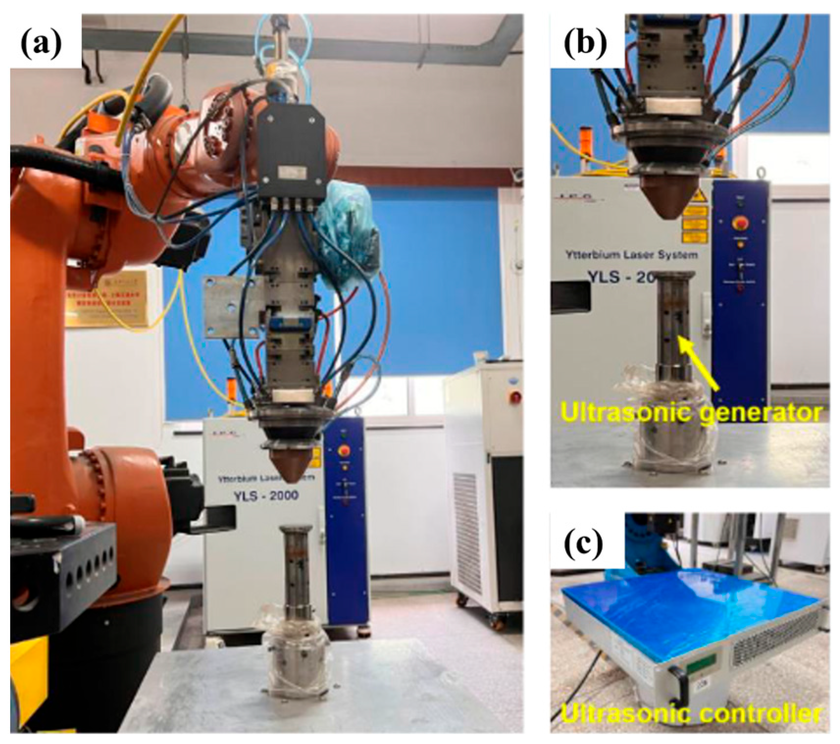
Figure 1. Overview of the experimental setup: (a) DED system, (b) ultrasonic generator, and (c) ultrasonic controller.
Crystals 15 00815 g001
Figure 2. (a) The schematic diagram of the deposited thin-walled Inconel 718 samples, and (b) the sample dimensions for tensile tests.
Crystals 15 00815 g002
Figure 3. The pore analysis of the DED and UDED thin-walled Inconel 718 samples: (a) morphology observation of DED sample, (b) morphology observation of UDED sample, (c) porosity comparison, and (d) probability density function of the pore size.
Crystals 15 00815 g003
Figure 4. XRD patterns of DED and UDED thin-walled Inconel 718 samples.
Crystals 15 00815 g004
Figure 5. Morphologies of Laves phases in (ac,g) DED and (df,h) UDED thin-walled Inconel 718 samples (the Z–X planes): (a,d) the bottom regions, (b,e) the middle regions, (c,f) the top regions, and (g,h) the amplified morphologies.
Crystals 15 00815 g005
Figure 6. Chemical composition analysis of DED and UDED thin-walled Inconel 718 samples (the Z–X planes): (a) EDS mapping of DED sample, (b) EDS mapping of UDED sample, and comparisons of (c) the Nb content and (d) the Mo content in the γ matrix and Laves phase.
Crystals 15 00815 g006
Figure 7. The grain morphologies of the bottom, middle, and top regions in (a1a3,c1c3) DED and (b1b3,d1d3) UDED thin-walled Inconel 718 samples: (a1a3,b1b3) Z–X plane, and (c1c3,d1d3) Z–Y plane.
Crystals 15 00815 g007
Figure 8. The pole figures of the bottom, middle, and top regions in DED and UDED thin-walled Inconel 718 samples: (a1a3) Z–X plane for DED, (b1b3) Z–Y plane for DED, (c1c3) Z–X plane for UDED, and (d1d3) Z–Y plane for UDED.
Crystals 15 00815 g008
Figure 9. Matrix grain size and shape characteristics of DED and UDED thin-walled Inconel 718 samples: (a) mean fitted ellipse major diameter, and (b) mean fitted ellipse aspect ratio.
Crystals 15 00815 g009
Figure 10. Average microhardness of the DED and UDED thin-walled Inconel 718 samples.
Crystals 15 00815 g010
Figure 11. Tensile properties of DED and UDED thin-walled Inconel 718 samples: (a) stress–strain curve, (b) YS, (c) UTS, (d) EL.
Crystals 15 00815 g011
Figure 12. Tensile fracture morphologies of DED and UDED thin-walled Inconel 718 samples: (a,b) DED X direction, (c,d) UDED X direction, (e,f) DED Z direction, (g,h) UDED Z direction.
Crystals 15 00815 g012
Table 1. Chemical compositions of Inconel 718 substrate and Inconel 718 powder (wt. %).
ElementsCrNbMoAlTiMnSiCFeNi
Inconel 718 substrate17.855.183.050.520.950.100.200.0319.79Bal.
Inconel 718 powder19.795.132.950.521.070.010.040.0317.45Bal.
Table 2. The chemical compositions of typical phases in as-deposited samples (wt. %).
PositionCOAlTiCrFeCoNiNbMo
A (Matrix)4.42.72.61.218.318.40.246.53.22.5
B (Laves)4.60.70.41.615.5150.14513.53.6
C (MC)5.91.61.55.316.515.80.139.311.82.2
D (Matrix)6.610.60.918.3190.146.74.32.5
E (Laves)5.50.60.501.516.516.40.146.89.13
F (MC)8.51.60.73.81413.50.138.316.92.6
Disclaimer/Publisher’s Note: The statements, opinions and data contained in all publications are solely those of the individual author(s) and contributor(s) and not of MDPI and/or the editor(s). MDPI and/or the editor(s) disclaim responsibility for any injury to people or property resulting from any ideas, methods, instructions or products referred to in the content.