Review

A Critical Review on Friction Stir Spot Welding of Aluminium Alloys: Tool, Mechanical, and Micro-Structural Characteristics

1
Programme of Mechanical Engineering, Assam down town University, Guwahati 781026, India
2
Department of Mechanical Engineering, North Eastern Regional Institute of Science and Technology, Itanagar 791109, India
3
Chitkara Centre for Research and Development, Chitkara University, Rajpura 174103, India
4
Industrial Engineering Department, College of Engineering, Imam Mohammad Ibn Saud Islamic University (IMSIU), Riyadh 11432, Saudi Arabia
5
Department of Mechanical Engineering, National Institute of Technical Teachers’ Training and Research, Kolkata 700106, India
6
Deanship of Scientific Research, Imam Mohammad Ibn Saud Islamic University (IMSIU), Riyadh 11432, Saudi Arabia
7
Department of Mechanical Engineering, C. V. Raman Global University, Bhubaneswar 752054, India
*
Authors to whom correspondence should be addressed.
Crystals 2025, 15(9), 755; https://doi.org/10.3390/cryst15090755
Submission received: 11 July 2025 / Revised: 9 August 2025 / Accepted: 18 August 2025 / Published: 26 August 2025

Abstract

Aluminum spot welding is extensively applied in automotive, aerospace, and rail sectors due to its favorable strength-to-weight ratio. While resistance spot welding (RSW) has been the traditional method, its high residual stresses, electrode wear, and limited performance with high-strength aluminum alloys have driven interest toward alternative techniques. Friction stir spot welding (FSSW) offers significant advantages over RSW, linear friction welding (LFW), and hybrid processes, including solid-state joining that minimizes porosity, lower energy consumption, and the elimination of consumable electrodes. Compared to LFW, FSSW requires simpler fixturing and is more adaptable for localized repairs, while offering superior joint surface quality over hybrid laser-assisted methods. Despite these advantages, gaps remain in understanding the influence of process parameters on heat generation, microstructural evolution, and mechanical performance. This review consolidates advancements in tool design, thermal characterization, and weld property for aluminum alloys. It presents comparative insights into temperature distribution, weld strength, hardness variation, and metallurgical transformations reported across studies. By critically synthesizing the earlier works, this work identifies knowledge gaps and potential design improvements, aiming to support the development of more efficient and robust FSSW processes for industrial application.

1. Introduction

After the development by The Welding Institute, UK Friction stir welding (FSW) has been established as the most innovative and highly effective solid-state welding process to join the materials without melting them. In the FSW process, a non-consumable is used which rotates to generate a sufficient amount of heat due to the friction between the tool and workpiece metals. As the tool travels between the two metal pieces, stirring action takes place on the heated softer material. The tool pin is mainly responsible for the stirring effect [1], allowing the materials of both the metal parts to be mixed and become fused into one another, and after cooling, it behaves like a mechanical locking. A strong defect-free joint is produced by the FSW process, which has been becoming more popular as a preferred method in the fields of aerospace, automotive, and shipbuilding, mainly for the softer metals like aluminum and other lightweight metals. The FSW process has certain advantages over the traditional fusion welds. It is one of the green welding processes due to its energy-efficient process and non-involvement of fumes like the fusion welds. As a solid-state welding process, FSW has the potential to eliminate the common issues of the traditional welding processes like the porosity, heat-inducted cracks, and residual stresses, thus producing strong superior high-quality welding.
Friction stir spot welding (FSSW) has been introduced as a variant of traditional friction stir welding [1,2,3] which is mostly used for lap joining, as shown in Figure 1, without the translation of the welding tool [4]. It is also a modification of friction stir welding to replace resistance welding or riveting or any other welding joints [5] as FSSW has excellent potential as an alternative to rivet joints and resistance spot welding. The schematic of the friction stir spot welding is shown in Figure 1.
The traditional resistance spot welding (RSW) is also widely used in the automotive industry; however, RSW can produce larger distortion and is susceptible to cracking. In the case of aluminum and other lightweight alloys, traditional RSW generates extensive amount of heat which affects the materials in and around the spot. On the other hand, the FSSW process does not require any filler material which is the same as the RSW process and it does not produce any hard full emission. Sound joints can be produced by controlling the process parameters such as tool rotational speed, plunge depth, tool shape, and dwell time. Though the FSSW process is less effective for the thicker materials, the FSSW process has the potential to reduce the defects seen in the RSW process.
In recent years, FSSW has been commonly used in automobile, aviation, and aerospace fields, and a lot of industrial and commercial applications [6,7,8,9,10]. To maximize the application of FSSW and to minimize the defects, a different derivative of FSSW [11,12,13,14,15,16,17,18,19,20,21,22,23,24,25] such as refill FSSW is also being applied [26,27]. Though recent study shows that the joining of high-temperature similar and dissimilar alloys is possible through friction stir welding [10,11,12,13,14,15,16,17,18,19,20,21,22,23,24,25,26], the majority of FSW and FSSW is used for the lighter materials. Thinner plates joined by the fusion welds tends to become distorted, and therefore, makes it difficult to use. Tailor-made blanks are used in automatics to use lighter metal parts. Thinner plates of lightweight materials like aluminum can be joined very easily by the FSSW process, thus making FSSW a potential candidate for the automotive industries. Lighter material parts can help to reduce the overall weight of the motor vehicle and can increase fuel economy. In fact, unlike the fusion welds, FSSW is a clean and green weld without having any fumes or gases. Typically, there are three stages in a friction stir sport welding process: the plunge-in stage, stirring or welding stage, and lastly, the out stage. Figure 2 shows the different stages of the FSSP processes.
The automobile industries have also started to use this process to reduce emissions and to improve fuel economy since the characteristics of aluminum alloys (low density, high strength, high ductility) make them the right candidate for it [28]. Moreover, this method is also used for the overlap joining of aluminum alloys which are unable to weld by traditional techniques [3]. With fusion welding of aluminum alloys, several weld defects such as porosity and cracking can be observed which is usually caused by the generated heat that supports the joints of the metals, later resulting in micro segregation of the alloying elements [29].
The amount of heat generated around the pin can be controlled by optimization of the process parameters of FSSW such as rotating velocity, dwell timing, and plunge depth [8,30,31]. With the increasing tool rotational speed and dwell timing, a better tensile shear strength can be observed, which is directly correlated to weld strength and weld width [32]. Due to the presence of a pin in most of the FSSW processes, a keyhole is generally present, which is considered a disadvantage, which is why researchers are trying to alleviate this defect by using pinless or problem tools [33]. Researchers like Vacchi et al. [34] have tried to modify the existing FSSW mechanism and proposed a novel method of spot welding. The traditional FSSW is modified to a novel method named refill friction stir spot welding (RFSSW). The new method has prompted a microstructure refinement and enhanced corrosion behavior [34]. Moreover, it is possible to achieve an optimum weld strength for welded lightweight alloys by selecting appropriate weld parameters for the material combination and adopted tool geometry [35,36,37]. Thus, the FSSW process is applicable for a favorable microstructure with a minimal number of defects in the case of aluminum alloys [38]. The advances on aluminum alloys help in predicting the promising future of FSSW applied to aluminum alloys. Along with the traditional FSSW works, the micro-friction stir spot welding of aluminum alloys has also been reported [39,40].
Spot welding plays a major role in joining thinner material parts in various industries; therefore, critical study and understanding of developments in friction stir spot welding (FSSW) is the only focus of this work. This review encapsulates the recent research outcomes and advancements of FSSW, underlining its potential for future applications. Through examination, various tools used for FSSW are being discussed and considered as one of the important parameters to decide the welding quality. In this study, results of various authors were discussed and compared at different parameters like dwell time and spindle speed. The comparative analysis of the results gives a clear and comprehensive understanding of the range of resulting temperature gain, microstructural changes, hardness value at the welding zone, and ultimate tensile strength at different welding parameters. Finally, the objective is to extant a complete impression of the recent progress made in FSSW of aluminum alloys, highlighting the technological spreads and thereby promising a future direction for FSSW in this domain.
The performance of FSSW is highly dependent on key process parameters such as tool rotational speed, plunge depth, dwell time, and tool geometry. Proper control of these parameters can significantly influence the heat generation, material flow, and final microstructure of the weld zone. In particular, the design and material of the tool are critical in determining weld quality. Various sections of this review delve into these aspects, starting with the types of tools used in FSSW, followed by an overview of commonly used tool materials including tool steels and polycrystalline cubic boron nitride (PCBN) and their influence on temperature distribution, material flow, and joint strength.
This review compiles and analyzes the latest developments in FSSW of aluminum alloys, focusing on the correlation between tool design, mechanical response, and microstructural evolution. By synthesizing results from different studies, the review aims to provide a comprehensive understanding of the FSSW process and highlight promising directions for further research and industrial application. The novelty of this review lies in its comprehensive correlation of tool design, process parameters, and microstructural evolution in FSSW of aluminum alloys, alongside a critical synthesis of recent findings on mechanical behavior, emerging tool materials, and design guidelines, which have not been collectively analyzed in the prior literature.

2. Tools Used in FSSW

In the FSSW process, the rotating tool is usually plunged with force into the overlapping sheets or plates, and then it is pulled out after a dwell time [41]. The FSSW process utilizes heat as well as frictional deformation to create a good weld joint between the workpiece and tool, causing plastic deformation [33]. Due to this, the metals become joined below the melting point of the base material. With FSSW being a variant of the FSW process, the tools used for FSW are useable for FSSW as well. Figure 3 shows the basic terminology of the FSSW tool.

2.1. Common Tool Materials

The tools used for FSSW usually undergo high temperatures and severe stress [42]. In these case, the characteristics of the material decay gradually, and the tool life decreases for the whole process [43]. Therefore, for selecting the tool material, the workpiece material and tool life is considered to be the critical factor. Moreover, the user’s preference and experience can also play an essential role in selecting the tool to weld [44]. Since aluminum alloys do not produce that much tool wear, in such cases steel tools can be used. But materials which are having high melting points such as steel, titanium, or metal matrix composites (MMC) usually wear out in such a way that it can be a matter of worry in certain circumstances [45]. For obtaining a high-quality weld joint with friction stir spot welding, it is mandatory to select the best tool material. The other properties which are considered for the tool material selection include wear resistance, low coefficient of thermal expansion, and no detrimental reaction with the parent metal [43,46].

2.2. Tool Steel

Steel tools are usually used for welding of aluminum or magnesium alloys and aluminum matrix composites (AMC) [45,47,48,49,50,51,52,53,54,55]. Tool steel can weld up to a thickness of 50 mm in materials like aluminum and magnesium alloys [46]. This type of tool material has also been used for both lap and butt welding of dissimilar alloys or materials [44,56,57,58,59,60,61,62,63]. The types of steel tools used for different alloys are given in Table 1.
The best tool material for welding Al-Mg and low-carbon steel is steel, and to avoid excessive tool wear, the softer plate is placed on top of the steel plate for lap welds. In butt joint configuration, cold-worked X155CrMoV12-1 steel tool has been used for joining 99.5% pure Cu with CuZn30 brass with the help of friction stir spot welding [63]. Moreover, for successful welding of Al 6061 + 20% Al2O3 aluminum matrix composite and Al 359 + 20% SiC aluminum matrix composite, oil-hardened (62 HRC) tool steel has been used as a tool material [48,51]. Some investigations have shown that while performing FSSW on AMCs at first, the tool wear gets a self-optimized shape, but later on, it gets much less conspicuous [48,51,72]. But the increase in total wear has been observed with the increase in rotational speed [48,51]. Different types of materials such as stainless steel (SS), high-carbon high-chromium steel (HCHCr), high-speed steel (HSS), H13, and C40 have been used as tool material for tool steel to follow joining methods of friction welding [44,73,74]. Figure 4 shows the schematic diagram and photographs of the FSSW tools made of H13 and HCHCR-D2 tool materials.
Among these types of steel tools, HCHCr (high-carbon high-chromium steel) has the highest wear resistance. Another type, H13 (H13 chromium hot-work steel is widely used in hot and cold work tooling applications) has 5% of chromium in its material composition [75]. This steel tool is combined with red hardness along with shock and abrasion resistance. High-chromium stainless steel (HCSS) is specialized with high corrosion-resisting capacity. On the other hand, HSS, which is a high alloy grade tool, usually has high wear resistance capability. The quality of the steel tool relies on the heat treatment process they go through [44]. Table 2 depicts the chemical composition of a few steel tool materials.

2.3. PCBN Tools

PCBN or polycrystalline cubic boron nitride and polycrystalline diamond (PCD) are mostly used as super abrasive tool materials. Small crystals of ultra-hard material such as diamond or CBN are both present in PCBN and PCD. For the formation of the matrix, those small crystals bond together with a second-phase material in a skeletal matrix to serve as a catalyst [79,80,81,82]. With the purpose of machining and turning super alloys, cast iron, and tool steel, this tool was initially developed. But now, because of its high mechanical and thermal activities, the PCBN tool is well accepted in friction welding [43]. Furthermore, PCBN is the most used tool for materials like steels and Ti-alloys because of its temperature stability, hardness, and high strength at an exalted temperature [81,83,84,85,86,87,88,89,90,91,92].
Studies show that boron nitride has two sorts of crystal structures. One of them is hexagonal, and the other one is cubic. Following a similar process of producing diamonds from graphite, the cubic form is prepared. For preparing this, the hexagonal version is subjected to high temperature and pressure. Even the carbon itself has lesser thermal and chemical stability than this cubic form, and only diamonds can compete with it in hardness. It has been reported that the chemical inertness of this phase can be compared with iron [93] and can go up to 1573 K [91,94]. Mechanical properties like high thermal conductivity are responsible for the development of the design of liquid-cooled tools as well as for not generating hot spots on the tool [95]. Without the requirement of any binder, the single-phase cubic boron nitride (CBN) can be achieved with the best mechanical properties. Commercially, it is possible to obtain such material for which hexagonal boron nitride should be sintered at high pressure (6–8 Gpa) and temperature (1773–2673 K) [91,96,97]. At ambient temperature, the fracture toughness with a grain size that is in the range of 2–12 µm showed a Young’s Modulus and shear modulus of 900 GPa and 405 GPa, respectively [96].
A ductile-to-brittle transition can be seen when CBN mixes with the binders, where the transition temperature can be in the range of 1323–1423 K [98]. Studies show that, after running experiments on PCBN as a cutting tool for a hundred sheets of steel and super alloys, wear mechanisms like abrasion and diffusion can be observed. This study also allows the showing of PCBN with different types of CBN and binders, which are of two grades [99]. This study also appraised the different grades of PCBN based on a real cutting test which was only for the friction welding process. Another study shows the presence of a different wear mechanism by comparing the Tic-CBN tool with that in CBN [100]. This study also suggested that a more stable protective layer in higher temperatures can be achieved when the lower thermal conductivity of the TiC-CBN-based tool is compared with the CBN based tool. Apart from these, studies have been conducted on the mechanisms of the cutting tool wear to understand it in a better manner [101,102,103]. The experiment was run on a 45 m long steel alloy that shows that the obtained tool life of the PCBN tool was sufficient enough for the welding process [104]. Later on, another experiment was carried out, where the high strength low alloy, 65 of 6 mm (thickness), was welded with the help of the PCBN tool [105,106,107,108].
In the past few years, the design of the PCBN tool has changed considerably. In Figure 4, it can be seen that the tool only had a truncated cone probe with a smooth concave shoulder and without any other features in it [75]; after that, the PCBN tool was upgraded with a newly added feature (truncated cone), as shown in Figure 5a [106]. The probe was modified with a stepped spiral thread (Figure 5b). Even after that, the tool design was again modified, providing a convex shoulder with scrolls added to it (Figure 5c). Because of these added features, it was possible to avoid the defects caused by the tool, and the features also improved the productivity of the tool. The need for the tilting can be omitted in the case of the threaded tools.
Another new type of PCBN tool material has been developed where WRe works as the binder or the catalyst. At the cost of tool wear resistance. This new type of PCBN-WRe can offer better fracture toughness than the regular PCBN tool material [106]. There is an enhanced control over the temperature of the tool as well as the whole friction welding process due to the development which has been carried out over the past few years with the new grades of PCBN by improving the wear and fracture resistance of both PCBN and PCBN-WRe tool material [95].
In a nutshell, it can be observed that a variety of the tool materials are being used depending upon the specific application. Common tool materials include various steel types like H13, HCHCr, HSS, and SS310 which are selected based on wear resistance, thermal stability, and compatibility with work material. Steel tools are effective for aluminum and magnesium alloys. For harder materials, PCBN (polycrystalline cubic boron nitride) tools are preferred due to their high hardness, temperature stability, and wear resistance. As a general rule, the tool material should be harder than the work material. The harder the tool material is, the tougher the machining of the tool would be in a proper shape. As the shape of the tool pin and shoulder can influence the weld quality, a careful consideration should be made in deciding the tool materials so that there will not be any issue in the fabrication of a specific and intricate tool design.

2.4. Temperature Distribution

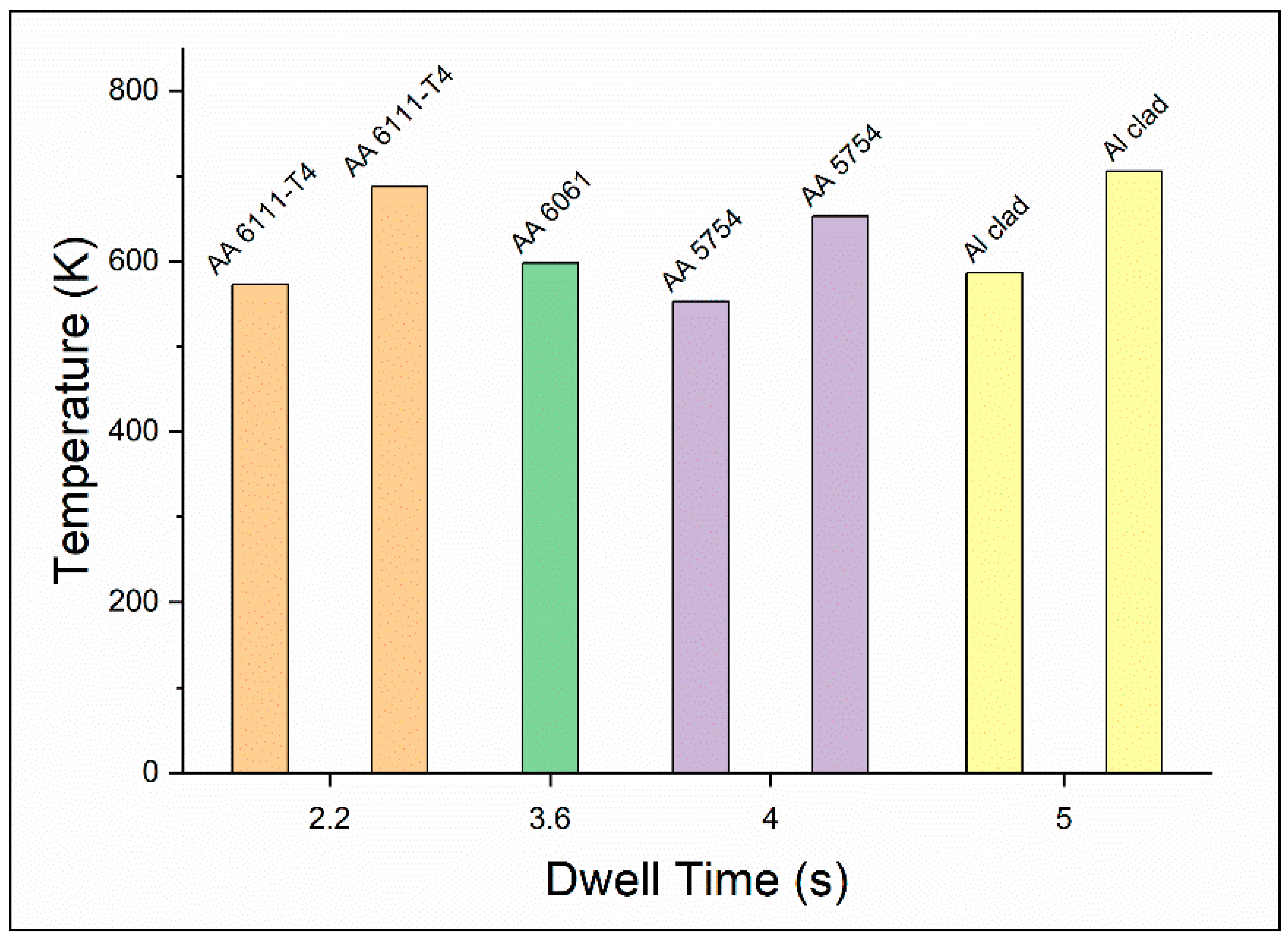
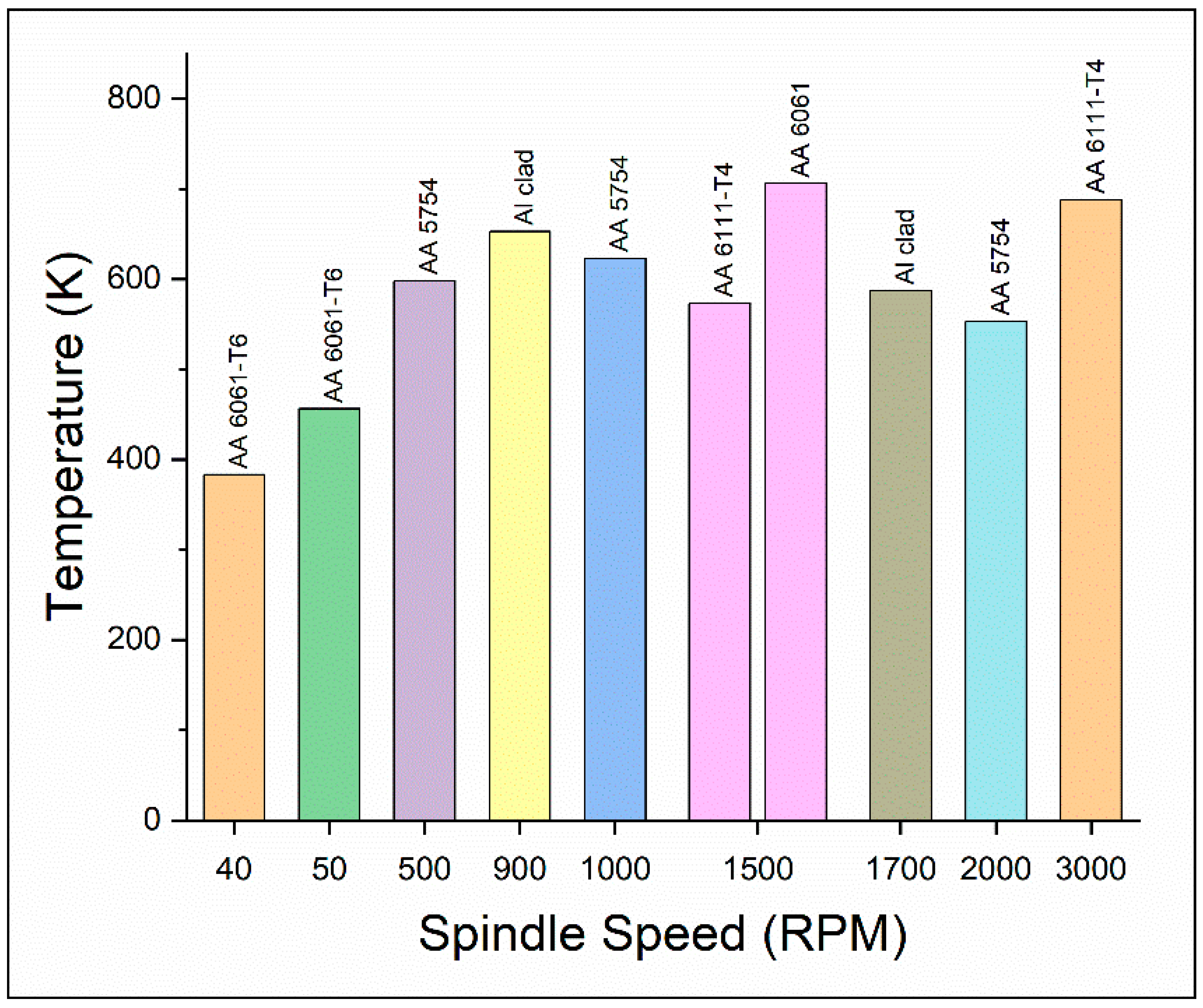
The temperature profile of friction stir spot welding of aluminum alloys is shown in Figure 6 and Figure 7, where the maximum temperature generated during the FSSW of different aluminum alloys at different parameters is revealed. The peak temperature values at different dwell times are shown along the ordinate and dwell time along the abscissa where the type of metal was indicated at the top of the bar.
Figure 6 shows the compiled data of maximum temperature generated at different dwell times, whereas Figure 7 shows the variation of temperature at different speeds. Arul et al. [107] have used Al 6111-T4 sheets with a thickness of 1.3 mm and 1.7 mm as a welding sample and welded by using an H13 tool steel of 10 mm tool diameter. It can be observed that at a dwell time of 2.2 s, the maximum temperature rise was about 573 K at 1500 RPM, and at the same dwell time, at 3000 RPM, the temperature reached up to 688 K. The welding was performed in the Kawasaki SFW system, and the temperature was recorded by using a thermocouple, which was 2 mm away from the shoulder of the tool [107].
Pandey et al. [109] achieved the highest temperature of 598 K at a dwell time of 3.6 s. Aluminum 6061 series of 1 mm thickness was welded with an H-13 tool. The pin length of the tool was 1.4 mm with a diameter of 4 mm at 1500 RPM. A FE or finite element model was developed to compare the experimental data with the predicted data.
Aluminum-5754 sheets of 1.6 mm thickness were welded with a circular pin tool with a diameter of 5 mm by Pathak et al. [71]. The lowest peak temperature recorded at 4 s was 280 °C with an RPM of 500, and the temperature recorded at the same dwell time but at 2000 RPM was 553 K. The study also notes that, if the tool was replaced with a taped pin tool, the peak temperature increases. The circular pin happened to produce more heat than the tapered one, in the specimen, and near the sheet–tool interface, an asymmetrical temperature profile has been observed with both circular and tapered pins. Moreover, with the increase in rotational speed and dwell time, the peak temperature has also been observed to be increasing. The maximum and minimum temperature recorded for a 5 s dwell time was 706 K and 587 K at 1700 RPM and 900 RPM, respectively. Li et al. [110] used Alclad 2A12-T4 aluminum sheets of 2 mm thickness, and the experiment was conducted by a self-developed RFSSW machine that had a 5.3 mm diameter. By using a K-type thermocouple, the thermal cycles were determined, and the readings were obtained 6 mm away from the weld center. The variation in the highest peak temperature and lowest peak temperature takes place due to the variation in the RPM of the given parameters.
Also in a friction welding process, incipient melting may occur, since the shear strength of the plasticized metals tends to decrease significantly if the temperature reaches the solidus temperature. Thus, no further temperature rise takes place as a drop-in heat efficiency occurs in the process. The maximum temperature generated at different spindle speeds is shown in Figure 7. It was observed that the temperature changes with a change in spindle speed. Then, some fluctuation can also be observed until the temperature reaches its highest and then with the increasing RPM, the value of the temperature becomes more identical. From the plot, it can be concluded that the welding peak temperature remains between 523 K and 723 K. The lowest temperature was achieved at low spindle speed, i.e., 40 RPM and 50 RPM because of the low strain rate of the material.
Along with the works on the Aluminum 5XXX and 6XXX series, authors have contributed significantly in the joining of Al 7XXX series, which is popular for its high strength, toughness, and corrosion resistance and it finds the majority of application in aerospace and transportation applications. Both numerical [111] and experimental works have been reported to investigate the effect of the thermal history on the final joint quality (microstructure and mechanical performance) in Al 7XX series welded through the FSSW refill FSSW process. Fully coupled thermal analysis was performed to predict the thermal history for Al 7075-T6 sheets welded by the refill FSSW process. The results were validated with the experimental thermal profile. The model showed a steep thermal gradient near the Stir Zone.
Gerlich et al. [112] reported peak temperatures reaching 527 °C during a traditional FSSW process at 3000 rpm. These high temperatures facilitated dynamic recrystallization, producing fine-grained equiaxed microstructures in the SZ. However, the study also found that high tool speeds could lead to transient local melting and tool slippage, which compromise weld quality. Shen et al. [113] observed melted films in the SZ with maximum temperatures of approximately 470.9 °C located 2.6 mm from the weld center. These elevated temperatures correlated with increased nugget thickness and lap shear strength, indicating a direct relationship between thermal input and joint integrity. However, excessive heat could degrade surrounding material properties. The thermo-mechanical modeling by Janga et al. [114] validated numerical predictions of temperature cycles using thermocouple measurements. Their DEFORM-3D model accurately captured the thermal history (Figure 8), strain, and material flow, highlighting the localized nature of heat generation and its critical role in defining the size and quality of the SZ.
The temperature profile’s impact on weld microstructure was also shown in the work reported by Kubit et al. [115], where micrographs of refill FSSW welds revealed the higher thermal input refined grain structures, but could also lead to softening in the heat-affected zone (HAZ), impacting fatigue strength. It has been observed that the combination of plunge depth and welding time governs the thermal activity [116]. Proper calibration ensures sufficient temperature to plastically deform the material without exceeding its melting point, maintaining the solid-state nature of the process.
Overall, from these studies, it can be understood that peak temperature during the welding process depends on various factors like tool type, dwell time, spindle speed, and tool geometry. High temperatures are essential for the softening of the base material, and on the other hard excessive temperature can cause local melting and generation of residual stresses. Therefore, controlling temperature distribution is very much essential in the FSSW process. Both experimental and numerical analyses emphasize the need for precise process parameter optimization to ensure high-quality joints with favorable mechanical and metallurgical properties.

3. Mechanical Behavior

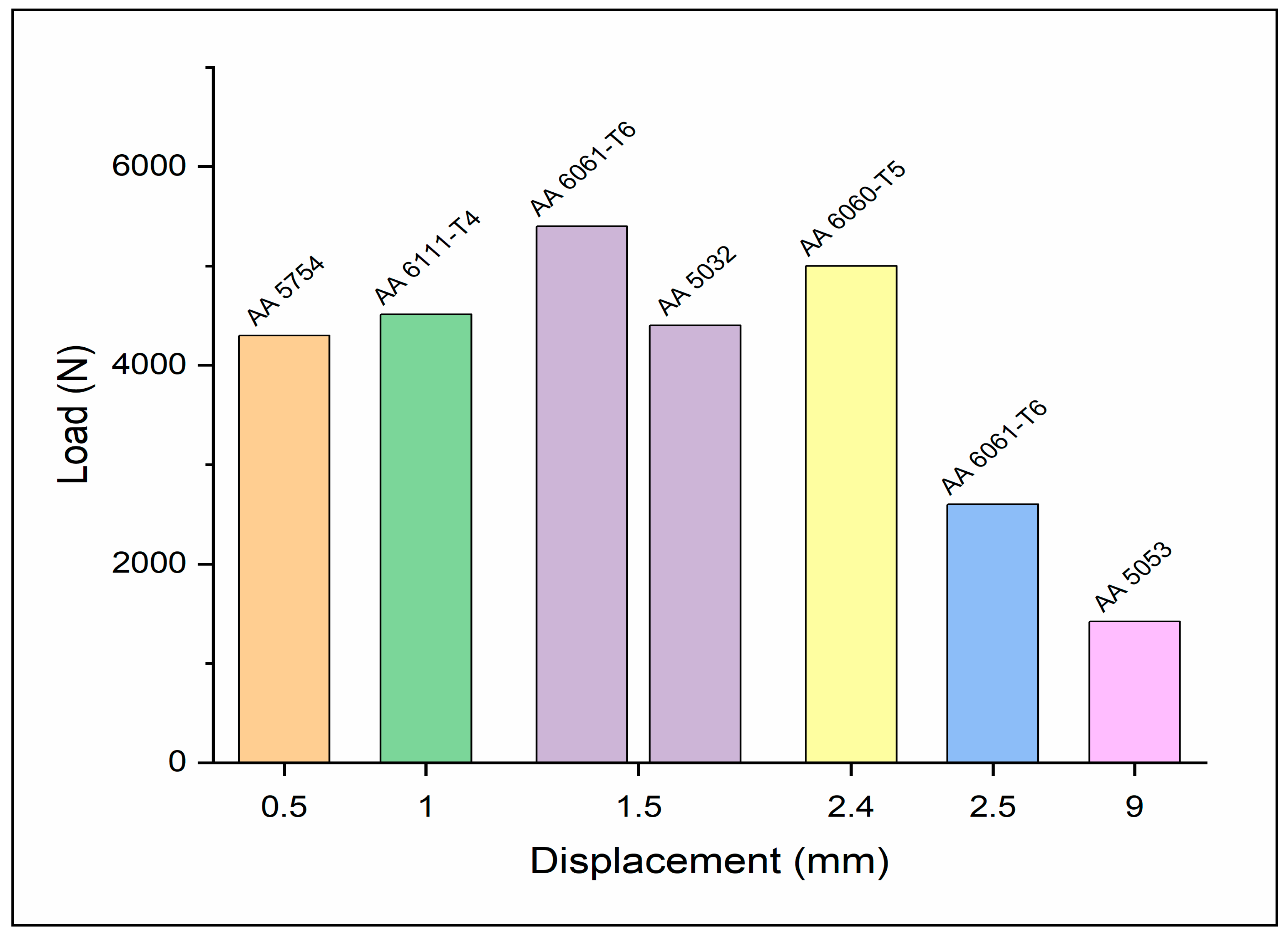
The highest load-bearing capacity at different parametric combinations is shown in Figure 9. The highest load-bearing capacity was achieved by Sun et al. [117] for a probe-less tool. The maximum load-bearing capacity recorded by the FSSW joint of commercial 6061-T6 series of aluminum alloy plate of 1 mm thickness was recorded at 5400 N with a displacement of 1.5 mm.
Pathak et al. [71] analyzed the lap shear load of FSSW on Aluminum-5754 sheets of 1.6 mm thickness on different dwell times, tool plunge depth, and rotational speeds. The parameters used in that experiment are a plunge depth of 2.4 mm, a dwell time of 4 s constant, and a rotational speed of 2000 RPM with a circular pin that has a diameter of 5 mm. The highest load-bearing capacity or the peak load was obtained as 4.3 KN which creates a displacement of 0.5 mm in the specimen [71].
Farmanbar et al. [118] carried out an experiment on AA5052 al sheets of 1 mm thickness, and the type of welding performed was protrusion friction stir spot welding. The protrusion had a diameter of 11 mm and a height of 0.4 mm above the desk. The tool used for this welding was the H13 steel tool which was a pinless cylindrical tool with a 14 mm diameter. Welding was performed with a rotational speed of 800 RPM and with various dwelling times. It was observed that the highest tensile shear load obtained was 4400 N with a displacement of 1.5 mm [118].
The lowest tensile shear load of 1420 N with a displacement of around 9 mm was recorded by Badarinarayan et al. [119] at an RPM of 1500 with a plunge speed of 20 mm/min, dwell time of 2 s, and a plunge depth of 0.2 mm. For the study, annealed 5083AA sheets with two different thicknesses of 1.64 and 1.24 mm were used. A cylindrical pin was used to weld with a shoulder diameter of 12 mm, and a pin length of 1.6 mm. For AA6060-T5 alloys, the tensile shear load was 5000 N with a displacement of 2.4 mm before the rapture. The welding tool used was X210CR 12 with shoulder and a pin diameter of 14 mm and 5 mm, respectively. The tool also had a length of about 3.95 mm. The average failure load or load-bearing capacity was found to be 5 KN with a feed rate of 16 mm/min, along with a rotational speed of 1000 RPM [120]. FSSW of 6061-T6 al alloy of 2 mm thickness extends up to 2.5 mm at a load of 2600 N [32]. The H13 pinless tool was used for welding with a plunge depth of 1.1 mm, 1400 RPM, 6 s dwell time, and 18.6 mm/min feed rate. The study also shows that the weld samples which were made with the same welding parameters but using a tool with the probe have lesser yielded strength [32]. And the rest of the two values are 4512 with a displacement of 1.0 mm.
Residual stress [25,121] is always a matter of concern for any welding process. For the FSSW process, the thermal gradient and the mixing parameters influence the residual stress behavior. The research conducted by Sarfaraz et al. [116] and Boucherit et al. [122] shows the residual stress distribution in the weld center and around (Figure 10) for Al-Cu dissimilar FSSW joints. The highest amount of residual stress (RS) can be seen around the HAZ. The maximum value of RS was around 60 MPa. The longitudinal RS was reduced near the spot weld center. The SZ also noticed a decreased value of the RS, which may be due to the finer grains in this region. Though very less efforts have been found in the investigation of the residual stresses in the FSSW process, the presence of the residual stresses in the FSSW joint is much less compared to the fusion welding process [123]. The estimation of the RS could be an area for understanding the FSSP process in a better way.
Recent advancements in the application of FSSW have extended beyond sheet joining and are now being explored for structural aluminum members such as beams, columns, and stiffened panels [124]. These developments are particularly significant in automotive and rail car body frames, where lightweight [121] and high-load-bearing components are essential. For example, FSSW has been applied to the fabrication of aluminum hollow extrusions and stiffeners used in crash-relevant substructures, enabling enhanced joint fatigue performance and crash energy absorption compared to traditional joining methods [125]. Aerospace-grade aluminum alloys (e.g., 7075) are being considered for structural ribs and bulkhead components using FSSW due to the lower residual stresses and improved dimensional stability offered by the process [124]. These applications demonstrate FSSW’s scalability and reinforce the need to evaluate its design feasibility and mechanical reliability under large-scale loading scenarios [124,125,126].

4. Microhardness

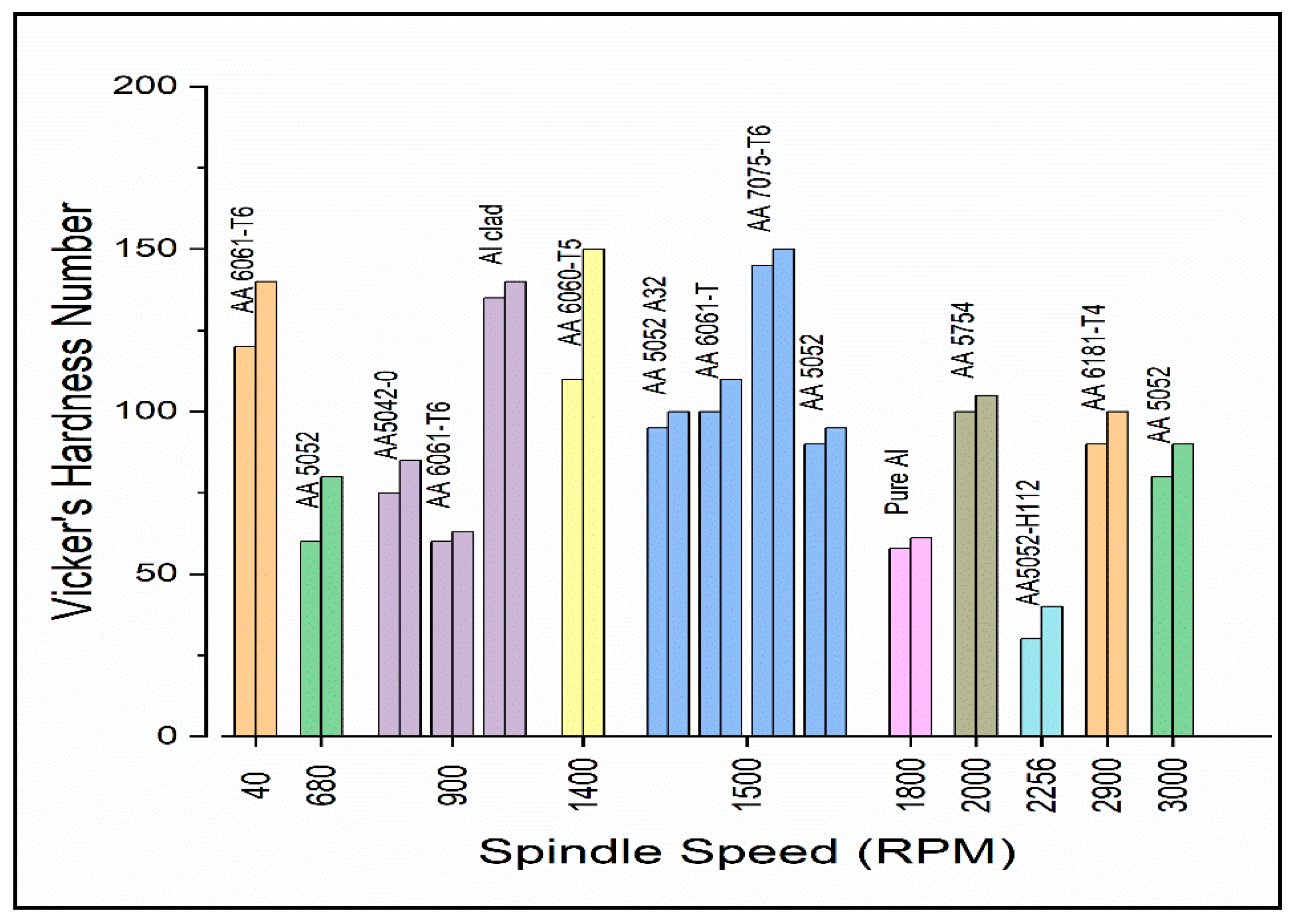
The graph provided below represents the hardness profile of different aluminum alloys at different process parameters by various authors. Figure 11 shows the range of microhardness values at different spindle speeds ranging from 40 RPM to 3000 RPM, which gives a brief idea of the range of hardness values of friction stir spot welded joints of Al alloy. The compilation of highest and lowest hardness numbers by various authors was plotted for different spindle speeds and the type of the welded material was mentioned along with the bar in the graph.
It can be observed from Figure 11 that the value of microhardness of FSSW of aluminum alloy ranges between 55 HV to 160 HV depending on the input parameters. The highest microhardness in an aluminum series of 6060-T5 was achieved by Mohamed et al. [120] with a 14 mm shoulder diameter, 5 mm pin diameter, and 3.95 mm length at rotational speed from 1000 to 2000 RPM. The hardness value of the Stir Zone (SZ) and thermo-mechanical-affected zone (TMAZ) was higher than the base material and the HV in the SZ showed a peak value in the range of 110–150 with a rotational speed of 1400 RPM. The highest hardness value of 150 HV was recorded in the welding joint welded at a rotational speed of 1400 RPM. Sun et al. [117] used commercial 6061-T6 Al alloy plates with a thickness of 1 mm for that experimental process. Two types of tools were used for the analysis; one of the rotating tools had a diameter of 12 mm along with a probe diameter of 4 mm, and the length was 1 mm. The other rotating tool was flat-shouldered, i.e., probe less tool with a diameter of 12 mm. The hardness value noted in the range of 120–140 HV was achieved in the joints welded at a spindle speed of 40 RPM and welding time of 30 s. The hardness values changed slightly if probe-less tools were used for welding
Another experiment was carried out on AA5042-O al with 1.5 mm thickness by Tiera [127]. The welding was carried out by using the FSSW-Refill prototype machine which had an 18 mm diameter clamping ring, a 9 mm diameter threaded sleeve, and a 5.2 mm diameter grooved pin. At a tool speed of 900 RPM and 6.07 KN applied load, the hardness value was found to be 75–85 HV. Aluminum 6061-T6 rolled sheets of 2 mm thickness were chosen by Venukumar et al. [128] to analyze the welding properties. The tool which was used for the experiment had a shoulder diameter of 18 mm and a pin diameter of 5 mm. It was observed that the hardness was in the range of 60–63 HV with a rotational speed of 900 RPM. The hardness value of alclad 2A12-T4 aluminum alloy had a thickness of 2 mm and range of 135–140 with a rotational speed of 900 RPM in the SZ [110]. This alloy also showcases a hardness profile of W-shaped. The HV value was at its lowest (116 HV) near the edges of the Stir Zone. But then again, the hardness value increases in the SZ.
From the graph, it can be observed that four values of hardness were discussed for different Al alloys at 1500 RPM. These values are a compilation of experiments carried out by different authors, which are being discussed. Freeney et al. [129] carried an experiment with a 5052 H32 Al alloy of 1 mm and 1.6 mm thickness. The tool with a shoulder diameter of 12 mm, and a 1.77 mm long conical pin with a root diameter of 4.5 mm and a tip diameter of 3 mm was used for welding. At a rotational speed of 1500 RPM, the value of the hardness was in the range of 90–95 HV, and the hardness value decreased at a rotational speed of 3000 RPM in the range of 80–90 HV. The authors found that the factor affecting the HV values was dwelling time, but the only changes in the RPM do not make significant differences in HV values. It was also noted that at a speed of 680 RPM, the hardness value ranges between 60 and 80 HV. Aluminum alloy 6061 of 1 mm thickness was used by Pandey et al. [109] to conduct the study and found that the hardness was in the range of 100–110 near the edges of the Stir Zone at a spindle speed of 1500 RPM. The edges of the Stir Zone experience high material flow and due to the compression of more material at those points, the hardness values are usually higher. Another study by Badarinarayan et al. [119] was conducted by using Annealed 5083 Al sheets with two different thicknesses at a spindle speed value of 95–100 HV with an RPM of 1500. This alloy had a higher hardness value in the SZ than the BM and with a distance of around 2 mm from the periphery of the weld keyhole, the HV values were lower and quite stable at the same time. Shen et al. [130] experimented with a 7075-T6 aluminum alloy plate of 2.0 mm thickness. The hardness values of the same experiment range between 145 and 150 in the SZ area at 1500 RPM. The HV distribution was W-shaped and the lowest hardness values were obtained at the boundaries of the HAZ and TMAZ. The factor affecting the HV values was dwelling time, but the only change in spindle speed does not make significant changes in HV values. Freeney et al. [129] selected strained hardened 5052 H32 aluminum alloy to conduct their study. The next bar represents the HV value of the same study which ranges from 90–95 at the boundaries of the SZ, at a spindle speed of 1500 RPM.
The HV value of SZ of commercially pure aluminum was found to be in the range of58–61 HV at a constant speed of 1800 RPM [9]. The HV distribution had a W-shaped appearance and the hardness values were lower in the HAZ. Also, the hardness value was found to be maximum in the SZ due to the formation of the fine grains. Pathak et al. [71] studied Aluminum-5754 sheets with a thickness of 1.6 mm for FSSW and found that the hardness value was in the range of 100–105 HV with a rotational speed of 2000 RPM when a distance of 2 mm from the keyhole was considered. Due to the fine dynamic recrystallization of the grain structure, the hardness values were higher in the nugget zone. Aluminum alloy 5052-H112 sheets of 1 mm thickness were used by Zhang et.al. [131] for analyzing the effect of parameters on the welding properties. The tool with a shoulder diameter, root, and tip of the pin of 10, 4.5, and 3 mm, respectively, was used for FSSW, respectively. The pin was about 1.8 mm in length and the concave face of the shoulder was angled at 4°. With a spindle speed of 2256 RPM and a dwell time of 5 s, the highest hardness value ranges between 30 and 40 HV in the SZ. The HV values had a W-shaped appearance and the hardness was found to be lowest in the HAZ and lower in the BM. One of the highest HV values (30–40) only near SZ was achieved at 2256 RPM; the spindle speed and dwell time influenced hardness values.
At an RPM of 2900, the hardness value was in the range of 80–100 HV. The experimental work was carried out by Rosendo et al. [132] using 1.7 mm thick sheets of AA6181-T4 aluminum alloy. The base metal has an average hardness value of 80 HV but it decreases in the HAZ. The SZ goes through dynamic recrystallization which leads to solubilization of the precipitates. Hence, this process was considered one of the main reasons behind the higher value of hardness in the SZ.

5. Microstructure

The weld zone in FSSW is composed of several regions, each exhibiting distinct microstructural characteristics. The Stir Zone (SZ), also known as the nugget zone, undergoes significant plastic deformation and dynamic recrystallization, resulting in a fine and equiaxed grain structure due to the intense stirring action of the tool. Adjacent to the SZ is the Thermo-Mechanically Affected Zone (TMAZ), which experiences both thermal and mechanical effects. However, the degree of plastic deformation here is less intense compared to the SZ, leading to elongated and deformed grains from the combined effects of heat and mechanical stirring. The Heat-Affected Zone (HAZ) is subjected to thermal cycles without undergoing plastic deformation. Its grain structure remains similar to the base material but may show signs of thermal exposure, such as grain growth or phase changes. Lastly, the Base Material (BM) represents the unaffected parent material, retaining its original microstructure. Figure 12A shows the microstructure of the Stir Zone (Stir Nugget), TMAZ, and HAZ [133].
The Stir Zone (SZ) typically features fine and equiaxed grains resulting from dynamic recrystallization. In contrast, the Thermo-Mechanically Affected Zone (TMAZ) exhibits elongated grains aligned with the material flow direction. The Heat-Affected Zone (HAZ) shows minimal changes in grain structure compared to the Base Material (BM). In precipitation-hardened aluminum alloys, thermal cycles can alter the distribution and morphology of precipitates. The SZ often displays a more uniform distribution of fine precipitates due to recrystallization and subsequent re-precipitation. Second-phase particles, such as intermetallic compounds, can be broken up and redistributed within the SZ. The SZ may also develop a unique crystallographic texture due to severe plastic deformation. The TMAZ and HAZ retain some of the original texture of the BM, though modified by thermal and mechanical effects. Intense plastic deformation and dynamic recrystallization in the Stir Zone (SZ) result in significant grain refinement. The stirring action also helps homogenize the distribution of alloying elements and second-phase particles. Additionally, thermal cycles and plastic deformation can introduce residual stresses, potentially affecting the mechanical properties of the weld. Understanding the microstructural evolution during FSSW of aluminum alloys is essential for optimizing welding parameters and enhancing the performance of the welded joints.
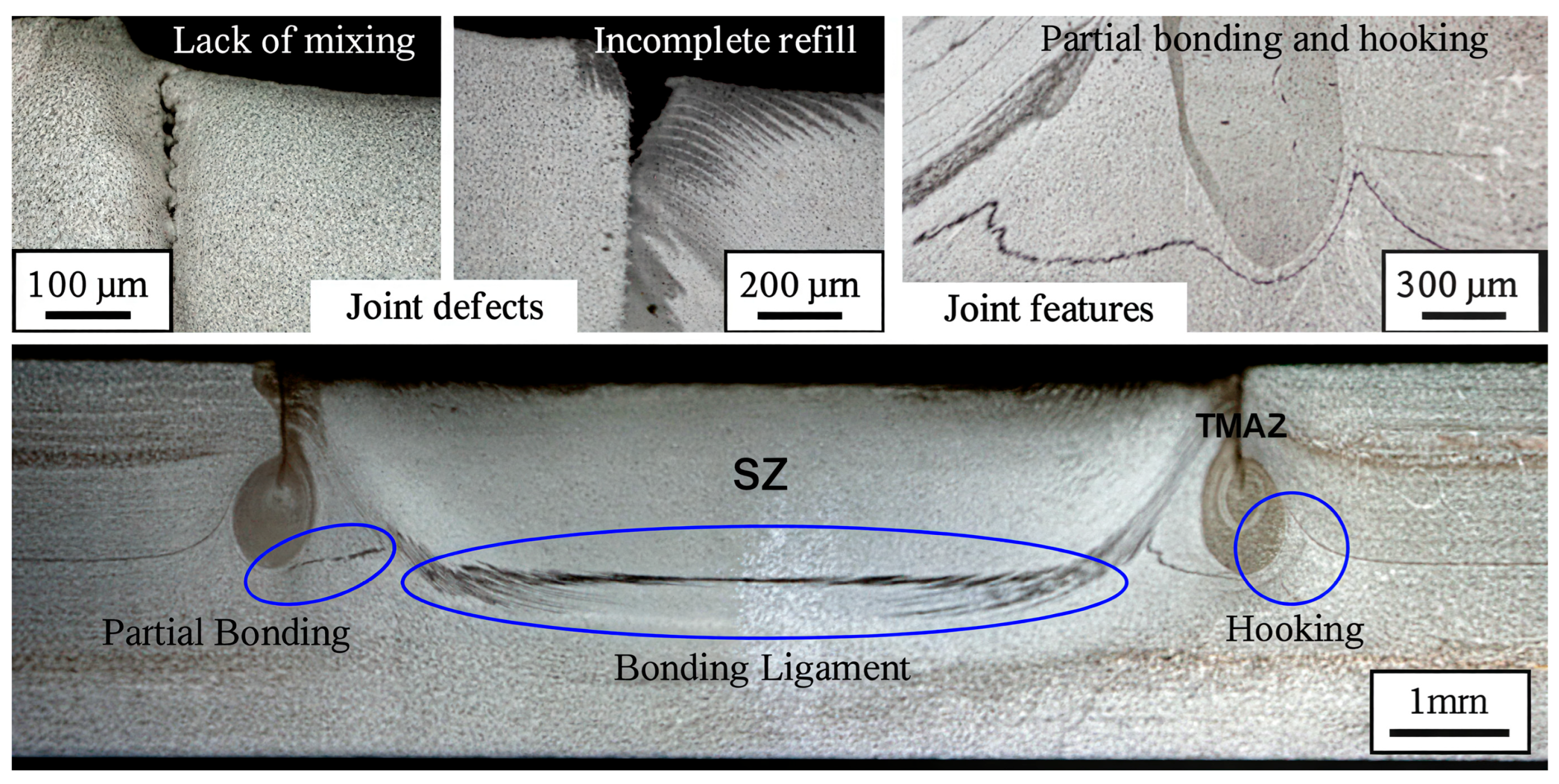
The microstructure of the parent material in the FSW process remains relatively unchanged in the Heat-Affected Zone (HAZ) with minimal effect on grain structure. Dynamic recrystallization occurs in the DXZ with subgrain growth absorbing dislocations into boundaries. Precipitates in the base alloy coarsen and increase in the HAZ after FSW. Al3Zr dispersoids remain unchanged in HAZ and TMAZ regions but act as nucleation sites in the DXZ where as Al7Cu2Fe phase changes shape in the DXZ due to FSW tool stirring [1]. A macrostructural investigation revealed two distinct FSpW weld regions: the Stir Zone (SZ) and the Thermo-Mechanically Affected Zone (TMAZ), as shown in Figure 13. Analysis of the cross sections found consistent geometric and metallurgical patterns in all connections investigated, including hooking, partial bonding, and bonding ligament. The hook is created by the upward bending of the sheet due to tool penetration, forming an upside-down V shape controlled by energy input. Partial bonding is a weaker transition area between sheets, while the bonding ligament represents strong adhesion resistant to separation [132].
The RFSSW process produces a more homogeneous and refined microstructure in the Stir Zone (SZ), leading to different hardness values along the welded joint. The SZ also exhibits higher localized corrosion resistance and thicker passive film compared to the Base Material (BM) and Heat-Affected Zone (HAZ), making RFSSW a promising option for welding dissimilar joints [34]. Figure 14 shows the difference of grain size in the Stir Zone (SZ) and Thermo-Mechanically Affected Zone (TMAZ) at various tool rotational speeds. As the tool rotational speed increases from 900 to 1700 RPM, the change in average grain sizes occurs in the SZ. The elevated temperature provides more energy for grain growth, leading to grain coarsening in the recrystallized grains in the SZ. Similarly, in the TMAZ, grains also become coarser at higher rotational speeds for the same reason [110].
Authors have tried to analyze micro fracture surfaces of tensile-tested specimens using SEM to understand failure patterns. Figure 15 shows two micro graphs of welded samples with and without heat treatment. Fractured surfaces showed dimples of various sizes and shapes, indicating ductile fracture. Voids typically form before necking in ductile materials, but early necking can lead to more prominent void formation. Heat-treated specimens showed shallow and small dimples, while welded joints had deep and elongated dimples. A larger population of fine dimples indicated a more ductile behavior before failure. Similar findings were reported for fatigue-tested FSW joints [49].
The formation of intermetallics is a matter of concern in most of the friction stir processes as the intermetallic compounds are generally brittle in nature, hence weakening the joint and it can produce further fracture to the joint [134]. Intermetallics can be formed more in the liquid–solid interface than the solid–solid interface [135].
Friction stir welding can be beneficial in some cases where it can limit the formation of the intermetallics. Authors have reported that dissimilar Al-Mg joints formed by fusion welds have more tendency to form the intermetallics than the FSW joints. Various types of IMCs can be observed for the dissimilar Al-Mg: β-Al3Mg2 and γ-Al12Mg17, etc. There is definite effect of the process parameters on the formation of the IMCs. Lv et al. [135] reported that tool offset can influence the overall thickness of the IMC layer. The utilization of the ultrasonic energy disjointed the IMCs and in turn enhanced the strength. With higher ultrasonic energy the complete removal of the IMCs is also possible. Baghdadi et al. [136] reported that the mechanical property is mainly affected by the IMCs which can be controlled by controlling the process parameters.
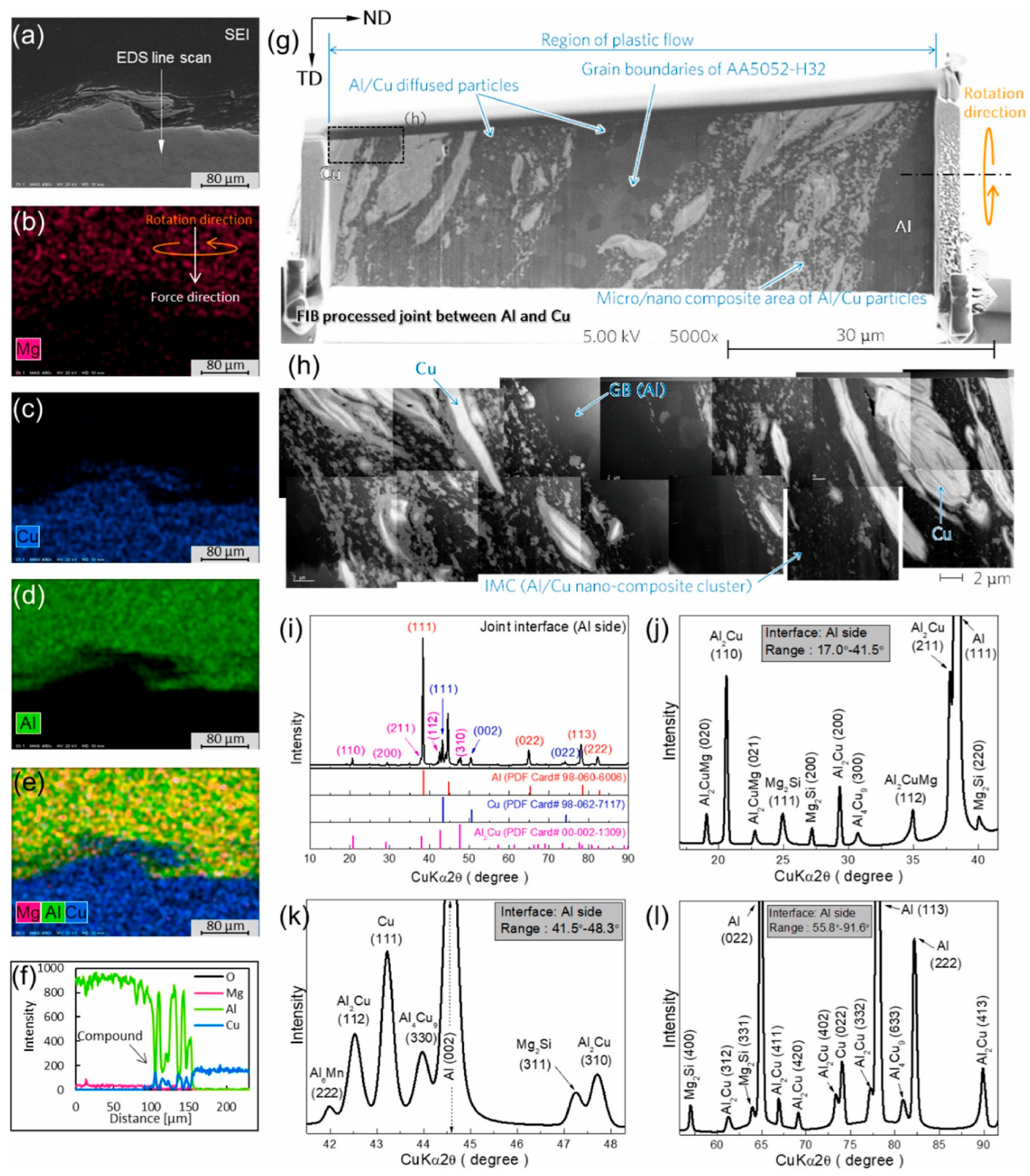
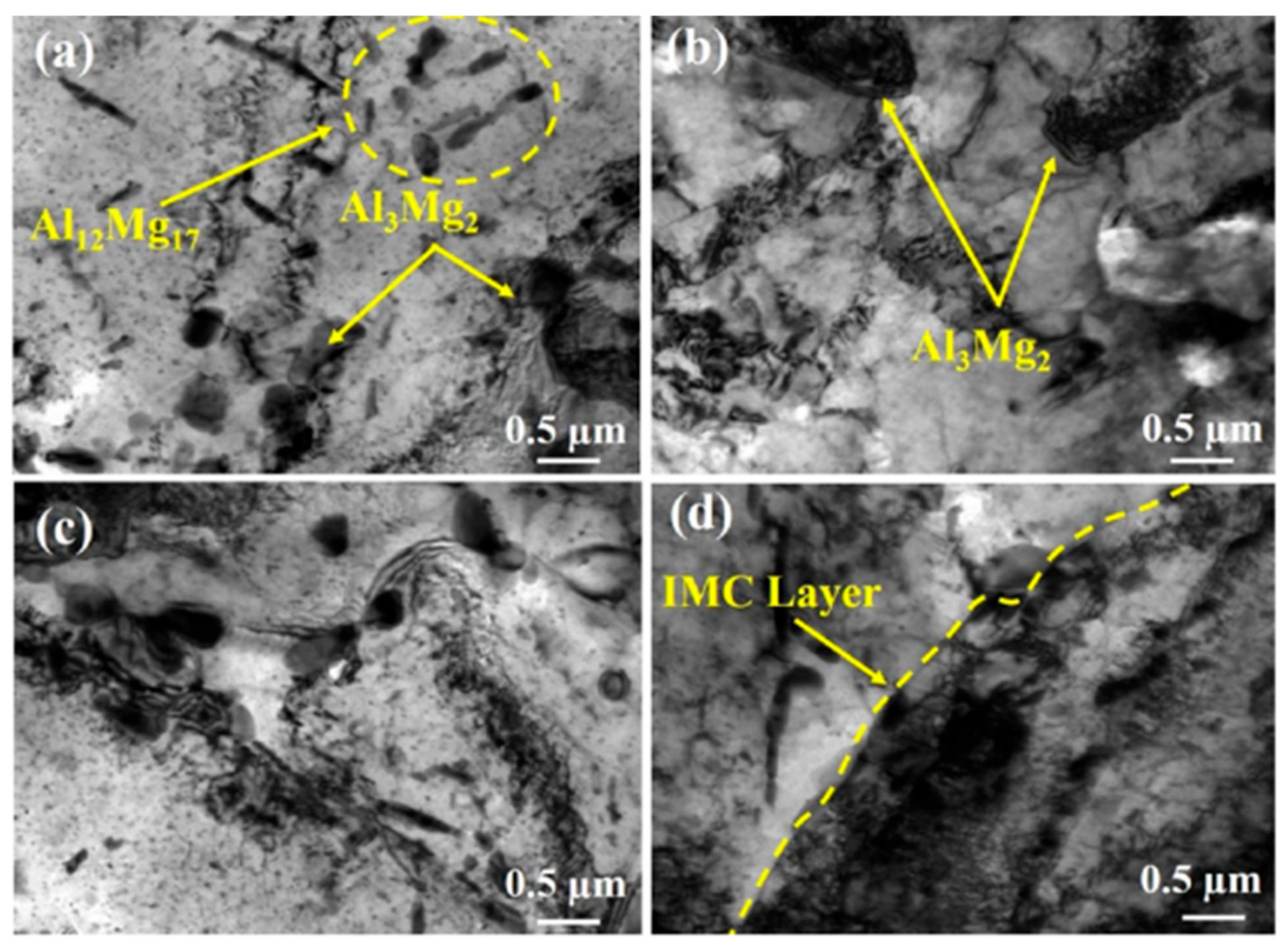
Among the popular methods, energy dispersive spectroscopy, X-Ray diffraction (Figure 16), etc., can be used to investigate the presence of the IMCs. As reported by Medhi at al. [25], the inter-diffusion performance of Al and Mg was responsible for the formation the IMCs (Al12Mg17 and Al3Mg2). TEM images as shown in Figure 17 also confirm the presence of the IMC in the Stir Zone at various tool rotational speeds. The investigation by Kim et al. [137] shows an in-depth analysis of the Al-Cu joint welded by the refill FSSP. It was reported that definite inter-metallic formation was found during the FSSW process (Figure 16). Intermetallic lumps composed of a variety of the inter-metallic compounds of the aluminum, viz., Al4Cu9, Al2Cu, Al6Mn, and Al2CuMg was observed at various locations at the joint interface.
The intermetallic formation plays a very significant role for deciding the final mechanical behavior of the joint. As the joint strength of the friction stir spot welding process depends on both the mechanical locking due to mixing and the partial change in the microstructure, the inter-metallic formation can significantly influence the joint strength and fatigue behavior. Therefore, the process parameters should be controlled precisely to decide the final microstructural behavior of the weld joint for a sound joint, otherwise it may lead to premature failure of the joint.

6. Design Rules and Code Comparisons for FSSW of Aluminum Alloys

Although friction stir spot welding (FSSW) is widely researched, its inclusion in formal design codes is still in a developmental stage. However, some progress has been made in incorporating spot welding practices, including those applicable to aluminum alloys, in various regional standards such as the Eurocode 9 [138], American Welding Society (AWS) D17.3/D17.3M [139], AS/NZS 1665 [140], CSA S157 [141] and AISC Manual [142]. The Table 3 below provides a comparative summary of these standards with respect to aluminum spot welding, particularly highlighting provisions relevant to FSSW or translatable from resistance spot welding (RSW).
Currently, most design codes do not directly incorporate provisions for FSSW of aluminum alloys. Instead, design engineers and researchers often rely on RSW design principles as a baseline, adjusted for the improved mechanical behavior and reliability of FSSW joints [121,143,144]. AWS D17.3 [139] is the only available design which talks about friction welding techniques, making it the most relevant framework currently available, especially for aerospace applications.
The lack of harmonized and FSSW-specific design equations presents a major limitation, particularly when adopting FSSW in load-bearing or fatigue-sensitive structures. Variability in experimental data, differences in alloy behavior, and tool configuration challenges complicate the development of universal equations. To bridge this gap, future efforts should aim to establish standardized design protocols for FSSW based on comprehensive experimental validation, fatigue life assessment, and numerical simulation [136]. These could then feed into code revisions or the creation of dedicated FSSW appendices within existing welding standards.

7. Summary

In the past few years, rampant growth has been maintained for the investigation of FSSW for aluminum alloys. A huge number of promising results have been obtained which include the wide application of FSSW for various industries. This is why the FSSW process plays an important role to reduce pollutant emissions, and moreover, this process requires less temperature than the melting point. Moreover, this method is also used for the overlap joining of aluminum alloys which are not weldable by traditional techniques. Though due to limited scope, this study could not cover a few of the areas like the modeling and simulation works and microstructural study of the FSSW joints, but rather a multifold analysis of the recent studies on FSSW has been performed. To maximize the application of FSSW with minimum defects, various experiments were carried out by worldwide researchers, which concludes the following points:
  • It can be seen that a wide range of tool materials are being used; H13 is the most widely used, other popular ones are HSS, C40, CBN, etc.
  • From the study, it can be concluded that the peak welding temperatures vary from 280 °C to 450 °C and there is an increase in temperature with an increase in RPM; however, it depends upon the aluminum grade.
  • Most of the researchers have performed the Vicker’s hardness study for all the similar Al FSSW welding ranges of 50–160 HV, where HV at the Stir Zone of the upper plate has the highest hardness value.
  • For achieving the highest load-bearing capacity, the dwell time should be kept minimum and the load-bearing capacity can be slightly improved using a pinless tool.
  • Numerous researchers have conducted tensile testing of the FSSW joints, Al 6XXX series seems to show the maximum load-bearing capacity.
  • From the studies, it is evident that the thermal history has a critical influence on the final mechanical behavior.
  • Studies have been conducted to analyze the design standards, and it was found that currently there is no defined standard for the FSSW process, at present only AWS has a specific standard for the friction stir welding.

8. Future Directions

The current review has highlighted several critical aspects and recent developments in friction stir spot welding (FSSW) of aluminum alloys, particularly emphasizing tool design, temperature control, mechanical behavior, microstructural evolution, and process outcomes. While FSSW has shown clear advantages over conventional welding techniques, several research gaps and opportunities for advancement remain.
One of the key findings of this review is the pivotal role of tool geometry and material in controlling heat generation and material flow. Future research should focus on the design and optimization of non-traditional tool geometries, including multi-featured and adaptive tools, to enhance weld quality and reduce cycle time. Additionally, while tool steels and PCBN tools have been extensively studied, the development of cost-effective, high-durability alternatives, especially for dissimilar or high-strength aluminum alloys, remains underexplored.
A scope can be the comparative study with the other variants of the spot welding processes (RSW, LFW, or hybrid processes) with the merits and demerits of the solid-state process. There is a need for real-time process monitoring and closed-loop control systems to ensure repeatability and consistency. Advanced sensing techniques (e.g., thermography, acoustic emission, and force feedback) coupled with AI-based predictive models could enable adaptive process control tailored to material and joint conditions.
Residual stress evolution and its interaction with microstructure, particularly in multi-pass or hybrid processes, require deeper investigation through coupled thermo-mechanical simulations validated by experimental methods such as neutron diffraction and digital image correlation. Furthermore, long-term performance studies, including fatigue, corrosion resistance, and fracture behavior under service-like conditions, are essential to validate FSSW joints for critical applications in aerospace and automotive structures.
Standardization of design rules specific to FSSW by reviewing and harmonizing provisions across Eurocodes, AWS, and AS/NZS standards is crucial for broader structural implementation. Comparative analysis and experimental validation of design equations can provide a foundation for code development and improve industry acceptance.
In a nutshell, the future of FSSW research lies in a multidisciplinary approach, integrating materials science, mechanical engineering, process modeling, and machine learning. The insights from this review provide a roadmap for developing a more robust, intelligent, and industrially scalable FSSW process for aluminum alloys.

Author Contributions

Conceptualization, B.H. and B.L.; methodology, M.J.B., K.S., B.H., A.K.M. and H.J.; validation, A.K.M., B.L. and H.J.; formal analysis, Y.N., A.K.M. and H.J.; investigation, K.S.; resources, K.S.; data curation, M.J.B. and A.K.M.; writing—original draft preparation, M.J.B., Y.N., B.H., A.K.M., B.L. and H.J.; writing—review and editing, Y.N., B.H., A.K.M. and H.J.; visualization, Y.N., B.H., A.K.M., B.L. and H.J.; supervision, A.K.M.; project administration, B.H. and A.K.M.; funding acquisition, B.H. and B.L. All authors have read and agreed to the published version of the manuscript.

Funding

This work was supported and funded by the Deanship of Scientific Research at Imam Mohammad Ibn Saud Islamic University (IMSIU) (grant number IMSIU-DDRSP2502).

Data Availability Statement

No new data were created or analyzed in this study. Data sharing is not applicable to this article.

Acknowledgments

The authors are thankful to the National Institute of Technical Teachers’ Training & Research (NITTTR), Kolkata for continuous support.

Conflicts of Interest

The authors declare that they have no conflicts of interest.

References

  1. Su, J.Q.; Nelson, T.W.; Mishra, R.; Mahoney, M. Microstructural investigation of friction stir welded 7050-T651 aluminium. Acta Mater. 2003, 51, 713–729. [Google Scholar] [CrossRef]
  2. Mubiayi, M.P.; Akinlabi, E.T.; Makhatha, M.E. Current state of friction stir spot welding between aluminium and copper. Mater. Today Proc. 2018, 5, 18633–18640. [Google Scholar] [CrossRef]
  3. Çam, G.; Mistikoglu, S. Recent developments in friction stir welding of al-Alloys. J. Mater. Eng. Perform. 2014, 23, 1936–1953. [Google Scholar] [CrossRef]
  4. Lin, Y.C.; Liu, J.J.; Chen, J.N. Material flow tracking for various tool geometries during the friction stir spot welding process. J. Mater. Eng. Perform. 2013, 22, 3674–3683. [Google Scholar] [CrossRef]
  5. Shen, Z.; Ding, Y.; Gerlich, A.P. Advances in friction stir spot welding. Crit. Rev. Solid State Mater. Sci. 2019, 45, 457–534. [Google Scholar] [CrossRef]
  6. Hsu, T.I.; Wu, L.T.; Tsai, M.H. Resistance and friction stir spot welding of dual-phase (DP 780)—A comparative study. Int. J. Adv. Manuf. Technol. 2018, 97, 2293–2299. [Google Scholar] [CrossRef]
  7. Yang, X.W.; Fu, T.; Li, W.Y. Friction stir spot welding: A review on joint macro- and microstructure, property, and process modelling. Adv. Mater. Sci. Eng. 2014, 2014, 697170. [Google Scholar] [CrossRef]
  8. Andalib, H.; Farahani, M.; Enami, M. Study on the new friction stir spot weld joint reinforcement technique on 5754 aluminum alloy. Proc. Inst. Mech. Eng. Part C J. Mech. Eng. Sci 2018, 232, 2976–2986. [Google Scholar] [CrossRef]
  9. Venukumar, S.; Muthukumaran, S.; Swaroop, Y. Microstructure and mechanical properties of refilled friction stir spot welding of commercial pure aluminium. Mater. Sci. Forum 2013, 765, 776–780. [Google Scholar] [CrossRef]
  10. Ahmed, M.M.Z.; EI-Sayed Seleman, M.M.; Fydrych, D.; Çam, G. Friction Stir Welding of Aluminum in the Aerospace Industry: The Current Progress and State-of-the-Art Review. Materials 2023, 16, 2971. [Google Scholar] [CrossRef]
  11. Sengupta, K.; Chowdhury, I.; Banerjee, A.; Mondal, A.K.; Bose, D. Analysis of suitability of WC tool for joining Inconel 601 alloy by electric assisted friction stir welding. Mater. Today Proc. 2022, 60, 2093–2098. [Google Scholar] [CrossRef]
  12. Sengupta, K.; Mondal, A.K.; Bose, D.; Chowdhury, I. Experimental Investigation on Metallurgical Properties on Effect of Dual Hybridization by Ultrasonic and Electric Energy in Friction Stir Welding for Joining Inconel 625 to Stainless Steel 304. Trans. Indian Inst. Met. 2024, 77, 941–953. [Google Scholar] [CrossRef]
  13. Chowdhury, I.D.; Sengupta, K.; Singh, D.K.; Maji, K.K.; Roy, S.; Ghosal, S.; Mondal, A.K. Investigation of mechanical properties of dissimilar joint of 6063 aluminium and C26000 copper alloy by friction stir welding. Mater. Today Proc. 2021, 44, 4039–4047. [Google Scholar] [CrossRef]
  14. Sengupta, K.; Singh, D.K.; Mondal, A.K.; Bose, D.; Patra, D.; Dhar, A. Characterization of tool wear in similar and dissimilar joints of MS and SS using EAFSW. Mater. Today Proc. 2021, 44, 3967–3975. [Google Scholar] [CrossRef]
  15. Shen, Z.; Ding, Y.; Guo, W.; Hou, W.; Liu, X.; Chen, H.; Liu, F.; Li, W.; Gerlich, A. Refill Friction Stir Spot Welding Al Alloy to Copper via Pure Metallurgical Joining Mechanism. Chin. J. Mech. Eng. 2021, 34, 75. [Google Scholar] [CrossRef]
  16. Myśliwiec, P.; Kubit, A.; Szawara, P. Optimization of 2024-T3 Aluminum Alloy Friction Stir Welding Using Random Forest, XGBoost, and MLP Machine Learning Techniques. Materials 2024, 17, 1452. [Google Scholar] [CrossRef]
  17. Mehdi, H.; Singh, J.; Mouria, P.K.; Mishra, S.; Prakash, C. Effect of Tool Pin Profile on Mechanical and Metallurgical Properties of the Friction Stir Welded Joint of AA6061 and AZ91D. J. Mater. Eng. Perform. 2025, 34, 7976–7990. [Google Scholar] [CrossRef]
  18. Mehdi, H.; Singh, B.; Salah, A.N.; Dubey, M.K.; Mishra, S.; Kumar, S. Effect of PWHT on metallurgical and mechanical characterization of dissimilar welded joint of P91 and P92 steels. J. Adhes. Sci. Technol. 2024, 38, 1395–1412. [Google Scholar] [CrossRef]
  19. Reyaz, M.S.B.; Sinha, A.N.; Mehdi, H.; Murtaza, Q. Effect of Pulsed TIG Welding Parameters on the Microstructural Evolution and Mechanical Properties of Dissimilar AA6061-T6 and AA7075-T6 Weldments. Arab. J. Sci. Eng. 2024, 49, 10891–10911. [Google Scholar] [CrossRef]
  20. Kumar, J.; Kumar, G.; Mehdi, H.; Kumar, M. Optimization of FSW parameters on mechanical properties of different aluminum alloys of AA6082 and AA7050 by response surface methodology. Int. J. Interact. Des. Manuf. 2024, 18, 1359–1371. [Google Scholar] [CrossRef]
  21. Mehdi, H.; Batra, L.; Singh, A.P.; Malla, C. Multi-response optimization of FSW process parameters of dissimilar aluminum alloys of AA2014 and AA6061 by response surface methodology (RSM). Int. J. Interact. Des. Manuf. 2024, 18, 1507–1522. [Google Scholar] [CrossRef]
  22. Jain, S.; Mishra, R.S.; Mehdi, H.; Gupta, R.; Dubey, A.K. Optimization of processing variables of friction stir welded dissimilar composite joints of AA6061 and AA7075 using response surface methodology. J. Adhes. Sci. Technol. 2024, 38, 949–968. [Google Scholar] [CrossRef]
  23. Msomi, V.; Mabuwa, S.; Ngonda, T.; Mehdi, H.; Saxena, K.K. Microstructure and mechanical properties of tungsten inert gas welded dissimilar aluminum alloys joint subjected to normal multi-pass friction stir process. Proc. Inst. Mech. Eng. Part E J. Process Mech. Eng. 2023, 235, 2531–2546. [Google Scholar] [CrossRef]
  24. Mehdi, H.; Jain, S.; Salah, A.N.; Singh, A.P.; Chawla, S. Effect of friction stir welding parameters on microstructure and mechanical properties of the dissimilar alloys of AZ91D and AA7075. Proc. Inst. Mech. Eng. Part E J. Process Mech. Eng. 2023, 239. [Google Scholar] [CrossRef]
  25. Mehdi, H.; Jain, S.; Msomi, V.; Mabuwa, S.; Malla, C. Effect of Intermetallic Compounds on Mechanical and Microstructural Properties of Dissimilar Alloys Al-7Si/AZ91D. J. Mater. Eng. Perform. 2023, 33, 4781–4793. [Google Scholar] [CrossRef]
  26. Jain, S.; Mishra, R.S.; Mehdi, H. Influence of SiC Microparticles and Multi-Pass FSW on Weld Quality of the AA6082 and AA5083 Dissimilar Joints. Silicon 2023, 15, 6185–6197. [Google Scholar] [CrossRef]
  27. Boldsaikhan, E.; Fukada, S.; Fujimoto, M.; Kamimuki, K.; Okada, H. Refill friction stir spot welding of surface-treated aerospace aluminum alloys with faying-surface sealant. J. Manuf. Process. 2019, 42, 113–120. [Google Scholar] [CrossRef]
  28. Yuan, W. Friction Stir Spot Welding of Aluminum Alloys. Master’s Thesis, Missouri University of Science and Technology, Rolla, MO, USA, 2008. Available online: https://scholarsmine.mst.edu/masters_theses/5429/ (accessed on 11 July 2025).
  29. Kah, P.; Rajan, R.; Martikainen, J.; Suoranta, R. Investigation of weld defects in friction-stir welding and fusion welding of aluminium alloys. Int. J. Mech. Mater. Eng. 2015, 10, 26. [Google Scholar] [CrossRef]
  30. Yang, Q.; Mironov, S.; Sato, Y.S.; Okamoto, K. Material flow during friction stir spot welding. Mater. Sci. Eng. A 2010, 527, 4389–4398. [Google Scholar] [CrossRef]
  31. Bakavos, D.; Chen, Y.; Babout, L.; Prangnell, P. Material interactions in a novel pinless tool approach to friction stir spot welding thin aluminum sheet. Metall. Mater. Trans. A Phys. Metall. Mater. Sci. 2011, 42, 1266–1282. [Google Scholar] [CrossRef]
  32. Yazdi, S.R.; Beidokhti, B.; Haddad-Sabzevar, M. Pinless tool for FSSW of AA 6061-T6 aluminum alloy. J. Mater. Process. Technol. 2019, 267, 44–51. [Google Scholar] [CrossRef]
  33. Garg, A.; Bhattacharya, A. Strength and failure analysis of similar and dissimilar friction stir spot welds: Influence of different tools and pin geometries. Mater. Des. 2017, 127, 272–286. [Google Scholar] [CrossRef]
  34. Vacchi, G.S.; Silva, R.; Plaine, A.H.; Suhuddin, U.F.H.; Alcântara, N.G.; Sordi, V.L.; Rovere, C.A.D. Refill friction stir spot welded AA5754-H22/Ti-6Al-4V joints: Microstructural characterization and electrochemical corrosion behavior of aluminum surfaces. Mater. Today Commun. 2020, 22, 100759. [Google Scholar] [CrossRef]
  35. Shin, H.S.; De Leon, M. Weldability assessment of friction stir spot welded lightweight alloys using pin and pinless tools. Sci. Technol. Weld. Join. 2016, 21, 99–105. [Google Scholar] [CrossRef]
  36. Cox, C.D.; Gibson, B.T.; Delapp, D.R.; Strauss, A.M.; Cook, G.E. A method for double-sided friction stir spot welding. J. Manuf. Process. 2014, 16, 241–247. [Google Scholar] [CrossRef]
  37. Cox, C.D.; Gibson, B.T.; Strauss, A.M.; Cook, G.E. Energy input during friction stir spot welding. J. Manuf. Process. 2014, 16, 479–484. [Google Scholar] [CrossRef]
  38. Hirasawa, S.; Badarinarayan, H.; Okamoto, K.; Tomimura, T.; Kawanami, T.; Hirano, S. Analysis of Temperature and Plastic Flow during Friction Stir Spot Welding Using Particle Method. J. Therm. Sci. Technol. 2009, 4, 260–271. [Google Scholar] [CrossRef]
  39. Membala, S.B.; Sutresman, O.S.; Arsyad, H.; Syahid, M.; Widyianto, A. Metallurgical Characterization of Micro Friction Stir Spot Welding (μFSSW) Parameters on Similar Materials AA1100. J. Phys. Conf. Ser. 2024, 2739, 012043. [Google Scholar] [CrossRef]
  40. Safitri, L.A.; Fakhrurrozi, I.F.; Amat, M.A.; Baskoro, A.S.; Rupajati, P.; Kiswanto, G. Effect of Tool Profile on Mechanical Properties, Temperature, and RPM Using Micro Friction Stir Spot Welding (mFSSW) on Aluminum Alloy AA1100. J. Phys. Conf. Ser. 2024, 2739, 012024. [Google Scholar] [CrossRef]
  41. Li, W.; Li, J.; Zhang, Z.; Gao, D.; Wang, W.; Dong, C. Improving mechanical properties of pinless friction stir spot welded joints by eliminating hook defect. Mater. Des. 2014, 62, 247–254. [Google Scholar] [CrossRef]
  42. Rai, R.; De, A.; Bhadeshia, H.K.D.H.; DebRoy, T. Review: Friction stir welding tools. Sci. Technol. Weld. Join. 2011, 16, 325–342. [Google Scholar] [CrossRef]
  43. Zhang, Y.N.; Cao, X.; Larose, S.; Wanjara, P. Review of tools for friction stir welding and processing. Can. Metall. Q. 2012, 51, 250–261. [Google Scholar] [CrossRef]
  44. Chiteka, K. Friction Stir Welding/Processing Tool Materials and Selection. Int. J. Eng. Res. Technol. 2013, 2, 8–18. [Google Scholar]
  45. Mishra, R.S.; Ma, Z.Y. Friction stir welding and processing. Mater. Sci. Eng. R Rep. 2005, 50, 1–78. [Google Scholar] [CrossRef]
  46. Meilinger, A.; Torok, I. The Importance of Friction Stir Welding Tool. Prod. Process. Syst. 2013, 6, 25–34. [Google Scholar]
  47. Prado, R.A.; Murr, L.E.; Shindo, D.J.; Soto, K.F. Tool wear in the friction-stir welding of aluminum alloy 6061+20% Al2O3: A preliminary study. Scr. Mater. 2001, 45, 75–80. [Google Scholar] [CrossRef]
  48. Prado, R.A.; Murr, L.E.; Soto, K.F.; McClure, J.C. Self-optimization in tool wear for friction-stir welding of Al 6061+20% Al2O3 MMC. Mater. Sci. Eng. A 2003, 349, 156–165. [Google Scholar] [CrossRef]
  49. Singh, R.K.R.; Sharma, C.; Dwivedi, D.K.; Mehta, N.K.; Kumar, P. The microstructure and mechanical properties of friction stir welded Al-Zn-Mg alloy in as welded and heat treated conditions. Mater. Des. 2011, 32, 682–687. [Google Scholar] [CrossRef]
  50. Nami, H.; Adgi, H.; Sharifitabar, M.; Shamabadi, H. Microstructure and mechanical properties of friction stir welded Al/Mg2Si metal matrix cast composite. Mater. Des. 2011, 32, 976–983. [Google Scholar] [CrossRef]
  51. Fernandez, G.J.; Murr, L.E. Characterization of tool wear and weld optimization in the friction-stir welding of cast aluminum 359+20% SiC metal-matrix composite. Mater. Charact. 2004, 52, 65–75. [Google Scholar] [CrossRef]
  52. Lee, W.B.; Yeon, Y.M.; Jung, S.B. Joint properties of friction stir welded AZ31B—H24 magnesium alloy. Mater. Sci. Technol. 2003, 19, 785–790. [Google Scholar] [CrossRef]
  53. Rodriguez, N.A.; Almanza, E.; Alvarez, C.J.; Murr, L.E. Study of friction stir welded A319 and A413 aluminum casting alloys. J. Mater. Sci. 2005, 40, 4307–4312. [Google Scholar] [CrossRef]
  54. Rajakumar, S.; Muralidharan, C.; Balasubramanian, V. Influence of friction stir welding process and tool parameters on strength properties of AA7075-T6 aluminium alloy joints. Mater. Des. 2011, 32, 535–549. [Google Scholar] [CrossRef]
  55. Thomas, W.M.; Nicholas, E.D.; Watts, E.R.; Staines, D.G. Friction based welding technology for aluminium. Mater. Sci. Forum 2002, 396–402, 1543–1548. [Google Scholar] [CrossRef]
  56. Lee, C.Y.; Choi, D.H.; Yeon, Y.M.; Jung, S.B. Dissimilar friction stir spot welding of low carbon steel and Al-Mg alloy by formation of IMCs. Sci. Technol. Weld. Join. 2009, 14, 216–220. [Google Scholar] [CrossRef]
  57. Elrefaey, A.; Gouda, M.; Takahashi, M.; Ikeuchi, K. Characterization of aluminum/steel lap joint by friction stir welding. J. Mater. Eng. Perform. 2005, 14, 10–17. [Google Scholar] [CrossRef]
  58. Chen, T. Process parameters study on FSW joint of dissimilar metals for aluminum-steel. J. Mater. Sci. 2009, 44, 2573–2580. [Google Scholar] [CrossRef]
  59. Chen, T.P.; Lin, W.B. Optimal FSW process parameters for interface and welded zone toughness of dissimilar aluminium-steel joint. Sci. Technol. Weld. Join. 2010, 15, 279–285. [Google Scholar] [CrossRef]
  60. DebRoy, T.; Bhadeshia, H.K.D.H. Friction stir welding of dissimilar alloys—A perspective. Sci. Technol. Weld. Join. 2010, 15, 266–270. [Google Scholar] [CrossRef]
  61. Dressler, U.; Biallas, G.; Alfaro Mercado, U. Friction stir welding of titanium alloy TiAl6V4 to aluminium alloy AA2024-T3. Mater. Sci. Eng. A 2009, 526, 113–117. [Google Scholar] [CrossRef]
  62. Miles, M.P.; Feng, Z.; Kohkonen, K.; Weickum, B.; Steel, R.; Lev, L. Spot joining of AA 5754 and high strength steel sheets by consumable bit. Sci. Technol. Weld. Join. 2010, 15, 325–330. [Google Scholar] [CrossRef]
  63. Meran, C.; Kovan, V. Microstructures and mechanical properties of friction stir welded dissimilar copper/brass joints. Mater. Und Werkst. 2008, 39, 521–530. [Google Scholar] [CrossRef]
  64. Jiang, W.H.; Kovacevic, R. Feasibility study of friction stir welding of 6061-T6 aluminium alloy with AISI 1018 steel. Proc. Inst. Mech. Eng. Part B J. Eng. Manuf. 2004, 218, 1323–1331. [Google Scholar] [CrossRef]
  65. Karthikeyan, L.; Puviyarasan, M.; Sharath Kumar, S.; Balamugundan, B. Experimental studies on friction stir welding of AA2011 and AA6063 aluminium alloys. Int. J. Adv. Eng. Technol. 2012, 3, 144–145. [Google Scholar]
  66. Hariharan, V.; Elumalai, P.V.; Nambiraj, M.; Jayakar, J.; Parthasarathy, M.; Venkata Kamesh, V. Experimental investigation of friction stir welding on aluminium AA6063. Mater. Today Proc. 2021, 47, 6830–6834. [Google Scholar] [CrossRef]
  67. Palanivel, R.; Koshy Mathews, P. Prediction and optimization of process parameter of friction stir welded AA5083-H111 aluminum alloy using response surface methodology. J. Cent. South Univ. Technol. (English Ed.) 2012, 19, 1–8. [Google Scholar] [CrossRef]
  68. Cavaliere, P.; De Santis, A.; Panella, F.; Squillace, A. Effect of welding parameters on mechanical and microstructural properties of dissimilar AA6082-AA2024 joints produced by friction stir welding. Mater. Des. 2009, 30, 609–616. [Google Scholar] [CrossRef]
  69. Parida, B.; Mohapatra, M.M.; Biswas, P.; Mandal, N.R. Study of Mechanical and Micro-structural Properties of Friction Stir Welded Al-Alloy. Int. J. Emerg. Technol. Adv. Eng. 2012, 2, 307–312. [Google Scholar]
  70. Akinlabi, E.T.; Reddy, R.D.; Akinlabi, S.A. Microstructural characterizations of dissimilar friction stir welds. Lect. Notes Eng. Comput. Sci. 2012, 3, 1779–1783. [Google Scholar]
  71. Pathak, N.; Bandyopadhyay, K.; Sarangi, M.; Panda, S.K. Microstructure and mechanical performance of friction stir spot-welded aluminum-5754 sheets. J. Mater. Eng. Perform. 2013, 22, 131–144. [Google Scholar] [CrossRef]
  72. Shindo, D.J.; Rivera, A.R.; Murr, L.E. Shape optimization for tool wear in the friction-stir welding of cast Al359-20% SiC MMC. J. Mater. Sci. 2002, 37, 4999–5005. [Google Scholar] [CrossRef]
  73. Feizollahi, V.; Yousefi, M.; Elahifar, A.; Pourmirza, B.; Hasab, M.G.; Moghadam, A.H. Effect of shoulder diameter, tool rotation speed, and arrangement of plates on mechanical and metallurgical properties of dissimilar aluminum 2024-T3 and 7075-T6 friction stir spot welding (FSSW). Eng. Fail. Anal. 2024, 163, 108548. [Google Scholar] [CrossRef]
  74. Tobin, D.; O’Shaughnessy, S.; Trimble, D. Characterisation of force and torque with auxiliary heating during friction stir spot welding of AA2024-T3. Results Mater. 2024, 21, 100535. [Google Scholar] [CrossRef]
  75. Manohar, M.V.N.S.; Mahadevan, K.; Aravindan, A. Performance of H13 and HCHCR Tool Materials on Friction Stir Welded 6070Aluminium Alloy Plates Subjected to Different Temper Conditions. Int. J. Recent Technol. Eng. 2019, 8, 5261–5266. [Google Scholar] [CrossRef]
  76. Singh, K.; Khatirkar, R.K.; Sapate, S.G. Microstructure evolution and abrasive wear behavior of D2 steel. Wear 2015, 328–329, 206–216. [Google Scholar] [CrossRef]
  77. Zhou, X.F.; Fang, F.; Li, F.; Jiang, J.Q. Morphology and microstructure of M2C carbide formed at different cooling rates in AISI M2 high speed steel. J. Mater. Sci. 2011, 46, 1196–1202. [Google Scholar] [CrossRef]
  78. Vander Voort, G.F.; Lucas, G.M. Metallography and Microstructures of Stainless Steels and Maraging Steels; ASM Handbook: Materials Park, OH, USA, 2019. [Google Scholar] [CrossRef]
  79. Tanaka, T.; Hirata, T.; Shinomiya, N.; Shirakawa, N. Analysis of material flow in the sheet forming of friction-stir welds on alloys of mild steel and aluminum. J. Mater. Process. Technol. 2015, 226, 115–124. [Google Scholar] [CrossRef]
  80. Ragu Nathan, S.; Balasubramanian, V.; Malarvizhi, S.; Rao, A.G. An investigation on metallurgical characteristics of tungsten based tool materials used in friction stir welding of naval grade high strength low alloy steels. Int. J. Refract. Met. Hard Mater. 2016, 56, 18–26. [Google Scholar] [CrossRef]
  81. Sato, Y.S.; Yamanoi, H.; Kokawa, H.; Furuhara, T. Microstructural evolution of ultrahigh carbon steel during friction stir welding. Scr. Mater. 2007, 57, 557–560. [Google Scholar] [CrossRef]
  82. Ghosh, M.; Kumar, K.; Mishra, R.S. Analysis of microstructural evolution during friction stir welding of ultrahigh-strength steel. Scr. Mater. 2010, 63, 851–854. [Google Scholar] [CrossRef]
  83. Park, S.H.C.; Sato, Y.S.; Kokawa, H.; Okamoto, K.; Hirano, S.; Inagaki, M. Rapid formation of the sigma phase in 304 stainless steel during friction stir welding. Scr. Mater. 2003, 49, 1175–1180. [Google Scholar] [CrossRef]
  84. Park, S.H.C.; Sato, Y.S.; Kokawa, H.; Okamoto, K.; Hirano, S.; Inagaki, M. Microstructural characterisation of stir zone containing residual ferrite in friction stir welded 304 austenitic stainless steel. Sci. Technol. Weld. Join. 2005, 10, 550–556. [Google Scholar] [CrossRef]
  85. Miles, M.P.; Nelson, T.W.; Steel, R.; Olsen, E.; Gallagher, M. Effect of friction stir welding conditions on properties and microstructures of high strength automotive steel. Sci. Technol. Weld. Join. 2009, 14, 228–232. [Google Scholar] [CrossRef]
  86. Zhang, Y.; Sato, Y.S.; Kokawa, H.; Park, S.H.C.; Hirano, S. Stir zone microstructure of commercial purity titanium friction stir welded using PCBN tool. Mater. Sci. Eng. A 2008, 488, 25–30. [Google Scholar] [CrossRef]
  87. Sato, Y.S.; Nelson, T.W.; Sterling, C.J.; Steel, R.J.; Pettersson, C.O. Microstructure and mechanical properties of friction stir welded SAF 2507 super duplex stainless steel. Mater. Sci. Eng. A 2005, 397, 376–384. [Google Scholar] [CrossRef]
  88. Santella, M.; Hovanski, Y.; Frederick, A.; Grant, G.; Dahl, M. Friction stir spot welding of DP780 carbon steel. Sci. Technol. Weld. Join. 2010, 15, 271–278. [Google Scholar] [CrossRef]
  89. Park, S.H.C.; Sato, Y.S.; Kokawa, H.; Okamoto, K.; Hirano, S.; Inagaki, M. Boride formation induced by PCBN tool wear in friction-stir-welded stainless steels. Metall. Mater. Trans. A Phys. Metall. Mater. Sci. 2009, 40, 625–636. [Google Scholar] [CrossRef]
  90. Hovanski, Y.; Santella, M.L.; Grant, G.J. Friction stir spot welding of hot-stamped boron steel. Scr. Mater. 2007, 57, 873–876. [Google Scholar] [CrossRef]
  91. Sumiya, H.; Uesaka, S.; Satoh, S. Mechanical properties of high purity polycrystalline CBN synthesized by direct conversion sintering method. J. Mater. Sci. 2000, 35, 1181–1186. [Google Scholar] [CrossRef]
  92. Sato, Y.S.; Harayama, N.; Kokawa, H.; Inoue, H.; Tadokoro, Y.; Tsuge, S. Evaluation of microstructure and properties in friction stir welded superaustenitic stainless steel. Sci. Technol. Weld. Join. 2009, 14, 202–209. [Google Scholar] [CrossRef]
  93. Agarwala, B.K.; Singh, B.P.; Singhal, S.K. Synthesis and characterization of polycrystalline sintered compacts of cubic boron nitride. J. Mater. Sci. 1986, 21, 1765–1768. [Google Scholar] [CrossRef]
  94. Giménez, S.; Van der Biest, O.; Vleugels, J. The role of chemical wear in machining iron based materials by PCD and PCBN super-hard tool materials. Diam. Relat. Mater. 2007, 16, 435–445. [Google Scholar] [CrossRef]
  95. Collier, M.; Steel, R.; Nelson, T.; Sorensen, C.; Packer, S. Grade development of polycrystalline cubic boron nitride for friction stir processing of ferrous alloys. Mater. Sci. Forum 2003, 426–432, 3011–3016. [Google Scholar] [CrossRef]
  96. D’Evelyn, M.P.; Taniguchi, T. Elastic properties of translucent polycrystalline cubic boron nitride as characterized by the dynamic resonance method. Diam. Relat. Mater. 1999, 8, 1522–1526. [Google Scholar] [CrossRef]
  97. Casanova, C.A.M.; Balzaretti, N.M.; Voronin, G.; Da Jornada, J.A.H. Experimental study of plastic deformation during sintering of cubic boron nitride compacts. Diam. Relat. Mater. 1999, 8, 1451–1454. [Google Scholar] [CrossRef]
  98. Harris, T.K.; Brookes, E.J.; Taylor, C.J. The effect of temperature on the hardness of polycrystalline cubic boron nitride cutting tool materials. Int. J. Refract. Met. Hard Mater. 2004, 22, 105–110. [Google Scholar] [CrossRef]
  99. König, W.; Neises, A. Wear mechanisms of ultrahard, non-metallic cutting materials. Wear 1993, 162–164, 12–21. [Google Scholar] [CrossRef]
  100. Hooper, R.M.; Shakib, J.I.; Brookes, C.A. Microstructure and wear of TiC-cubic BN tools. Mater. Sci. Eng. 1988, 105–106, 429–433. [Google Scholar] [CrossRef]
  101. Nabhani, F. Wear mechanisms of ultra-hard cutting tools materials. J. Mater. Process. Technol. 2001, 115, 402–412. [Google Scholar] [CrossRef]
  102. Poulachon, G.; Moisan, A.; Jawahir, I.S. Tool-wear mechanisms in hard turning with polycrystalline cubic boron nitride tools. Wear 2001, 250–251, 576–586. [Google Scholar] [CrossRef]
  103. Zimmermann, M.; Lahres, M.; Viens, D.V.; Laube, B.L. Investigations of the wear of cubic boron nitride cutting tools using Auger electron spectroscopy and X-ray analysis by EPMA. Wear 1997, 209, 241–246. [Google Scholar] [CrossRef]
  104. Nelson, T.W.; Sorensen, C.D.; Mayfield, D.W. Friction Stir Welds of HSLA steel panels for shipyard applications. In Proceedings of the 8th International Symposium on Friction Stir Welding, Hamburg, Germany, 18–20 May 2010; The Welding Institute: Hamburg, Germany. [Google Scholar]
  105. Mahoney, M.; Nelson, T.; Sorenson, C.; Packer, S. Friction stir welding of ferrous alloys: Current status. Mater. Sci. Forum 2010, 638–642, 41–46. [Google Scholar] [CrossRef]
  106. Liu, F.C.; Hovanski, Y.; Miles, M.P.; Sorensen, C.D.; Nelson, T.W. A review of friction stir welding of steels: Tool, material flow, microstructure, and properties. J. Mater. Sci. Technol. 2018, 34, 39–57. [Google Scholar] [CrossRef]
  107. Borah, M.; Saha, N.; Rajbongshi, S.K.; Dharam, B. Friction stir spot welding process: An innovative approach for transforming from engineering design to production. Int. J. Interact. Des. Manuf. (IJIDeM) 2023, 17, 2259–2270. [Google Scholar] [CrossRef]
  108. Arul, S.G.; Miller, S.F.; Kruger, G.H.; Pan, T.Y.; Mallick, P.K.; Shih, A.J. Experimental study of joint performance in spot friction welding of 6111-T4 aluminium alloy. Sci. Technol. Weld. Join. 2008, 13, 629–637. [Google Scholar] [CrossRef]
  109. Pandey, A.K.; Mahapatra, S.S. Investigation of weld zone obtained by friction stir spot welding (FSSW) of aluminium-6061 alloy. Mater. Today Proc. 2019, 18, 4491–4500. [Google Scholar] [CrossRef]
  110. Li, G.; Zhou, L.; Luo, L.; Wu, X.; Guo, N. Microstructural evolution and mechanical properties of refill friction stir spot welded alclad 2A12-T4 aluminum alloy. J. Mater. Res. Technol. 2019, 8, 4115–4129. [Google Scholar] [CrossRef]
  111. Kubit, A.; Trzepiecinski, T. A fully coupled thermo-mechanical numerical modelling of the refill friction stir spot welding process in Alclad 7075-T6 aluminium alloy sheets. Archiv. Civ. Mech. Eng. 2020, 20, 117. [Google Scholar] [CrossRef]
  112. Gerlich, A.; Avramovic-Cingara, G.; North, T.H. Stir zone microstructure and strain rate during Al 7075-T6 friction stir spot welding. Metall. Mater. Trans. A 2006, 37, 2773–2786. [Google Scholar] [CrossRef]
  113. Shen, Z.; Chen, Y.; Hou, J.S.C.; Yang, X.; Gerlich, A.P. Influence of processing parameters on microstructure and mechanical performance of refill friction stir spot welded 7075-T6 aluminium alloy. Sci. Technol. Weld. Join. 2015, 20, 48–57. [Google Scholar] [CrossRef]
  114. Janga, V.S.R.; Awang, M.; Yamin, M.F.; Suhuddin, U.F.H.; Klusemann, B.; Santos, J.F.d. Experimental and Numerical Analysis of Refill Friction Stir Spot Welding of Thin AA7075-T6 Sheets. Materials 2021, 14, 7485. [Google Scholar] [CrossRef]
  115. Kubit, A.; Kluz, R.; Trzepieciński, T.; Wydrzyński, D.; Bochnowski, W. Analysis of the mechanical properties and of micrographs of refill friction stir spot welded 7075-T6 aluminium sheets. Archiv. Civ. Mech. Eng. 2018, 18, 235–244. [Google Scholar] [CrossRef]
  116. Sarfaraz, Z.; Awan, Y.R.; Saeed, H.A.; Khan, R.; Wieczorowski, M.; Din, N.A. Residual Stress in Friction Stir Welding of Dissimilar Aluminum Alloys: A Parametric Study. Materials 2025, 18, 316. [Google Scholar] [CrossRef]
  117. Sun, Y.; Morisada, Y.; Fujii, H.; Tsuji, N. Ultrafine grained structure and improved mechanical properties of low temperature friction stir spot welded 6061-T6 Al alloys. Mater. Charact. 2018, 135, 124–133. [Google Scholar] [CrossRef]
  118. Farmanbar, N.; Mousavizade, S.M.; Ezatpour, H.R. Achieving special mechanical properties with considering dwell time of AA5052 sheets welded by a simple novel friction stir spot welding. Mar. Struct. 2019, 65, 197–214. [Google Scholar] [CrossRef]
  119. Badarinarayan, H.; Yang, Q.; Zhu, S. Effect of tool geometry on static strength of friction stir spot-welded aluminum alloy. Int. J. Mach. Tools Manuf. 2009, 49, 142–148. [Google Scholar] [CrossRef]
  120. Merzoug, M.; Mazari, M.; Berrahal, L.; Imad, A. Parametric studies of the process of friction spot stir welding of aluminium 6060-T5 alloys. Mater. Des. 2010, 31, 3023–3028. [Google Scholar] [CrossRef]
  121. Subramanian, S.; Natarajan, E.; Khalfallah, A.; Muthukutti, G.P.; Beygi, R.; Louhichi, B.; Sengottuvel, R.; Ang, C.K. Current Trends and Emerging Strategies in Friction Stir Spot Welding for Lightweight Structures: Innovations in Tool Design, Robotics, and Composite Reinforcement—A Review. Crystals 2025, 15, 556. [Google Scholar] [CrossRef]
  122. Boucherit, A.; Abdi, S.; Aissani, M.; Medhi, B.; Abib, K.; Badji, R. Weldability, microstructure, and residual stress in Al/Cu and Cu/Al friction stir spot weld joints with Zn interlayer. Int. J. Adv. Manuf. Technol. 2020, 111, 1553–1569. [Google Scholar] [CrossRef]
  123. Balamurugan, M.; Gopi, S.; Dhanesh, G.M. Influence of tool pin profiles on the filler added friction stir spot welded dissimilar aluminium alloy joints. Mater. Res. Express 2021, 8, 096531. [Google Scholar] [CrossRef]
  124. Yousefi, A.; Serjouei, A.; Hedayati, R.; Bodaghi, M. Fatigue Modeling and Numerical Analysis of Re-Filling Probe Hole of Friction Stir Spot Welded Joints in Aluminum Alloys. Materials 2021, 14, 2171. [Google Scholar] [CrossRef]
  125. Kubit, A.; Święch, Ł.; Trzepieciński, T.; Faes, K. Experimental Analysis of the Post-Buckling Behaviour of Compressed Stiffened Panel with Refill Friction Stir Spot Welded and Riveted Stringers. Adv. Sci. Technol. Res. J. 2022, 16, 159–167. [Google Scholar] [CrossRef]
  126. Kubit, A.; Drabczyk, M.; Trzepiecinski, T.; Bochnowski, W.; Kaščák, Ľ.; Slota, J. Fatigue Life Assessment of Refill Friction Stir Spot Welded Alclad 7075-T6 Aluminium Alloy Joints. Metals 2020, 10, 633. [Google Scholar] [CrossRef]
  127. Tier, M.D.; Rosendo, T.S.; dos Santo, J.F.; Huber, N.; Mazzaferro, J.A.; Mazzaferro, C.P.; Strohaecker, T.R. The influence of refill FSSW parameters on the microstructure and shear strength of 5042 aluminium welds. J. Mater. Process. Technol. 2013, 213, 997–1005. [Google Scholar] [CrossRef]
  128. Venukumar, S.; Baby, B.; Muthukumaran, S.; Kailas, S.V. Microstructural and Mechanical Properties of Walking Friction Stir Spot Welded AA 6061-T6 Sheets. Procedia Mater. Sci. 2014, 6, 656–665. [Google Scholar] [CrossRef]
  129. Freeney, T.A.; Sharma, S.R.; Mishra, R.S. Effect of welding parameters on properties of 5052 Al friction stir spot welds. SAE Tech. Pap. 2006, 1, 0969. [Google Scholar] [CrossRef]
  130. Shen, Z.; Yang, X.; Zhang, Z.; Cui, L.; Li, T. Microstructure and failure mechanisms of refill friction stir spot welded 7075-T6 aluminum alloy joints. Mater. Des. 2013, 44, 476–486. [Google Scholar] [CrossRef]
  131. Zhang, Z.; Yang, X.; Zhang, J.; Zhou, G.; Xu, X.; Zou, B. Effect of welding parameters on microstructure and mechanical properties of friction stir spot welded 5052 aluminum alloy. Mater. Des. 2011, 32, 4461–4470. [Google Scholar] [CrossRef]
  132. Rosendo, T.; Parra, B.; Tier, M.A.D.; da Silva, A.A.M.; dos Santos, J.F.; Strohaecker, T.R.; Alcântara, N.G. Mechanical and microstructural investigation of friction spot welded AA6181-T4 aluminium alloy. Mater. Des. 2011, 32, 1094–1100. [Google Scholar] [CrossRef]
  133. Nandan, R.; DebRoy, T.; Bhadeshia, H.K.D.H. Recent advances in friction-stir welding—Process, weldment structure and properties. Prog. Mater. Sci. 2008, 53, 980–1023. [Google Scholar] [CrossRef]
  134. Mofid, M.A.; Abdollah-zadeh, A.; Gür, C.H. Investigating the formation of intermetallic compounds during friction stir welding of magnesium alloy to aluminum alloy in air and under liquid nitrogen. Int. J. Adv. Manuf. Technol. 2014, 71, 1493–1499. [Google Scholar] [CrossRef]
  135. Lv, X.Q.; Wu, C.S.; Padhy, G.K. Diminishing intermetallic compound layer in ultrasonic vibration enhanced friction stir welding of aluminum alloy to magnesium alloy. Mater. Lett. 2017, 203, 81–84. [Google Scholar] [CrossRef]
  136. Baghdadi, A.H.; Sajuri, Z.; Selamat, N.F.M.; Omar, M.Z.; Miyashita, Y.; Kokabi, A.H. Effect of intermetallic compounds on the fracture behavior of dissimilar friction stir welding joints of Mg and Al alloys. Int. J. Miner. Metall. Mater. 2019, 26, 1285–1298. [Google Scholar] [CrossRef]
  137. Kim, D.; Baek, S.; Nishijima, M.; Lee, H.-C.; Geng, P.; Ma, N.; Zhang, Z.; Park, H.; Chen, C.; Lee, S.-J.; et al. Toward defect-less and minimized work-hardening loss implementation of Al alloy/high-purity Cu dissimilar lap joints by refill friction stir spot welding for battery tab-to-busbar applications. Mater. Sci. Eng. A 2024, 892, 146089. [Google Scholar] [CrossRef]
  138. EN 1999-1-1; Eurocode 9: Design of Aluminium Structures—Part 1-1: General Structural Rules. European Committee for Standardization (CEN): Brussels, Belgium, 2007.
  139. AWS D17.3/D17.3M:2016; Specification for Friction Stir Welding of Aluminum Alloys for Aerospace Applications. AWS: Miami, FL, USA, 2016.
  140. AS/NZS 1665:2004; Welding of Aluminium Structures. Standards Australia/Standards New Zealand: Sydney, Australia; Wellington, New Zealand, 2004.
  141. CSA S157-17; Strength Design in Aluminium. Canadian Standards Association (CSA Group): Mississauga, ON, Canada, 2017.
  142. AISC 360-22; Specification for Structural Steel Buildings. American Institute of Steel Construction (AISC): Chicago, IL, USA, 2022.
  143. Draper, J.; Fritsche, S.; de Traglia Amancio-Filho, S.; Galloway, A.; Toumpis, A. A numerical modelling approach to predict material flow and defect formation in refill friction stir spot welded joints. Int. J. Adv. Manuf. Technol. 2025, 139, 2907–2921. [Google Scholar] [CrossRef]
  144. Mondal, A.K.; Biswas, P.; Bag, S. Influence of tacking sequence on residual stress and distortion of single sided fillet submerged arc welded joint. J. Marine. Sci. Appl. 2015, 14, 250–260. [Google Scholar] [CrossRef]
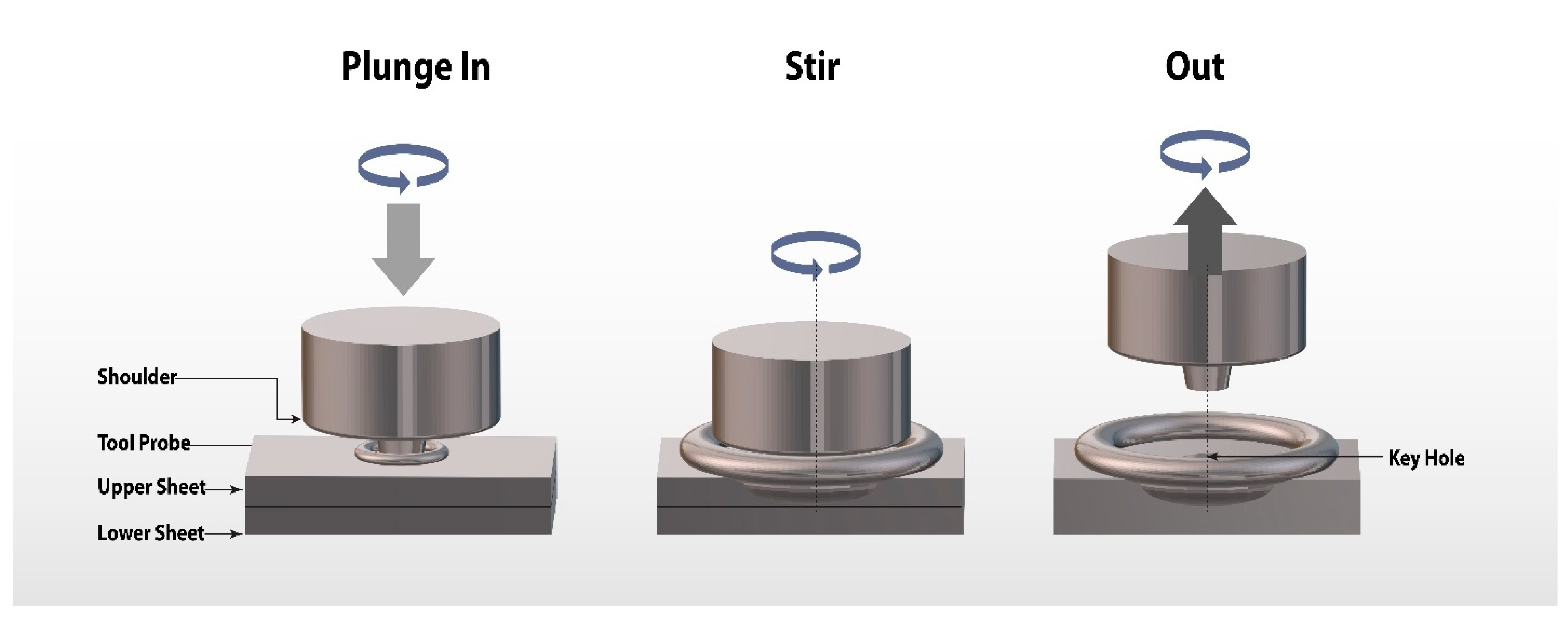
Figure 1. Schematic representation of friction stir spot welding (FSSW).
Crystals 15 00755 g001
Figure 2. A schematic of the different stages of the friction stir spot welding process.
Crystals 15 00755 g002
Figure 3. A schematic diagram of the FSSW tool.
Crystals 15 00755 g003
Figure 4. (a) Cylindrical tools made of H13 and HCHCR-D2; (b) schematic of the tool [75].
Crystals 15 00755 g004
Figure 5. Evolution of the design of PCBN tool: (a) early featureless design, (b) step spiral probe, and (c) convex scrolled shoulder step spiral probe [106].
Crystals 15 00755 g005
Figure 6. Temperature variation at different dwell times [108,109].
Crystals 15 00755 g006
Figure 7. Temperature at different plunging speeds [71,110].
Crystals 15 00755 g007
Figure 8. Comparison of experimental and numerical temperature results at different locations [114].
Crystals 15 00755 g008
Figure 9. Displacement of the joint at different tensile shear loads [71,110,117].
Crystals 15 00755 g009
Figure 10. Residual stress distribution in Al−Cu dissimilar FSSW joint (a,c) Longitudinal, (b,d) Transverse for two different locations [122].
Crystals 15 00755 g010
Figure 11. Microhardness analysis of different aluminum alloys [117,118,119,120].
Crystals 15 00755 g011
Figure 12. (A) Cross section of the FSW joint; (B) micrographs of (a) BM, (b) HAZ, (c) TMAZ; (C) micrograph of the (ac) marked regions of the Stir Nugget Zone [133].
Crystals 15 00755 g012
Figure 13. Macrographs of a typical FSpW connection cross section showing the weld zones, geometric/metallurgical features, and weld defects [132].
Crystals 15 00755 g013
Figure 14. Grain structures in joints at different tool rotational speeds [110]. (a) SZ-900 rpm, (b) TMAZ-900 rpm.
Crystals 15 00755 g014
Figure 15. Fracture surface of tensile specimen [49]: (a) as welded at a welding speed of 8 mm/min, (b) heat treated and at a welding speed of 8 mm/min.
Crystals 15 00755 g015
Figure 16. EDS images of Al-Cu joint: (a) joint interface (be), mapping of Mg, Cu, Al, and Mg-Cu-Al, (f) line scan of Al-Cu joint interface, (g) magnified joint interface, (h) various locations of the joint interface using HAADF-STEM, (il) XRD of the joint interface at various angles [121].
Crystals 15 00755 g016
Figure 17. TEM images of Stir Zone (AZ91D and Al-7Si) at different tool rotational speeds (a) 700, (b) 800, (c) 900, and (d) 1000 rpm [25].
Crystals 15 00755 g017
Table 1. Different types of steel tools used for different materials of joining.
Materials for JoiningThickness of the Joined MaterialTool Material
6061-T6 Al and AISI 1018 mild steel [17,21,64]6 mmH13
AA2011 and AA6063 alloy [13,65,66]10 mmHSS
AA5083-H111 Al alloy [67] HCHCr
AA6082 and AA2024 [26,68]4 mmC40
Commercial grade Al alloys [69]6 mmSS310
AA5754 and C11000 copper [70,71]3.175 mmH13
Table 2. Composition of tool materials [75,76,77,78].
Steel Type%C%Ni%Mn%Cr%Si%Mo%W%Cu%V
H130.450.300.505.251.201.75-0.251.20
HCHCr-D21.5 0.4512.000.300.9- 1.00
C400.37–0.440.40.5–0.80.40.40.1---
HSS0.87 0.263.99 4.615.83 1.76
SS3100.2519.0–22.02.0024.0–26.01.50
Table 3. Comparative summary of design codes for aluminum spot welding.
Code/StandardRegionDesign FocusRelevant Provisions for FSSWAdvantagesLimitations
Eurocode 9 (EN 1999-1-1)EuropeStructural design of aluminum structuresAllows mechanical fastening and fusion welding; FSSW not explicitly includedComprehensive structural safety checksLacks FSSW-specific guidance; conservative assumptions for weld strength
AWS D17.3/D17.3MUSAFriction stir welding of aluminum in aerospaceCovers friction stir welding, thus indirectly applicable to FSSWAerospace-focused, high reliabilityLimited FSSW-specific joint design parameters
AS/NZS 1665Australia/New ZealandWelding of aluminum structuresPrimarily deals with fusion welding; spot weld strength limits providedSome design guidance can be extrapolatedDoes not consider solid-state welding processes like FSSW
AISC ManualUSAStructural steel/aluminum jointsNot directly applicable but useful for understanding allowable stress designWell-established engineering principlesNo mention of FSSW or aluminum-specific solid-state welding
CSA S157CanadaStrength of aluminum jointsOffers general aluminum weld joint design guidanceIncludes provisions for performance-based assessmentNo separate treatment of friction stir-based spot welding
Disclaimer/Publisher’s Note: The statements, opinions and data contained in all publications are solely those of the individual author(s) and contributor(s) and not of MDPI and/or the editor(s). MDPI and/or the editor(s) disclaim responsibility for any injury to people or property resulting from any ideas, methods, instructions or products referred to in the content.