Article

Evaluation of Corrosion Behavior of Zn–Al–Mg-Coated Steel in Corrosive Heterogeneous Soil

by
Pedro Javier Lloreda-Jurado
* and
Ernesto Chicardi
*
Departamento de Ingeniería y Ciencia de los Materiales y del Transporte, Universidad de Sevilla, Av. Camino de los Descubrimientos s/n, 41092 Sevilla, Spain
*
Authors to whom correspondence should be addressed.
Crystals 2025, 15(8), 738; https://doi.org/10.3390/cryst15080738
Submission received: 28 June 2025 / Revised: 19 July 2025 / Accepted: 28 July 2025 / Published: 20 August 2025

Abstract

The long-term durability of steel structures in contact with soil remains a critical challenge due to the complex and aggressive nature of many soil environments. This study presents a thorough evaluation of the corrosion resistance and microstructural evolution of Magnelis® ZM430-coated steel exposed to highly aggressive, heterogeneous soils. Gravimetric analysis revealed that the Magnelis® ZM430 coating exhibits low corrosion rates and enhanced initial barrier properties, even under severe soil conditions. Although the literature frequently reports that Zn–Al–Mg coatings outperform conventional hot-dip galvanized coatings, our results highlight that this superiority is not universal and may be limited under highly aggressive, heterogeneous soils. Microstructural characterization by optical microscopy, SEM/EDS, and XRD demonstrated that the as-received coating consists of a homogeneous layer with well-distributed Zn-, MgZn2-, and Al-rich phases. Upon soil exposure, corrosion preferentially initiates in the Mg- and Al-rich interdendritic and eutectic regions, leading to selective phase depletion and localized breakdown of the protective layer. Despite these localized vulnerabilities, the overall performance of Magnelis® ZM430 remains superior, especially during the early stages of exposure. While no direct comparisons were performed in this work, our findings align with previous literature reporting superior performance of Zn–Al–Mg coatings compared to conventional hot-dip galvanized coatings in similar environments. Importantly, the integration of precise corrosion rate data with detailed soil characterization enables accurate prediction of coating service life, allowing for optimized coating thickness selection and proactive maintenance planning. These findings underscore the value of combining advanced Zn–Al–Mg coatings with site-specific environmental assessment to ensure the long-term integrity of buried steel infrastructure.

1. Introduction

Steel is widely used as a structural material in many engineering applications due to its excellent mechanical properties and cost-effectiveness. However, when steel components are installed in outdoor environments, they are susceptible to corrosion processes that can significantly reduce their service life and compromise structural integrity. In contrast to atmospheric corrosion [1], which is well-documented and understood in humid [2], saline [3,4], and polluted regions [5], soil corrosion remains a more complex and less predictable phenomenon. This is due to the combined effects of physical, chemical, and biological parameters, such as composition, porosity, galvanic potential, aeration, pH, moisture, ionic species, electrical resistivity, or microbiological activity [6,7,8,9,10], among others. This multifactorial nature makes both the prediction and prevention of corrosion particularly challenging due to the lack of universally standardized methods and comprehensive, reliable data on soil corrosivity [11]. Although certain laboratory protocols and field measurement techniques exist [12], they are often limited in scope, tailored to specific conditions, or yield results that vary significantly depending on local soil characteristics. This uncertainty is especially critical in infrastructure such as solar power plants, underground pipelines [13,14,15], electrical transmission towers [16,17], or railway systems [18].
To address these challenges and improve the durability of steel structures exposed to soil environments, a variety of protective coatings have been developed to act as barriers against corrosive agents. The most common solutions include anticorrosive paints [19], epoxy coatings [20], zinc galvanizing [21,22], or other inorganic coatings containing zinc and aluminum alloys. Although each of these systems has specific advantages depending on the application, zinc galvanizing has traditionally been favored for outdoor and buried steel due to its cost-effectiveness and ease of use. Nevertheless, recent advances have shown that Zn–Al–Mg alloy coatings significantly outperform these conventional systems in terms of corrosion resistance, particularly in atmospheric and saline environments, where their performance has been extensively studied [23,24,25], offering extended service life and reduced maintenance requirements.
The unique composition of Zn–Al–Mg coatings enables the formation of a dense, adherent, and self-healing protective layer that delivers superior long-term protection and effectively inhibits corrosion at damaged or cut edges—areas where traditional coatings are most vulnerable. This corrosion resistance is primarily attributed to the synergistic effects of aluminum and magnesium, which promote the formation of stable oxide layers and inhibit localized corrosion [26]. As a result, Zn–Al–Mg coatings are considered highly promising for steel structures exposed to the most demanding soil environments. However, despite their growing use in various structural applications, there remains a need for comprehensive evaluation of their corrosion behavior under different soil conditions. Such studies are essential to fully understand the long-term durability of these coatings and to establish reliable design and maintenance guidelines for steel structures in buried or partially buried conditions. It is crucial to note that all these factors, together with the inherent heterogeneity of soil, enable the formation of both micro- and macro-galvanic cells, leading to heterogeneous corrosion of the coating [27]. This phenomenon is one of the main reasons why the performance of the Zn–Al–Mg coatings layer in soil is not as consistent as in atmospheric conditions, since soil is a highly heterogeneous environment, unlike the atmosphere—except in cases where localized deposition of corrosive agents occurs, such as under salt spray exposure. Therefore, this work focuses on the evaluation of the corrosion resistance of Zn–Al–Mg coated steel profiles subjected to soil exposure. Through field testing, this study aims to provide insight into the protective performance of these coatings and their suitability for use in soil environments, contributing to the advancement of corrosion protection strategies for structural steel.

2. Materials and Methods

2.1. Materials: Steel Specimens and Soil Samples

The steel specimens analyzed in this study correspond to fragments of piles similar to those used in various structures and constructions, such as photovoltaic plants or electrical transmission towers. These fragments are parallelepiped-shaped samples measuring approximately 40 × 50 × 5 mm, made of structural steel coated with Magnelis® ZM430 (ArcelorMittal, Avilés, Spain), a product developed and manufactured by ArcelorMittal through continuous hot-dip galvanizing. This coating is applied by continuous hot-dip galvanizing. It consists of a metallic alloy composed of 93.5 wt.% zinc, 3.5 wt.% aluminum, and 3 wt.% magnesium, applied to both sides of the steel substrate with a thickness of approximately 35 μm/side. The lateral uncoated surfaces generated during cutting of the samples were masked with acrylic paint to avoid their oxidation.
Soil sub-samples were collected from multiple locations within a large photovoltaic solar project site located in the coastal region of southern Europe. This site was selected because it represents one of the most extreme and variable real-world environmental conditions, characterized by saline aerosols, high humidity, fluctuating temperatures, and complex soil chemistry. Soils vary considerably even within a single project site, due to factors such as microclimate, soil composition, and local contamination, all of which can significantly affect corrosion processes. To capture this inherent spatial variability, samples from distinct points were thoroughly and uniformly mixed into a single representative specimen for analysis. The soil sample was kindly provided by the company managing the site, enabling a realistic and relevant assessment of the coated steel’s performance under severe environmental stress typical of large coastal photovoltaic installations. It exhibits heterogeneous values of 0.50 to 20.8 ppm of chlorides, 400 to 16,000 ppm of SO4, 0.5 to 2.5 Ω of electrical resistivity, pH between 6.6 and 8.7, moisture between 13 and 55% at ground level and 89% and 282% at a depth of 3.5 m below ground level, and a 90th percentile around 1 mm, suggesting a high percentage of fine particles, as main parameters. These values were obtained from laboratory analyses and geotechnical reports, and are consistent with the observed presence of peat, mud, marsh soil, high organic carbon content, fuel ash, slag, coal and coke fragments, refuse, rubble, and wastewater. The combination of these factors results in a complex, spatially variable, and highly aggressive environment for buried metallic structures. Thus, its aggressiveness towards metallic materials is qualitatively classified as a “Strongly Aggressive soil”, with a high probability of wide and deep corrosion attack, and with “very strong anodic and cathodic regions”, following the guidelines of the DIN 50929-3:2018-03 standard (“Corrosion likelihood of metallic materials when subject to corrosion from the outside—Part 3: Buried and underwater pipelines and structural components”) [28]. In addition, according to this classification, following the same standard, a theoretical removal rate of the material equal to 0.2 mm/year and a penetration corrosion rate of 1 mm/year, with predominantly localized corrosion are expected. Therefore, the soil’s corrosivity classification, determined by these parameters, confirms the challenging environment for buried metallic structures.

2.2. Corrosion Testing Method

The methodology was designed to replicate under controlled laboratory conditions, as closely as possible, the actual conditions experienced by the piles in the field. Prior to burial, the samples were cleaned, dried, and accurately weighed using an analytical balance to obtain their initial mass. Then, the prepared specimens were buried in soil samples previously collected. The soil was placed in laboratory containers to maintain the natural moisture content and compaction observed in situ. The burial depth and orientation of the specimens were selected to replicate the real installation conditions of the piles.
The specimens remained buried for a predetermined period (10, 20, 30, and 40 days), allowing sufficient time for corrosion processes to occur under conditions similar to those in the field. Throughout the exposure, environmental parameters, such as temperature and humidity, were monitored to ensure consistency with the site conditions.

2.3. Characterization

A comprehensive microstructural characterization was performed on both corroded and non-corroded sections of the structural steel coated with Magnelis® ZM430. The objective was to elucidate the degradation mechanisms affecting the coating and the underlying steel substrate after burial in highly aggressive soil. This multi-technique approach—combining optical microscopy (OM) (Nikon Eclipse, Tokyo, Japan), scanning electron microscopy (SEM) (FEI Teneo, Hillsboro, Oregon, USA), energy-dispersive X-ray spectroscopy (EDS) (Oxford Instruments, Abingdon, UK), and X-ray diffraction (XRD) (Bruker, Billerica, MA, USA)—enabled a detailed examination of the corrosion processes involved, offering valuable insights into the performance of buried steel specimens.

2.3.1. Gravimetric Determination of Corrosion Rates

To experimentally determine the corrosion rate of the buried samples, a gravimetric analysis was conducted using the specimens exposed to the soil environment. The as-received samples were immersed in the soils and collected after 10, 20, 30, and 40 days. The corrosion products were removed from the surface by ultrasonic cleaning and soft brushing, the acrylic paint was removed with acetone, the specimens were dried, and then the weight was measured to determine the weight loss due to the corrosion process. The gravimetric corrosion rate was calculated for the Zn–Al–Mg metallic coating, not the bare steel. The process was repeated if necessary to ensure the complete removal of corrosion products from the coated surfaces. To ensure statistical reliability and the representativeness of the results, each burial test was performed in 8 independent replicates for every exposure period, as detailed in Table 1. This approach allowed for the minimization of experimental variability and provided robust data for calculation of corrosion rates throughout Expression (1), described in ASTM G1-03 (2017) “Standard Practice for Preparing, Cleaning, and Evaluating Corrosion Test Specimens” [29] and widely used in corrosion studies [30].
C o r r o s i o n   R a t e μ m y e a r = m n o n c o r r o d e d g m c o r r o d e d g A s a m p l e ( μ m 2 ) · t y e a r · ρ s a m p l e ( g / μ m 3 )
where mnon-corroded − mcorroded is the weight loss, Asample is the exposed surface for corrosion (based on the L1 × L2 dimensions listed in Table 1), t is the time of exposure, and ρsample is the density of the samples.

2.3.2. Direct Observation and Optical Microscopy

To determine the degree of corrosion that occurred in the buried samples, firstly, it is necessary to study the microstructure of the non-corroded Magnelis® ZM430 coating. The samples, shaped as parallelepipeds, were sectioned transversely and mounted in epoxy resin. Subsequently, they were polished using abrasive suspensions with 1 μm alumina particles until a mirror-like surface finish was achieved.
Optical microscopy was performed on these cross-sections using an Eclipse MA100N optical microscope (Nikon, Leuven, Belgium) under bright-field illumination. Magnifications ranging from 100× to 1000× were employed to capture detailed images of the coating’s microstructure. In addition, macroscopic observations of the samples were documented using a digital camera to complement the microscopic analysis.

2.3.3. X-Ray Diffraction

In order to characterize the phase evolution of the sample coating, X-ray diffraction (XRD) patterns were obtained using a D8 Advance A25 (Bruker) diffractometer by scanning 2θ values ranging from 20° to 80° in step-scan mode with increments of 0.03° and a counting time of 5 s per step to ensure sufficient phase resolution.

2.3.4. Scanning Electron Microscopy and Energy Dispersive X-Ray Spectroscopy

To complement the optical microscopy analysis and obtain high-resolution information on the surface and cross-sectional morphology of the coating and corrosion products, scanning electron microscopy (SEM) was performed using a TENEO SEM microscope (FEI, Hillsboro, OR, USA). The samples, previously mounted and polished for cross-sectional analysis, were subsequently demounted, cleaned, and carbon-coated to ensure electrical conductivity and minimize charging effects during imaging. SEM observations were carried out under high vacuum conditions with an accelerating voltage optimized at 20 kV. Both secondary electron (SE) and backscattered electron (BSE) modes were employed to reveal topographical and compositional variations across the Magnelis® ZM430 coating and the underlying steel substrate. Additionally, elemental analysis was conducted through energy-dispersive X-ray spectroscopy (EDS), integrated into the SEM system. Spot analyses, line scans, and elemental mapping were performed to determine the distribution of key elements, such as zinc, aluminum, magnesium, oxygen, and iron, in both corroded and non-corroded regions.
This allowed for a deeper understanding of the corrosion mechanisms and the protective behavior of the Zn–Al–Mg alloy layer by comparing its evolution before and after soil exposure.

3. Results and Discussion

Multiple characterization techniques (including optical microscopy, XRD, SEM, and EDS) were systematically applied to both non-corroded and corroded sections of the Magnelis® ZM430-coated steel samples. This comprehensive analysis enabled a detailed assessment of the initial microstructure, composition, and coating thickness prior to burial, serving as a reference for evaluating the morphological and chemical changes induced by progressive exposure to the highly aggressive soil environment. By contrasting the pristine and deteriorated states of the material, the following results and discussion provide insight into the evolution of the protective coating and the underlying steel, highlighting the key degradation processes and their implications for long-term pile durability.

3.1. Corrosion Rate in Soil

The corrosion rate was calculated gravimetrically, based on the difference between the initial and final mass of each specimen, the exposed surface area, and the duration of the test. This method provides a direct measurement of material loss attributable to corrosion processes during burial.
Table 1 presents the corrosion rates calculated for steel samples coated with Magnelis® ZM430 and buried in aggressive soil for periods ranging from 10 to 40 days. The results show considerable variability in corrosion rates, even among samples subjected to identical burial durations, with corrosion rate values varying from 55 to 206 units. This dispersion is attributed to the abovementioned soil heterogeneity (DIN 50929-3:2018-03), characterized by the presence of peat, ash, coal, and industrial residues, which promote the formation of galvanic macro- and micro-cells. These macro-cells induce localized differences in aeration, moisture, pH, electrical resistivity, and ionic composition, accelerating corrosion in specific anodic zones, which underscores the strong influence of local soil heterogeneity on corrosion processes.
The corrosion rate values have also been statistically analyzed, with the mean and sample standard deviation for each burial period presented in Figure 1 to further quantify and understand the variability of corrosion rates over time. At the initial 10-day exposure period, the corrosion rates generally fall between 47 and 102 μm/year, reflecting the early-stage degradation of the protective coating. As the exposure time increases to 20, 30, and 40 days, the average corrosion rate rises, reaching up to an average value of 165 μm/year at 40 days. This escalation indicates progressive breakdown of the coating, probably due to the different degradation grades of the different phases in the Magnelis® coating, and also exposure of the underlying steel substrate to the corrosive environment.
Figure 1 clearly illustrates the trend followed by the average corrosion rate, represented by a red line, which fits remarkably well to a power law model as described by Expression (2). This mathematical expression demonstrates a good agreement with the experimental data, as evidenced by a low reduced chi-square value (χ2 = 0.0509) and a high coefficient of determination (R2 = 0.97665), thereby confirming the robustness and reliability of the model. This approach is generally supported by classical studies such as those by Romanoff [31] and, later, by Matsushima [32] and Itoh [33], who report that corrosion attack rates in soil environments tend to decelerate over time, commonly following a power law. Our corrosion testing results show that the corrosion rate increases during most of the analyzed period; however, towards the end, the rate changes very little, with only a 3% variation over the last 10 days. This suggests that the corrosion process is approaching a nearly steady-state or stabilized condition. These findings indicate that while the system has not exhibited clear deceleration earlier, it is tending towards a stationary corrosion rate, consistent with the literature over longer timescales. Variations in environmental conditions, material properties, or localized corrosion mechanisms may influence this behavior. In fact, both the constants multiplying time and the exponent in this model are highly influenced by the specific characteristics of the soil, further highlighting the critical role of localized environmental conditions in shaping corrosion behavior.
C o r r o s i o n   R a t e μ m y e a r = 15.8327 · D a y s 0.6435
The good fit between the experimental data and the theoretical power law model enables reliable prediction of corrosion process evolution and helps identify when the rate effectively stabilizes. Although the corrosion rate increases with time, the sublinear exponent (less than one) indicates a progressive decrease in acceleration, eventually approaching a nearly constant rate. This behavior is typically linked to the formation of protective corrosion product layers or the depletion of the material’s most reactive phases. To define when the rate can be considered stable, a threshold of less than 0.1% relative daily increase was established. Based on this criterion, the corrosion rate becomes practically constant after approximately 1.76 years, beyond which further increases are negligible from an engineering standpoint.
Within the 40-day experimental window, the corrosion rate showed signs of stabilization, with minimal variation (only 3% over the last 10 days), indicating that a quasi-steady state had been reached. Therefore, for techniques such as EDX, XRD, and microscopy, the analysis focused on comparing the uncorroded sample with the one exposed for 40 days, as earlier time points did not yet reflect corrosion features representative of the stabilized stage. This comparison offers relevant insight into corrosion mechanisms and product composition under near-equilibrium conditions.

3.2. Microstructural and Phase Evolution

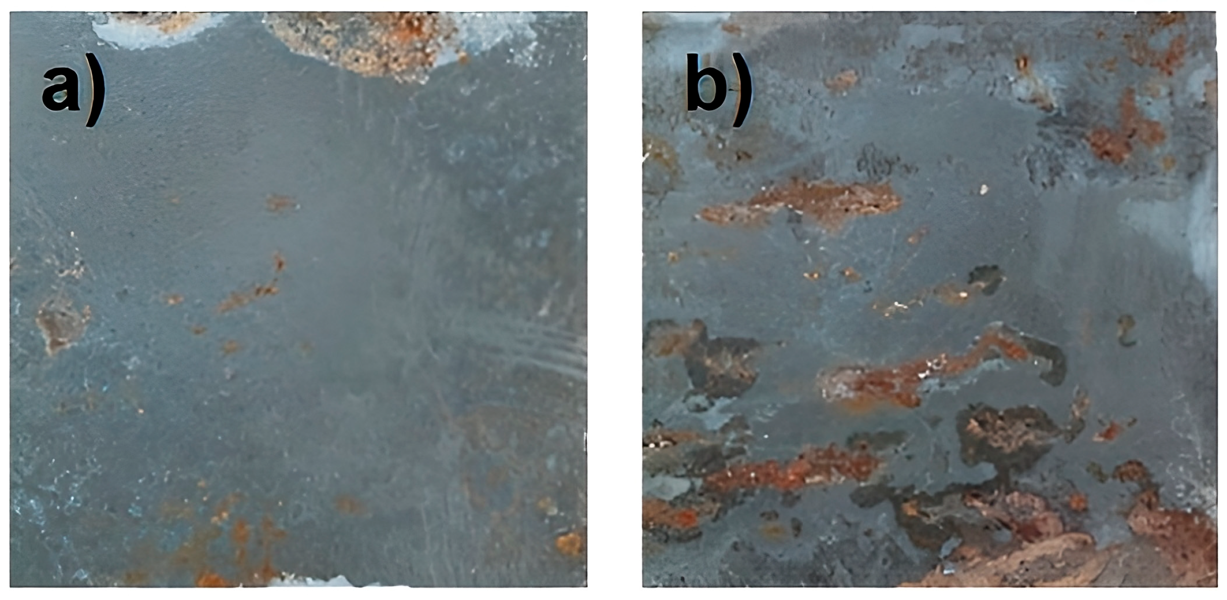
Corrosion becomes clearly evident after 30 days of exposure and is even more pronounced in samples buried for 40 days (see Figure 2). Therefore, the microstructural evolution of the Magnelis® ZM430 coating was systematically investigated to understand the degradation mechanisms in detail. Optical microscopy (OM), scanning electron microscopy (SEM), energy-dispersive X-ray spectroscopy (EDS), and X-ray diffraction (XRD) were employed to compare the coating before and after soil exposure. These techniques revealed substantial damage induced by the aggressive soil environment, aligning with the high corrosion rates previously measured.
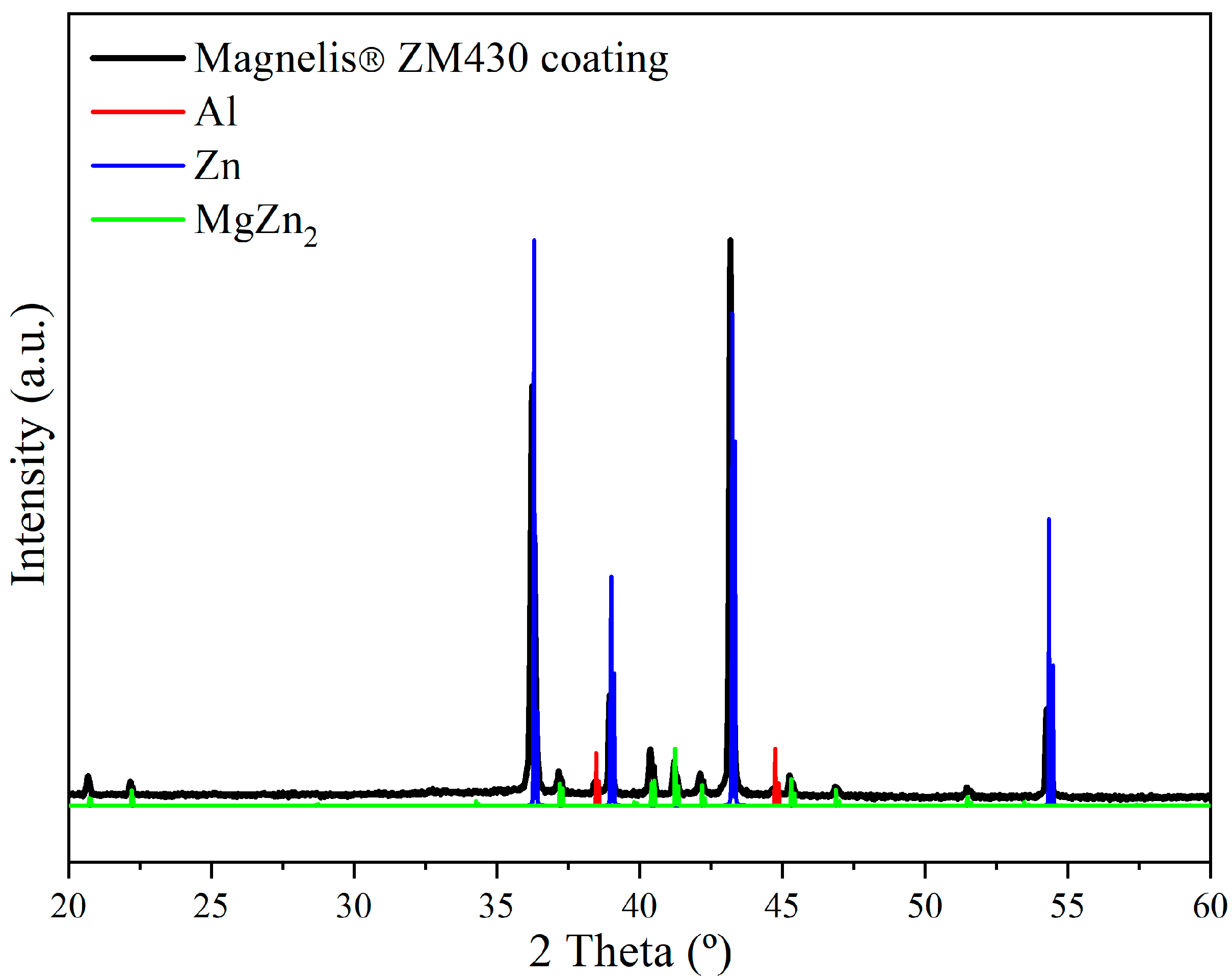
First, to ensure meaningful comparisons, the initial conditions of the non-corroded coating had to be thoroughly characterized. X-ray diffraction (XRD) analysis of the coated sample surfaces (see Figure 3) revealed the presence of three principal phases within the Magnelis® layer, concretely, metallic Zn (ref. pattern no. 004-0831 in the PDF4+ database), the intermetallic compound MgZn2 (ref. pattern no. 034-0457 in the PDF4+ database), and metallic Al (ref. pattern no. 004-0787 in the PDF4+ database). This phase assemblage is consistent with the nominal composition of the coating (93.5 wt.% Zn, 3.5 wt.% Al, 3 wt.% Mg) and with previous microstructural studies on Zn–Al–Mg alloys [34].
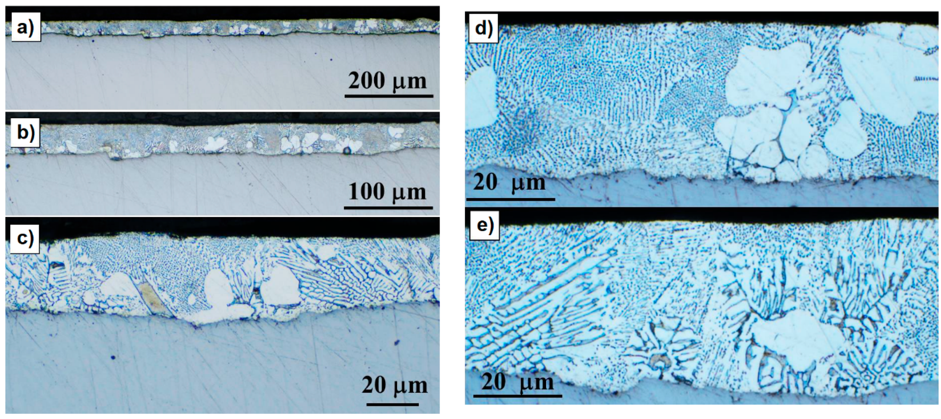
These XRD findings are further supported by the optical micrographs presented in Figure 4, which provide a clear visualization of the Magnelis® ZM430 coating’s cross-sectional structure at increasing magnifications. At lower magnifications (Figure 4a,b), the coating appears as a continuous, uniform layer with sharp contrast against the steel substrate, confirming the absence of significant porosity or defects in the untested state. Image analysis confirms a consistent average thickness of 35.7 ± 2.4 μm, closely matching the nominal 35 μm per side specified by the manufacturer.
At higher magnifications (Figure 4c–e), the internal microstructure of the coating is revealed in greater detail, and the internal heterogeneity of the Magnelis® ZM430 coating becomes evident. The images show a well-organized dendritic morphology, where large primary Zn-rich dendrites are embedded in a finer interdendritic matrix. This matrix corresponds to the eutectic regions enriched in Mg and Al, as previously reported for Zn–Al–Mg coatings [34,35]. The clear distinction between these microstructural features supports the phase identification obtained by XRD, indicating that the Zn-rich dendrites, MgZn2 intermetallics, and Al-rich phases are not only present but also well distributed throughout the coating. The highest magnification images (Figure 4d,e) allow for the identification of these microstructural features, displaying a network of secondary phases distributed between the primary dendrites. The clear delineation between the coating and the steel substrate, together with the uniformity of the layer, suggests effective metallurgical bonding and optimal process control during the hot-dip galvanizing operation, which supports the initial corrosion resistance of the system and serves as a critical reference for assessing subsequent degradation mechanisms after soil exposure.
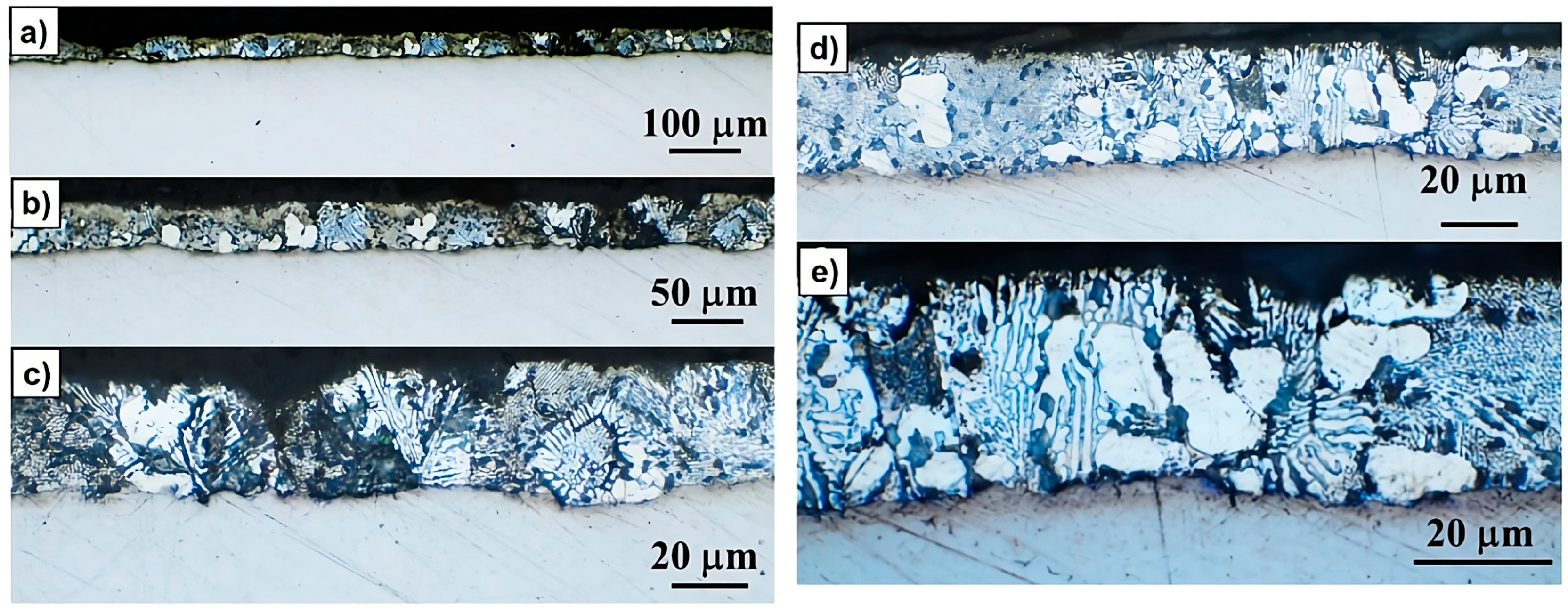
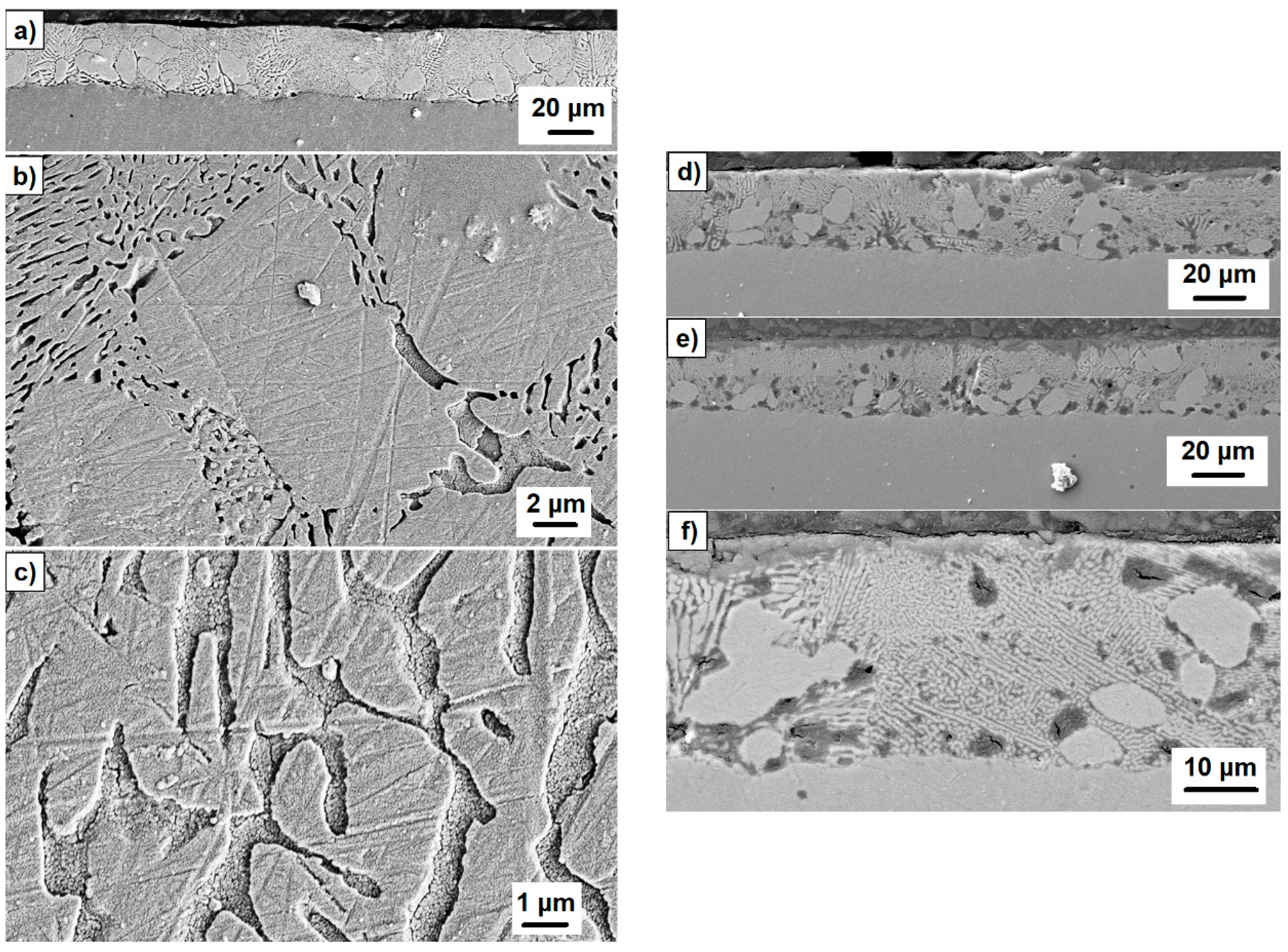
In contrast, corroded samples subjected to 40 days of soil exposition show significant coating degradation, with average residual thickness reduced to 33.7 ± 1.7 μm and, in some areas, complete loss of the protective layer, also corroborating the loss of thickness for the protective coating layer due to corrosion. However, it should be noted that this average value represents only the maximum thicknesses measured in selected regions observed as optical microscopy images (Figure 5a–d). Meanwhile, extensive deterioration and damage extend throughout the entire thickness of the coating. Therefore, even if some residual coating remains, it no longer provides any effective protection to the underlying steel, rendering the layer functionally useless.
The same microstructure was observed in the SEM images. Figure 6 shows the electron scanning micrographs, comparing the cross-sectional morphology of the Magnelis® ZM430 coating in non-corroded (Figure 6a–c) and corroded (Figure 6d–f) samples. In the non-corroded samples, the coating appears continuous and uniform, with a well-defined dendritic structure and clear separation from the steel substrate, reflecting the integrity and protective quality of the original layer. In contrast, the corroded samples after 40 days of burial display substantial degradation: the coating is thinner, less uniform, and shows visible discontinuities and damage throughout its thickness. Higher magnification images reveal the loss of the characteristic lamellae area, the presence of corrosion products, and areas where the protective layer is almost entirely consumed.
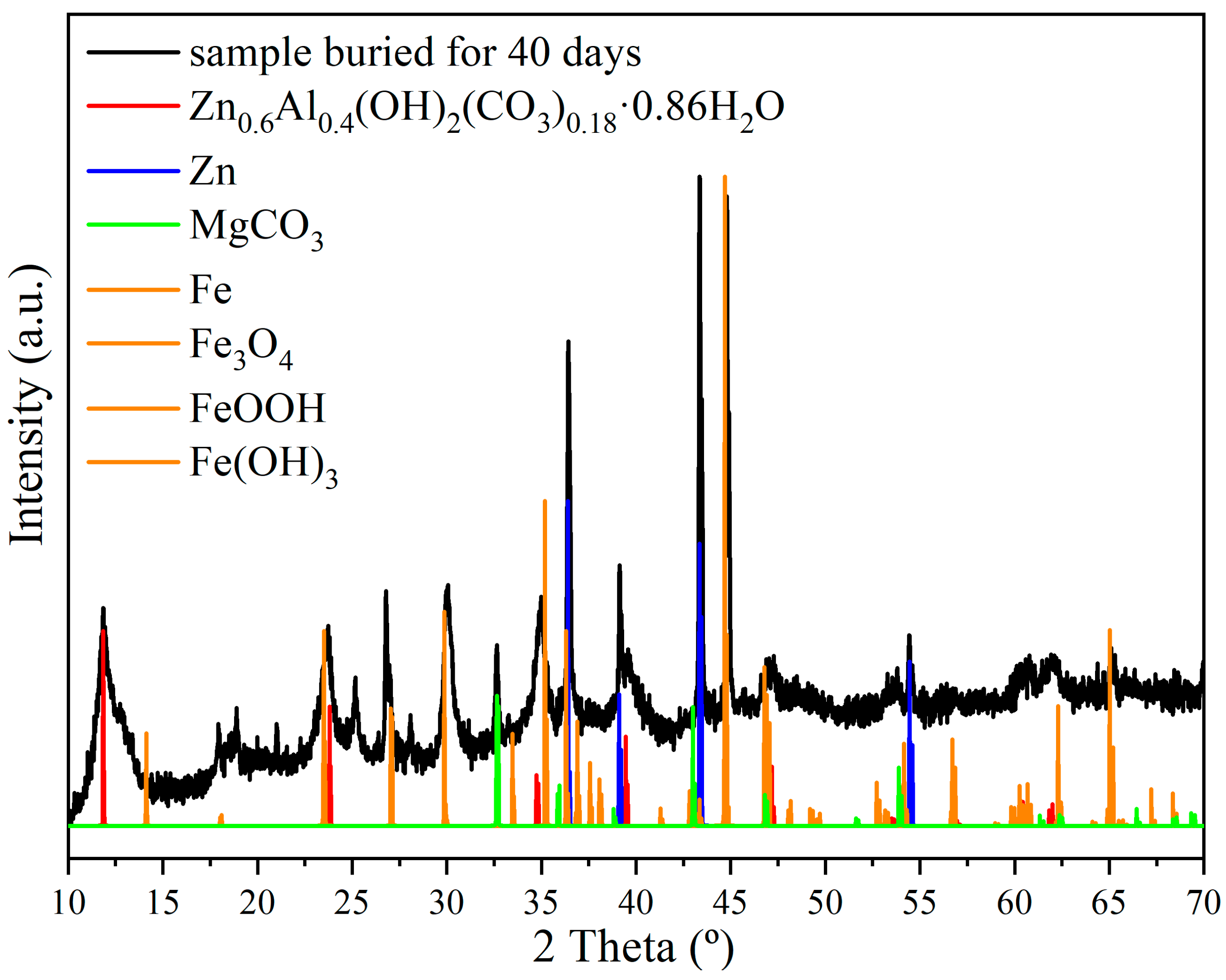
In addition, XRD (Figure 7) and EDS analyses (Figure 8 and Figure 9) further confirm the preferential dissolution of MgZn2 and Al phases, aligned with their higher electrochemical potentials, and the formation of secondary corrosion products, such as Zn-Al carbonates, Mg carbonates and Al-Mg silicates. However, the most important sighting is the detection of iron, coming from the structural carbon steel metal, and steel corrosion products, such as iron oxides and iron oxide-hydroxides, corroborating that the corrosion surpassed the protective layer, reaching the base metal steel substrate. This indicates localized coating failure and partial exposure of the steel substrate, with incomplete removal of the coating. The detection of metallic iron reflects local breaches, while most of the coating and its corrosion products continue to protect the surface. Indeed, samples buried for longer periods, such as 40 days, retained greater amounts of adhering soil in specific areas even after cleaning, which suggests stronger soil–metal interactions and greater heterogeneity in corrosion mechanisms. This aggressive soil environment, as quantified by the DIN 50929-3:2018-03 standard parameters, is a key factor in the accelerated corrosion and premature degradation observed in the samples.
In samples buried for 40 days, corrosion is present on the surface of the samples. Thus, with XRD (Figure 7), the presence of the primary metallic Zn was clearly detected. On the other hand, there are no peaks corresponding to the original phases from the Magnelis® ZM430 coating, i.e., the intermetallic MgZn2 and the metallic Al. This aspect suggests a preferential oxidation of both MgZn2 and Al, at least when the anodic and cathodic are presented in the buried samples, such as takes place in this case. This assertion is corroborated in the oxidation electrochemical potential of different phases, being E°(Zn) = +0.76 V; E°(MgZn2) = +1.40 V [36]; E°(Al) = +1.66 V; E°(Mg) = +2.37 V. With those values, it is accepted that the preferential oxidation of Al and MgZn2 (due to the presence of Mg) comes from the ternary and binary eutectic area. Such a microstructure, characterized by a combination of Zn-rich dendrites and interdendritic MgZn2/Al-rich regions, is known to enhance corrosion resistance through a synergistic effect. The Zn matrix provides sacrificial protection, while the Mg and Al phases contribute to the formation of stable and adherent corrosion products, as described in the literature [34]. This preferential oxidation has been already previously reported [35]. In fact, in the presence of the highly corrosive soils with macro-cells, as it is in this case, the presence of different phases with different oxidation electrochemical potential also creates also microcells, favoring the preferential corrosion of some phases. This preferential corrosion is also corroborated by the observation of the sample with the optical microscope (Figure 4 and Figure 5). There, a great level of corrosion was observed, with preferential corrosion of the lamellae area corresponding to the Zn/MgZn2/Al and the Zn/MgZn2 ternary and binary eutectic area, respectively.
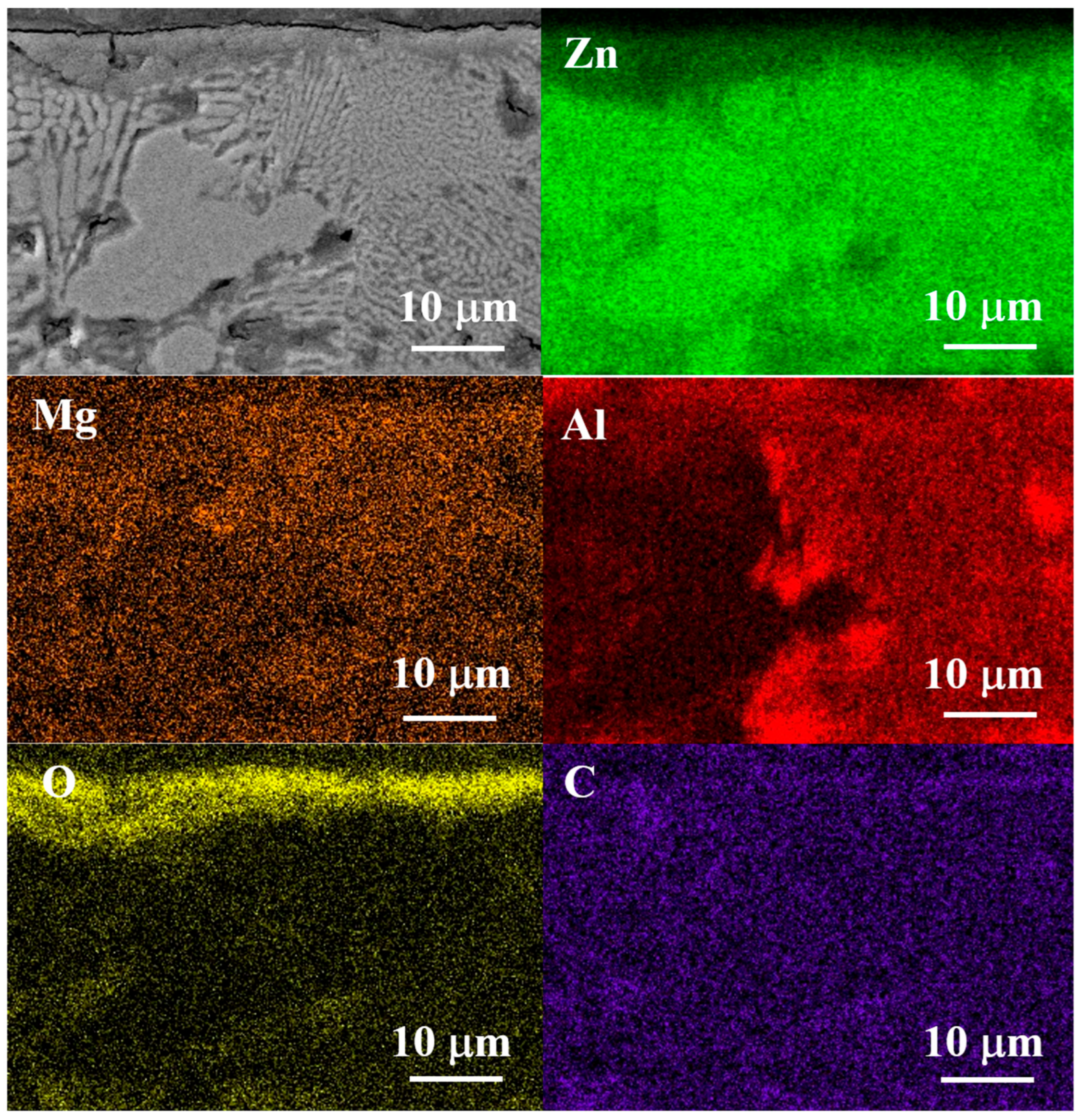
Lastly, an EDS analysis coupled with SEM was employed to perform cross-sectional elemental mapping of the Magnelis® ZM430 coating, as shown Figure 8 and Figure 9. Comparing the as-received state (Figure 8) and the sample after 40 days of burial in aggressive soil (Figure 9) reveals pronounced changes in the elemental distribution. In the initial condition, the dendritic bright phase corresponds to primary solidified Zn, while the finer lamellar regions are composed of a binary eutectic of MgZn2 and Zn, as well as a ternary eutectic phase containing lamellae of MgZn2, Zn, and Al-rich nodules [35,37]. These features are characteristic of Zn–Al–Mg coatings produced by hot-dip galvanizing and account for their initial corrosion resistance. After 40 days of soil exposure, the elemental maps reveal a clear depletion of Mg and Al in the interdendritic and eutectic regions, indicating that these areas are preferentially attacked during corrosion. This selective dissolution of the MgZn2 and Al-rich phases leads to the formation of porous corrosion products and leaves the Zn-rich dendrites more exposed. The loss of these electrochemically active phases compromises the protective performance of the coating, accelerating the progression of corrosion towards the steel substrate.
The advanced corrosion state observed after 40 days confirms that degradation initiates in the ternary eutectic regions, especially those containing Al-rich nodules, as these phases possess higher oxidation potentials and act as local anodes [35]. Cracks observed in these areas (Figure 5 and Figure 6d–f) are attributed to volume changes associated with the oxidation of Al and MgZn2. This microgalvanic coupling between anodic (eutectic) and cathodic (Zn dendrite) regions underlies the insidious corrosion mechanism of the Magnelis® ZM430 coating. Additionally, magnesium oxide (MgO) was detected in some surface regions (Figure 7, Figure 8 and Figure 9). However, MgO does not provide lasting passivation, as it readily transforms into magnesium hydroxide in the presence of moisture, and subsequently into magnesium carbonate (MgCO3) in CO2-rich environments, as confirmed by XRD analysis of the corroded samples. The combination of microgalvanic effects and the highly aggressive soil environment thus accelerates the overall corrosion process, leading to rapid and extensive degradation of the Magnelis® ZM430 coating.

4. Conclusions

This study provides a comprehensive assessment of the corrosion behavior and microstructural evolution of Magnelis® ZM430-coated structural steel when exposed to highly aggressive, heterogeneous corrosive soils. The initial characterization of the as-received Magnelis® ZM430 coating revealed a homogeneous and well-adhered microstructure, with an average thickness of approximately 35 μm per side, as confirmed by optical and electron microscopy. X-ray diffraction analysis identified metallic Zn, the intermetallic compound MgZn2, and Al-rich phases as the principal constituents of the coating, in agreement with its nominal composition and with previous literature on Zn–Al–Mg alloy systems.
Gravimetric corrosion testing under simulated field conditions demonstrated that the corrosion rate of Magnelis® ZM430-coated steel is markedly high during the initial stages of soil exposure, particularly in the highly contaminated and heterogeneous soils, according to DIN 50929-3. The corrosion rate follows a power-law decay, with rapid initial material loss that gradually decreases as corrosion products accumulate, and the most reactive phases are depleted. This behavior highlights the importance of early-stage degradation processes in determining the long-term durability of the coating.
Microstructural analysis after soil exposure revealed that corrosion preferentially initiates and propagates in the interdendritic and eutectic regions of the coating, which are rich in Mg and Al. These phases are more electrochemically active and are selectively dissolved during exposure, leading to the formation of discontinuities between the corrosion products and the eventual exposure of Zn-rich dendrites and the underlying steel substrate. SEM/EDS mapping and phase analysis confirmed the progressive depletion of Mg and Al in the coating after burial, along with the formation of secondary corrosion products such as carbonates, hydroxycarbonates, hydroxides, and oxyhydroxides. These products do not provide lasting passivation, and their formation is associated with the breakdown of the eutectic network and the loss of the coating’s protective capacity.
The aggressive nature of the studied soil—characterized by high organic content, strong anodic/cathodic effects, and significant heterogeneity—was found to accelerate localized corrosion and coating breakdown. The combination of microgalvanic and macrogalvanic coupling within the coating and the external soil environment leads to rapid and insidious degradation mechanisms that can compromise the long-term performance of buried steel structures.
In summary, the results of this study confirm that although Magnelis® ZM430 coatings offer superior corrosion resistance compared to conventional hot-dip galvanized coatings, special caution is warranted in highly heterogeneous soil environments. The microstructural analysis in tests carried out on highly aggressive and heterogeneous soil environments reveal that that galvanic cells or localized anodic and cathodic zones can readily form, leading to rapid oxidation of the anodic regions, specifically the Mg- and Al-rich interdendritic and eutectic phases. The overall performance of the Zn–Al–Mg alloy system surpasses that of traditional zinc coatings, especially in terms of initial barrier protection and self-healing capacity. Importantly, the integration of accurate corrosion rate measurements with a thorough characterization of the soil environment enables a more reliable prediction of the coating’s service life. This approach allows engineers and designers to tailor the thickness of the protective layer to the specific aggressiveness of the soil, optimizing both durability and cost-effectiveness. Moreover, such predictive knowledge makes it possible to establish preventive maintenance schedules and to anticipate the timeframe in which the coating will remain effective, thus ensuring the long-term integrity of buried steel structures. These findings highlight the value of combining advanced material solutions with site-specific environmental assessment as a strategy for sustainable infrastructure management.

Author Contributions

Conceptualization, E.C.; methodology, E.C.; formal analysis, E.C. and P.J.L.-J.; investigation, E.C. and P.J.L.-J.; resources, E.C.; writing—original draft preparation, E.C. and P.J.L.-J.; writing—review and editing, E.C. and P.J.L.-J.; supervision, E.C. and P.J.L.-J.; project administration, E.C.; funding acquisition, E.C. All authors have read and agreed to the published version of the manuscript.

Funding

This research was funded by the University of Seville in the VIIPPIT-2024-I.3—Grants for the Use of General Research Services (CITIUS).

Data Availability Statement

The data that support the findings of this study are subject to a confidentiality agreement and therefore are not publicly available. Access to these data may be granted upon reasonable request and with permission from the data owner, respecting any legal and ethical restrictions.

Acknowledgments

The authors would like to thank laboratory technician Jesús Pinto Quintana for his assistance in the experimental characterizations of the corroded specimens.

Conflicts of Interest

The authors declare no conflicts of interest.

References

  1. Morcillo, M.; Díaz, I.; Cano, H.; Chico, B.; De La Fuente, D. Atmospheric Corrosion of Weathering Steels. Overview for Engineers. Part I: Basic Concepts. Constr. Build. Mater. 2019, 213, 723–737. [Google Scholar] [CrossRef]
  2. Yang, X.; Li, Q.; Liu, S.; Hu, J.; Zhu, R.; Yang, G. Atmospheric Corrosion Prediction of Carbon Steel and Weathering Steel Based on Big Data Technology. Corros. Commun. 2025, 19, 63–75. [Google Scholar] [CrossRef]
  3. Corvo, F.; Betancourt, N.; Mendoza, A. The Influence of Airborne Salinity on the Atmospheric Corrosion of Steel. Corros. Sci. 1995, 37, 1889–1901. [Google Scholar] [CrossRef]
  4. Dalmora, G.P.V.; Borges Filho, E.P.; Maraschin Conterato, A.A.; Roso, W.S.; Pereira, C.E.; Dettmer, A. Methods of Corrosion Prevention for Steel in Marine Environments: A Review. Results Surf. Interfaces 2025, 18, 100430. [Google Scholar] [CrossRef]
  5. Santa, A.C.; Montoya, D.A.; Tamayo, J.A.; Gómez, M.A.; Castaño, J.G.; Baena, L.M. Atmospheric Corrosion of Carbon Steel: Results of One-Year Exposure in an Andean Tropical Atmosphere in Colombia. Heliyon 2024, 10, e29391. [Google Scholar] [CrossRef]
  6. Corcoran, P.; Jarvis, M.G.; Mackney, D.; Stevens, K.W. Soil Corrosiveness in South Oxfordshire. J. Soil Sci. 1977, 28, 473–484. [Google Scholar] [CrossRef]
  7. Ferreira, C.A.M.; Ponciano, J.A.C.; Vaitsman, D.S.; Pérez, D.V. Evaluation of the Corrosivity of the Soil through Its Chemical Composition. Sci. Total Environ. 2007, 388, 250–255. [Google Scholar] [CrossRef]
  8. Zhou, E.; Li, F.; Zhang, D.; Xu, D.; Li, Z.; Jia, R.; Jin, Y.; Song, H.; Li, H.; Wang, Q.; et al. Direct Microbial Electron Uptake as a Mechanism for Stainless Steel Corrosion in Aerobic Environments. Water Res. 2022, 219, 118553. [Google Scholar] [CrossRef] [PubMed]
  9. Nguyen Dang, D.; Lanarde, L.; Jeannin, M.; Sabot, R.; Refait, P. Influence of Soil Moisture on the Residual Corrosion Rates of Buried Carbon Steel Structures under Cathodic Protection. Electrochim. Acta 2015, 176, 1410–1419. [Google Scholar] [CrossRef]
  10. Amadi, A.H.; Ajienka, J.A.; Akaranta, O.; Moses, P.R.; Achara, N.U.; Ola, V.D.; Udo, R.D. A Review of Soil Resistivity Testing for Enhanced Corrosion Control: Overcoming Limitations through Integrated Geophysical Approaches and Alternative Methodologies. Measurement 2025, 242, 116214. [Google Scholar] [CrossRef]
  11. Dong, Z.; Ding, L.; Meng, Z.; Xu, K.; Mao, Y.; Chen, X.; Ye, H.; Poursaee, A. Machine Learning-Based Corrosion Rate Prediction of Steel Embedded in Soil. Sci. Rep. 2024, 14, 18194. [Google Scholar] [CrossRef]
  12. Arriba-Rodriguez, L.; Villanueva-Balsera, J.; Ortega-Fernandez, F.; Rodriguez-Perez, F. Methods to Evaluate Corrosion in Buried Steel Structures: A Review. Metals 2018, 8, 334. [Google Scholar] [CrossRef]
  13. Ramesh Babu, J.; Karve, P.M.; Mahadevan, S. Probabilistic Prediction of External Corrosion Fatigue Life in Buried Steel Pipes. Int. J. Press. Vessel. Pip. 2025, 214, 105415. [Google Scholar] [CrossRef]
  14. Cai, Z.; Liu, Y.; Liu, X.; Zhang, J.; Li, T.; Xu, B. Prediction of Interference Current of Buried Pipeline and Study on Corrosion of Q235A Steel. Constr. Build. Mater. 2023, 400, 132739. [Google Scholar] [CrossRef]
  15. Wang, T.; Xu, D.; Qu, L.; Fu, J.; Li, Z. An Extension Approach to Estimate Soil Corrosivity for Buried Pipelines. Int. J. Press. Vessel. Pip. 2021, 192, 104413. [Google Scholar] [CrossRef]
  16. Scheffer De Matos, T.; Franke Portella, K.; Luiz Henke, S.; D’Orey Gaivão Portella Bragança, M.; Medeiros De Almeida, L. Novel Approach to Detect Encasement Failures in the Anchorage System of Guyed Transmission Towers by Distribution of Relaxation Times. Eng. Fail. Anal. 2024, 165, 108788. [Google Scholar] [CrossRef]
  17. Matos, T.S.; Portella, K.F.; Henke, S.L.; Bragança, M.O.G.P.; Galvão, M.P.; Dias, B.G.; Lagoeiro, L.; Almeida, L.M. Analysis of Anchor Rod Failure in a Guyed Transmission Tower: Influence of Microstructures and Corrosion Mechanisms. Eng. Fail. Anal. 2021, 121, 105166. [Google Scholar] [CrossRef]
  18. Vivanco, J.R.; Breul, P.; Talon, A.; Benz-Navarrete, M.A.; Barbier, S.; Haddani, Y. Importance of Geotechnical Diagnosis in Railway Management: A Review. Transp. Eng. 2024, 18, 100293. [Google Scholar] [CrossRef]
  19. Sørensen, P.A.; Kiil, S.; Dam-Johansen, K.; Weinell, C.E. Anticorrosive Coatings: A Review. J. Coat. Technol. Res. 2009, 6, 135–176. [Google Scholar] [CrossRef]
  20. Li, J.; Wang, D.; Hou, L.; Zhang, S.; Wu, P.; Zhang, Y.; Liu, B.; Wei, Y. Enhancing the Corrosion Resistance of the Epoxy Coating Using CaAl LDH Intercalated with L-Cysteine and Its Derivatives as a Pigment on Steel Substrate. Prog. Org. Coat. 2024, 193, 108527. [Google Scholar] [CrossRef]
  21. He, C.; Wang, Z.; You, Y.; Wang, X.; Zhao, P.; Yang, Z.; Zhou, L. Influence of Soil Variability on the Corrosion of Buried Hot-Dip Galvanized Steel. Int. J. Electrochem. Sci. 2025, 20, 100889. [Google Scholar] [CrossRef]
  22. Rossi, S.; Pinamonti, M.; Calovi, M. Influence of Soil Chemical Characteristics on Corrosion Behaviour of Galvanized Steel. Case Stud. Constr. Mater. 2022, 17, e01257. [Google Scholar] [CrossRef]
  23. Liu, Y.; Gu, T.; Liu, M.; Wang, Z.; Cao, G.; Guo, Q.; Wang, C. Corrosion Mechanism of a High Corrosion-Resistance Zn–Al–Mg Coating in Typical Extremely Harsh Marine and Cold Environments. J. Mater. Res. Technol. 2024, 33, 4290–4302. [Google Scholar] [CrossRef]
  24. Volovitch, P.; Vu, T.N.; Allély, C.; Abdel Aal, A.; Ogle, K. Understanding Corrosion via Corrosion Product Characterization: II. Role of Alloying Elements in Improving the Corrosion Resistance of Zn–Al–Mg Coatings on Steel. Corros. Sci. 2011, 53, 2437–2445. [Google Scholar] [CrossRef]
  25. Thierry, D.; LeBozec, N.; Le Gac, A.; Persson, D. Long-term Atmospheric Corrosion Rates of Hot Dip Galvanised Steel and Zinc-aluminium-magnesium Coated Steel. Mater. Corros. 2019, 70, 2220–2227. [Google Scholar] [CrossRef]
  26. Kim, S.-H.; Jin, S.-Y.; Yang, J.-H.; Yang, J.-H.; Lee, M.-H.; Yun, Y.-S. Self-Healing Phenomenon at the Cut Edge of Zn-Al-Mg Alloy Coated Steel in Chloride Environments. Coatings 2024, 14, 485. [Google Scholar] [CrossRef]
  27. Zhang, C.; Liao, Y.; Gao, X.; Zhao, J.; Yuan, Y.; Liao, R. Research Advances of Soil Corrosion of Grounding Grids. Micromachines 2021, 12, 513. [Google Scholar] [CrossRef]
  28. DIN 50929-3:2018-03; Corrosion of Metals—Corrosion Likelihood of Metallic Materials When Subject to Corrosion from the Outside—Part 3: Buried and Underwater Pipelines and Structural Components. Beuth: Berlin, Germany, 2018. [CrossRef]
  29. ASTM G1-03(2017); Standard Practice for Preparing, Cleaning, and Evaluating Corrosion Test Specimens. ASTM: West Conshohocken, PA, USA, 2017. [CrossRef]
  30. Iribarren, J.I.; Liesa, F.; Alemán, C.; Armelin, E. Corrosion Rate Evaluation by Gravimetric and Electrochemical Techniques Applied to the Metallic Reinforcing Structures of a Historic Building. J. Cult. Herit. 2017, 27, 153–163. [Google Scholar] [CrossRef]
  31. Romanoff, M. Underground Corrosion; National Bureau of Standards: Gaithersburg, MD, USA, 1957.
  32. Matsushima, I. Carbon Steel—Corrosion by Soils. In Uhlig’s Corrosion Handbook; Revie, R.W., Ed.; Wiley: Hoboken, NJ, USA, 2011; pp. 609–613. ISBN 978-0-470-08032-0. [Google Scholar]
  33. Itoh, M. Time-Dependent Power Laws in the Oxidation and Corrosion of Metals and Alloys. Sci. Rep. 2022, 12, 6944. [Google Scholar] [CrossRef] [PubMed]
  34. Salgueiro Azevedo, M.; Allély, C.; Ogle, K.; Volovitch, P. Corrosion Mechanisms of Zn(Mg,Al) Coated Steel: 2. The Effect of Mg and Al Alloying on the Formation and Properties of Corrosion Products in Different Electrolytes. Corros. Sci. 2015, 90, 482–490. [Google Scholar] [CrossRef]
  35. Sullivan, J.; Mehraban, S.; Elvins, J. In Situ Monitoring of the Microstructural Corrosion Mechanisms of Zinc–Magnesium–Aluminium Alloys Using Time Lapse Microscopy. Corros. Sci. 2011, 53, 2208–2215. [Google Scholar] [CrossRef]
  36. Ikeuba, A.I.; Kou, F.; Duan, H.; Zhang, B.; Wang, J.; Han, E.-H.; Ke, W. Understanding the Electrochemical Behavior of Bulk-Synthesized MgZn2 Intermetallic Compound in Aqueous NaCl Solutions as a Function of pH. J. Solid State Electrochem. 2019, 23, 1165–1177. [Google Scholar] [CrossRef]
  37. He, X.; Zhou, X.; Shang, T.; Liu, W.; Jiang, G.; Liu, C.; Cheng, X.; Zhang, X.; Li, X. Influence Mechanism of Different Elements and Alloy Phases on the Corrosion Resistance of Zn-Al-Mg Coated Steel in the Atmospheric Environment: A Review. Corros. Commun. 2024, 13, 49–59. [Google Scholar] [CrossRef]
Figure 1. Soil corrosion rate for the structural steel coated with Magnelis® ZM430, from 10 days to 40 days.
Crystals 15 00738 g001
Figure 2. Sample surfaces after corrosion testing: (a) 30 days and (b) 40 days.
Crystals 15 00738 g002
Figure 3. XRD for the non-corroded samples of the structural steel coated with Magnelis® ZM430.
Crystals 15 00738 g003
Figure 4. Optical micrographs of the cross-section of non-corroded Magnelis® ZM430 coating at different magnifications: (a) 100×, (b) 200×, (c), 500×, and (d) and (e) 1000×.
Crystals 15 00738 g004
Figure 5. Optical micrographs of the cross-section of corroded Magnelis® ZM430 coating, buried for 40 days, at different magnifications: (a) 100×, (b) 200×, (c), 500×, (d) 500×, and (e) 1000×.
Crystals 15 00738 g005
Figure 6. Electron scanning micrographs of the cross-section of Magnelis® ZM430 coating at different magnifications for (ac) non-corroded samples and (df) corroded samples after being buried for 40 days.
Crystals 15 00738 g006
Figure 7. XRD for the corroded samples of the structural steel coated with Magnelis® ZM430 buried for 40 days.
Crystals 15 00738 g007
Figure 8. Cross-sectional SEM-EDS elemental mapping of Magnelis® ZM430 coating before 40 days of burial in aggressive soil.
Crystals 15 00738 g008
Figure 9. Cross-sectional SEM-EDS elemental mapping of Magnelis® ZM430 coating after 40 days of burial in aggressive soil.
Crystals 15 00738 g009
Table 1. Characteristics of non-corroded and corroded samples employed in corrosion testing, with corresponding exposure details and measured corrosion rates.
SampleCorrosion DaysNon-Corroded SampleCorroded Sample
L1 (mm)L2 (mm)Thickness (mm)m (g)Density (g/mL)m (g)Corrosion Rate (μm/Year)
1d101039.9449.462.6341.13087.9241.086653
2d101040.0049.972.7141.58507.6841.544648
3d101039.9450.392.7041.84957.7041.7626102
4d101039.9549.572.7041.30677.7341.265249
5d101040.0649.672.7441.43047.6041.390847
6d101039.3649.572.7141.20207.7941.150862
7d101039.7340.272.7142.21037.8042.143379
8d101040.0849.912.7342.30537.7542.2188102
1d202040.4349.902.7042.01377.7141.863688
2d202040.1749.452.7141.48637.7141.430733
3d202039.9149.272.7440.91727.5940.6254175
4d202040.0249.862.7141.63057.7041.2645217
5d202039.849.392.6741.01777.8240.893675
6d202039.4850.202.6841.28937.7741.148084
7d202040.4350.002.6842.09067.7741.8823122
8d202040.4050.232.7042.37967.7342.0820173
1d303039.8149.812.7041.31677.7241.082593
2d303040.4549.812.7141.86757.6741.752345
3d303040.0850.672.7141.93187.6241.2881249
4d303039.9850.092.6941.55117.7140.9136251
5d303039.7250.262.7041.44597.6941.1886101
6d303039.8749.862.7242.11267.7941.916378
7d303039.8550.272.7242.37987.7841.8225219
8d303040.3650.362.6942.20547.7241.5805242
1d404040.2049.982.7041.72777.6941.3118122
2d404040.1149.802.7041.54847.7041.1879107
3d404040.2949.822.7141.84007.6941.0005234
4d404040.4149.472.7141.85087.7340.9799198
5d404040.4950.152.6742.28037.8041.8701119
6d404039.6749.512.7241.73047.8141.2106156
7d404039.7649.962.7341.99397.7441.2263198
8d404040.3450.152.7042.19347.7241.3657183
Disclaimer/Publisher’s Note: The statements, opinions and data contained in all publications are solely those of the individual author(s) and contributor(s) and not of MDPI and/or the editor(s). MDPI and/or the editor(s) disclaim responsibility for any injury to people or property resulting from any ideas, methods, instructions or products referred to in the content.