1. Introduction
One of the research and development interests is represented by the study of the ballistic response of armored steel plates when projectiles hit them. For military applications, the aim is to enhance the ballistic properties of armor while simultaneously reducing its weight. Thus, for the manufacture of armored vehicles, magnesium, titanium, and aluminum are among the most widely used light alloys [
1,
2,
3,
4,
5,
6,
7]. However, the primary materials used in armor manufacture are high-strength steels [
8]. These steels have high strength, ductility, hardness, ease of manufacture, and low cost [
1,
9,
10]. For this reason, researchers have studied high-strength steels to determine their ballistic properties [
9,
11,
12].
Borvik et al. investigated the ballistic performance of Armox 500T, Weldox 700E, Weldox 500E, Domex Protect 500, and Hardox 400 when subjected to 7.62 mm caliber projectiles. For the investigated thicknesses of these steels, only Armox 500T and Domex Protect 500 steels provided adequate ballistic protection; the rest require an increase in armor thickness [
9]. Iqbal et al. [
11] studied the ballistic performance of Armox 500T when impacted by 12.7 API and 7.62 mm bullets. They also studied the characterization of materials at high strain rates, including both the armor-piercing projectiles and the target material. In another study, Bernetic et al. investigated the fracture mechanisms of high-strength steel PROTAC 500 upon impact with 7.62 mm-caliber bullets [
13].
High-strength steels are increasingly used in military and civil engineering; these materials are relatively new to the field of engineering. These materials have been developed intensively since the 1990s. Nowadays, the strength of high-strength steels can be improved up to several thousand MPa through appropriate thermo-mechanical processing and alloying processes. In modern industry, there is a trend towards reducing the weight and mass of structures to improve welding processes, enhance vehicle mobility, and reduce fuel and energy consumption. Thus, the development of these steels is very common. To improve the ballistic properties of these steels, the material’s strength is being studied [
14].
Hardox 450 steel (produced in Sweden by SSAB) has high strength and hardness, which is due to certain heat treatment processes (sequential tempering and quenching). Hardox 450 steel does not require preheating to temperatures above 250 °C before welding. Also, post-weld heat treatment is not recommended for this steel. Another important feature of Hardox 450 steel is that it possesses satisfactory plasticity and toughness. Hardox 450 is used in the manufacture of surfaces that are subject to wear, particularly in parts exposed to severe abrasion. The main components made from this type of steel include high-pressure vessels, freight truck boxes, gas transport tanks, railway wagons, freight wagon bodies, supports, and legs for vehicles carrying missile launchers, among others. At the same time, HARDOX 450 steel is used in the manufacture of traps and ballistic barriers used at small arms shooting ranges, among other applications [
15,
16,
17,
18]. Thus, due to its impressive toughness, hardness, and high wear resistance, Hardox 450 steel is widely used in various industries [
19,
20]. To improve the ballistic impact properties of armor used against small arms, metallic materials like steel are coated with inert ceramics. To achieve the desired ballistic properties, the design of ceramic-coated armor considers the mechanical properties of the ceramic that enable the projectile to fracture. Ceramic-coated armor develops mechanical properties that ensure projectile fracture. These armors also feature a flexible layer that serves as a capture mechanism for damaged ceramic and projectile debris [
21].
Due to the remarkable properties of alumina at high temperatures, such as wear resistance, mechanical strength, and corrosion resistance, this ceramic material is used to coat certain parts in various industrial fields, such as electronic and electrical fields, building constructions, and aerospace elements. Alumina can be applied to materials by various methods, such as High-Velocity Oxy-Fuel Spraying (HVOF), Plasma Spraying (PS), Combustion Flame Spraying (CFS), Two-Wire Electric Arc Spraying (TWEAS), or Vacuum Plasma Spraying (VPS). Due to its lower cost and higher deposition rate, atmospheric plasma spraying (APS) is one of the most widely used methods. This method is used to increase the thickness of ceramic coatings [
22,
23,
24,
25,
26]. Ceramic coatings, using APS methods, can enhance the properties of metal parts used in industry.
Polyurea was invented in 1959 and is a type of elastomer material. The reaction of an isocyanate component and a synthetic resin obtains this material. In recent decades, polyurea has been widely used as an interlayer or coating due to its advantages, including high strain rate sensitivity, low moisture sensitivity, high elongation, and fast reactivity [
27,
28].
Due to its remarkable energy-absorbing properties, polyurea was initially used in ballistic devices and systems. Additionally, polyurea has been utilized in other engineering fields due to its remarkable properties mentioned above. Polyurea is used to create a reinforcement layer for concrete and steel, and it is also utilized as a waterproofing layer in the manufacture of industrial floors [
29].
Polyurea can be applied by spray polyurea elastomer technology, which was developed in the 1980s by Primeaux. Polyurea is applied by RIM (reaction injection molding), and it is worth noting that this method is effective for both the preparation of aliphatic spray polyurea and aromatic spray polyurea, due to the very rapid prototyping capabilities of polyurea. This method has also experienced rapid commercial traction and is a very versatile coating technology [
30].
Due to its high impact attenuation properties, polyurea is increasingly being used and exhibits very good mechanical properties. During impact, the impact velocity of the projectile influences the dynamic response of the polyurea. By combining the volumetric and viscoelastic compressibility characteristics of the polyurea layer, a compromise is achieved between the durability and ballistic protection resistance of composite armor. Metallic materials coated with polyurea offer several advantages, including being lightweight compared to other types of protective coatings, exhibiting high resistance to wear and corrosion, and possessing remarkable shock-absorbing properties [
31].
Due to the materials’ strong impact energy absorption, high strength, low weight, and high elongation, polyurea sprayed on metal materials has the role of mitigating the effects of projectiles and explosions. Polyurea can be used as a protective coating for metal plates, composite structures, and concrete. To determine the ballistic properties of polyurea-coated metallic materials, researchers conducted a series of studies. These studies were conducted for very high projectile impact velocities [
32].
To demonstrate the ballistic properties of polyurea, Xue et al. [
33] conducted several studies using both experimental and numerical approaches on DH-36 steel samples. The results showed that polyurea coating increases the ballistic resistance of steel samples by storing energy in the polyurea and dissipating the energy resulting from the impact. Mohotti et al. [
34] investigated the ballistic properties of polyurea-coated aluminum samples, with a specific focus on high projectile impact velocities. The results demonstrated the ability to reduce the residual velocity of projectiles and absorb energy. Zhang et al. [
35] investigated the ballistic properties of polyurea-coated steel samples. These tests were performed by exposing the plates to impact induced by cubic-shaped fragments, and the steel samples have a low carbon composition. To obtain the desired ballistic properties of the plates, polyurea was sprayed onto the front side of the sample. Using numerical methods, Liu et al. [
36] examined the ballistic performance for sandwich samples (steel-polyurea-steel). The results showed that the polyurea core helps to increase the anti-penetration performance and develops self-closing behavior.
The purpose of this study is to comprehensively evaluate the mechanical performance and ballistic resistance of Hardox 450 steel and its surface-engineered variants, specifically coatings with alumina produced by the plasma spray technique, as well as LINE X polyurea. Through a combination of tensile strength and hardness, a very complex fractographic analysis using stereomicroscopy, SEM and CT, and ballistic impact experiments, this research aims to understand the effects of alumina coatings and polyurea coatings on the fracture mechanisms of Hardox 450 steel after tensile testing, as well as the influence of coatings on penetration resistance and fragmentation behavior under high-velocity projectile impacts. Finally, our comparative analysis will identify the combination of coating materials and techniques that will provide enhanced protection with minimal added weight or structural compromise.
2. Materials and Experimental Procedure
The samples used for mechanical testing were shaped with a reduced cross-section in the central region, commonly referred to as a “dog-bone” or “dumbbell” shape, to ensure that fracture would occur in a controlled and uniform area during testing.
In this study, two types of coatings, alumina ceramic and polyurea elastomer (Line X), were applied to both sides of the HARDOX 450 steel samples. The alumina ceramic layer was applied using a SPRAYWIZARD 9MCE plasma jet system (Sulzer Ltd., 2351 Wiener Neudorf, Austria). To ensure optimal adhesion, the Hardox 450 steel samples were first sandblasted to remove surface impurities such as oxides, oils, and grease. The alumina was deposited at a temperature of 500 °C, after a pre-heating of the Hardox 450 steel samples at 200 °C, forming an alumina layer on HARDOX 450 steel with a thickness of approximately 160 microns.
The Line X polyurea coating was applied using a Graco Reactor E-XP2 system (Graco Inc., Maasmechelen, Belgium) operating at a pressure of 150 bar and a temperature of 70 °C, with a curing time of 10 s. The process began with surface preparation, in which the samples were abrasively sandblasted to remove rust and oxidation. A primer layer (FCP) was then applied at a thickness of 0.2 to 0.4 mm, serving as a bonding interface between the metal and the polyurea. After the primer had dried, a layer of ballistic-grade polyurea was sprayed onto the surface to complete the coating system.
The tensile tests were conducted using a Walter + Bai LFV 300 universal testing machine (Walter + Bai AG, Switzerland), in accordance with ISO 6892-1 [
37]. The tests were performed under displacement control at a constant crosshead speed of 5 mm/min.
Microhardness measurements were carried out using a FALCON 600G2FAO5 (INNOVATEST, Maastricht, The Netherlands) testing machine, employing the Vickers method. The testing parameters were set to a dwell time of 10 s and an applied load of 200 g. Fractographic analysis of the samples following the tensile tests was performed using a Nikon SMZ1270 stereomicroscope (Nikon Instruments Inc., Melville, NY 11747-3064, USA), a scanning electron microscope TESCAN Vega LMU (TESCAN GROUP, a.s. 623 00 Brno-Kohoutovice, Czech Republic), and a computed tomography system model XT H 225 (Nikon Instruments Inc., Melville, NY 11747-3064, USA).
The coding scheme for the experimental samples is summarized in
Table 1.
A numerical simulation was conducted using ANSYS
® 2022 Explicit Dynamics with the Autodyn
® solver to estimate the penetration velocity of projectiles impacting uncoated and coated Hardox 450 steel samples. The projectile consisted of a copper jacket (Cu OFHC, Johnson–Cook model) and a heat-treated steel core (7N13 variant), modeled with properties adapted from literature, including a reduced yield strength of 1050 MPa [
9,
38,
39]. The material and strength model used for the Hardox 450 steel plate was similar with the one used by Zemlik et al. [
40], but with altered properties (Yield Stress 1200 MPa, and Maximum Yield Stress 1250 MPa) with respect to manufacturer product datasheet. The shock equation of state and Von Mises strength model was implemented for the alumina layer, retrieved from Explicit Dynamics material library, available in Ansys
®, namely AL2O3 CERA material model. The LineX material was modeled using a shock equation of state and a hyperelastic strength model, retrieved from Explicit Dynamics material library, available in Ansys
®, namely Rubber 1 material model.
The simulation geometry was created in SolidWorks 2022 and imported into ANSYS Workbench. To reduce computational time, the target plate dimensions were set to 100 mm × 100 mm × 5 mm, compared to the experimental setup of 250 mm × 250 mm × 5 mm. Fixed supports were applied to the lateral edges of the plate. The projectile was positioned 1 mm away from the target surface and assigned an angular velocity of 22,000 rad/s.
An initial timestep of 4.8 × 10⁶ ms was defined, which dynamically varied throughout the simulation between 2 × 10⁵ ms and 1 × 10⁷ ms. The following damping parameters were applied: Quadratic viscosity: 1.0, Linear viscosity: 0.2, Linear viscosity in expansion: disabled, Hourglass damping: 0.1, Static damping: 9.999990 × 10⁵.
To evaluate the ballistic performance provided by the addition of polymer and ceramic layers, a 5.56 × 45 mm NATO projectile was used in a separate simulation, impacting the target at a constant velocity of 900 m/s. Many papers from the literature related to protective coatings on metallic steels for ballistic purposes deal with numerical simulations [
9,
39,
41,
42,
43,
44].
The results obtained from the numerical simulation were compared with experimental data from ballistic testing, performed using the same type of ammunition. All test samples were positioned at the same height as the rifle muzzle, at a fixed distance of 5 m. To measure the projectile velocity, a ballistic optical barrier chronograph (HPI B462 MF) was employed, offering a measurement accuracy of ±0.1 m/s. Additionally, a high-speed video camera (Photron SA-Z), equipped with a telescope and aligned perpendicularly to the bullet trajectory, was used to capture detailed footage of the projectile-target impact event.
3. Results and Discussion
3.1. Tensile Strength Test
Materials with enhanced properties form the foundation of modern engineering advancements. However, combining different materials within a single system involves evaluating factors such as cost, manufacturability, production techniques, durability, maintenance frequency, and potential failure modes. This research focused on coating Hardox 450 steel materials with two distinct material types, polyurea and alumina, to assess the viability of their combination in terms of mechanical properties.
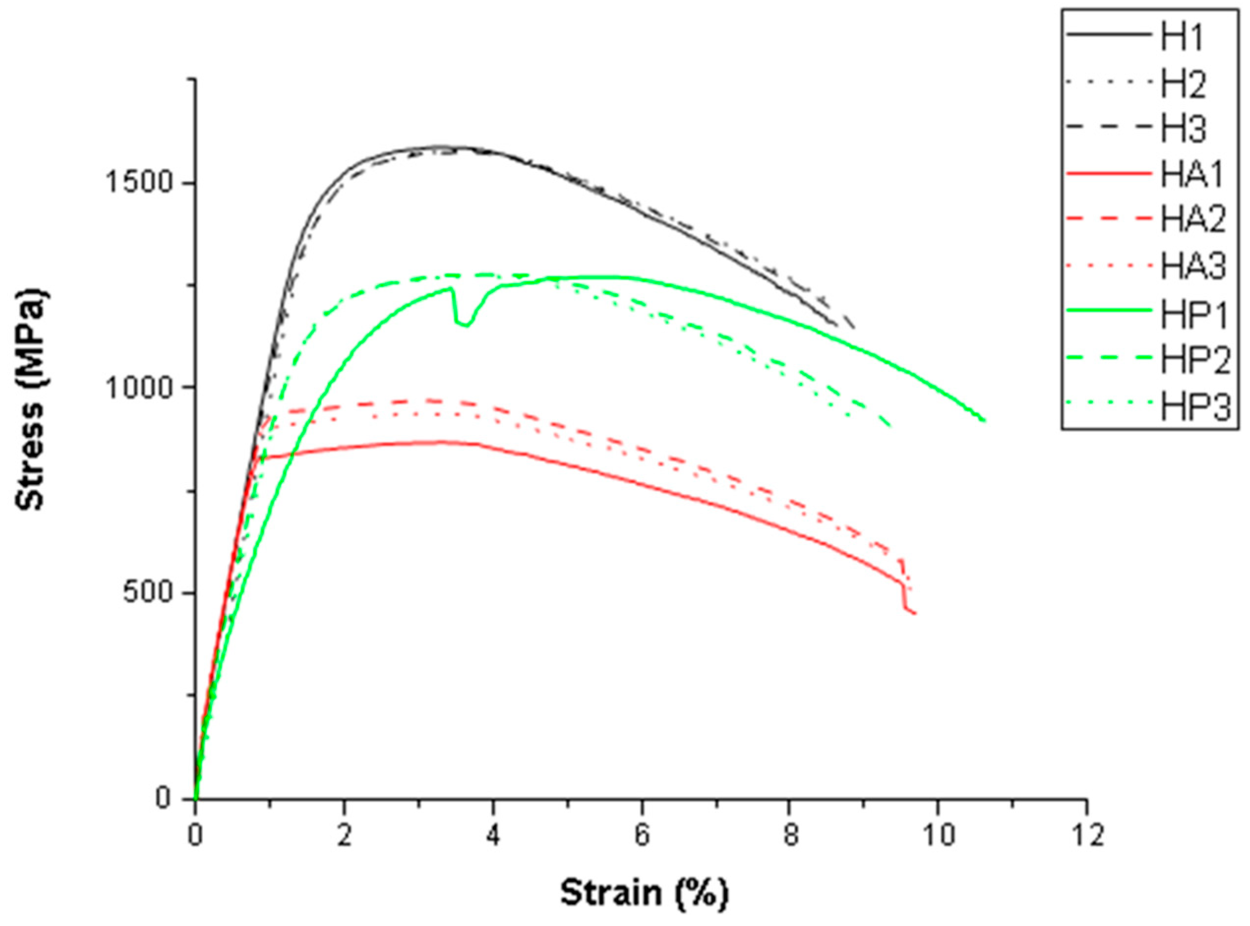
Figure 1 shows the stress–strain deformation curves of the investigated samples. After the tensile test, all the samples showed ductile behavior.
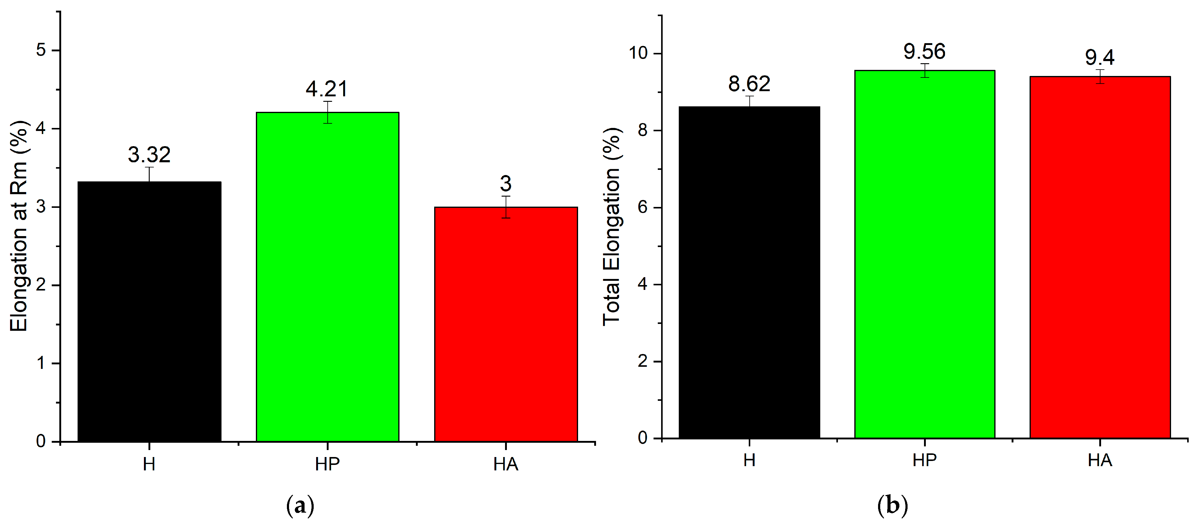
The tensile test results for Hardox 450 steel in three different surface conditions—uncoated, polyurea-coated, and alumina-coated—reveal the influence of surface treatments on the mechanical properties of the base material. The comparison focuses on tensile strength (TS), yield strength (Rp0.2), and elongation (%), which provide insights into the material’s load-bearing capacity and deformation characteristics (
Figure 2 and
Figure 3).
The uncoated Hardox 450 steel exhibits high tensile and yield strength (1579 MPa and 1474 MPa, respectively) and moderate ductility. The narrow margin between the yield and tensile strengths suggests limited strain hardening, a characteristic typical of wear-resistant steels. The elongation value of 8.62% indicates a reasonable capacity for plastic deformation before fracture, which supports energy absorption in high-impact environments.
Polyurea-coated Hardox 450 steel results in a slight decrease in yield and ultimate tensile strength (1218 MPa and 1184 MPa, respectively), with reductions of approximately 22% in tensile strength and 19% in yield strength compared to the base material. The results revealed that the polyurea coating adheres well to the substrate and contributes to the overall structural integrity under tensile loading. Despite this decline, the polyurea coating adheres well to the substrate and supports overall structural integrity under tensile loading. The coating preserves sufficient ductility while adding protective characteristics, making it a suitable option for applications that demand a balance of toughness, flexibility, and surface durability.
In contrast, applying an alumina coating results in a notable reduction in both tensile strength (by ~41%, 925.55 MPa) and yield strength (by ~39%, 897.81 MPa) relative to the uncoated base material. These values suggest that the alumina layer may act as a brittle barrier, inducing surface-level microcracks that weaken the substrate’s load-bearing capacity. The ductility retention indicates that the base material still accommodates plastic deformation, but the coating inhibits the development of strength during loading.
These results highlight the effects of using different coatings on Hardox 450 steel. Polyurea is the preferred coating for applications requiring a balance of strength retention, ductility, and protective surface characteristics. Alumina coatings, though functional for specific surface functions, may compromise structural performance and should be applied with caution where mechanical strength is critical.
From
Figure 4, which shows the macroscopic appearance of the experimental samples (one example of each type investigated) after the tensile test, distinct fracture behaviors can be observed. In the case of the polyurea-coated samples, the fracture zone is displaced toward the end of the coating, indicating that the coating may influence the stress distribution during deformation. Conversely, in the alumina-coated samples, the ceramic layer detached from the fracture zone, suggesting poor adhesion or brittle failure of the coating under tensile loading.
3.2. Vickers Hardness Test
Figure 5 shows the optical microscopy images for each type of investigated sample, along with the test pattern for the hardness measurement and the SEM images from one of the hardness testing points. The determinations were carried out on the same type of samples used in the tensile tests, only on Hardox 450 steel, to gain a better understanding of the tensile behavior and the fracture mechanisms involved.
In
Figure 6, the Vickers microhardness profile on the investigated samples is presented.
The average Vickers microhardness showed a reduction in the hardness of the Hardox 450 steel substrate for the coated samples compared to the uncoated reference. The uncoated (H) samples had an average hardness of 507.88 HV, while the polyurea-coated samples exhibited a slightly lower average hardness of 458.19 HV for the Hardox 450 steel substrate. The most significant decrease was observed in the alumina-coated (HA) samples, with an average substrate hardness of 319.74 HV. These results indicate that although the deposition conditions of both coatings affected the substrate hardness, the polyurea layer had a relatively minimal impact. In contrast, the higher temperatures involved in the alumina deposition process likely caused microstructural changes in the substrate, leading to a more pronounced reduction in hardness.
The hardness profiles revealed that in the HP samples (Hardox 450 steel coated with polyurea), the microhardness increased gradually from the coated surface toward the center of the sample. An average value of 422.74 HV was recorded near the coated surface, compared to 491.31 HV in the region farther from this. This supports the conclusion that the low temperature involved in the polyurea coating process does not significantly affect the internal structure of the metallic substrate. However, this behavior was not observed in the alumina-coated samples, which suggests, once again, that temperature influences the microstructural aspects and has an impact on substrate hardness.
The experimental results demonstrate a strong correlation between the microhardness of the Hardox 450 steel substrate and its tensile performance. The uncoated steel exhibited the highest hardness and mechanical strength, reflecting the material’s original properties. For the coated Hardox 450 samples, it was observed that the coating method and the application temperature play a critical role in determining the material’s mechanical behavior.
3.3. Macroscopic and Microscopic Analysis of Samples After Tensile Testing
3.3.1. Stereomicroscopic Analysis of Samples After Tensile Testing
Macrofractographic analysis of the samples after tensile testing (one representative sample from each group studied) in different structural conditions is presented in
Figure 7,
Figure 8 and
Figure 9.
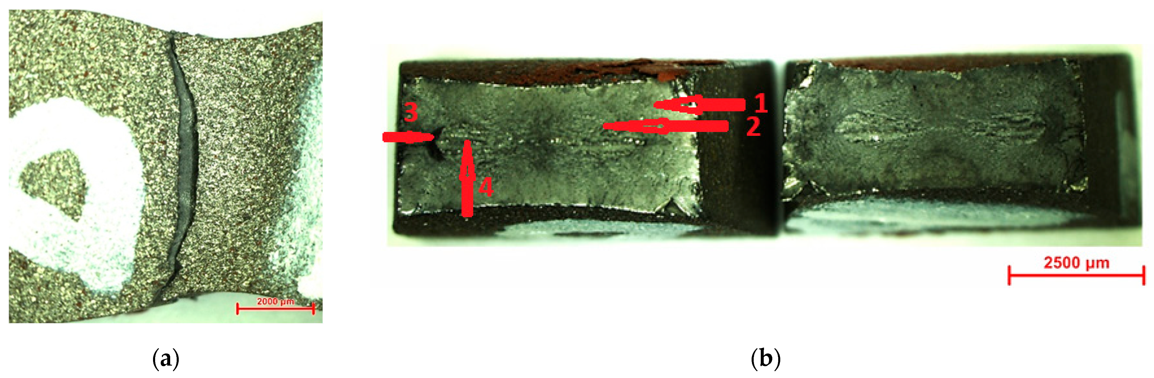
The fracture surface morphologies vary significantly depending on the coating method, as illustrated by the cross-section images of the failed specimens. In the case of the Hardox 450 steel samples (H1, H2, H3), characteristic areas were observed after tensile tests. Specifically, two distinct areas were identified: the edge shear zone (1) and the static zone of final fracture (2). These zones are separated by the edge line with a rectangular perimeter (3).
The macrofractographic features of sample H1 are presented in
Figure 7.
In the longitudinal plane image (
Figure 7a), a slight elongation before fracture is evident, indicating a ductile fracture mechanism. The fracture propagated in a zig-zag pattern, which is characteristic of ductile failure. In the cross-section views, two distinct zones were identified: the edge shear zone (1) and the final static fracture zone (2). The relatively large extent of the edge shear zone suggests a predominantly ductile fracture process, with a prolonged phase before the onset of sudden final failure. These two zones are clearly delineated by the rectangular edge perimeter line (3).
The images highlight the two distinct fracture zones of the sample, with the final static fracture zone exhibiting a mixed morphology that combines features of both cleavage and ductile failure. The macrofractographic features observed in samples H2 and H3 were consistent with those of sample H1, displaying similar fracture morphology and zone distribution.
The macrofractographic features of the HA1 sample coated with alumina are shown in
Figure 8. A similar morphology of the sudden final static fracture was observed, centrally confined by the mark line, with fracture propagation perpendicular to the direction of the applied tensile load. This mark line outlines distinct slip zones characterized by parallel fracture planes. A zig-zag fracture front, along with slight elongation prior to failure, was also observed, indicating a mixed fracture mode that combines both ductile and brittle characteristics.
Notably, zone 1 (the edge shear zone) differs significantly from that observed in the uncoated samples, being more extended, suggesting a modified fracture behavior due to the ceramic coating. These observations were consistently confirmed in samples HA2 and HA3 as well.
The macrofractographic images of the HP1 tensile specimen coated with polyurea are presented in
Figure 9. These images show significant differences compared to those of the samples coated with alumina. The variation in fracture morphology can be attributed to the coating conditions; the polyurea coating was applied at much lower temperatures, which have a minimal impact on the internal structure of the metallic substrate.
The macrofractographic images of samples HP1, HP2, and HP3 reveal several key features indicative of ductile fracture behavior. A slight elongation of the specimens occurred before fracture, confirming a predominantly ductile failure mechanism. The fracture front propagated perpendicular to the direction of the applied tensile load.
All three characteristic regions typically observed in tensile specimens with a rectangular cross-section were clearly defined, resembling the features found in the corresponding uncoated Hardox 450 steel samples. The marginal shear rupture zone is notably extensive, wider than in the uncoated specimens. In contrast, the central static final rupture zone is narrower compared to that of the uncoated samples. The delimiting mark line (3), with its rectangular perimeter, remains well defined. Additionally, small, localized cracks (4) were identified in the central area, oriented perpendicular to the direction of loading.
3.3.2. Computed Tomography Analyses of Samples After Tensile Testing
The CT images in
Figure 10 support the observations made through stereo macrostructural analysis of the samples after the tensile test, highlighting the presence of three distinct zones: the shear edge zone, the final static rupture zone, and the edge line. Furthermore, in the case of the polyurea-coated samples, cracks were observed in the final static rupture zone, indicating localized damage associated with the fracture process in this region.
3.3.3. Scanning Electron Microscopy Analyses of Samples After Tensile Testing
To complement the stereo macrostructural observations, SEM microscopy was employed.
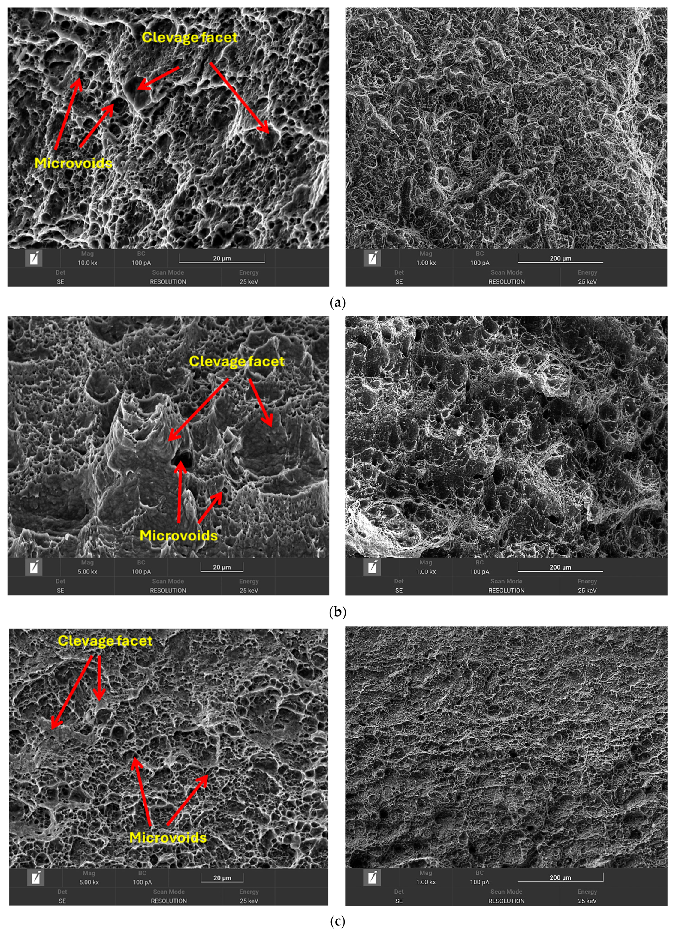
Figure 11 presents SEM images of the tensile fracture surfaces for the standard Hardox 450 steel, alumina-coated Hardox 450 steel, and polyurea-coated Hardox 450 steel samples, respectively.
Both the uncoated Hardox 450 steel and the polyurea-coated samples exhibited typical ductile fracture characteristics. As illustrated in
Figure 11a,c, the fracture surfaces display uniform and smooth features, indicating a relatively homogeneous microstructure, along with the presence of dimples and tear ridges, hallmarks of ductile failure.
In contrast, the SEM images of the alumina-coated Hardox 450 steel samples reveal multiple cleavage facets, which are characteristic of a brittle fracture. This suggests a mixed fracture mode that combines both ductile and brittle features. The presence of cleavage planes indicates a low-energy, rapid fracture mechanism with minimal plastic deformation.
3.4. Numerical Simulation Performed with 5.56 × 45 mm Ammunition
Figure 12 illustrates the structure of the 5.56 × 45 mm bullet used in the simulation, along with its impact interaction with the Hardox 450 target model. The lead core of the 5.56 × 45 mm projectile was imported from the Autodyn material library as pure lead. The material model for the ceramic layer was also adopted from the Autodyn library. Additionally, the LINE-X polyurea coating was modeled as a hyperelastic rubber, with both its material and strength models sourced from the same library (
Figure 13).
The numerical simulation demonstrated a significant improvement in ballistic performance for the ceramic-coated Hardox 450 sample when impacted by a 5.56 × 45 mm projectile traveling at 900 m/s. In the case of the uncoated Hardox 450 steel, the projectile fully penetrated the target, with the residual velocity of the bullet core measured at approximately 420 m/s. After the addition of alumina layers, the bullet stops in the structure, even if the structure is partially penetrated. Conversely, the addition of a thick polyurea layer resulted in only a marginal improvement in ballistic performance. The front-facing polyurea coating reduced the projectile velocity by less than 5%. At the same time, the backing material does not affect ballistic resistance.
In
Figure 14, the bullet component velocities are plotted against time, while
Figure 15 shows a comparative material displacement during impact in the tested samples.
The experimental ballistic testing of the Hardox 450 steel plates (H samples) confirmed the general trends observed in the numerical simulations. The remaining velocity of the bullet after impact with the uncoated Hardox 450 sample was estimated from high-speed video footage to be 305 m/s, which is reasonably comparable with the 420 m/s predicted in the simulation, considering simplifications in the model and experimental variability (
Figure 16).
However, the ballistic impact experiments on the HP and HA samples revealed results that were contrary to the simulation predictions. The Hardox 450 model implemented in simulation was validated by experimental shooting, revealing that both simulation and experiment had similar results regarding the speed of the bullet after impact. An effect that cannot be numerically simulated is the degradation of the Hardox 450 material strength during alumina layer deposition, inflicted by thermal conditions. In numerical simulation, the alumina layer should prevent the projectile to penetrate. When subjected to impact by a 5.56 × 45 mm projectile at 900 m/s, the HA (alumina-coated Hardox 450 steel) sample was easily penetrated, and the measured residual velocity of the steel core was 493 m/s, significantly higher than the 305 m/s recorded for the uncoated Hardox 450 steel sample. Furthermore, the penetration bore in the alumina-coated Hardox 450 steel sample was visibly larger than that in the Hardox 450 steel sample.
Balistic impact analysis further showed that in the Hardox 450 steel sample (H), only the steel core and lead slug protruded through the sample, while the copper jacket was radially dispersed, remaining outside the main penetration channel (
Figure 17a). In contrast, in the HA sample, the larger bore diameter allowed a significant portion of the copper jacket to pass through the target (
Figure 17b). This resulted in an increased behind-armor threat, as the fragment funnel patterned dispersion of those fragments can wound individuals that are not in the actual trajectory of the main parts of the bullet.
In the case of the HP sample, the target successfully stopped the bullet and prevented any dispersion of fragments (
Figure 17c). The projectile stopped within the Hardox 450 steel, with no visible deformation observed on the backface. Upon impact, the polyurea layer formed a temporary radial cavity around the point of contact, effectively trapping bullet fragments within the structure. The cavity collapsed to its original shape within 500 µs after impact. Using the rubber material model in order to simulate the dynamic impact between the bullet and HP structure was infirmated by experiments, because in the simulations the addition of the polymer layers had marginal effect on the stopping potential of the HP structure, while the experiments proved the contrary. This difference can be attributed to the much higher tenacity of the Line X, compared with standard rubber, used as material model in simulations. The results obtained from the experimental samples after the ballistic test using 5.56 × 45 mm ammunition are shown in
Table 2.
4. Conclusions
The study demonstrated a clear link between coating type, mechanical strength, and fracture behavior of the investigated samples. The uncoated Hardox 450 steel showed the highest tensile strength (1579 MPa) and hardness (507.88 HV), with ductile fracture features confirmed by stereomicroscopy, CT, and SEM analysis. Polyurea-coated Hardox 450 samples retained good mechanical performance with minor reductions in strength and hardness, indicating that the low-temperature coating process preserved the steel’s microstructure. Fracture analysis showed continued ductile behavior and good coating adhesion. In contrast, the alumina-coated Hardox 450 samples exhibited significant reductions in tensile strength and hardness due to the high-temperature deposition process, which likely altered the substrate’s microstructure. Fracture surfaces revealed brittle features and poor adhesion, indicating a shift toward mixed-mode failure.
The numerical model developed to simulate the ballistic impact between 5.56 × 45 mm projectiles and the experimental samples proved to be a valuable tool for predicting the ballistic resistance of uncoated Hardox 450 steel. However, it demonstrated limited accuracy in predicting the response of HP and HA samples (polyurea- and alumina-coated Hardox 450 steel samples).
The thermal effects associated with the alumina deposition process on the Hardox 450 steel harmed the ballistic performance of the samples. This was evident from the experimental tests, where the alumina-coated Hardox 450 samples exhibited lower ballistic resistance than the reference uncoated Hardox 450 steel. In contrast, the polyurea-coated Hardox 450 samples provided adequate ballistic protection against steel core bullets, even at high impact velocities. Also, the results highlight the potential of polyureas to retain all fragments resulting from impact, providing additional protection against secondary impact threats.
The HP structure can successfully provide ballistic protection against threats commonly encountered in conflict zones (7.62 × 39 mm FMJ and 5.56 × 45 mm NATO armor-piercing rounds). This suggests that polyurea layers could be directly applied to both sides of a light armored vehicle, thereby significantly enhancing its ballistic protection ability.
In conclusion, LINE X polyurea coatings proved to be the more suitable coating for applications requiring a balance of mechanical strength, ductility, and impact protection, whereas the alumina coating process adversely modify the microstructure of the HARDOX 450 steel substrate due to the highest deposition temperature, fact that affect the mechanical properties and ballistic performance samples.


 ,
, 


