1. Introduction
Supercapacitors (SCs) typically comprise four key elements, the positive electrode, negative electrode, electrolyte, and separator, each playing a crucial role in the energy storage process. The electrodes engage in surface reactions—such as adsorption/de-adsorption or redox reactions—to capture electrical charges, while the electrolyte supplies the necessary ions for these electrochemical interactions [
1,
2]. The separator is essential to prevent short circuits between the positive and negative electrodes. In most cases, solid-electrolyte-based SCs eliminate the need for separators as the electrolytes themselves function as separators, whereas liquid-electrolyte-based systems do require separators [
3]. The piezoelectrochemical mechanism indicates that mechanical strain applied to the piezoelectric film generates a voltage, which drives ions toward the interface between the electrodes, thus forming an electric double layer or pseudocapacitance at that interface, enabling the storage of electrochemical energy. This integration of two distinct energy processes—mechanical energy harvesting from the piezoelectric potential and electrochemical energy storage from ion movement—enables a continuous power supply generated by the body’s mechanical movements, eliminating the need for external power [
4].
In light of ecological and environmental challenges associated with energy harvesting, piezoelectric nanogenerators (PNGs) emerge as a promising, sustainable, and plentiful source of energy for the future [
5]. However, the electricity generated by PNGs is dependent on the mechanical energy provided, which tends to be intermittent, making it unsuitable for electronics that require a continuous power supply. To address this limitation, a self-charging flexible supercapacitor (SCFS) has been developed, capable of harvesting irregular mechanical energy, converting it into electrical power, and storing it simultaneously. These synergistically integrated microelements (harvesting and storage) are expected to work more efficiently, with less electrical losses if they are incorporated together in a common structure, sharing the same substrate, and even some functional parts (e.g., electrodes) [
6,
7].
Recently, copper-cobalt-nickel oxide (CuCoNiO
4) has been incorporated into a poly(vinylidene fluoride) (PVDF) matrix at varying weight percentages to achieve high performance. This structure has been used as a separator while utilizing CuCoNiO
4 nanowires on carbon cloth (CC) as the positive and negative electrodes. The self-charging capabilities of this device are confirmed under bending stress. The PSCFS showcases a remarkable increase in open-circuit potential from approximately 35 mV to about 845 mV when subjected to bending at 180° with a frequency of 1 Hz. This device has the potential to power various portable electronics [
8]. Jadhav et al. reported an MXene-incorporated polymeric piezo separator of a polyvinylidene fluoride (PVDF) matrix and MXene (Ti
3C
2Tx) sheets as electrodes [
9]. This integration induces a degree of dipole moment alignment and improves the charge transfer process to the supercapacitor part. A capacitance of 61 mF·cm
−2, energy density of 24.9 mJ·cm
−2, and power density of 1.3 mW·cm
−3 have been reported in this case. A solid-state self-charging supercapacitor power cell utilizing a NiCoP/NiCoN heterostructure as the positive electrode, prepared via in situ phosphonitridation, and active carbon for energy storage has demonstrated remarkable performance, achieving a capacitance of 3544 mF·cm
−2 and a high energy density of 62.1 W·h·kg
−1 at 850 W·kg
−1 [
10]. This system benefits from an integrated P(VDF-TrFE)/BTO (barium titanate) piezo-film separator, providing a self-charging voltage of 132 mV within 155 s, highlighting its potential for self-powered wearable electronics. The electrochemical performance of the MnO
2 self-charging supercapacitor power cell has revealed a device capacitance of 0.45 F·g
−1, an energy density of 91 mW·h·kg
−1, and a power density of 9.9 kW·kg
−1, operating over 1.2 V. It has been noted that the MnO
2 SCSPC based on Al foil achieved a self-charge potential of 110 mV in 300 s when stimulated by human touch, whereas a variant on conductive fabric recorded only 45 mV in the same timeframe, illustrating the impact of the current collector [
11]. Another approach by Song et al. demonstrated a self-charging SCSPC using functionalized carbon cloth, achieving a capacitance of 357.6 F·m
−2 and self-charging to 100 mV in 40 s [
12]. Additionally, a CNT-based SCSPC has showcased a remarkable areal capacitance of 1.2 mF·cm
−2, with the ability to self-charge up to 70 mV in 40 s under a force of 70 N [
13]. An energy harvesting system that combines single-walled carbon nanotube (SWCNT) film electrodes with a metalized P(VDF-TrFE) film has been proposed [
14]. The unique asymmetric output characteristics of the piezoelectric P(VDF-TrFE) film enable effective charging of the supercapacitors when subjected to mechanical impacts. The flexible and transparent supercapacitors demonstrate a remarkable specific capacitance of 50 F g
−1, achieving an open-circuit voltage of 500 mV within just 20 s of force application. Furthermore, the hybrid piezo-supercapacitor system can generate a maximum voltage of approximately 650 mV. This work highlights a straightforward approach to developing self-powered piezo-supercapacitor systems, which may pave the way for innovative applications in wearable electronics. Siloxene-based self-charging supercapacitor power cells that utilize siloxene sheets as supercapacitor electrodes and electrospun siloxene-incorporated PVDF piezofibers as separators coated with ionogels have also been reported [
15]. Temperature limitations have been recently overcome with β-cyclodextrin/polyvinylpyrrolidone/Ni@MnCO
3 on cotton fabric with polyvinylidene fluoride and polydimethylsiloxane used to build the smart textile supercapacitor, which produced 19.6 V at −80 °C and exhibited a gravimetric capacitance of 94.7 F·g
−1 with excellent cyclic stability beyond 50,000 [
16]. Thus, the system can address the need for wearable electronics that are implanted in space suits or winter clothing exposed to harsh climates.
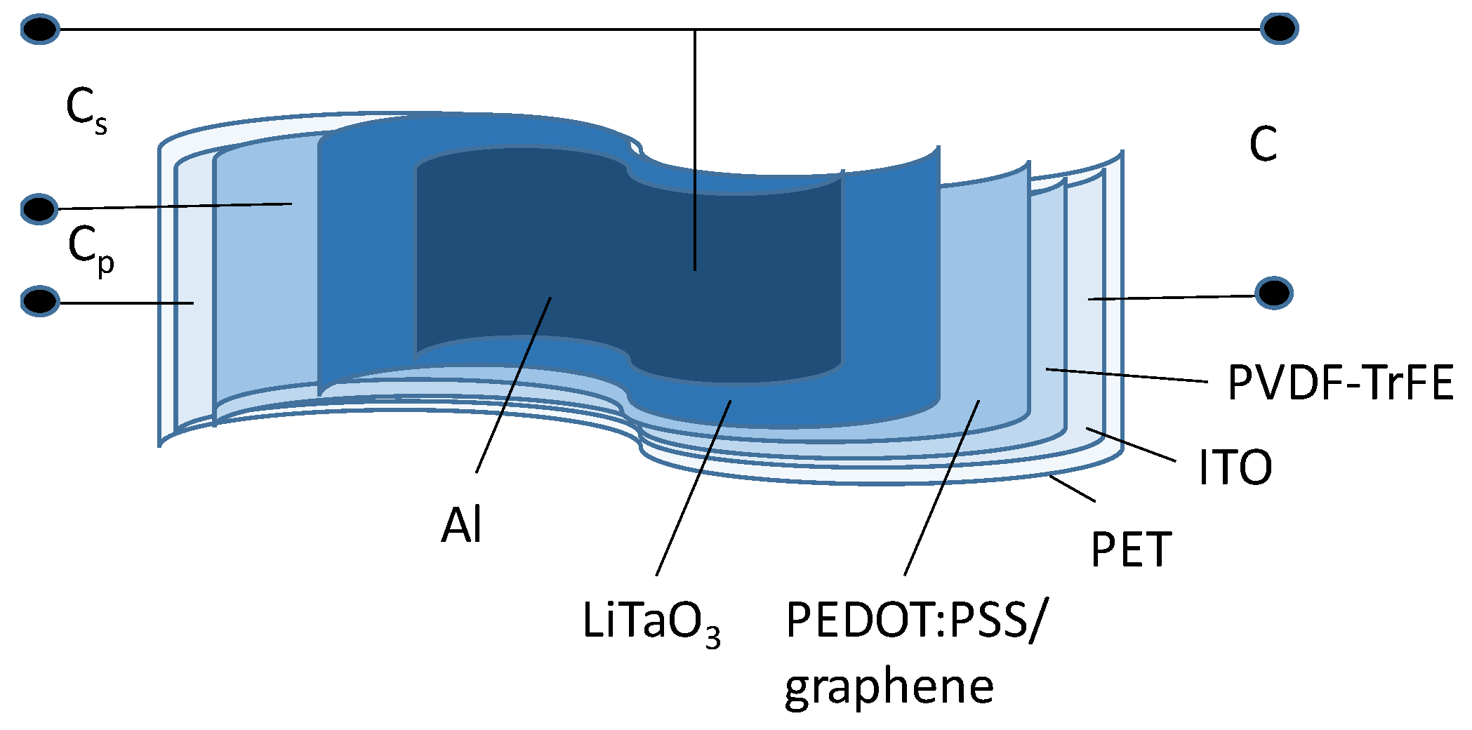
As seen, supercapacitors offer a promising energy storage solution that bridges the gap between traditional capacitors and batteries. However, their performance still needs improvement, avoiding a trade-off between the functions of the harvesting and storage part of the component. In addition, conventional processes should be used for the fabrication to make the synergistic device standard and cost-effective. Additionally, a variety of designs and parameter ranges have been achieved, without systematically targeted applications. Increasing the energy storage capacity while maintaining the fast charging and discharging capabilities is a critical challenge. Despite advancements in self-charging supercapacitors, a specific gap exists in the development of thin-film devices that effectively integrate piezoelectric materials for enhanced energy storage. Many existing devices rely on thicker film configurations or complex materials, hindering their potential for flexible and wearable applications. Furthermore, the long-term durability and stability of piezoelectric-enhanced supercapacitors, particularly under mechanical stress, remains a significant concern. This work addresses this gap by introducing a novel, flexible, thin-film supercapacitor architecture that combines a piezoelectric PVDF-TrFE film with LiTaO3 as a charge-generating and charge-transferring layer. The unique contribution lies in the synergistic integration of these materials within a thin-film structure, aiming to enhance both energy storage capacity and long-term stability. To the best of the authors’ knowledge, there are no reported studies involving LiTaO3 as a solid-state electrolyte and integrated with a piezoelectric harvester component in a single self-charged element with potential application as a biomedical sensor power supply. The device comprises a flexible poly (ethylene terephthalate) (PET) substrate, an indium-tin oxide (ITO) electrode, a poly(vinylidenefluoride-trifluoroethylene) (PVDF-TrFE) piezoelectric film (also separator), a poly (3,4-ethylenedioxythiophene) polystyrene sulfonate (PEDOT:PSS)/graphene as an intermediate electrode and reinforcing layer, a LiTaO3 layer (positive ion source), and an aluminum rear electrode. The piezoelectric layer is expected to contribute to charge generation under mechanical stress or vibration, thus potentially boosting energy storage capacity. The degradation over time, especially under mechanical stress or varying environmental conditions, will be overcome due to the great durability and thermal stability of the lithium tantalate. For enhanced performance, lithium tantalate is used in conjunction with the conductive polymer in a composite like PEDOT:PSS: graphene, to improve its ionic conductivity and overall efficiency as an electrolyte, speeding up the charging/discharging process.
When considering the integration of lithium tantalate (LiTaO
3) in devices with application in the medical field, it is important to define the specific parameters required for powering these devices, including voltage, current, and power requirements, as well as the associated thermal stability that LiTaO
3 can provide. Wearable health monitors have the following power supply requirements. Voltage range: These devices typically operate at 1.5 to 3.3 V. Current: They can start from microamps (µA) for low-power sensors in monitoring devices. Power: On the order of milliwatts (mW). Energy density: For wearable sensors, the typical energy densities are in the range of 20 to 100 Wh/kg to support continuous monitoring for long durations without frequent recharging. Implantable sensors often have lower energy density requirements, generally between 10 and 50 Wh/kg, since they may operate intermittently and prioritize size and biocompatibility. Power density: The wearable sensors require power densities ranging from 0.1 to 10 kW/kg depending on the type of monitoring, with higher power demands during active data transmission or stimulation (e.g., muscle contraction). At the implantable sensors, the power densities can be more modest, typically around 0.1 to 1 kW/kg due to lower energy demands and the need for longevity. Capacitance: The wearable sensors generally require capacitance values in the range of a few to few hundreds of farads per gram (F/g) to ensure rapid charge/discharge cycles for real-time data processing [
17,
18,
19,
20].
The aim of this study is to electrically characterize the performance of a novel, flexible, thin-film supercapacitor that integrates a piezoelectric PVDF-TrFE film and LiTaO3 to enhance energy storage and self-charging capabilities. It is focused on the supercapacitor component, as the piezoelectric partition is standard, a PVDF-based transducer. Frequency-dependent capacitance behavior and charge–discharge characteristics are explored to evaluate its potential for wearable sensing electronics.
2. Materials and Methods
PET samples were cleaned with isopropyl alcohol in a supersonic bath. PET substrates were covered by indium-tin oxide (ITO), as it possesses sufficient electrical conductivity and good mechanical durability during multiple bending cycles. The ITO provides a suitable surface for subsequent layer deposition, enabling better adhesion and electronic coupling with materials like PVDF-TrFE, which has a dual function—to generate charges in response to mechanical loading and to prevent the electrodes of the system from short-circuiting. ITO film was produced by the vacuum RF sputtering of an In:Sn = 95:5w% 3-inch target in an oxygen atmosphere at the following conditions: oxygen partial pressure of 2 × 10
−4 Torr, total (argon + oxygen) sputtering pressure in the chamber of 2.5 × 10
−2 Torr, sputtering voltage of 1.25 kV, plasma current of 180 mA, and sputtering power density of 31.8 W/inch. The produced ITO film had a thickness of 360 nm, measured by a Tencor profilometer, and a sheet resistance of 22.9 Ω/sq, measured by a Veeco FPP 5000 four-point probe setup. PVDF-TrFE ink was screen-printed and annealed at 120 °C for 15 min to remove the solvent. A water solution of PEDOT:PSS/graphene was spray-coated over the PVDF-TrFE at a temperature of 110 °C, an aerosol pressure of 3.5 bar, and a nozzle-to-substrate distance of 5 cm. The PEDOT:PSS/graphene facilitates better ion transport, reduces resistance, and enhances overall device performance. It also serves as a common electrode for independent testing of both the storage and harvester part of the element, but can also be a connection of the capacitor, consisting of two sub-capacitive constituents due to piezo- and supercapacitance. The deposition conditions for PVDF-based solutions were initially optimized only for the piezoelectric energy harvesting element, integrated with PEDOT:PSS-based solutions [
21]. LiTaO
3 film with a thickness of 400 nm was deposited by high-power RF sputtering with a Li-enriched target composed of Li
2O
2/Ta
2O
5 (55:45 at.%) at an oxygen partial pressure of 1 × 10
−4 Torr, total (argon + oxygen) sputtering pressure in the chamber of 2.5 × 10
−2 Torr, sputtering voltage of 2 kV, plasma current of 210 mA, and sputtering power density of 60 W/inch. Finally, aluminum was thermally evaporated as a counter-electrode at a base pressure of 1 × 10
−6 Torr. The deposition procedure follows conditions described elsewhere [
22]. The area of the element was 1 cm
2. The impedance analysis of the devices was conducted by the Hioki IM3590 impedance analyzer (HIOKI E.E. CORPORATION, Nagano, Japan) in the range of 1 Hz–100 kHz. The charge–discharge reference cycling conditions were set by a functional generator and monitored by a Tektronix TDS 1012B (Tektronix, Inc., Beaverton, OR, USA) digital storage oscilloscope. The equivalent serial resistance, the storage capacity, and the charging current were recorded by a precise battery simulator and tester, Keithley 2281S-20-6 (Keithley Instruments, Solon, OH, USA), with an implemented DC supply of reference voltage. For mechanical stimulation of the piezoelectric part and durability testing of the entire element, a beam-shaped tester with regulated mass loading and frequency was used. The sample clamps were specifically designed to attach rectangular samples, holding them at one end while applying a twisting moment at the other end, thus inducing torsional stress within the sample. An observation of the sample surface was conducted by a scanning electron microscope SEM LYRA/TESCAN (TESCAN, Brno, Czech Republic). Atomic force microscopy (AFM) topography images were acquired using a Dimension 3100S-1 (Veeco, Plainview, NY, USA) system operated in air tapping mode, with a BudgetSensors Tap300Al-G cantilever (Veeco, Plainview, NY, USA) (nominal tip radius: 10 nm). The AFM topography images were processed and visualized using Gwyddion software v. 2.68. Raman spectroscopy of the LiTaO
3 film was carried out with a Renishaw micro-Raman spectrophotometer. The piezoelectric coefficient was measured by a PolyK d33 meter (PolyK Technologies, State College, PA, USA).
Figure 1 shows the structure of the proposed element and the possible capacitances that are formed between the outer electrodes or between one of the outer electrodes and the intermediate one.
3. Results and Discussion
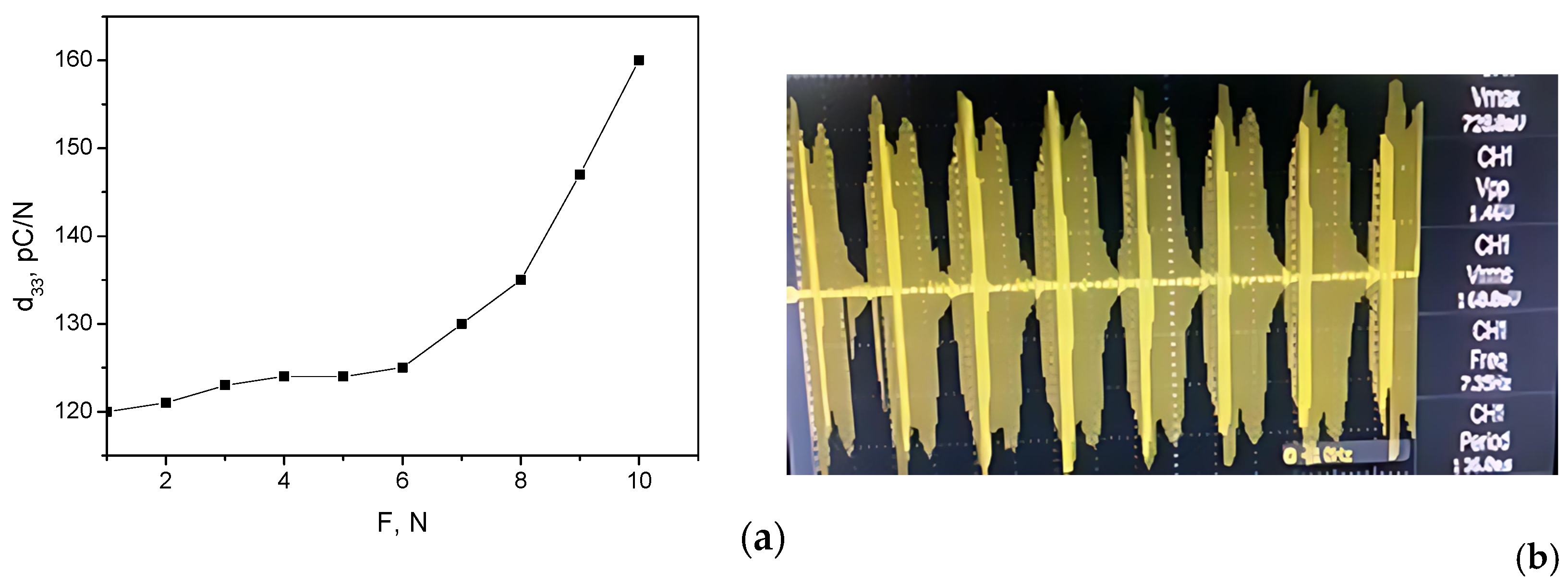
Figure 2a shows a measurement of the piezoelectric coefficient (d
33) as a function of the applied force, and
Figure 2b shows the maximum generated piezoelectric voltage without distortions of the signal’s shape. These measurements quantify the device’s ability to generate an electrical charge in response to an applied mechanical stress. d
33 accepts typical values for the PVDF-TrFE, which is an indication that the subsequent layers’ deposition has not damaged the piezoelectric properties of the polymer. The piezoelectric voltage measured at 10 N and vibrations of up to 10 Hz are characterized by an excellent periodicity. The non-ideality in the sinusoidal shape is due to the lack of electrode bonding and packaging of the structure, as well as due to working at high stress levels to determine the capability of the piezoelectric harvester to produce maximum voltage. In this case, it was 1.47 V from peak-to-peak and the maximum voltage reached 728 mV.
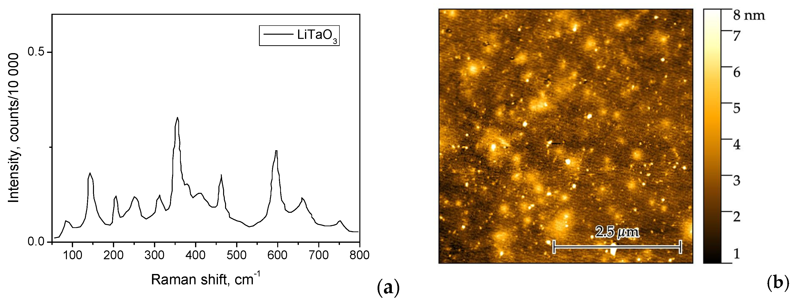
Figure 3a shows the Raman spectrum of the LiTaO
3 film. Characteristic peaks for LiTaO
3 were observed in the Raman spectra, which were ascribed to the rhombohedral phase existing in this material. Despite the weak signal due to the small thickness of the film, the Raman spectrum indicated that the sample contains a relatively high degree of crystallinity. The results are in good agreement with already published data [
23,
24].
Figure 3b shows the AFM of the LiTaO
3 film, which is characterized by a low RMS roughness of 1.92 nm. The smooth film is a precondition for uniform interfacial contact with the next layer and low losses due to contact resistance voltage drop.
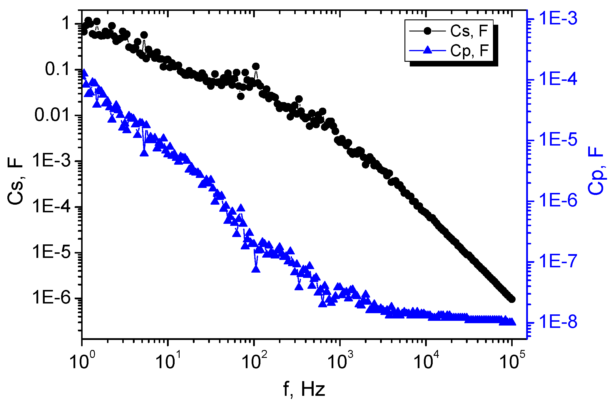
Figure 4 shows the frequency dependence of both the effective supercapacitor capacitance (C
s) and piezoelectric capacitance (C
p). In the low-frequency region of interest, the value of C
s at 1 Hz reaches 980 mF; at 10 Hz, it is about 170 mF; and at 100 Hz, it is about 50 mF. The plot reveals that C
s exhibits a significant decrease with increasing frequency, which is a typical behavior for an electrical double-layer capacitor (EDLC), which stores energy through electrostatic charge separation rather than electrochemical reactions. EDLC can charge and discharge very quickly because of this mechanism. The decrease in the capacitance by several orders of magnitude at frequencies greater than 1 kHz, however, is not considered a disadvantage, because of the low-frequency characteristic of the generation of piezoelectric voltage in wearable systems, activated mostly by human motion.
The possible mechanism behind this trend is rooted in the limitations of ion transport within the electrolyte at high frequency. At low frequencies, ions have sufficient time to accumulate at the electrode interfaces, resulting in larger capacitance values. However, as the frequency rises, the ions cannot quickly respond (diffuse and accumulate rapidly enough to follow the field) to the alternating current, thus resulting in a decrease in effective capacitance. The piezoelectric capacitance C
p, although smaller in magnitude, also shows a decrease with the frequency. This suggests contributions from interfacial capacitances within the device structure. At low frequencies, the piezoelectric film responds effectively to mechanical stress or vibration, generating a voltage and driving ion movement. As the frequency increases, the piezoelectric material may not be able to respond quickly enough to the alternating stress, resulting in reduced voltage generation and, consequently, lower observed capacitance, compared to the low-frequency region. C
p accepted the typical values for the PVDF-TrFE materials with the comparable thickness and size of the piezoelectric cell, which is an indication of the proper functionalization of the piezoelectric counterpart [
25].
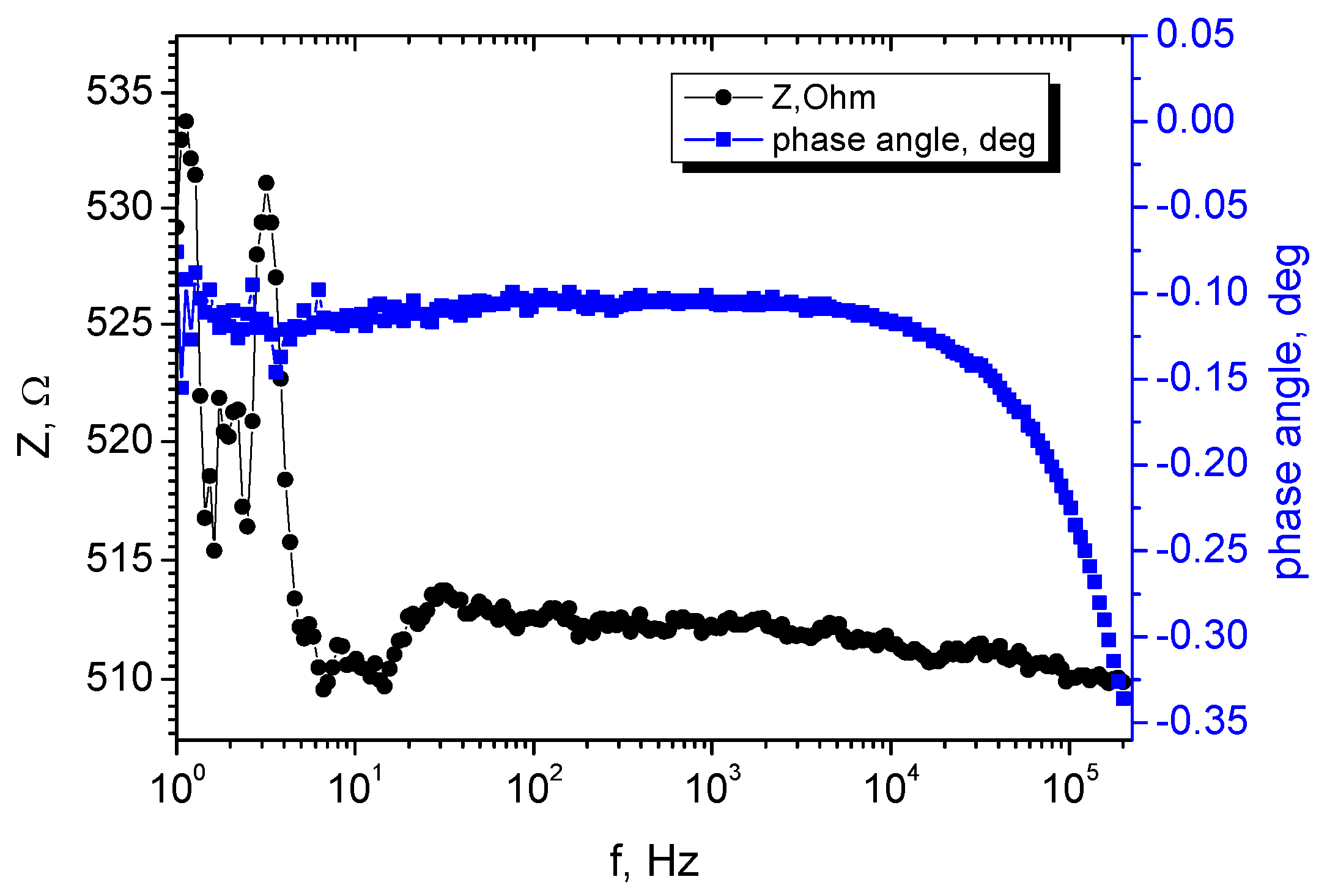
Figure 4 displays the impedance and phase angle as a function of the frequency for the proposed element. The relatively flat impedance profile, forming a plateau around 533 Ω in the low-frequency range, indicates the dominance of the inherent resistances of the different layers over the capacitive reactance. This is a relatively high equivalent series resistance (ESR) indicating that the supercapacitor can be used for power backup (typically >100 Ohms) [
26].
The phase angle plot (
Figure 5) also correlates with the impedance profile, initially being close to zero (resistive behavior) at low frequencies and becoming more negative (capacitive behavior) at higher frequencies. A possible explanation for this curve characteristic is that at the beginning of the generation process, the overall impedance is still relatively high due to the inherent resistance of the electrolyte, electrodes, interfaces, and the lack of ion motion. Since the resistive component dominates, the phase angle is close to zero, indicating that the voltage and current are nearly in phase. The phase angle does not reach −90 degrees with an increase in frequency, due to the limitations of ionic mobility. Ions cannot move instantaneously, so there is always a resistive component in the overall impedance. This resistive component limits the extent to which the phase angle can deviate from zero.
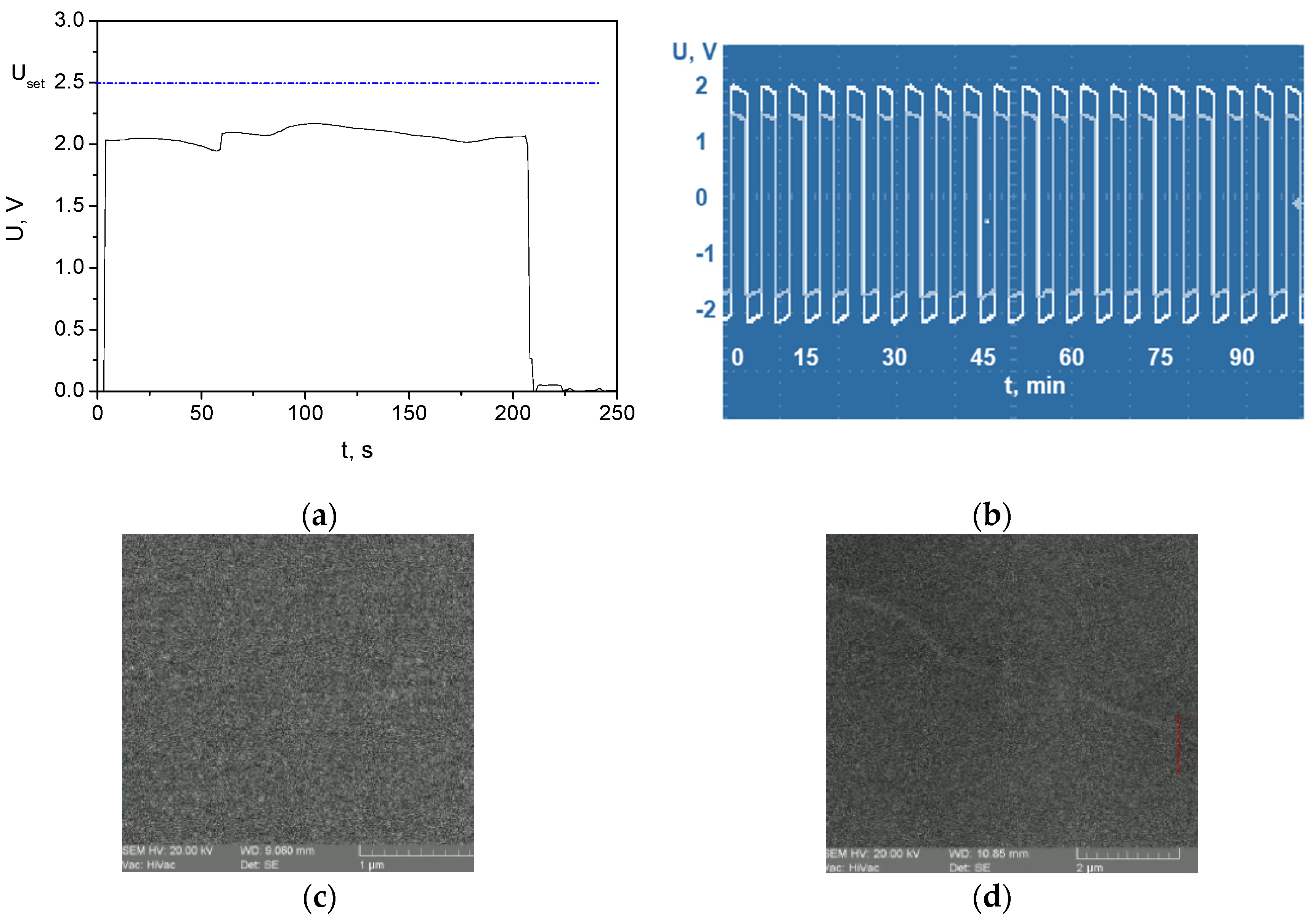
Figure 6a shows a typical charge–discharge cycle. The observed voltage plateau indicates the voltage profile of the supercapacitor during the charge–discharge cycles. The voltage of 2.5 V was set from the reference source with a value comparable to the voltage that is typically generated from the harvesting part of the element. The charging voltage was approximately 2 V ± 0.1 V. The retention voltage at cyclic charge/discharge conditions with a duration of 90 min is maintained stable with a value of 2 V ± 0.2 V (outer envelope of the pulses in
Figure 6b). After mechanical loading, causing multiple (beyond 1500) bending of the whole element, the retention voltage decreased to 1.4 V and remained stable for the same duration of multiple charge/discharge cycles with a deviation of ±0.2 V (inner envelope of the pulses in
Figure 6b). The degradation of the charge voltage of 600 mV after bending is relatively small, which is evidence of the great durability of the element, ascribed to the presence of graphene and LiTaO
3 in the structure. The slight deviation from the initial value of the voltage was attributed mainly to changes in the LiTaO
3 microstructure, due to its higher brittleness, compared to the other involved layers [
27].
Compared to the polymer layers (PVDF-TrFE, PEDOT:PSS), LiTaO
3 is a ceramic material and is inherently more brittle. This means it is more susceptible to crack formation under tensile stress, while the polymer layers are flexible and can absorb some of the stress. Therefore, the stress will be transferred to a more rigid layer (LiTaO
3). Interfaces between layers are also often stress concentration points. If the LiTaO
3 layer is not well bonded to the adjacent layers, shear stresses can develop at the interface during bending. These shear stresses can initiate cracks in the brittle LiTaO
3. The SEM images shown in
Figure 6c,d illustrate the differences in the lithium tantalite film before and after 1500 cycles of bending.
Figure 6c proves the uniform distribution of the particles in the as-sputtered LiTaO
3 film. However, as shown in
Figure 6d, after multiple bends, a crack is revealed across the entire monitored spot of the film. It can be concluded that the crack is shallow and therefore its effect on the voltage decrease of approximately 200 mV is considered negligible compared to the high number of bends.
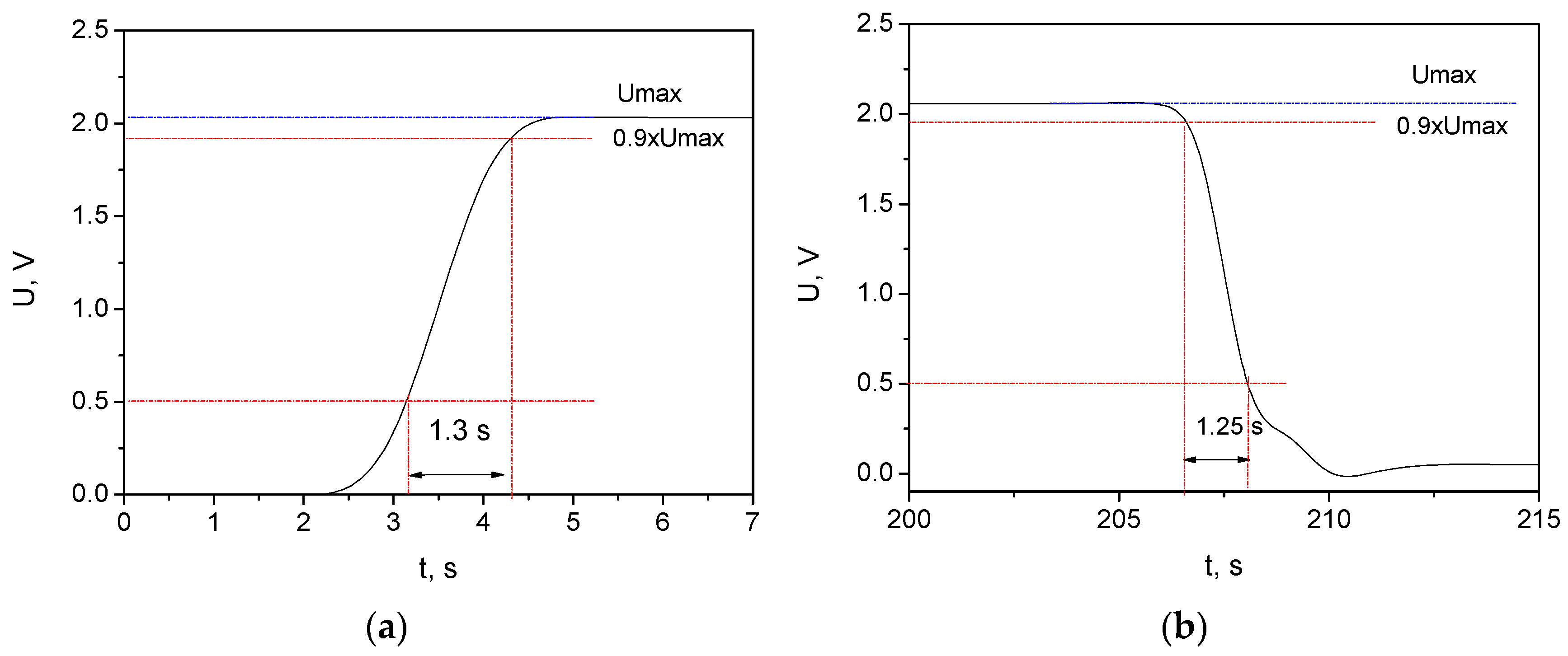
Figure 7 provides insights into the charge/discharge time analysis. More specifically,
Figure 7a shows the transient characteristic during charging of the developed supercapacitor, and
Figure 7b shows the transient characteristic during discharging of the supercapacitor. To determine the Coulombic efficiency (
CE) of the created microelectronic structure, the ratio of the “removed” charge from the supercapacitor to the “imported” charge used for storage in the supercapacitor is calculated, which is dependent on the charge and discharge current (which is equal in this case and accepts a value of 5 mA) [
28]. Then, the
CE can be determined by the following analytical expression:
where for constant current during charge and discharge,
Q =
I ×
t (
I and
t represent current and time, respectively).
In the case that
Idischarge =
Icharge, Formula (1) is simplified and accepts the form of
To determine the
CE of the specific microelectronic structure, a study was carried out from approximately 0.5 V to 0.9xVmax of the steady-state value. For voltages lower than 0.5 V during the discharge process of the supercapacitor, additional nonlinearity occurs in the transient characteristic. This nonlinearity of the transient response is due to some non-idealities in the transitions between the individual layers. Additionally, static charges arise in the process of research from scattered electromagnetic fields from the environment and due to the triboelectric effect [
29]. For the specific voltage range,
tdischarge = 1.25 s and
tcharge = 1.3 s, so
CE = 96.153%.
This value confirms that the higher the Coulombic efficiency, the less capacity the supercapacitor loses in each charge/discharge cycle, and the longer its potential lifespan is, as is also visible from
Figure 6b. Due to the lower ion mobility of the LiTaO
3 at room temperature [
30], the remaining lithium ions accumulated near the interface with the PEDOT:PSS/graphene layer and diffused, thus gradually being released in the course of the discharge process, resulting in a greater
CE [
31].
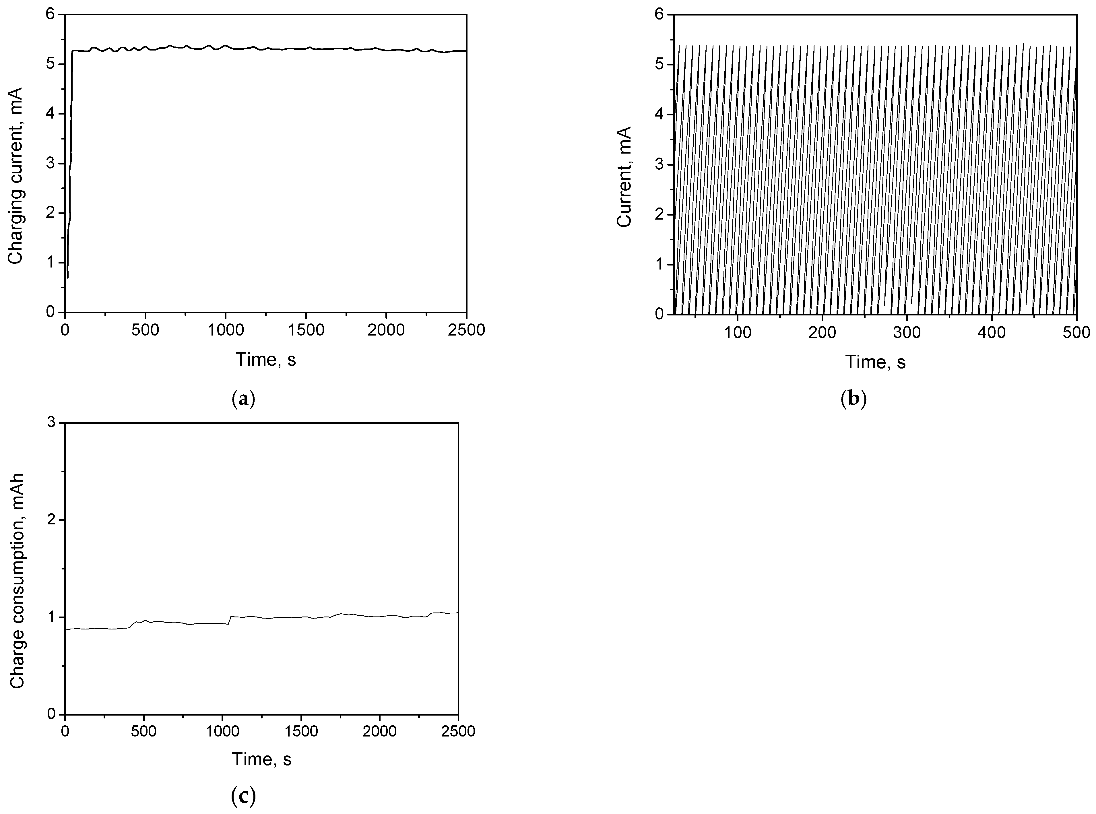
Figure 8a presents the charging current vs. time plot and shows a non-zero initial current value of 0.7 mA. The supercapacitor has a small amount of residual charge due to the presence of the piezoelectric component. It may appear because of the measurement attachment during the element testing, which probably leads to a slight bending of the segments. The rapid ramp to 5 mA in under a minute along with the plateau current profile with a minimal fluctuation between 5.2 and 5.3 mA demonstrates efficient energy storage and stable performance during the charging process.
Figure 8b shows the current through the supercapacitor being subjected to a repetitive charge and discharge cycles. It is characterized by a high degree of symmetry. In practical terms, this indicates that the supercapacitor can be charged and discharged efficiently and reliably, with minimal loss or variation, suggesting good symmetry between the two processes of charging and discharging. This symmetry is desirable because it reflects stable performance and consistent energy storage and release capabilities of the supercapacitor.
Figure 8c shows that the charge consumption varies from 0.87 mAh to 1.05 mAh for the period of 2500 s. The piezoelectric harvester is actively generating more charge than the load is consuming during this period. The increase in charge (0.18 mAh) represents the net energy harvested and stored in the supercapacitor during the specified time period. This implies that the mechanical input to the piezoelectric element was sufficient to overcome any leakage current and the load’s current demand. A possible explanation for this phenomenon is the high sensitivity of the piezoelectric partition.
Considering a voltage of 2 V, charging current of 5.3 mA, charging time of 1.76 s, and mass (m) of 0.46 mg (or 0.00000046 kg, obtained from an area of 1 cm
2 and from the thicknesses and densities of the PVDF, PEDOT:PSS/graphene, and LiTaO
3), the specific capacitance is obtained from Equations (3)–(5):
The following calculations are valid for the power density (Equations (6)–(8)): For the energy density calculation, the following are achieved (Equations (9)–(11)): To highlight the advantages of the proposed PET/ITO/PVDF-Tr-FE/PEDOT:PSS:Graphene/LiTaO
3/Al supercapacitor structure,
Table 1 presents a comparative analysis of its energy density, power density, and other key features alongside those of similar devices from the literature, also including information on deposition methods, compactness, flexibility, and mechanical durability. As seen, the proposed device is characterized by compatible electrical parameters compared to other similar structures, but including core materials that are easy to process, and can be deposited by conventional microfabrication technologies, providing good control over the coatings’ quality, scalability, and reproducibility.


