Article

Research on Fatigue Strength Evaluation Method of Welded Joints in Steel Box Girders with Open Longitudinal Ribs

1
Zhejiang Railway Investment Construction Engineering Co., Ltd., Wenzhou 325006, China
2
College of Civil Engineering and Architecture, Zhejiang Sci-Tech University, Hangzhou 310018, China
3
School of Civil Engineering and Architecture, Zhejiang University of Science and Technology, Hangzhou 310023, China
*
Author to whom correspondence should be addressed.
Crystals 2025, 15(7), 646; https://doi.org/10.3390/cryst15070646
Submission received: 11 June 2025 / Revised: 1 July 2025 / Accepted: 11 July 2025 / Published: 15 July 2025
(This article belongs to the Section Crystalline Metals and Alloys)

Abstract

Based on the engineering background of a new type of segmental-assembled steel temporary beam buttress, the fatigue strength evaluation method of the steel box girders with open longitudinal ribs was taken as the research objective. The fatigue stress calculation analysis and the full-scale fatigue loading test for the steel box girder local component were carried out. The accuracy of the finite-element model was verified by comparing it with the test results, and the rationality of the fatigue strength evaluation methods for welded joints was deeply explored. The results indicate that the maximum nominal stress occurs at the weld toe between the transverse diaphragm and the top plate at the edge of the loading area, which is the fatigue-vulnerable location for the steel box girder local components. The initial static-load stresses at each measuring point were in good agreement with the finite-element calculation results. However, the static-load stress at the measuring point in the fatigue-vulnerable position shows a certain decrease with the increase in the number of cyclic loads, while the stress at other measuring points remains basically unchanged. According to the finite-element model, the fatigue strengths obtained by the nominal stress method and the hot-spot stress method are 72.1 MPa and 93.8 MPa, respectively. It is reasonable to use the nominal stress S-N curve with a fatigue life of 2 million cycles at 70 MPa and the hot-spot stress S-N curve with a fatigue life of 2 million cycles at 90 MPa (FAT90) to evaluate the fatigue of the welded joints in steel box girders with open longitudinal ribs. According to the equivalent structural stress method, the fatigue strength corresponding to 2 million cycles is 94.1 MPa, which is slightly lower than the result corresponding to the main S-N curve but within the range of the standard deviation curve. The research results of this article can provide important guidance for the anti-fatigue design of welded joints in steel box girders with open longitudinal ribs.

1. Introduction

In recent years, the fatigue performance and fatigue life evaluation of welded joints in steel bridge decks under vehicle loads have received widespread attention. Due to the fact that fatigue cracking mainly occurs on the welded joints of orthotropic steel bridge decks with closed longitudinal ribs built in the early years, research on fatigue performance and fatigue damage assessment mainly focuses on orthotropic steel bridge decks with closed longitudinal ribs. For instance, Zhang et al. [1,2] systematically studied the fatigue failure mode of the orthotropic steel bridge deck structural system and the fatigue damage characteristics of typical welded joints. This research group [3] also combined a large longitudinal rib orthotropic steel deck with a concrete structural layer and conducted fatigue performance research on the new type of composite bridge deck with a large longitudinal rib. It was found that using this structural form of bridge deck can effectively reduce the fatigue stress in fatigue-vulnerable welded joints. Zhang et al. [4] further introduced the rib-to-deck innovative both-side welded joint and the rib-to-diaphragm innovative welded joint into the steel bridge deck components of the Shenzhen–Zhongshan Link project. They found that the fatigue resistance of the bridge deck with closed longitudinal ribs can be significantly improved by using the new weld technology. Ju et al. [5] found that using full penetration welding for the U-rib panel connection weld can improve the fatigue strength at this point. Heng et al. [6] proposed that using thicker U-rib edges can improve the fatigue performance at the connection between the longitudinal rib and the top plate.
The above studies mostly focus on improving the local structure and welding methods of orthotropic steel bridge decks with closed longitudinal ribs or setting new structural layers on the bridge deck. However, the deformation of steel bridge decks with closed longitudinal ribs at the transverse diaphragm is constrained, which increases the stress of the weld joint between the closed longitudinal ribs and the transverse diaphragm, as well as the out-of-plane local stress of the closed longitudinal ribs. In addition, welding construction on the inner side of the U-rib is difficult, and welding defects are prone to occur and difficult to detect. In recent years, in order to further improve the fatigue performance of steel bridge decks, some scholars have proposed the use of orthotropic steel bridge decks with open longitudinal ribs. For example, Shao et al. [7] proposed a steel–UHPC lightweight composite bridge deck with open plate ribs and found that this form of bridge deck has excellent fatigue performance. Ma et al. [8] studied the fatigue crack propagation characteristics of open longitudinal ribbed steel bridge decks using fracture mechanics methods and proposed an optimization design method. Xu et al. [9] conducted a full-scale fatigue performance test on a new type of orthotropic steel bridge deck structure with double-sided welded closed U-shaped ribs and three new types of open ribs. They found that bridge decks with open longitudinal ribs using the apple hole or keyhole had strong fatigue performance, far superior to those with double-sided welded closed U-shaped ribs.
In terms of fatigue performance evaluation methods, the fatigue life is generally calculated based on the prescribed S-N curve by calculating the fatigue stress at the welded joints. At present, the main methods for evaluating the fatigue performance of welds adopted in steel structure design codes are the nominal stress method, the hot-spot stress method, and the equivalent structural stress method. Among them, when using the nominal stress evaluation method, the stress concentration effect caused by geometric discontinuities in the welding structure details is not considered. Therefore, it is necessary to first determine the fatigue strength levels and corresponding S-N curves for different construction types and load forms through fatigue performance tests. To evaluate the fatigue performance of specific welds, the corresponding classification in the design specifications can be referred to. For example, the Chinese Code for Design of Highway Steel Structure Bridges (JTGD64-2015) [10], Code for Design of Railway Bridge Steel Structure (TB10091-2017) [11], European Code (Eurocode 3) [12], and International Institute of Welding (IIW) [13] provide the fatigue stress intensity of different types of welded joints when using the nominal stress method. Both the hot-spot stress method and the equivalent structural stress method conduct fatigue performance evaluation based on the structural stress at the fatigue-vulnerable region. The structural stress is the sum of membrane stress and bending stress, taking into account the stress concentration effect. However, the two methods for obtaining structural stress are different. The hot-spot stress method uses the extrapolation of stresses in reference points. The structural stress is directly obtained through the node force balance relationship in the equivalent structural stress method [14], which has high accuracy and can overcome the dependence on the mesh size of the finite-element model. At present, the International Institute of Welding (IIW) [13] and Eurocode 3 [12] provide the S-N curve parameters for the hot-spot stress method. The equivalent structural stress method only requires one principal tensile stress S-N curve for evaluation, which has been adopted by the American ASME standard [15]. Regarding the applicability of the above-mentioned fatigue performance evaluation methods for different types of steel components, relevant scholars have also conducted many studies. For example, Zhang et al. [2,16] studied the applicability of the nominal stress method and the hot-spot stress method for evaluating the fatigue performance of orthotropic steel bridge decks with closed longitudinal ribs and steel truss integral welded joints, respectively, and found that the nominal stress method may underestimate fatigue damage. Based on the fatigue test results, Cui et al. [17] and Zhang et al. [4,18] found that the equivalent structural stress method has high prediction accuracy when used to evaluate the orthotropic steel bridge deck with closed longitudinal ribs.
The temporary beam buttress of the railway line refers to the component used to support the existing temporary beam when using the jacking frame bridge to pass under the existing railway [19,20]. The traditional cast-in-place concrete temporary beam buttress has significant defects such as a long construction period, heavy weight, and the inability to be reused. Our research group [21,22,23] proposes a new type of segmental-assembled steel temporary beam buttress, which has the advantages of being lightweight and having repeatability. Due to the fact that this component is mainly used to withstand longitudinal bending moments, its width is small, and the demand for lateral force is low; therefore, a box section with an open longitudinal rib design is adopted. At present, the research team has conducted static performance studies on the overall segmental-assembled steel temporary beam buttress [21,22]. However, its structural form and loading method are different from those of traditional open longitudinal ribbed steel bridge decks. There is an urgent need for in-depth research on the fatigue cracking mode, fatigue strength, and fatigue evaluation methods of welded joints in the local component of steel box girders with open longitudinal ribs.
This article is based on the engineering requirements of the new segmental-assembled steel temporary beam buttress for the railway line. A local component of a full-scale steel box girder with open longitudinal ribs was manufactured and subjected to fatigue loading, while a refined finite-element analysis was conducted. The fatigue performance of the welded joints of the tested local component was analyzed according to the stress change trend in the measuring points and cracking behavior during the fatigue test. Furthermore, the fatigue strength evaluation was carried out using the nominal stress method, hot-spot stress method, and equivalent structural stress method. It has been clarified which methods can be used and the appropriate S-N curve parameters to be adopted for the fatigue assessment of the steel box girders with open longitudinal ribs. The research results of this article can provide important references for the anti-fatigue design of welded joints in steel box girders with open longitudinal ribs and provide important theoretical support for the engineering application of the segmental-assembled steel temporary beam buttress.

2. Methodology

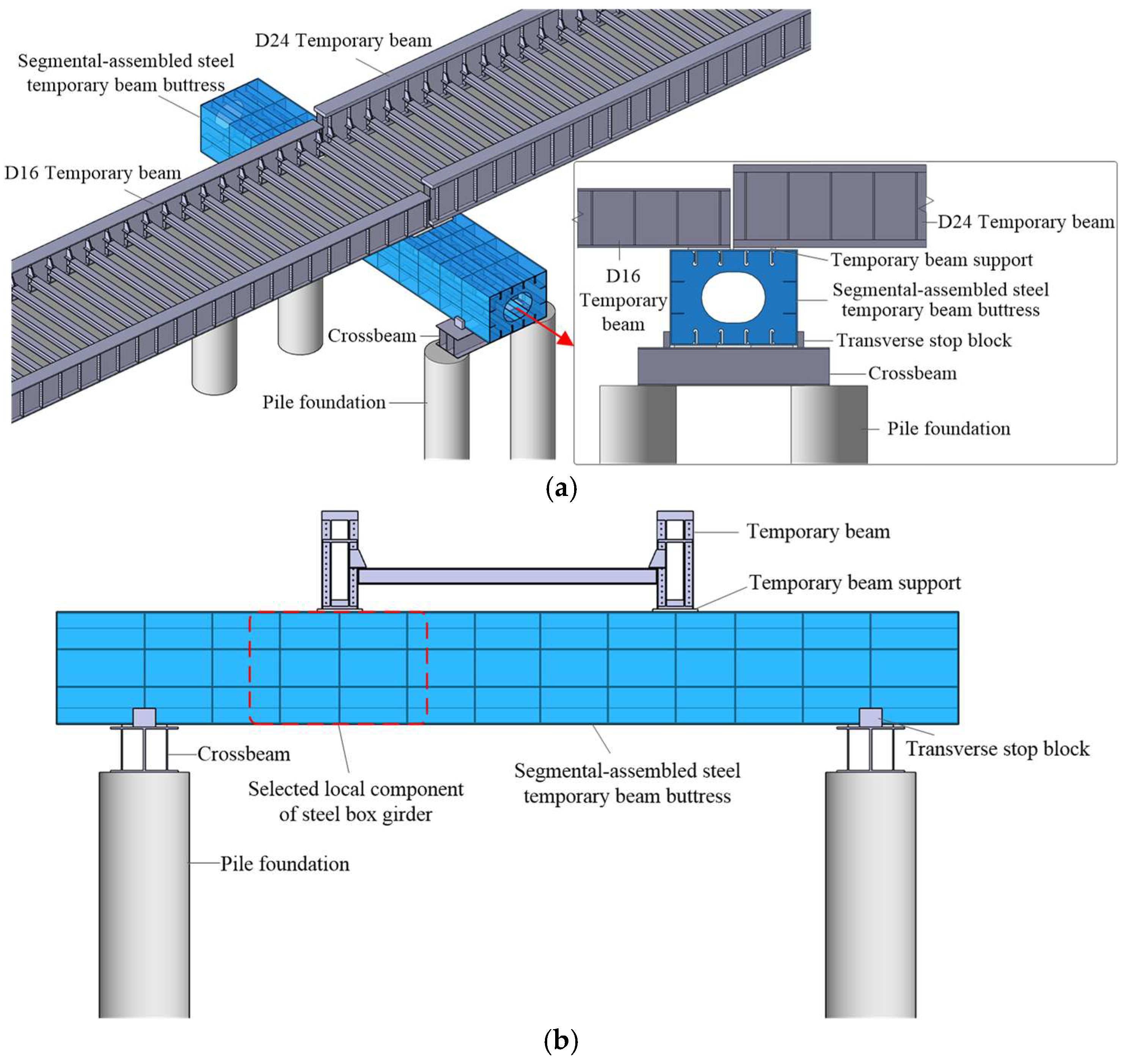
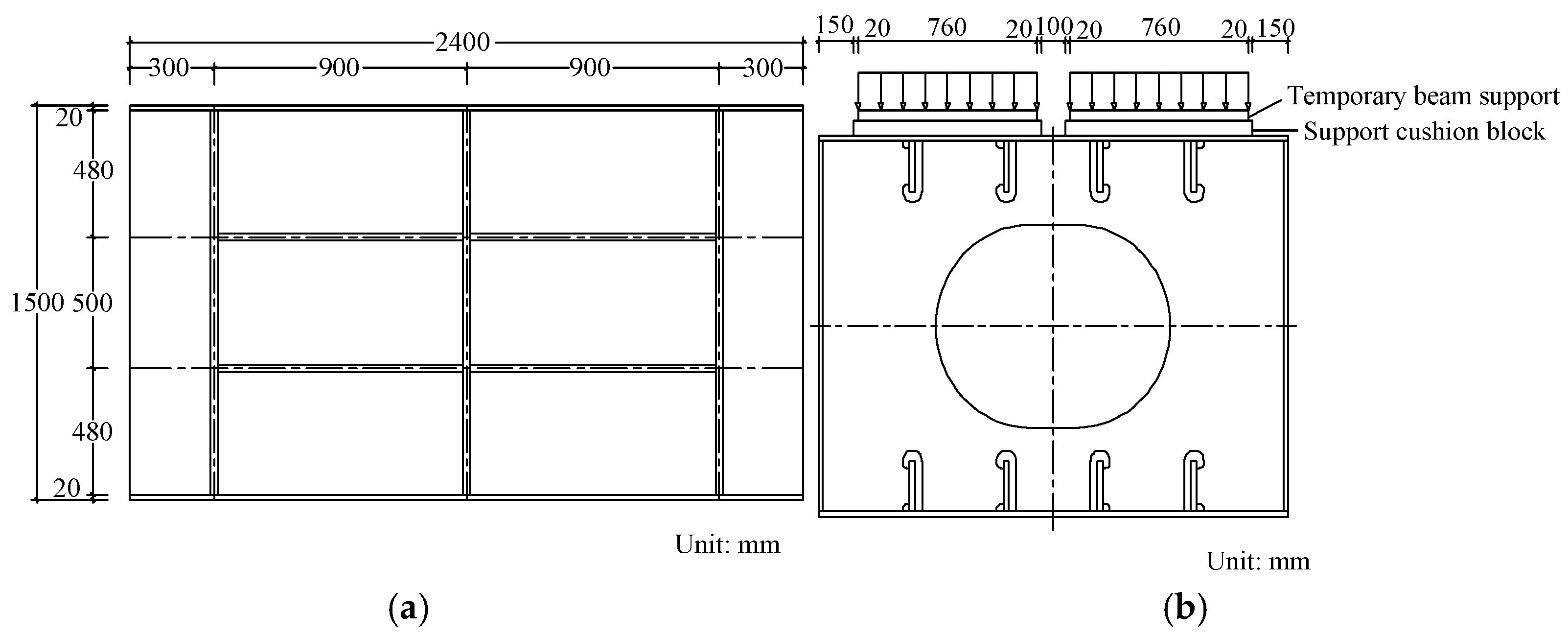
2.1. Overview of Steel Box Girder Local Component

In order to reduce the lifting weight for on-site construction, the steel temporary beam buttress adopts the segmental assembly form. Three precast segmental steel box girder members are assembled by high-strength bolts on site. In the operational state, the buttress bears the vertical load transmitted from two adjacent temporary beams, and the two ends of the buttress are supported on the lower crossbeams. The longitudinal force distribution of the entire structure is similar to a four-point bending beam, and there are two temporary beam supports at each vertical loading point, as shown in Figure 1a.
Due to the repeated recycling of the new segmental-assembled steel temporary beam buttress, in order to explore the fatigue performance of the welded joints of the segmental-assembled steel temporary beam buttress under long-term train loads, this paper selects the local component of the steel box beam near the upper support of the buttress for fatigue test research. According to the longitudinal influence line of fatigue stress at the welded joints, the total length of the selected local steel box girder component is 2400 mm, which includes three transverse buttress areas. The section height and width of the local component are 1500 mm and 2000 mm, respectively. The transverse diaphragm spacing is 900 mm. There are four longitudinal ribs horizontally, with a spacing of 400 mm between adjacent longitudinal ribs. The thickness of the mother plate is 20 mm, while the thickness of the longitudinal stiffeners and transverse diaphragms is 25 mm. The schematic diagram of the selected local component of the steel box girder is shown in Figure 1b.
The local component test model of the steel box girder in the new segmental-assembled steel temporary beam buttress adopts Chinese Q345 steel, with an elastic modulus of 210,000 MPa, Poisson’s ratio of 0.3, and a density of 7850 kg/m3. In order to reduce the stress concentration effect of the weld between the transverse diaphragm and the top plate, the connection weld seam between the transverse diaphragm and the longitudinal rib in the local component of the steel box girder is set on the outer side of the transverse diaphragm, and the keyhole is symmetrically arranged in a horizontal direction to enhance the support effect of the longitudinal rib on the top plate. The longitudinal ribs are disconnected at the transverse diaphragm positions, so that the transverse diaphragms can provide stronger bending resistance for the web plates. Full penetration welds are used to connect the four mother plates, while the remaining welds are fillet welds with a toe radius of 10 mm. According to reference [24], the intersecting weld of the component in this article belongs to the intersection of a continuous longitudinal web stiffener with a girder web and a discontinuous transverse web stiffener. This type of intersection weld has a low susceptibility to constraint-induced fractures; thus, the design is reasonable. The elevation schematic diagram of the local component is shown in Figure 2a. The cross-section schematic diagram of the local component of the steel box girder and the positions of the upper supports on the buttress are shown in Figure 2b. The size of the temporary beam support is 760 × 600 × 36 mm, and cushion blocks are set between the temporary beam support and the support buttress.

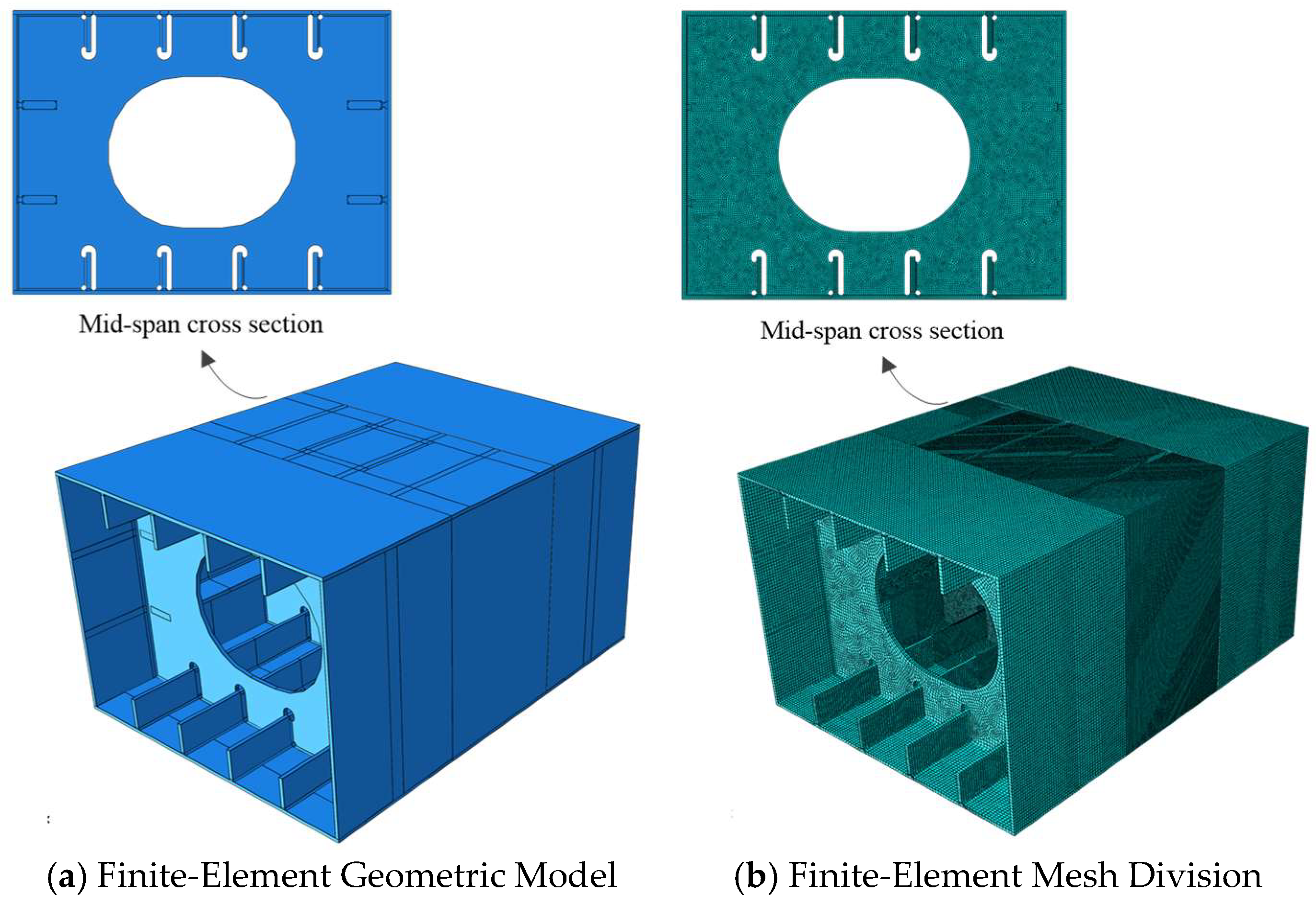
2.2. Numerical Simulation

In order to conduct a finite-element analysis of the fatigue performance of the local component of the steel box girder, a solid finite-element model of the test local component was established in the general finite-element software ABAQUS 6.21, as shown in Figure 3. All weld seams are modeled as solid elements according to their actual dimensions. The simply supported constraints were set below the transverse diaphragms on both sides of the local component. In order to facilitate the fatigue performance evaluation based on the hot-spot stress method, a high-order solid element C3D20R is established in this model to simulate various plates and welds. The size of the solid element is uniformly 10 mm.
Under the actual train load, the two temporary beam supports above the buttress transmit vertical forces with changing magnitude, while the laboratory can only use a single actuator for fatigue loading. Therefore, it is necessary to select an appropriate fatigue loading form based on the mechanical characteristics of the local component of the test steel box girder. Since the temporary beam buttress will generally experience two different forms of vertical load, which are the central load and the eccentric load, the mechanical behavior analysis of the local component model of the steel box girder under single central load and single eccentric load is carried out separately. The size of the loading area is set as 500 mm × 500 mm to simulate the size of the laminated rubber bearing used in the experiment. The central loading area is located at the center of the local component, while the eccentric loading area is located 250 mm away from the center point in the horizontal direction, as shown in Figure 4.
The welding joints in the local component of steel box girders mainly include the weld joint between the transverse diaphragm and the top plate, the welding joint between the transverse partition and the longitudinal ribs, and the welding joint between the longitudinal ribs and the top plate. The results show that under the central load, the local component is mainly in a compression state, and the level of principal tensile stress is very low. Large principal tensile stresses only occur at the utility hole and keyhole. The maximum value of the principal tensile stresses is 71.6 MPa. However, under the eccentric loading condition, the overall level of principal tensile stress at the welded joints is relatively high. The maximum principal tensile stress occurs at the weld toe edge between the transverse diaphragm and top plate weld near the support edge of the loading area, with a maximum value of 197.6 MPa. The principal tensile stress distribution in the eccentric loading position will be discussed later in Section 3.1. In order to study the fatigue performance of welded joints in steel box girders with open longitudinal ribs, the unfavorable eccentric loading condition was selected for fatigue loading in the experiment.

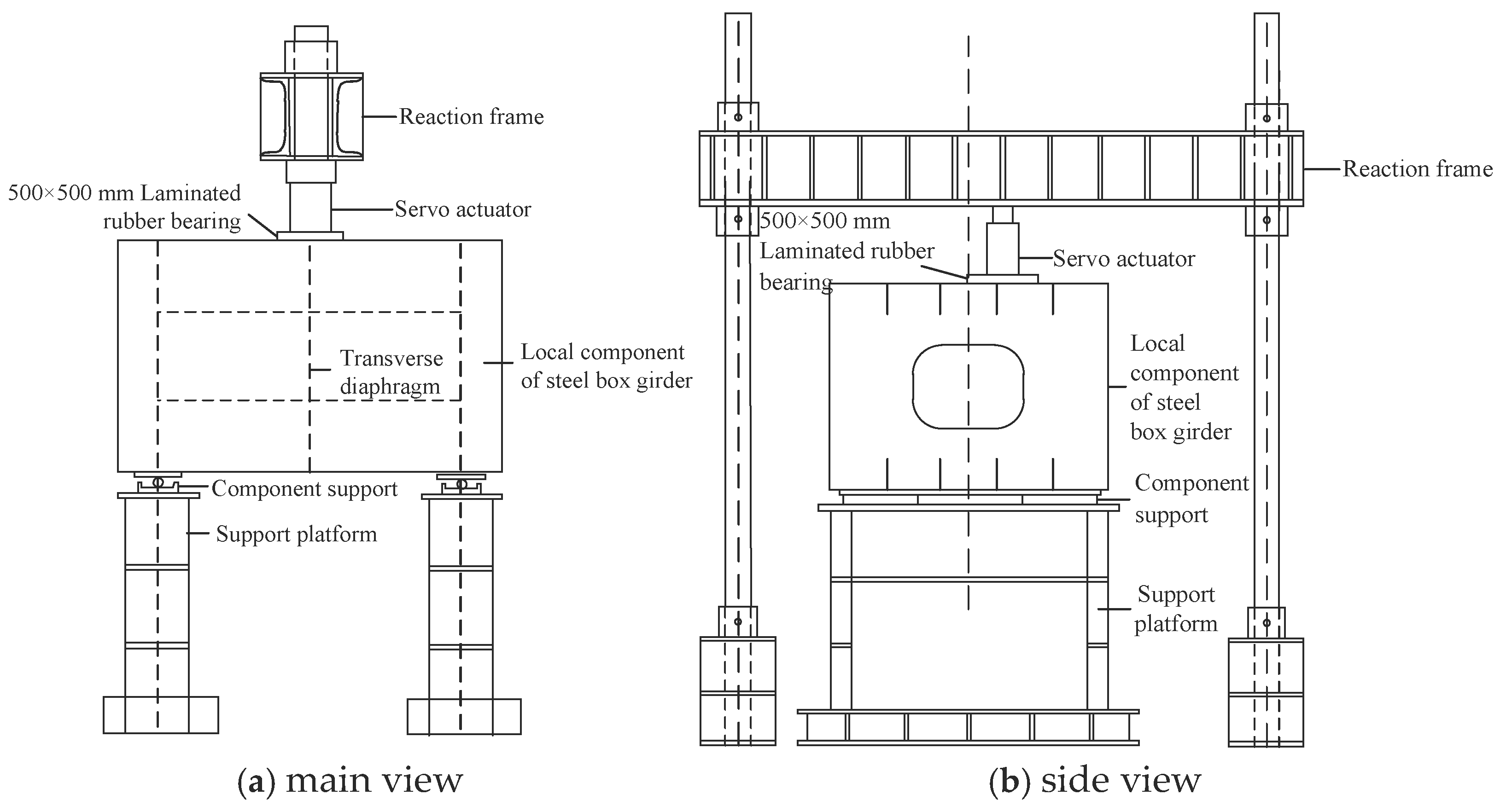
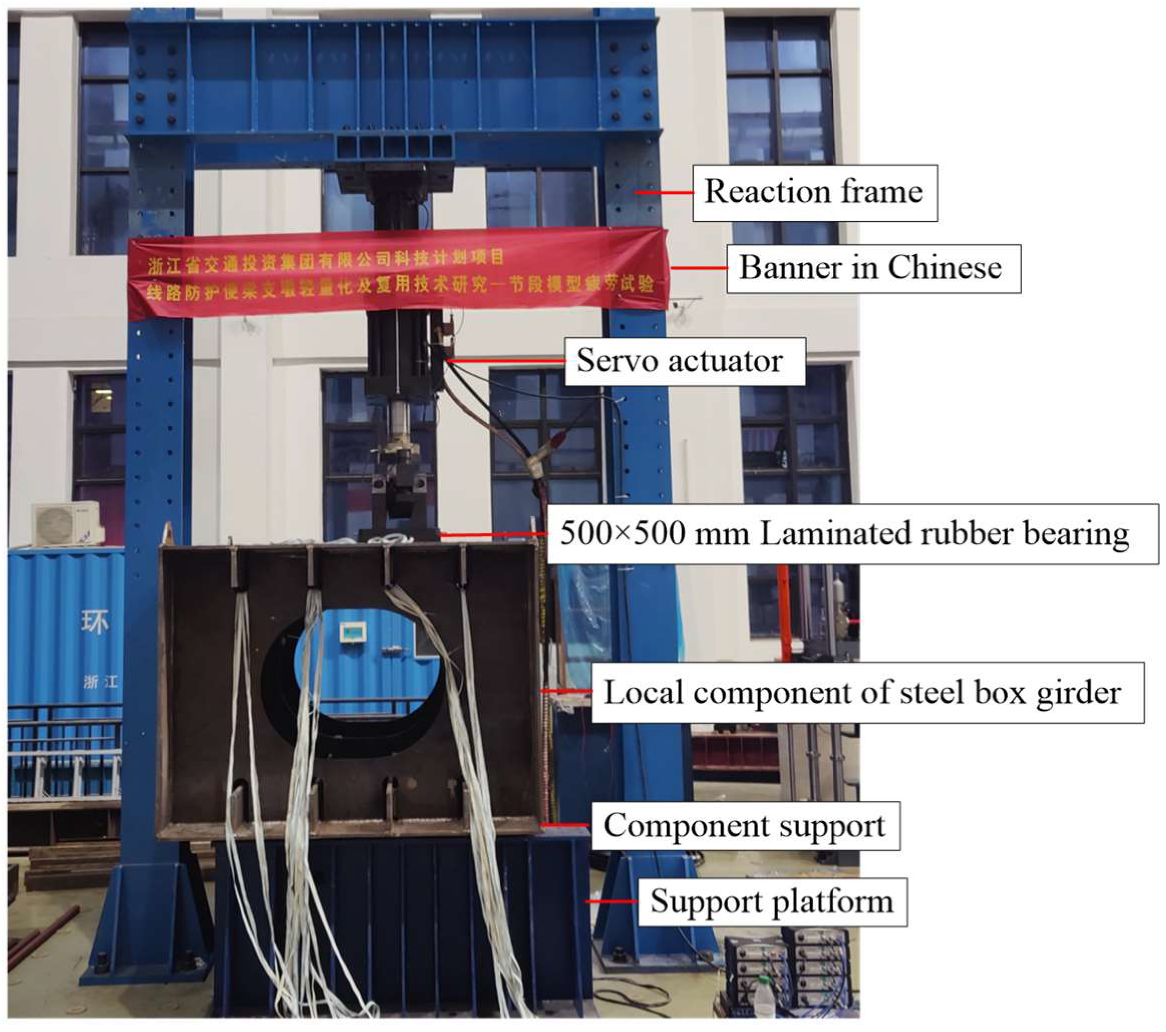
2.3. Fatigue Loading Test

This paper conducts fatigue performance tests on the local component of the steel box girder with open longitudinal ribs in the segmental-assembled steel temporary beam, as shown in Figure 1 and Figure 2, under the eccentric loading condition. The laboratory used a Bangwei MAD-1000 electro-hydraulic servo actuator (Hangzhou Bangwei Electromechanical Control Engineering Co., Ltd., Hangzhou, China) with a maximum vertical load of 100 tons and a 100-ton reaction frame for loading. The load size was directly read by the electro-hydraulic servo actuator, which had been calibrated by a force sensor before the test. The schematic diagram of fatigue test loading for the local component of the steel box girder is shown in Figure 5, and the on-site loading photo of the fatigue test is shown in Figure 6. Based on the stress results, the fatigue life prediction results obtained from the finite-element model in Section 2 and the laboratory test conditions, a three-stage loading system was employed for the fatigue test. That is, 500,000 cycles of fatigue loading with a load amplitude of 550 kN were carried out first, followed by 500,000 cycles of fatigue loading with a load amplitude of 750 kN, and the component was loaded with an amplitude of 950 kN until failure. The minimum load in the fatigue load cycle was 1 ton, and the maximum load is the sum of the load amplitude and the minimum load. The loading frequency corresponding to a load amplitude of 550 kN was 2.5 Hz, and the loading frequency for the subsequent two load amplitudes was 2.0 Hz. The fatigue loading test of the test components included a static load test and a fatigue test. The static load test was conducted after every 100,000 cycles of fatigue loading. The load intensity of the static load test is the fatigue load amplitude of the current loading stage.
According to the calculation results of the finite-element model, strain gauges were arranged at the three types of weld joints in the local components of the steel box girder, namely the weld between the transverse diaphragm and the top plate, the weld between the transverse diaphragm and the longitudinal rib, and the weld between the longitudinal rib and the top plate, to measure the nominal stress response results at these positions. Strain gauges are also arranged at the keyhole of the transverse diaphragm. The measuring point is arranged at a distance of 0.4 t from the edge of the weld toe [18], which is 10 mm. Among them, the nominal stress measuring point at the weld seam between the transverse diaphragm and the top plate, where the most unfavorable tensile stress may occur, is H5. The arrangement of stress measuring points for the local component of the steel box girder is shown in Figure 7. In order to obtain the hot-spot stress at the most unfavorable position, strain gauges were also arranged at the two linear extrapolation points of the transverse diaphragm and top plate welded joint, where the most unfavorable principal tensile stress may occur according to FE analysis. The stress measurement points corresponding to the hot-spot stress extrapolation points are H24 and H25, which are located 5 mm and 15 mm away from the weld toe edge, respectively. According to the generalized Hooke’s law and the formula for calculating principal tensile stress, the principal tensile stress at each measuring point can be obtained by measuring the positive strains εx and εy and the shear strain γxy of a single strain flower:
σ 1 = E 2 ε x + ε y 1 μ + 1 1 + μ ε x ε y 2 + γ x y 2

2.4. Fatigue Strength Evaluation Method

In this article, the nominal stress method and hot-spot stress method were employed to evaluate the fatigue strength of cracked welded joints based on the measured stress results obtained from finite-element analyses and fatigue tests. Further, an equivalent structural stress method was used based on finite-element analysis. The applicability of these three methods and the appropriate S-N curve parameters will be demonstrated.

2.4.1. Nominal Stress Method

The nominal stress refers to the average stress value distributed on the net area calculated by elastic theory at the location where cracks may occur near the base metal or weld seam. According to reference [18], the node stress at a distance of 0.4 t (t is the thickness of the transverse diaphragm or the longitudinal rib, which is 25 mm) from the weld toe, i.e., 10 mm, is taken as the nominal stress. This node is the outer node of the first element outside the weld toe in the finite-element model of this paper.

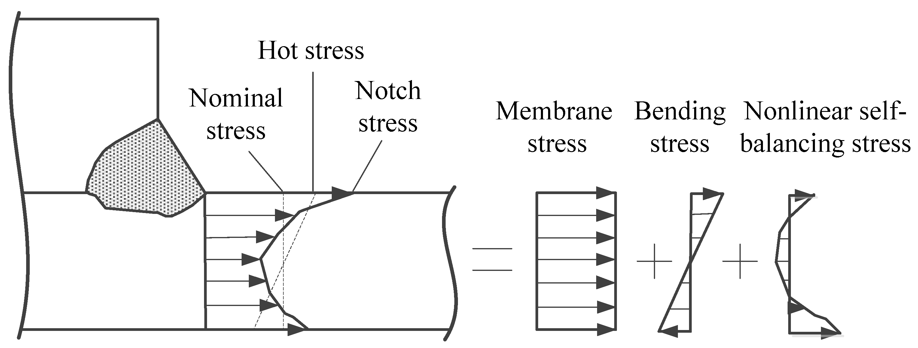
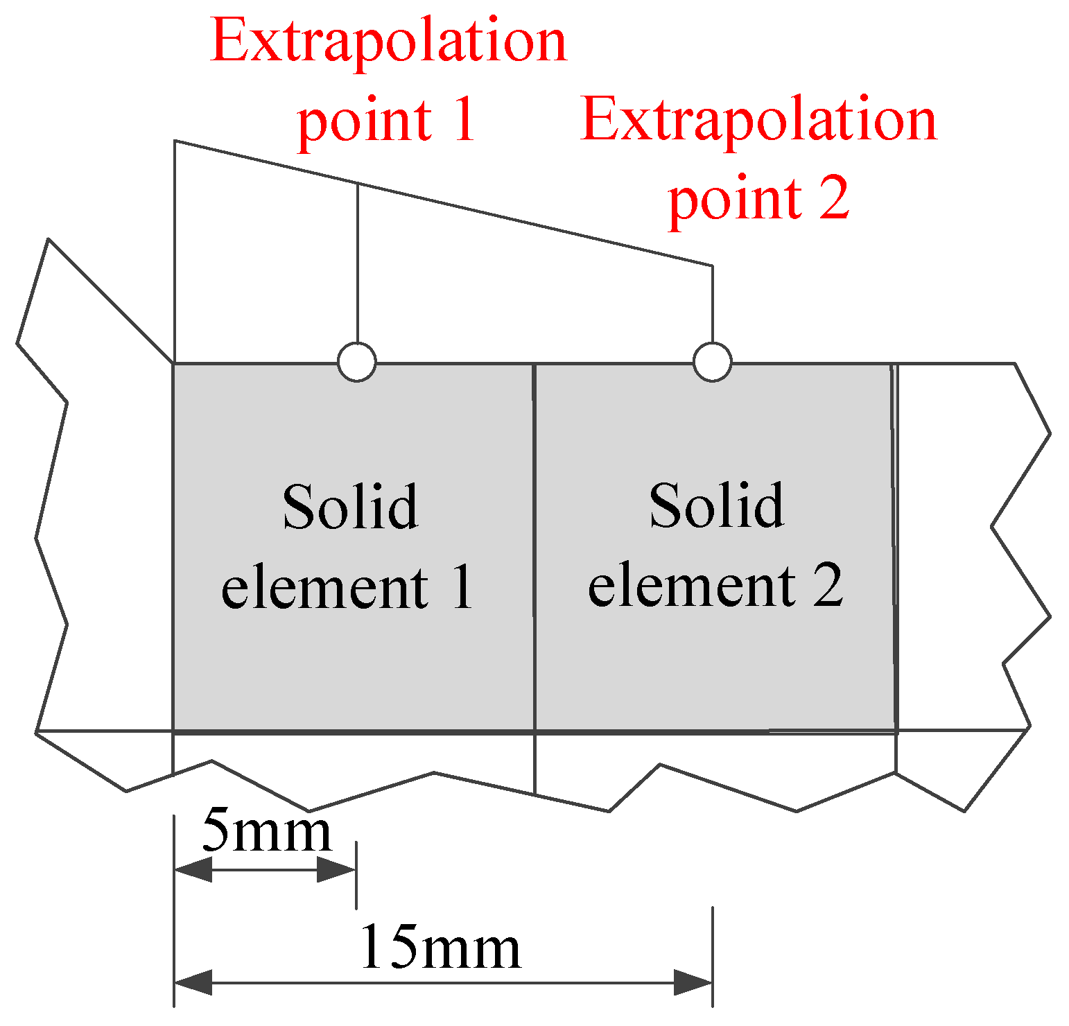
2.4.2. Hot-Spot Stress Method

According to existing literature research [14,17,18], the notch stress at the edge of the weld toe can be decomposed into membrane stress, bending stress, and nonlinear self-balancing stress caused by local notches, as shown in Figure 8. As already mentioned in the introduction, the hot-spot stress is the sum of the membrane stress and the bending stress.
The International Institute of Welding (IIW) [13] recommends taking into account the type of hot-spot stress when using the linear extrapolation method to calculate the hot-spot stresses. Among them, Class A hot-spot stress is located at the weld toe on the boundary between the plates or at the weld toe on the edge of the attached plate on the side of the mother plate, while Class B hot-spot stress is located at the weld toe on the edge of the attached plate on the side of the attached plate, as shown in Figure 9. IIW [13] stipulates that when the angle between the principal tensile stress and the normal of the weld seam is less than 60°, the principal tensile stress should be used as the hot-spot stress. When the angle between the tensile stress and the normal of the weld seam is greater than 60°, the hot-spot stress is the stress component perpendicular to the weld seam direction.
Under eccentric loading conditions, the maximum nominal stress of the steel box girders with open longitudinal ribs occurs near the weld toe on the edge of the attached plate on the side of the attached plate (discussed later, Section 3.1). The hot-spot stress at this position belongs to Class B hot-spot stress, and the angle between the principal tensile stress direction at this position and the normal of the weld seam is much smaller than 60°. For the finite-element model using 10 mm high-order solid elements in this article, the hot-spot stress can be calculated according to the following formula [16]:
σ h s = 1.5 σ 5 mm 0.5 σ 15 mm
where σhs is the value of the hot-spot stress, and σ5mm and σ15mm are the stresses in the two linear extrapolation points. The positions of the two linear extrapolation points are shown in Figure 10, which are the surface center points of the two solid elements outside the weld toe.

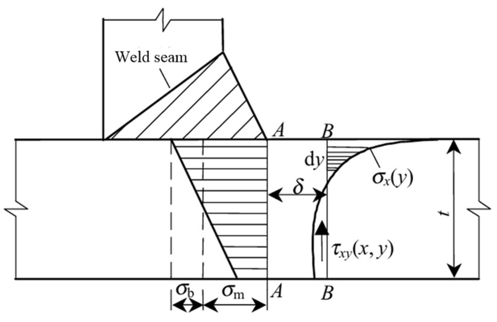
2.4.3. Equivalent Structural Stress Method

Based on the stress decomposition diagram in Figure 8, Dong et al. [14] proposed a structural stress solution method based on mechanical equilibrium relationships, namely the equivalent structural stress method. The schematic diagram of structural stress calculation in the equivalent structural stress method for the solid finite-element model is shown in Figure 11. The structural stress to be determined is located at the weld toe, i.e., point A. When the shear stress is ignored, the structural stress σs is the sum of the membrane stress σm and bending stress σb at this point. However, if the stress at that point is directly extracted, it includes nonlinear self-balancing stress caused by local notches, as shown in Figure 8. In order to indirectly obtain the membrane stress σm and bending stress σb, it is necessary to establish an equilibrium relationship between the A-A section and the B-B section. Among them, the force balance relationship in the direction perpendicular to the plate thickness is
σ m = 1 t 0 t σ x y d y
The moment balance relationship obtained by taking the moment at point A is
σ m t 2 2 + σ b t 2 6 = 0 t σ x y y d y + δ 0 t τ x y y d y
In the solid finite-element model, σm and σb can be obtained by calculating the line forces and line moments [23]. The equivalent structural stress evaluation method is applied based on the principal S-N curve, where the stress parameter of the principal S-N curve is expressed as the equivalent structural stress amplitude ΔSeq, i.e.,
Δ S e q = σ s t ( 2 n ) / 2 n I r 1 / n = C N h
I r = 0.0011 r 6 + 0.0767 r 5 0.0988 r 4 + 0.0946 r 3 + 0.0221 r 2 + 0.014 r + 1.2223
In the formula, n is the long crack propagation index, which is taken as n = 3.6 [25], and r is the bending stress ratio, calculated as r = σb/(σm + σb). I(r) is the load ratio coefficient, and I(r)1/n is the coefficient that modifies the loading mode by considering the load as the control condition. C and h are the constants that determine the main S-N curve. According to reference [25], C and h are determined as 19930.2 and 0.3195 for the average curve of the main S-N curve.

3. Results and Discussion

3.1. Finite-Element Analysis Results

The extraction results of nominal stress at each type of welding joint under a 550 kN eccentric load condition can be obtained. Among them, the weld between the transverse diaphragm and the longitudinal ribs is 14.37 MPa, the weld between the top plate and the longitudinal rib is 11.73 MPa, and the weld between the transverse diaphragm and the top plate is 99.83 MPa. Thus, the weld joint between the transverse diaphragm and the top plate is the most unfavorable type of weld joint in the segmental-assembled steel temporary beam buttress. In the finite-element analysis results, the principal tensile stress distribution of the transverse diaphragm in the mid-span cross-section under a test load amplitude of 550 kN is shown in Figure 12.
According to the Chinese Design Code for Highway Steel Structure Bridges (JTGD64-2015) [10], for the welds of orthotropic steel box girders with open longitudinal ribs, the S-N curve with a fatigue life of 2 million cycles at the nominal stress amplitude of 70 MPa is selected for fatigue strength evaluation. The results show that under the eccentric load of 550 kN, the weld joint between the transverse diaphragm and the top plate is the most unfavorable weld joint. According to the nominal stress method, the theoretical fatigue life of this joint is 689,500 times, which is listed in Table 1. The nominal stresses of the weld between the top plate and the longitudinal rib, as well as between the transverse diaphragm and the longitudinal rib, are lower than the fatigue cut-off limit. There is no risk of fatigue failure in these two kinds of welded joints.
In order to verify the applicability of the hot-spot stress method for the fatigue life assessment of welded joints in steel box girders with open longitudinal ribs, this paper extrapolates the hot-spot stress in the weld joints between the transverse diaphragm and top plate of the tested local component based on the finite-element model analysis results according to Equation (2). Referring to the parameter classification table of the hot-spot stress S-N curve recommended by IIW [13], the welded joint between the transverse diaphragm and the top plate belongs to the eighth type of welded joint, that is, the Class B welded joint with a long attached plate. The theoretical fatigue life of the welded joint between the transverse diaphragm and the top plate under eccentric load should be obtained according to the S-N curve corresponding to a fatigue life of 2 million times under a hot-spot stress amplitude of 90 MPa (i.e., FAT90), as shown in Table 1. The results show that the hot-spot stress at the most unfavorable welded joint of the steel box girder with open longitudinal ribs is 130 MPa, and the theoretical fatigue life obtained according to FAT90 is 663,600 times.
Although the effectiveness of the equivalent structural stress method in the fatigue performance evaluation of orthotropic steel bridge decks with closed longitudinal ribs has been proven, it has not yet been applied in steel box girders with open longitudinal ribs. In this section, the structural stress σs of the welded joint between the transverse diaphragm and the top plate and the theoretical fatigue life calculated according to Equations (5) and (6) are also given in Table 1.
It can be seen from Table 1 that the theoretical fatigue lives obtained by the nominal stress method and the hot-spot stress method are relatively close, while there is a certain difference in the calculation results between the equivalent structural stress and the two methods. The suitable fatigue assessment method and S-N curve for the fatigue of steel box girders with open longitudinal ribs need to be verified by a fatigue performance test of the local component of steel box girders.

3.2. Fatigue Performance in Test

To study the fatigue performance of welded joints, the nominal stress changes at each welded joint during each static load test were analyzed, and the crack development at key measuring points was focused on. Due to stress redistribution in the local area near the crack after fatigue cracking, according to reference [18], a 25% change in fatigue stress response value or direct observation of fatigue cracks can be used as a fatigue failure criterion. During the fatigue test loading process, the distribution of principal tensile stress was basically consistent with the finite-element prediction results, and the H5 measuring point showed the maximum principal tensile stress response. At the end of the first two stages of the experiment loading, which is the end of one million cycles, visible fatigue cracks appeared in the weld seam between the transverse diaphragm and the top plate near the H5 measuring point, as shown in Figure 13. Among them, the crack appearing in front of the weld seam between the transverse diaphragm and the top plate is an irregular curve with a length of 30.9 mm, while the rear crack is straight and has a length of 29.5 mm. The appearance of a through-weld crack indicates that the structure has undergone severe fatigue cracking failure at this welded point. The loading was terminated, and the third stage of fatigue loading was canceled.
The peak value of principal tensile stress in the static load tests after every 100,000 cycles of fatigue loading at each nominal stress measuring point of the weld seam, i.e., the variation curve of measured nominal stress amplitude with fatigue loading times, is shown in Figure 14. The figure also shows the variation curve of the corresponding nominal stress obtained by the finite-element model with the number of fatigue loading cycles, which has been introduced in Section 3.1. In the figure, H5 is the most unfavorable measuring point for the weld between the top plate and the transverse diaphragm, H9 is the most unfavorable measuring point for the weld between the transverse diaphragm and the longitudinal rib, and J4 is the most unfavorable measuring point for the weld between the top plate and the longitudinal rib. As shown in the figure, the initial stress of each measuring point is in good agreement with the finite-element calculation results, which shows that the finite-element model has high computational accuracy. In the actual engineering design process, the solid finite-element model can be constructed using the method described in this article. With the progress of fatigue loading, the measured static stress in the H5 measuring point decreases to a certain extent, while the measured stress of other measuring points remains basically unchanged. During the loading process with a fatigue load amplitude of 550 kN for the first 500,000 cycles, the measured stress drop at the H5 measuring point was relatively small. During the last 500,000 cycles of fatigue load with an amplitude of 750 kN, the stress at the H5 measuring point decreased significantly at 600,000 cycles, with a decrease greater than 25% of the initial stress value. This indicates a significant degradation of mechanical properties. Therefore, this moment was determined as the fatigue failure moment of the welded joint, and the number of fatigue failure times of the local component of the steel box girder in this test was 600,000.

3.3. Fatigue Strength Evaluation

According to the strain test results in three directions at the measuring point at the cracked welded joint in the static load test, the nominal stress amplitude and the stress amplitude at the extrapolation points of the hot-spot stress method can be calculated according to Equation (1), and the hot-spot stress amplitude can be further obtained according to Equation (2). Figure 15 shows the change histories of nominal stress amplitude and hot-spot stress amplitude at the cracked welded joint with the number of fatigue loading cycles. In Figure 15, the nominal stress and hot-spot stress amplitude variation records calculated by the finite-element model were plotted simultaneously. From the figure, it can be seen that the values of the hot-spot stress amplitudes are all greater than those of the nominal stress amplitudes, which is due to the fact that the hot-spot stress method considers the stress concentration effect. The variation trend in hot stress amplitude is similar to that of nominal stress amplitude, and there is also a significant decrease when the fatigue loading is carried out up to 600,000 times.
Based on the measured stress results, the fatigue strength evaluation of welded joints in the local component of the steel box girder was carried out using the nominal stress method, the hot-spot stress method, and the equivalent structural stress method. Based on Miner’s linear cumulative damage theory, the fatigue strength under 2 million equal-amplitude loads is calculated based on the fatigue damage of the first 600,000 variable-amplitude loading cycles:
Δ σ c = n i Δ σ i m N D 1 / m
In the formula, Δσc is the fatigue strength calculated using the nominal stress method and the hot-spot stress method. ND is the number of actions corresponding to the constant stress amplitude Δσc, which is taken as 2 million times. ni is the number of fatigue loading cycles within the stress range σi, which can be obtained from Figure 15. m is the slope of the S-N curve in double logarithmic coordinates. Furthermore, based on the finite-element stress calculation results in the first 600,000 times, the fatigue strength based on the finite-element method can also be calculated according to Equation (7). The nominal stress method and hot-spot stress method fatigue strength obtained from experimental measurements and finite-element calculations are shown in Table 2. The results indicate that although the calculated and measured stresses are close in the initial state, the measured stress results gradually decrease with the progress of fatigue cycle loading, and the fatigue strength obtained from the measured stress results is lower than that obtained from the FE results. The fatigue strength calculated by the nominal stress method and the hot-spot stress method according to the FE model is 72.1 MPa and 93.8 MPa, respectively. When evaluating the fatigue performance of welded joints in steel box girders with open longitudinal ribs through finite-element calculations, it is reasonable to select the S-N curves with a fatigue strength of 70 MPa and 90 MPa (FAT90) corresponding to the nominal stress method and the hot-spot stress method, respectively. Due to the inability to measure the equivalent structural stress in the test, only the fatigue strength of the equivalent structural stress method based on finite-element stress results is given in Table 2, with a magnitude of 94.1 MPa. The result is close to the result of the hot-spot stress method and slightly lower than the fatigue strength corresponding to 2 million cycles calculated according to the main S-N curve, which is 99.8 MPa. However, it is within the range of twice the standard deviation curve (the fatigue strength corresponding to 2 million cycles is 69.5 MPa).

4. Conclusions

This article takes a new type of segmental-assembled steel temporary beam buttress as the engineering background and focuses on the fatigue performance and evaluation method of the local component of steel box girders with open longitudinal ribs under cyclic loads. The FE calculation and fatigue loading test were carried out, and the accuracy of the FE model was verified by comparing it with the test results. The rationality of the fatigue strength evaluation method for welded joints was further explored, and the following conclusions were obtained:
(1)
According to the results of the FE analysis, eccentric loading was determined as the unfavorable fatigue condition of the welded joints of the steel box girder with open longitudinal ribs after fatigue optimization design. In the experiment, the eccentric load condition was selected for fatigue loading.
(2)
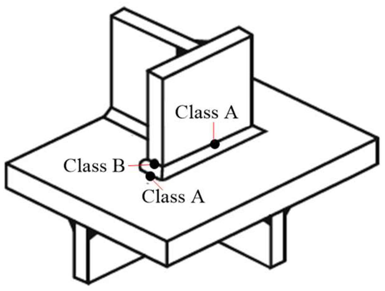
The maximum nominal stress occurs at the edge of the weld toe between the transverse diaphragm and the top plate at the support edge of the load area, which is the fatigue-vulnerable position of the component. The nominal stresses of the weld between the transverse diaphragm and the longitudinal ribs, as well as the weld between the top plate and the longitudinal ribs, are very low.
(3)
The fatigue strengths corresponding to 2 million cycles of the nominal stress method and the hot-spot stress method, calculated based on the finite-element model and the number of experimental fatigue failure cycles, are 72.1 MPa and 93.8 MPa, respectively. It is reasonable to use the nominal stress S-N curve with a fatigue life of 2 million cycles at 70 MPa and the hot-spot stress S-N curve with a fatigue life of 2 million cycles at 90 MPa (FAT90) for the fatigue evaluation of welded joints in the fatigue design of steel box girders with open longitudinal ribs.
(4)
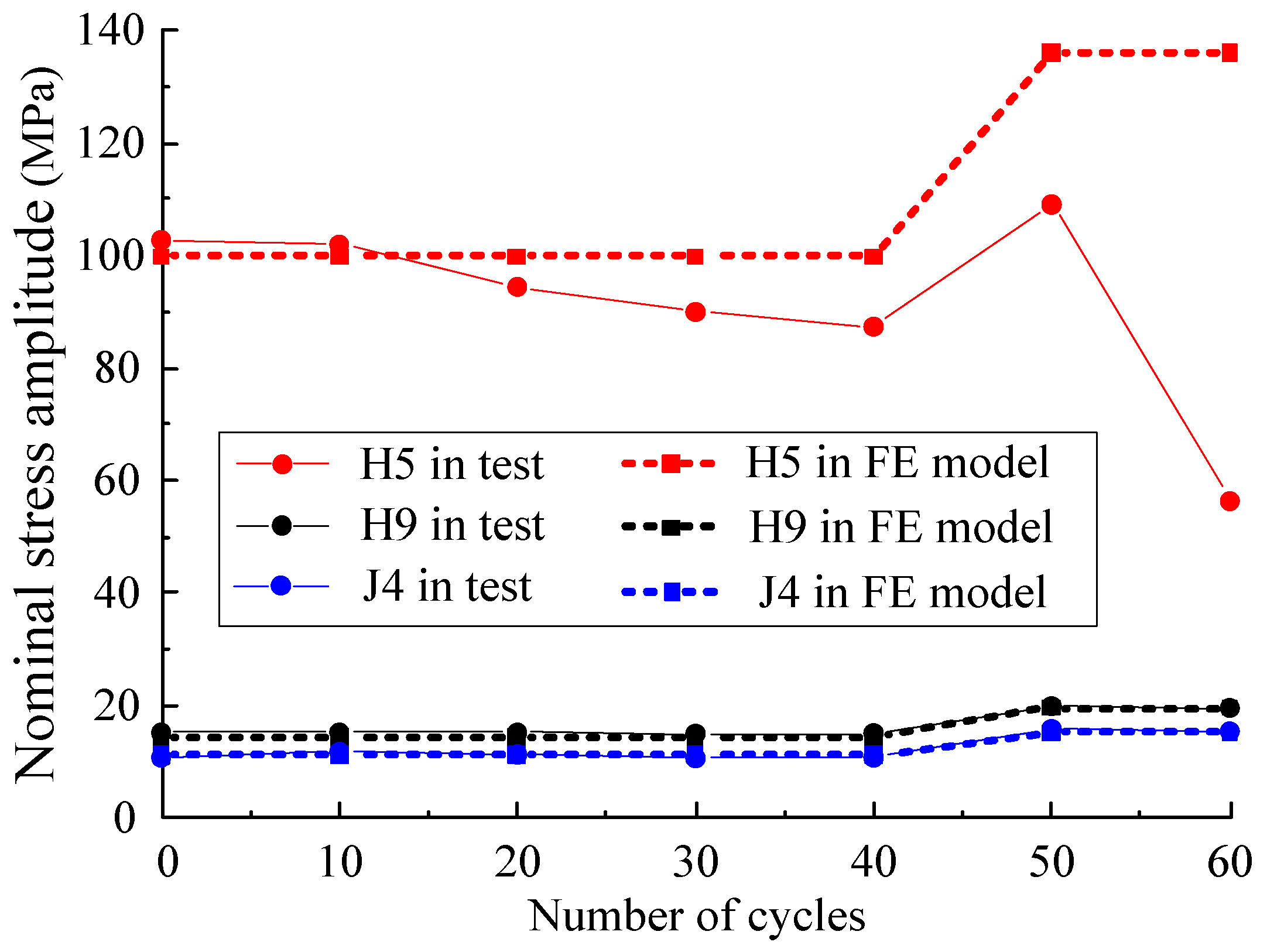
The initial stress of each measuring point is in good agreement with the finite-element calculation results. The static load measured stress of the fatigue-vulnerable position measuring point shows a certain decrease, while the stress of the other measuring points remains basically unchanged. Fatigue cracks penetrating the weld seam appeared at the fatigue-vulnerable position, and the number of fatigue failure cycles of the test component was 600,000.
(5)
Based on the slope of the main S-N curve in the equivalent structural stress method, the fatigue strength corresponding to 2 million cycles calculated by the finite-element model is 94.1 MPa, which is close to the results of the hot-spot stress method. This result is slightly lower than the corresponding result of the main S-N curve but within the range of two standard deviations of the curve. The equivalent structural stress method is applicable for evaluating the fatigue performance of steel box girders with open longitudinal ribs.
This paper mainly conducts research on fatigue strength assessment methods and the corresponding S-N curve parameters of steel box girders with open longitudinal ribs. In addition, due to the singularity of this fatigue loading test, the influence of factors such as welding residual stresses, steel corrosion effects, and construction errors on the fatigue performance of components was not considered.

Author Contributions

Conceptualization, B.S. and M.L.; methodology, Y.W.; software, H.Z.; validation, B.S., Y.W. and H.Z.; formal analysis, M.L.; investigation, Y.W.; resources, B.S.; data curation, M.L.; writing—original draft preparation, H.Z.; writing—review and editing, Y.W.; visualization, H.Z.; supervision, B.S.; project administration, B.S.; funding acquisition, Y.W. and H.Z. All authors have read and agreed to the published version of the manuscript.

Funding

The study described in this paper was supported by the programs of Science and Technology Plan Project of Zhejiang Provincial Transportation Investment Group Co., LTD (Grant No. 202304) and National Natural Science Foundation of China (Grant No. 52308537).

Data Availability Statement

All data, models, or code that support the findings of this study are available from the corresponding author upon reasonable request.

Acknowledgments

The support of fundings is gratefully acknowledged by the authors. The authors would like to express their gratitude to Dassault Systèmes Simulia Corporation for allowing the use of their powerful commercial FE package—ABAQUS 6.21—during this research.

Conflicts of Interest

Authors Bo Shen and Ming Liu are employed by the company Zhejiang Railway Investment Construction Engineering Co., Ltd. The remaining authors declare that the research was conducted in the absence of any commercial or financial relationships that could be construed as a potential conflict of interest.

References

  1. Zhang, Q.H.; Li, J.; Guo, Y.W.; Yuan, D.Y.; Bu, Y.Z. Fatigue Failure Modes and Resistance Evaluation of Orthotropic Steel Bridge Deck Structural System. China Civ. Eng. J. 2019, 52, 71–81. (In Chinese) [Google Scholar] [CrossRef]
  2. Zhang, Q.H.; Cui, C.; Bu, Y.Z.; Li, Q. Study on Fatigue Features of Orthotropic Decks in Steel Box Girder of Hong Kong-Zhuhai-Macao Bridge. China Civ. Eng. J. 2014, 47, 110–119. (In Chinese) [Google Scholar] [CrossRef]
  3. Zhang, Q.H.; Zhang, P.; Liu, Y.; Yu, J.; Ye, Z.T. Study on Fatigue Performance of Orthotropic Composite Bridge Deck with Large Longitudinal Ribs. China J. Highw. Transp. 2017, 30, 226–235. (In Chinese) [Google Scholar] [CrossRef]
  4. Zhang, Q.H.; Li, J.; Yuan, D.; Zhu, J.Z.; Cui, C. Fatigue Model Tests of Orthotropic Steel Bridge Deck of Shenzhen-Zhongshan Link. China Civ. Eng. J. 2020, 53, 102–115. (In Chinese) [Google Scholar] [CrossRef]
  5. Ju, X.C. Experimental Study on Fatigue Performance of Full Penetration Welded Joints of U-shaped Rib-plate. China J. Highw. Transp. 2019, 32, 176–183. (In Chinese) [Google Scholar] [CrossRef]
  6. Heng, J.; Zheng, K.; Gou, C.; Zhang, Y.; Bao, Y. Fatigue Performance of Rib-to-deck Joints in Orthotropic Steel Decks with Thickened Edge U-ribs. J. Bridge Eng. 2017, 22, 04017059. [Google Scholar] [CrossRef]
  7. Zhang, S.; Shao, X.; Cao, J.; Cui, J.; Hu, J.; Deng, L. Fatigue Performance of a Lightweight Composite Bridge Deck with Open Ribs. J. Bridge Eng. 2016, 21, 04016039. [Google Scholar] [CrossRef]
  8. Ma, G.M.; Jin, X.N.; Li, W.X.; Zhao, Y.W. Research on Propagation Characteristics of Fatigue Crack for steel Bridge Decks with Open-Shaped Longitudinal Ribs. Ind. Constr. 2021, 51, 100–105. (In Chinese) [Google Scholar] [CrossRef]
  9. Xu, X.L.; Qian, S.B.; Li, H.T.; Wu, C.; Wang, R.G.; Li, Q.; Ding, X.G.; Li, Z.J.; Li, X.H. Comparative Test Study on Fatigue Performance of New Orthotropic Steel Bridge Decks with Open-Shaped Longitudinal Ribs. China Civ. Eng. J. 2025, 58, 50–67. (In Chinese) [Google Scholar] [CrossRef]
  10. Ministry of Transport, PRC. JTG D64-2015; Specifications for Design of Highway Steel Bridge. China Communications Press: Beijing, China, 2015. (In Chinese)
  11. National Railway Administration of the People's Republic of China. TB 10091-2017; Code for Design on Steel Structure of Railway Bridge. China Railway Publishing House: Beijing, China, 2017. (In Chinese)
  12. EN 1993-1-9; Eurocode 3: Design of Steel Structures, Part1-9: Fatigue Strength of Steel Structures. CEN: Brussels, Belgium, 2005.
  13. Intemational Institute of Welding. Recommendations for Fatigue Design of Welded Joints and Components; IIW document IIW-2259-15ex XIII-2460-13/XV-1440-13; Springer International Publishing: Cham, Switzerland, 2014. [Google Scholar]
  14. Dong, P. A structural stress definition and numerical implementation for fatigue analysis of welded joints. Int. J. Fatigue 2001, 23, 865–876. [Google Scholar] [CrossRef]
  15. American Society of Mechanical Engineers. Boiler and Pressure Vessel Code, Section III, Rules for Construction of Nuclear Power Plant Components, NB, Class 1 Components and Section VIII, Rules for Construction of Pressure Vessels; Division 2—Alternate Rules, American Society of Mechanical Engineers: New York, NY, USA, 1997. [Google Scholar]
  16. Zhang, Q.H.; Wei, C.; Xu, Z.; Yang, C.; Zhang, C.Q.; Cui, C. Experimental Study on Fatigue Performance of Integral Welded Joints in Steel Truss Bridges. China J. Highw. Transp. 2022, 35, 77–90. (In Chinese) [Google Scholar]
  17. Cui, C.; Liu, Y.M.; Liao, G.X. Fatigue Evaluation Approaches of Welded Joints on Orthotropic Steel Bridge Deck. J. Southwest Jiaotong Univ. 2015, 50, 1011–1017. (In Chinese) [Google Scholar] [CrossRef]
  18. Zhang, Q.H.; Da, L.T.; Li, J.; Wang, K.; Yuan, D.; Cui, C.; Bu, Y. Fatigue Resistance of an Innovative Rib-to-deck Both-sides Welded Joint in Orthotropic Steel Bridge Deck. China Civ. Eng. J. 2022, 35, 162–174. (In Chinese) [Google Scholar] [CrossRef]
  19. National Railway Administration of the People’s Republic of China. TB 10002-2017; Code for Design on Railway Bridge and Culvert. China Railway Publishing House: Beijing, China, 2017. (In Chinese)
  20. National Railway Administration of the People’s Republic of China. TB 10092-2017; Code for Design of Concrete Structures of Railway Bridge and Culvert. China Railway Publishing House: Beijing, China, 2017. (In Chinese)
  21. Wang, Z.H.; Fang, Y.W.; Zhu, Z.B.; Huang, M.Q.; Wang, Y. Mechanical Performance Analysis of Bolted Steel Joints for New Prefabricated Railway Beam Steel Support Piers. Bull. Sci. Technol. 2024, 40, 89–96. (In Chinese) [Google Scholar]
  22. Huang, M.Q.; Wang, Y.; Shen, B.; Jia, Y.Q.; Wang, Z.H. Research on Ultimate Bearing Capacity and Mechanical Properties of New Steel Piers for Railway. J. Heilongjiang Inst. Technol. 2024, 38, 16–23. (In Chinese) [Google Scholar] [CrossRef]
  23. Dong, P.; Hong, J.K. The master S-N curve approach to fatigue of vessel and piping welds. Weld. World 2004, 48, 28–36. [Google Scholar] [CrossRef]
  24. Coletti, D.A.; Ream, A.P.; Chavel, B.W. Evaluation of Steel Bridge Details for Susceptibility to Constraint-Induced Fracture. Transp. Res. Rec. J. Transp. Res. Board 2022, 2679, 93–103. [Google Scholar] [CrossRef]
  25. Dong, P.; Prager, M.; Osage, D. The design master S-N curve in Asme Div 2 rewrite and its validations. Weld. World 2007, 51, 53–63. [Google Scholar] [CrossRef]
Figure 1. Overall mechanics schematic diagram of the new segmental-assembled steel temporary beam buttress and selected local component of the steel box girder. (a) Overall mechanics schematic diagram of the new segmental-assembled steel temporary beam buttress; (b) selected local component of the steel box girder.
Crystals 15 00646 g001
Figure 2. Schematic diagram of a partial component of a steel box girder. (a) Elevation view. (b) Cross-sectional view and positions of the upper supports on the buttress.
Crystals 15 00646 g002
Figure 3. Finite-element calculation model of local component of steel box girder.
Crystals 15 00646 g003
Figure 4. Central and eccentric loading position.
Crystals 15 00646 g004
Figure 5. Schematic diagram of fatigue test loading for the local component of the steel box girder.
Crystals 15 00646 g005
Figure 6. On-site loading photo of fatigue test.
Crystals 15 00646 g006
Figure 7. Layout of stress measuring points for local component of steel box girder. (a) Transverse diaphragm stress measuring points. (b) Longitudinal stiffening rib stress measuring points.
Crystals 15 00646 g007
Figure 8. Schematic diagram of principal tensile stress decomposition at the weld toe.
Crystals 15 00646 g008
Figure 9. Determination of hot-spot stress types.
Crystals 15 00646 g009
Figure 10. Hot-spot stress extrapolation points of the solid finite-element model.
Crystals 15 00646 g010
Figure 11. Schematic diagram of structural stress calculation for solid finite-element model.
Crystals 15 00646 g011
Figure 12. Principal tensile stress distribution of the transverse diaphragm in the mid-span cross-section (unit: MPa).
Crystals 15 00646 g012
Figure 13. Fatigue cracks at the weld joint between the transverse diaphragm and the top plate.
Crystals 15 00646 g013
Figure 14. Nominal stress amplitude histories of weld joints.
Crystals 15 00646 g014
Figure 15. Change histories of nominal stress amplitude and hot-spot stress amplitude in cracked weld joint.
Crystals 15 00646 g015
Table 1. Nominal stress, hot-spot stress, structural stress, and corresponding theoretical fatigue lives at the welding joint between the transverse diaphragm and the top plate under eccentric loading conditions with a load amplitude of 550 kN.
Fatigue Assessment MethodCorresponding Stress Obtained by FE Analysis (MPa)Theoretical Fatigue Life
Nominal stress method99.83689,500
Hot-spot stress method130.05663,600
Equivalent structural stress method128.02918,600
Table 2. Weld fatigue strength obtained by different fatigue evaluation methods.
Fatigue Assessment MethodFatigue Strength Obtained from Test (MPa)Fatigue Strength Obtained from FE Model (MPa)
Nominal stress method65.772.1
Hot-spot stress method82.593.8
Equivalent structural stress method/94.1
Disclaimer/Publisher’s Note: The statements, opinions and data contained in all publications are solely those of the individual author(s) and contributor(s) and not of MDPI and/or the editor(s). MDPI and/or the editor(s) disclaim responsibility for any injury to people or property resulting from any ideas, methods, instructions or products referred to in the content.

