Article

The Temperature Sensitivity of the Piezoelectric Thickness Shear Mode of α-GeO2 Single Crystals

Institut Charles Gerhardt de Montpellier, University of Montpellier, Centre National de la Recherche Scientifique, Ecole Nationale Supérieur de Chimie de Montpellier, 34095 Montpellier, France
*
Author to whom correspondence should be addressed.
Crystals 2025, 15(7), 613; https://doi.org/10.3390/cryst15070613
Submission received: 23 May 2025 / Revised: 19 June 2025 / Accepted: 23 June 2025 / Published: 30 June 2025
(This article belongs to the Section Crystal Engineering)

Abstract

This paper focuses on identifying temperature-compensated Y-cuts (using a Cartesian coordinate system) in a piezoelectric α-GeO2 single crystal, which is isostructural–quartz α-SiO2. The study aims to minimize the frequency drift of the thickness shear mode by analyzing the resonant frequency’s first- and second-order temperature coefficients Tf(1) and Tf(2). To obtain these, the first-order, TCij(1), and second-order, TCij(2), temperature coefficients of the elastic constant, Cij, previously obtained from room temperature up to 900 °C, were calculated. Upon heating, the thermal behavior of the elastic constants indicated that some, such as C11 and C33, are stable over a range of temperatures, while others, such as C44 and C66, increase with the temperature. This paper also explores a family of singly and doubly rotated Y-cuts of α-GeO2, revealing cuts with a potential application for temperature compensation and/or linear dependence over the temperature range. The results are compared with those of the well-known piezoelectric isomorph material α-SiO2. The findings highlight that α-GeO2 is a promising material for piezoelectric devices in high-temperature environments, outperforming α-SiO2 (α-quartz), which is limited by a solid–solid phase transition at 573 °C.

1. Introduction

Piezoelectric single crystals with a stable non-centrosymmetric hexagonal crystal structure have been studied extensively for a range of applications, including non-linear optics, surface acoustic wave sensors, and filter and frequency control [1,2,3,4,5]. In the α-quartz-like family (P3221 or P3121 space groups) with TO2 (T = Si, Ge) and MXO4 compounds (M = B, Al, Ga, Fe, Mn; X = P, As), the piezoelectric coupling factor k strongly depends on the structural distortion, and it has been shown that one of the most distorted and, thus, most promising piezoelectric materials is GeO2 [6,7,8,9]. Using a high-temperature flux growth method, centimeter-sized α-GeO2 single crystals that are thermally stable up to a melting temperature of 1116 °C were grown [10,11,12,13,14]. Their piezoelectric properties were measured in relation to the heating temperature on crystallographically oriented plates [15]. α-GeO2 belongs to the trigonal crystal system, and its material properties are crystal-orientation-dependent. Using a Cartesian coordinate system, the three principal axes, X, Y, and Z, were chosen such that the threefold symmetry axis is along Z (this axis of the coordinate system coincides with the natural c axis of the crystal), the twofold axis is along X, and Y is perpendicular to both X and Z. The plates that cut perpendicularly to the X, Y, and Z directions are known as the X-, Y-, and Z-cuts, respectively [16].
α-GeO2, as a material with a α-quartz-like structure, only has two independent piezoelectric strain constants: d11 and d14 [16]. It has been shown that their room-temperature experimental values are higher than those of quartz α-SiO2, and their piezoelectric response is still present at T = 600 °C, creating interesting possibilities for this material [15]. Indeed, even if single-crystal α-quartz is the most commonly used material for piezoelectric resonators, its transformation to the β-quartz structure near 573 °C limits its application under stress conditions, such as high temperatures.
Among the five basic vibration modes that can be excited by an electric field (converse piezoelectric effect) in class 32 crystals, there is a family of rotated Y-cuts (singly and doubly rotated) in α-quartz that exhibits zero temperature coefficients [16,17,18,19,20,21,22]. For these Y-rotated cuts, the resonant frequency of the thickness shear mode does not drift with a temperature change, which, for sensor applications, provides accurate and reliable measurements over a wide range of operating temperatures (around the temperature where the first-order temperature coefficient is canceled). Furthermore, piezoelectric materials in high-temperature applications require precise knowledge of the evolution of the resonant frequency over different ranges of temperatures [23,24,25,26].
The main purpose of this paper is to investigate/predict the existence of temperature-compensated cuts of an α-GeO2 single crystal for use in high-temperature bulk acoustic wave (BAW) signal-processing devices, which are superior to α-quartz.

2. Methodology

The search for temperature-compensated cuts, which allow for the development of devices with resonance frequencies that do not drift with temperature changes, requires the following:
Determining, based on experimental measurements, the curves of the evolution of elastic constants as a function of the temperature, as well as the first- and second-order temperature coefficients.
Researching and calculating the temperature-compensated cut angles of Y-plates in single and double rotations within a temperature range of 25–900 °C.
Examining the effect of rotation on Y-plates on the emergence of parasitic vibration modes.

2.1. First- and Second-Order Temperature Coefficients of the Resonant Frequency

To predict the variation in the frequency response of resonators in relation to the temperature, it is common to use the first-order, T f ( 1 ) , and second-order, T f ( 2 ) , temperature coefficients, which are defined, respectively, by the following: T f ( 1 ) = 1 f d f d T and T f ( 2 ) = 1 2 f d 2 f d T 2 . Here, f is the resonant frequency and T is the temperature. T f ( 1 ) quantifies the rate of change in the resonant frequency, f , of the resonator in relation to the temperature, T . Understanding and controlling this temperature dependence is essential for achieving stable and precise frequency performance due to the inherent properties of the crystal material. If the goal is to minimize the frequency drift of the sensor across the operating temperature range, the first-order temperature coefficient helps in selecting the appropriate crystal cut to improve the temperature stability. While the first-order coefficient describes the linear change in frequency with temperature, the second-order temperature coefficient, T f ( 2 ) , provides information about how this change varies non-linearly. Knowing this coefficient allows for the selection/design of α-GeO2 cuts that minimize non-linear temperature effects (which is crucial in applications requiring very high stability over a broad temperature range). Moreover, knowledge of this coefficient helps in designing compensation circuits or using temperature control methods to counteract non-linear frequency shifts.
For an unrotated Y-cut α-GeO2 plate, the resonant frequency, f, of the thickness shear mode is given by [22] f = 1 2 t C 66 D ρ , where t is the thickness of the α-GeO2 plate, ρ is the density, and C 66 D is the piezoelectrically stiffened elastic constant, which governs the shear motion around Z for the Y-cut (the tensor stiffness C i j k l is converted to the matrix stiffness C I J , where I, J = 1–6). The relation between the stiffened elastic constant, C 66 D , and the pure elastic constant, C 66 E , for the thickness shear mode of a single class 32 crystal is [16] C 66 D = C 66 E + e 11 2 ε 11 x , where e 11 is the piezoelectric coefficient and ε 11 x is the elastically clamped dielectric permittivity. Nevertheless, for materials with weak electromechanical coupling, such as α-GeO2, only the temperature coefficients of the elastic constant, T ( n ) C I J , and thermal expansion, T ( n ) α , are significant, because the piezoelectric and dielectric constants generally have a smaller effect on the temperature response of devices using a piezoelectric material [11]. In the following, the exponents D and E for the calculations of temperature coefficients will no longer be used.
The first-order temperature coefficient, T f ( 1 ) , of the thickness shear mode resonant frequency of a α-GeO2 Y-cut plate is
T f ( 1 ) = 1 f d f d T = 1 t d t d T + 1 2 C 66 d C 66 d T 1 2 ρ d ρ d T
The changes in the thickness, t, and density, ρ, are controlled by the thermal expansion coefficients, and because α-GeO2 is trigonal, there are two independent thermal expansion coefficients [18], α 11 = α 22 and α 33 . We can write the following:
1 ρ d ρ d T = 2 α 11 + α 33
For the thickness shear mode, the controlling dimension is the thickness, t, measured in the Y direction, and the temperature change of t is based on the thermal expansion coefficient, so that
1 t d t d T = α 22 = α 11
The second-order temperature coefficient, T f ( 2 ) , of the thickness shear mode resonant frequency of a α-GeO2 Y-cut plate is
1 2 f d 2 f d T 2 = T f ( 2 ) = 3 8 α 33 T C 66 ( 1 ) 1 4 T C 66 1 2 + 1 2 T C 66 2 + 3 2 α 11 2 + 3 8 α 33 2 + α 11 α 33
with T C 66 ( 1 ) and T C 66 ( 2 ) being, respectively, the first- and second-order temperature coefficients of the elastic constant, C66.
Taking the order of magnitude of the thermal expansion of α 11   a n d   α 33 , which is ~10−6 (°C−1), into account, the equation of T f ( 2 ) can be written as follows:
T f ( 2 ) 1 4 T C 66 ( 1 ) 2 + 1 2 T C 66 ( 2 )

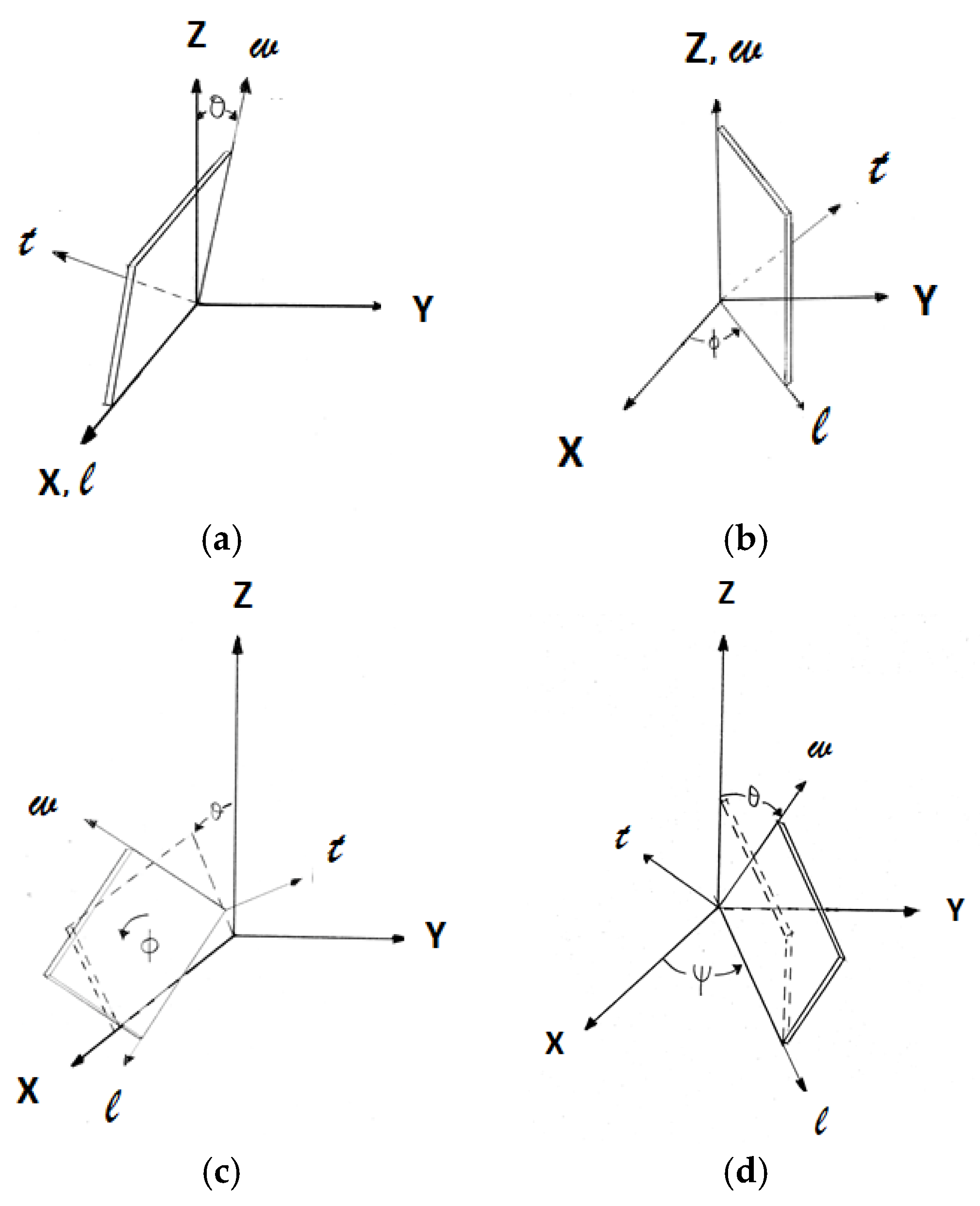
2.2. Rotated Y-Cut Plates

In a rotated coordinate system, all the dielectric, elastic, and coupling constants are noted with a single prime (′) to indicate a first rotation and with a double prime (″) to indicate a second rotation. The initial position of the plate is aligned with the X-, Y-, and Z axes.
A singly rotated Y-cut plate—a Y-cutting plate that undergoes a single rotation of an angle θ around the X axis—is noted as (YXl) θ in standard notation [16], as illustrated in Figure 1a, where the symbols l, w, and t denote the length, width, and thickness of the plate. A Y-cutting plate rotated at an angle ϕ around the Y axis, shown in Figure 1b, is noted as (YXt) ϕ. The rotation angles are positive for a counter-clockwise rotation and negative for a clockwise one. In a singly rotated Y-cut, the electric field E 2 along Y′ excites a thickness shear vibration through the relation x 6 = d 26 E 2 , with x 6 = x 12 + x 21 ,   which indicates the shear strain around Z′ (the shear motion is centered around Z′, while the electric field is in the Y′ direction). However, this applied electric field also excites a face shear vibration through d 25 . Depending on the geometric dimensions of the singly rotated Y-plate, this last mode can have a much lower resonant frequency than the thickness shear mode. Nevertheless, care must be exercised when establishing the harmonics of the resonant frequency of face shear vibration to avoid interferences with the thickness shear mode resonant frequency.
A Y-cutting plate which undergoes a double rotation is noted as (YXlt) θ/ϕ (Figure 1c) for a first rotation of θ about the X axis (X, Y, Z transform to X′ = X, Y′, Z′) followed by a second rotation of ϕ about the Y′ axis (X′, Y′, Z′ transform to X″, Y″ = Y′, Z″). (YXwl) ψ/θ (Figure 1d) is a doubly rotated Y-plate with a first rotation of ψ about the Z axis (X, Y, Z transform to X′, Y′, Z′ = Z), followed by a second rotation of θ about the X′ axis (X′, Y′, Z′ transform to X″ = X′, Y″, Z″). For a doubly rotated cut, the electric field E 2 along Y″ excites a thickness shear vibration through the relation x 6 = d 26 E 2 , with x 6 = x 12 + x 21   being the shear strain about Z″. In the same way, as for a singly rotated cut, there are harmonics of the resonant frequency of the face shear vibration through d 25 , and the correct geometric dimensions are required to avoid interferences between the fundamental thickness shear vibration and the induced face shear vibration.

2.3. Elastic Constants of Rotated Y-Cut Plates

2.3.1. Elastic Constants of a Singly Rotated Y-Cut Plate

α-GeO2 belongs to trigonal point group 32 with six independent stiffness coefficients, each with a different temperature coefficient. For singly rotated plates (YXl) θ or (YXt) ϕ, the resonant frequency of the thickness shear mode of vibration depends on the thickness of the α-GeO2 plate, its density, ρ , and the elastic coefficient, C 66 , which governs the shear motion about Z′. C 66 is related to the “new” coordinate system, which is obtained by rotating the “old” coordinate system about the X = [100] axis (rotation of θ about X) or the Y = [010] axis (rotation of ϕ about Y). The two sets of axes are related by nine-direction cosines, aij, where i, j = 1, 2, 3.
In tensor notation, the elastic coefficients are given by
C 66 = C 1212 = a 1 i a 2 j a 1 k a 2 l C i j k l
Converting back to the matrix form, and noting that C 55 = C 44 and C 56 = C 65 = C 14 for point group 32, we finally find for a Y-cut plate (YXl) θ that
C 66 = s i n 2 θ C 44 + 2 s i n θ c o s θ C 14 + c o s 2 θ C 66
with the direction cosine matrix (a) for a rotation of θ around the X axis being equal to
( a ) = 1 0 0 0 cos θ sin θ 0 sin θ cos θ
For a Y-cut plate (YXt) ϕ, we have the following:
C 66 = s i n 2 ϕ C 44 + c o s 2 ϕ C 66
with the direction cosine matrix (a) for a rotation of ϕ around the Z axis being defined by
( a ) = cos ϕ 0 sin ϕ 0 1 0 sin ϕ 0 cos ϕ
The only elastic constants for the thickness shear mode in the Y′ direction are C 14 , C 44 , and C 66 (see Equation (2)) for the rotated plate (YXl) θ, and C 44 and C 66 for (YXt) ϕ (Equation (3)).

2.3.2. Elastic Constants of a Doubly Rotated Y-Cut Plate

For doubly rotated Y-cut plates (YXlt) θ/ϕ or (YXwl) ψ/θ, the resonant frequency of the thickness shear mode depends on the thickness, the density, and the elastic constant, C 66 . We have the following:
C 66 = C 1212 = a 1 i a 2 j a 1 k a 2 l C i j k l
We find that, for a Y-cut plate (YXlt) θ/ϕ (Figure 1c), with the direction cosine matrix (a) being the product of the two individual rotations, a X for a rotation of θ about the X axis, followed by a Y and then a rotation of ϕ about Y′, the following applies:
( a ) = a Y a X = cos ϕ sin ϕ sin θ sin ϕ cos θ 0 cos θ sin θ sin ϕ cos ϕ sin θ cos ϕ cos θ
Then,
C 66 = ( s i n 2 ϕ c o s 2 θ s i n 2 θ ) C 11 ( 2 s i n 2 ϕ c o s 2 θ s i n 2 θ ) C 13 + s i n 2 θ c o s 2 ϕ + s i n 2 ϕ cos 2 θ C 14 + ( s i n 2 ϕ c o s 2 θ s i n 2 θ ) C 33 + s i n 2 ϕ c o s 2 2 θ + s i n 2 θ c o s 2 ϕ C 44 + ( c o s 2 θ c o s 2 ϕ ) C 66
For this doubly rotated Y-cut, if the direction of the plane wave propagation remains in the Y″Z″ plane (it moves along Y″ = Y′), C 66 depends on all the elastic constants: C 11 , C 13 , C 33 , C 14 , C 44 , and C 66 .
For a Y-cut plate (YXwl) ψ/θ (Figure 1d), the direction cosine matrix (a) is the product of the two individual rotations, a Z for a rotation of ψ about the Z axis, followed by a X for a rotation of θ about X′:
a i j = a i j X a i j Z = cos ψ sin ψ 0 sin ψ cos θ cos ψ cos θ sin θ sin ψ sin θ cos ψ sin θ cos θ
Then,
C 66 = s i n θ c o s θ 2 c o s 3 ψ 6 c o s ψ s i n 2 ψ C 14 + s i n 2 θ C 44 + c o s 2 θ C 66
For this doubly rotated Y-cut, if the direction of the plane wave propagation remains in the Y″Z″ plane (it moves along Y″), C 66 depends only the elastic constants C 14 , C 44 , and C 66 .

3. Results and Discussion

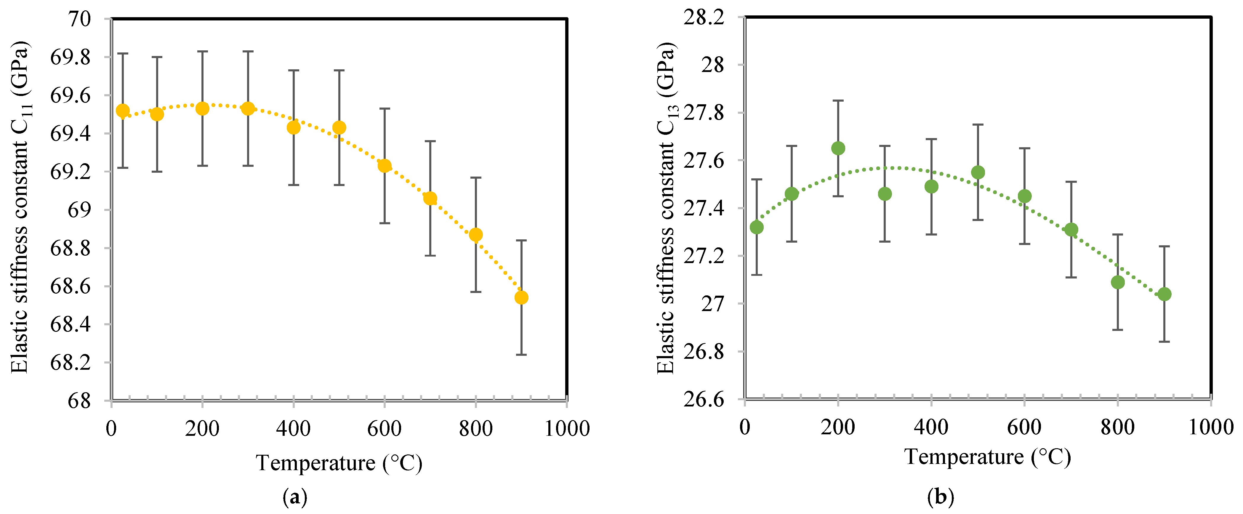
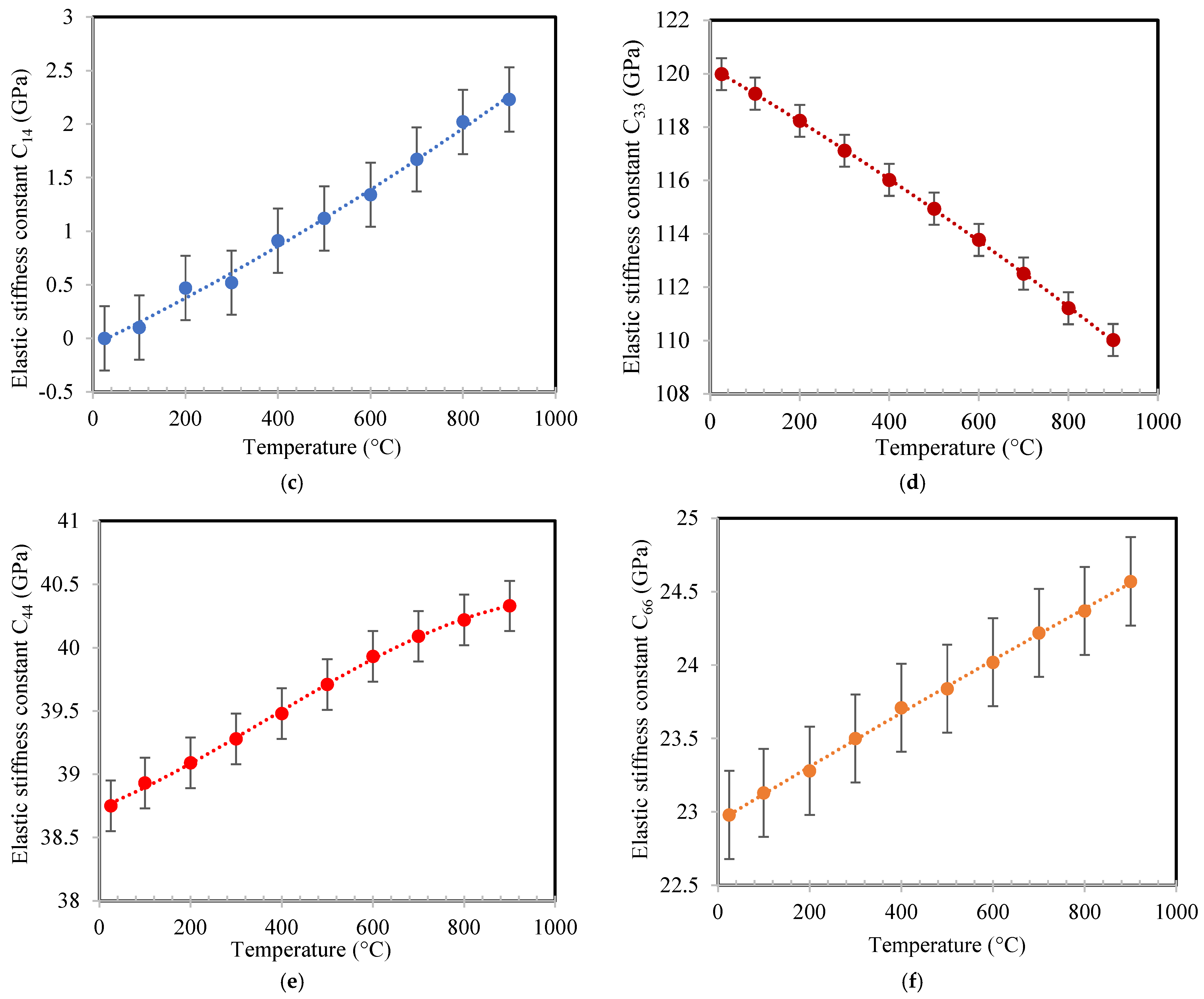
3.1. Temperature-Dependent Elastic Constants of α-GeO2

Second-order elastic constants can be obtained by measuring the sound velocity, ν, along the different crystallographic directions of a given crystal. The temperature-dependent sound velocity, translated in the α-GeO2 single crystal, was previously obtained through the Brillouin shift, ΔνB, registered at λ = 514.5 nm in the [25–900 °C] temperature range [27]. Figure 2a–e and f report the values of elastic constants in the temperature range of [25–900 °C]. Table 1 presents the equations of the fitting curve (polynomial regression) that were obtained from the data displayed in Figure 2.
From Figure 2, it can be noted that the elastic constant, C11, is stable up to 500 °C before slightly decreasing (variation of −1%) up to 900 °C (Figure 2a), while C13 evolves between 27 and 27.6 Gpa over the entire range of temperatures (Figure 2b). C33, the highest elastic constant value, decreases almost linearly by 8% (Figure 2d), while C44 (Figure 2e) and C66 (Figure 2f) increase, respectively, by 4% and 7%. The value of the elastic constant C14 (Figure 2c) is very low compared with the others. As can be seen in Table 2, it is almost zero at room temperature and has a value of only 2.04 Gpa at 900 °C. This needs to be emphasized when comparing this room-temperature value with that given for α-SiO2 in Table 3 [17]. Indeed, for the plane wave propagation in the Y direction that is generated by an applied electric field in the same direction, the general solution for class 32 is achieved by solving the Christoffel equations [16]. If, for α-SiO2, the solution is nontrivial [16]—resulting in the propagation of three waves in the Y direction (i.e., one stiffened piezoelectric transverse wave, one pseudo-longitudinal, and one pseudo-transverse elastic wave)—for α-GeO2, where the elastic coefficient is C 14 0 from the three elastic waves traveling along the Y direction, then we have one stiffened piezoelectric transverse wave that is polarized along X and traveling with the speed v = C 66 ρ , one purely elastic longitudinal wave traveling with the speed v = C 11 ρ , and one purely elastic transverse wave that is polarized along the Z direction and traveling with the speed v = C 44 ρ .
Nevertheless, C 14 increases with the temperature (Figure 2c) for α-GeO2; even if its value remains low in comparison to its other elastic constants (see Table 2), the last two elastic waves become increasingly pseudo-longitudinal and pseudo-transverse with increasing temperatures.
In Table 3, the values of the elastic constants and the calculated first- and second-order temperature coefficients of these elastic constants at 25 °C, 500 °C, and 900 °C are reported. By comparing the first- and second-order temperature coefficients of α-SiO2 and α-GeO2 at room temperature in Table 3, significant differences appear: opposite signs appear in front of the first-order temperature coefficients of C11, C13, and C44, while the same applies to the second-order temperature coefficients of C44 and C66. This clearly shows that the temperature behavior of α-GeO2 will be different from that observed for α-SiO2, which is limited to 573 °C (phase transition). This underlines the interest in looking for temperature-compensated cuts and/or linear dependences over the entire temperature range for this piezoelectric material.

3.2. Cuts with Zero Temperature Coefficients

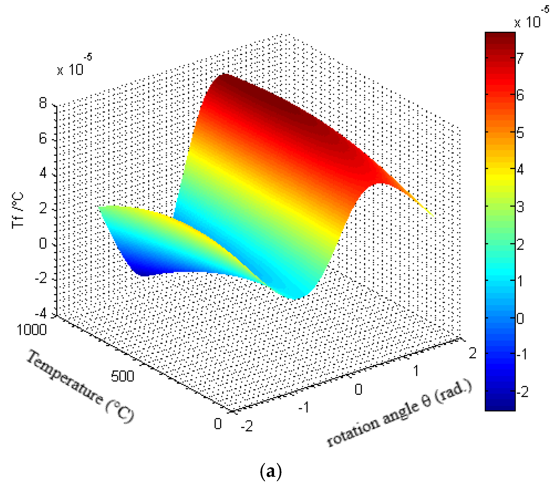
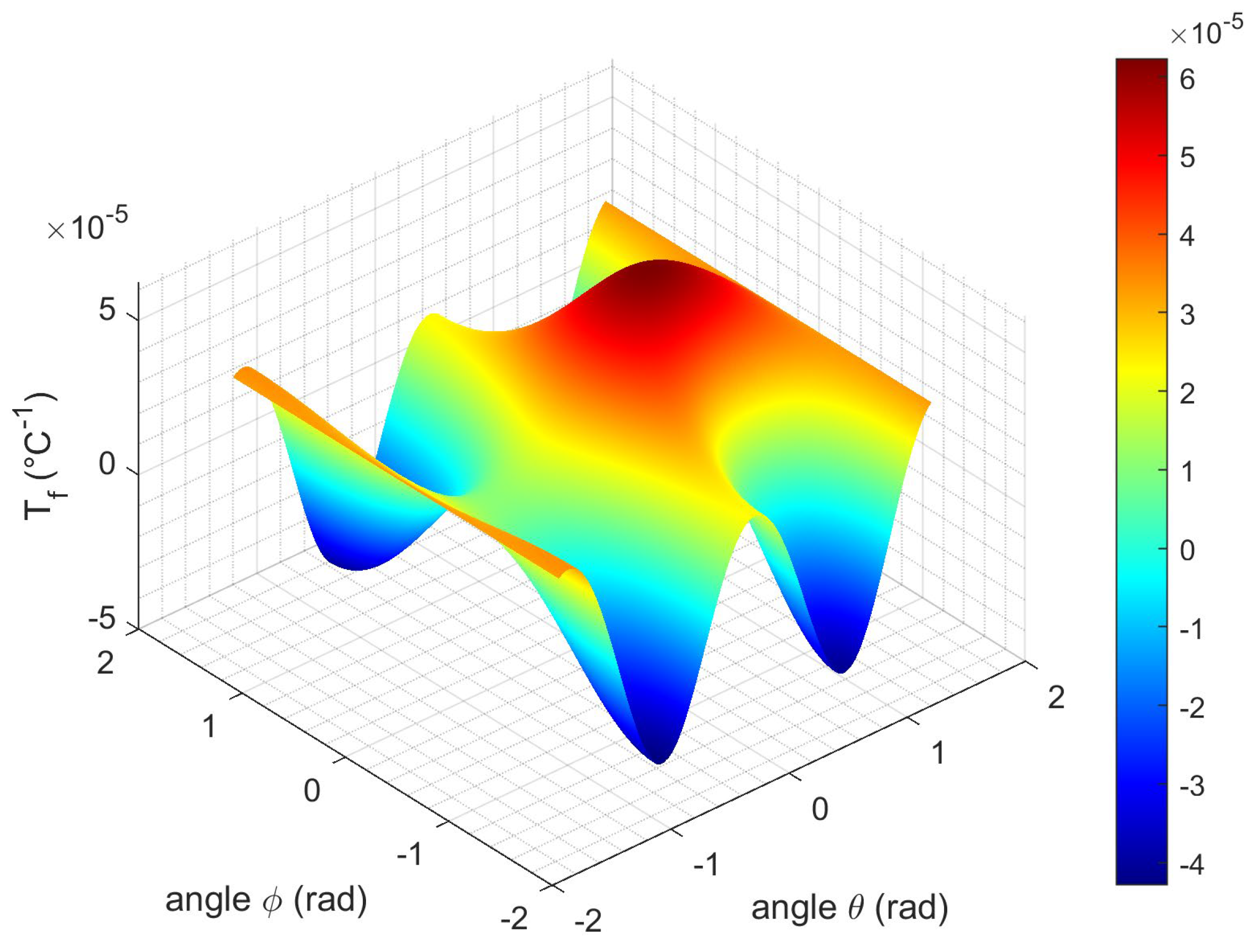
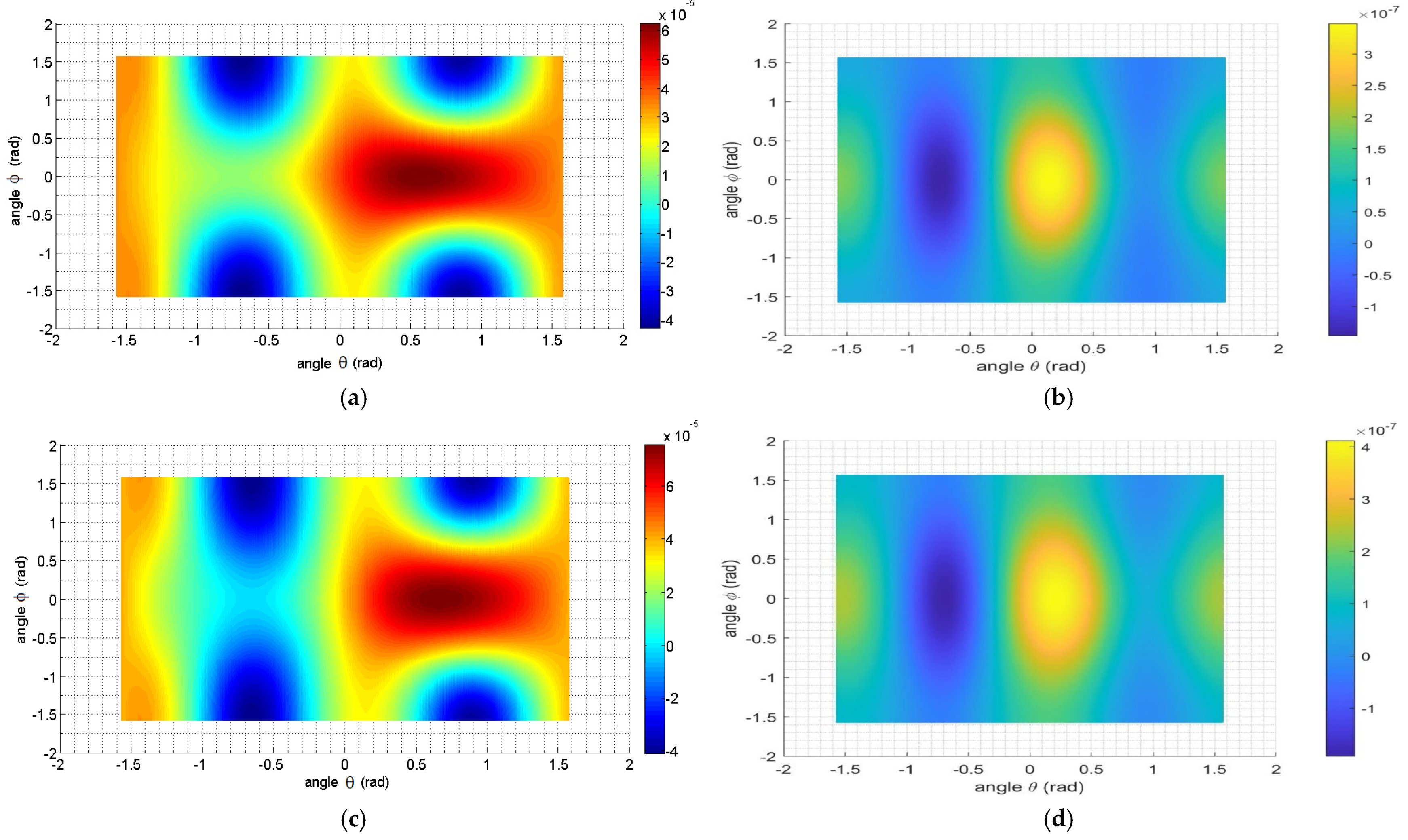
3.2.1. Singly Rotated Y-Cut Plate

For a singly rotated Y-cut (Yxl) θ, the thickness shear mode is driven by a piezoelectric coefficient d 26 , where
x 6 = d 26 E 2
and the resonant frequency is given by f = 1 2 t C 66 ρ , where C 66 is the elastic coefficient which governs the shear motion about Z′ for the rotated Y-cut. The first-order temperature coefficient of f is
T f ( 1 ) = 1 f d f d T = 1 t d t d T + 1 2 C 66 d C 66 d T 1 2 ρ d ρ d T
and the temperature change of t (thickness) is
1 t d t d T = α 22 = α 11 c o s 2 θ + α 33 s i n 2 θ
Taking the temperature derivative of C 66 (given by Equation (6)) and substituting the values into the equation for the first-order temperature coefficient of the resonant frequency gives the following:
1 f d f d T = α 11 c o s 2 θ α 33 s i n 2 θ + 1 2 s i n 2 θ C 44 T C 44 1 + 2 s i n θ c o s θ C 14 T C 14 1 + c o s 2 θ C 66 T C 66 1 s i n 2 θ C 44 + 2 s i n θ c o s θ C 14 + c o s 2 θ C 66 + 1 2 2 α 11 + α 33
To determine the orientation of the zero temperature coefficient cuts, we set 1 f d f d T = 0 and solved it for θ . This equation has no root at temperatures lower than 460 °C, as can be seen in Figure 3.
For higher temperatures, some compensated cuts can be found. For example, at 460 °C, the rotated Y-cut (Yxl) is at −38.4°, and at 700 °C, there are two Y-cuts, one (Yxl) at −21.2°, and another (Yxl) at −61.3°.
For a rotated Y-cut (Yxl) θ, the applied electric field in the new coordinate system is 0 , E 2 , 0 ; therefore, it is necessary to check that parasitic vibration modes are not induced by the new direction of the applied electric field. Using the equation of the reverse piezoelectric effect (in matrix notation with j = 1,…,6), x j = d 2 j E 2 , we get the only strains x j that could be generated by this electric field:
x 1 = d 21 E 2
x 2 = d 22 E 2
x 3 = d 23 E 2
x 4 = d 24 E 2
x 5 = d 25 E 2
x 6 = d 26 E 2
To avoid parasitic electromechanical coupling due to the applied electric field and keep the same excitation modes as in an unrotated Y-cut plate, we have to check if d 21 , d 22 , d 23 , and d 24 cancel this by using the transformation law for the piezoelectric coefficient tensor:
d 21 = d 211 = a 2 i a 1 j a 1 k d i j k = c o s θ d 21 + s i n θ d 31 = 0
With the same calculation, we find that
d 22 = d 23 = d 24 = 0 ,
d 25 = 2 d 213 = 2 a 2 i a 1 j a 3 k d i j k = 2 s i n θ c o s θ d 11 c o s 2 θ d 14 ,
d 26 = 2 d 212 = 2 a 2 i a 1 j a 2 k d i j k = 2 c o s 2 θ d 11 s i n θ c o s θ d 14
Finally, for a singly rotated Y-cut plate (Yxl) θ, we keep the same excitation modes and avoid the appearance of parasitic electromechanical ones by means of the reverse piezoelectric effect.
For a singly rotated Y-cut plate (Yxt) ϕ , the thickness, t, is in the Y direction, which is unchanged by the rotation. To calculate the temperature derivative, T f (1), we need to use the following equations:
1 t d t d T = α 22 = α 11 ,
1 ρ d ρ d T = 2 α 11 + α 33 ,
and
C 66 = s i n 2 ϕ C 44 + c o s 2 ϕ C 66 .
Finally,
T f ( 1 ) = 1 f d f d T = α 11 + 1 2 s i n 2 ϕ C 44 T C 44 1 + c o s 2 ϕ C 66 T C 66 1 s i n 2 ϕ C 44 + c o s 2 ϕ C 66 + 1 2 2 α 11 + α 33
By setting 1 f d f d T = 0 and solving it for ϕ ,   we find no root of this equation over the entire temperature range of [25 °C, 900 °C], as illustrated in Figure 4.

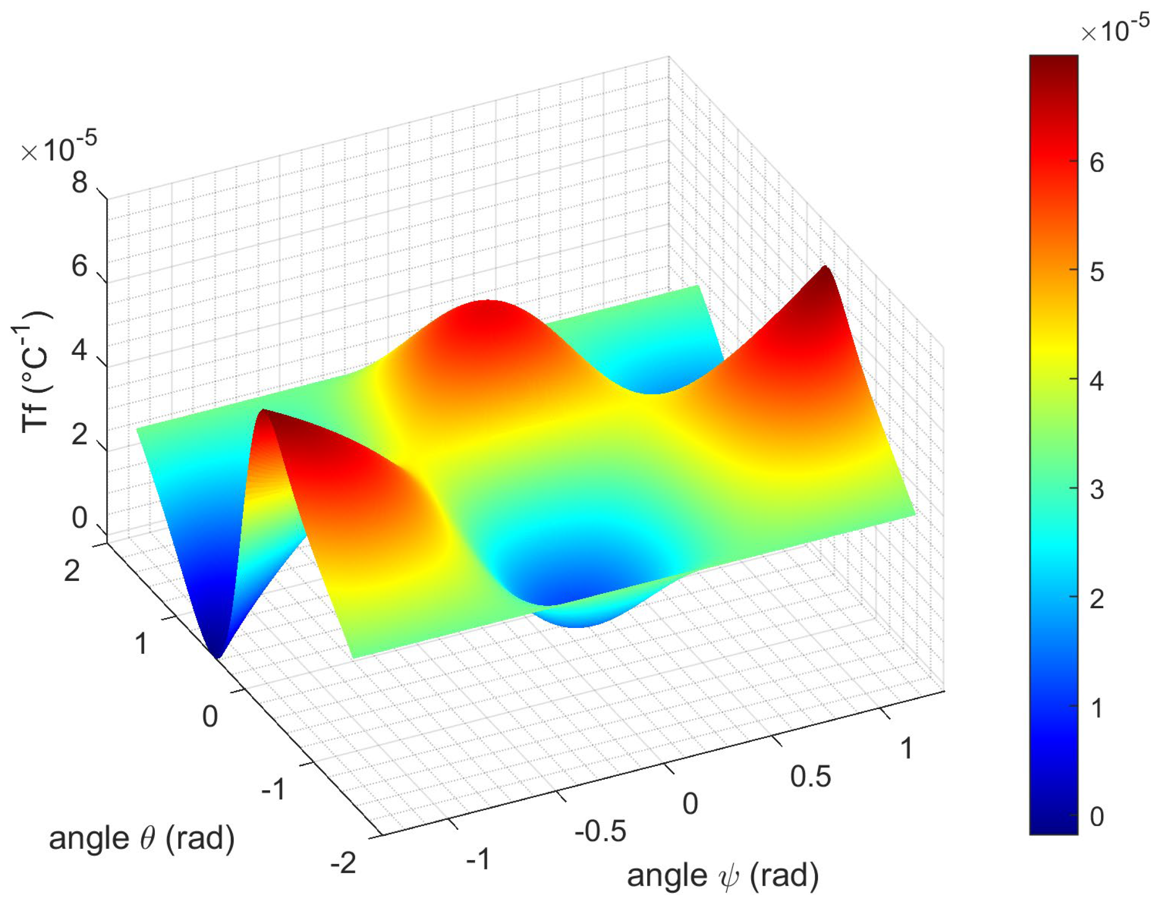
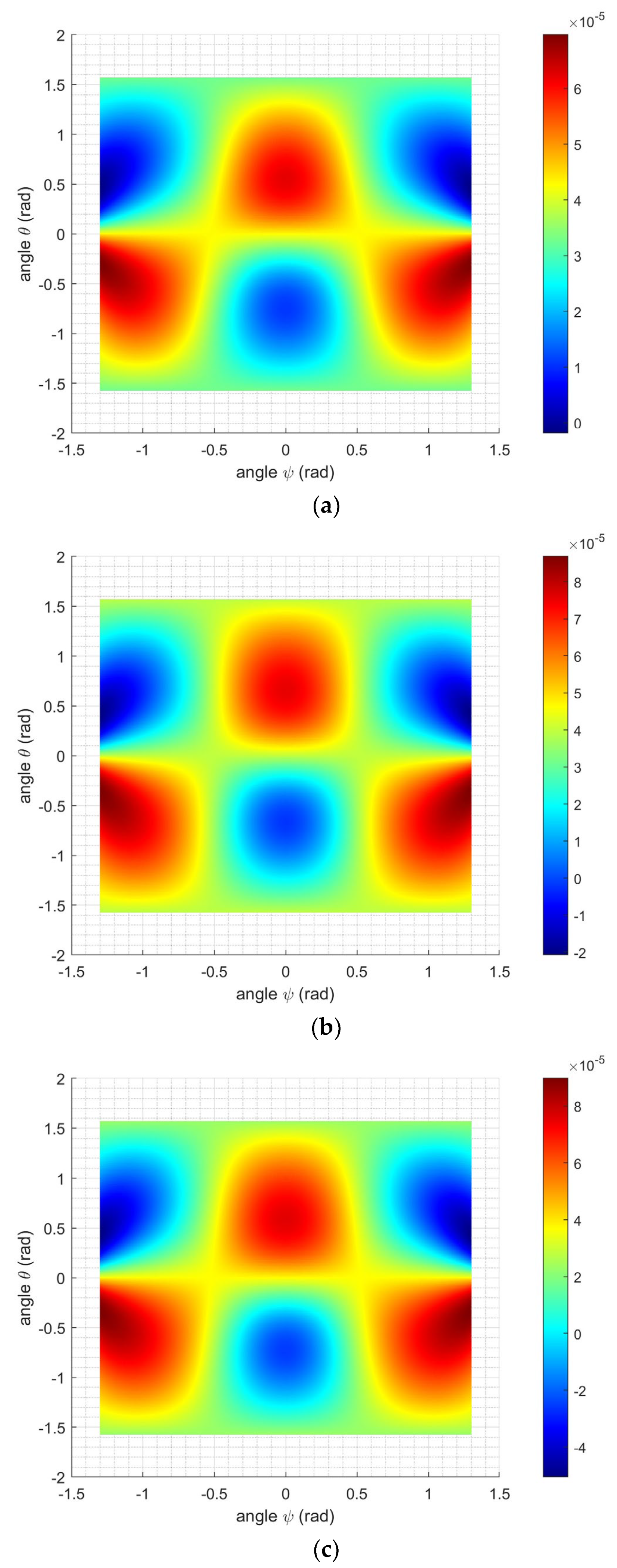
3.2.2. Doubly Rotated Y-Cut Plate

For doubly rotated Y-cut plates (Figure 1c,d), the thickness shear mode is now driven by the piezoelectric coefficient d 26 , and
x 6 = d 26 E 2
where the shear motion x 6 moves about Z″, while the electric field in the Y″ = Y′ direction is still located in the Y-Z plane, has just one component ( E 2 ), and can be written as E″ (0, E 2 ,0) in the new set of orthogonal axes (X″, Y″, Z″).
The resonant frequency is given by
f = 1 2 t C 66 ρ
where t is the thickness of the α-GeO2 plate, ρ is the density, and C 66 is the elastic coefficient, given by Equations (4) or (5), which governs the shear motion about Z″ for the doubly rotated Y-cuts. For both doubly rotated cuts, we have the following:
1 f d f d T = 1 t d t d T + 1 2 C 66 d C 66 d T 1 2 ρ d ρ d T
1 ρ d ρ d T = 2 α 11 + α 33
We find the following for (Yxlt) θ/ϕ:
1 t d t d T = α 22 = a 2 i a 2 j α i j = α 11 c o s 2 θ + α 33 s i n 2 θ
1 f d f d T = α 11 c o s 2 θ α 33 s i n 2 θ + 1 2 C 66 d C 66 d T + 1 2 2 α 11 + α 33
with
1 2 C 66 d C 66 d T = N D ,
N = ( s i n 2 ϕ c o s 2 θ s i n 2 θ ) C 11 T C 11 ( 1 ) ( 2 s i n 2 ϕ c o s 2 θ s i n 2 θ ) C 13 T C 13 ( 1 ) + s i n 2 θ c o s 2 ϕ + s i n 2 ϕ cos 2 θ C 14 T C 14 ( 1 ) + ( s i n 2 ϕ c o s 2 θ s i n 2 θ ) C 33 T C 33 ( 1 ) + s i n 2 ϕ c o s 2 2 θ + s i n 2 θ c o s 2 ϕ C 44 T C 44 ( 1 ) + ( c o s 2 θ c o s 2 ϕ ) C 66 T C 66 ( 1 )
and
D = 2 [ ( s i n 2 ϕ c o s 2 θ s i n 2 θ ) C 11 ( 2 s i n 2 ϕ c o s 2 θ s i n 2 θ ) C 13 + s i n 2 θ c o s 2 ϕ + s i n 2 ϕ cos 2 θ C 14 + ( s i n 2 ϕ c o s 2 θ s i n 2 θ ) C 33 + s i n 2 ϕ c o s 2 2 θ + s i n 2 θ c o s 2 ϕ C 44 + ( c o s 2 θ c o s 2 ϕ ) C 66 ]
Some temperature-compensated cuts for the doubly rotated Y-cuts exist, as can be seen in Figure 5 and Figure 6 for all temperatures in the range of [25 °C, 900 °C]. For temperatures T = 500 °C and 900 °C (Figure 6b and Figure 6c, respectively), the existence of compensated cuts for ϕ = 0 confirms the results for the (Yxl) θ plates (Figure 3a,b).
For (YXwl) ψ/θ, we have the following:
1 t d t d T = α 22 = a 2 i a 2 j α i j = α 11 c o s 2 θ + α 33 s i n 2 θ
1 f d f d T = α 11 c o s 2 θ α 33 s i n 2 θ + 1 2 C 66 d C 66 d T + 1 2 2 α 11 + α 33
with
1 2 C 66 d C 66 d T = 1 2 s i n θ c o s θ 2 c o s 3 ψ 6 c o s ψ s i n 2 ψ C 14 T C 14 1 + s i n 2 θ C 44 T C 44 1 + c o s 2 θ C 66 T C 66 1 s i n θ c o s θ 2 c o s 3 ψ 6 c o s ψ s i n 2 ψ C 14 + s i n 2 θ C 44 + c o s 2 θ C 66
Figure 7 and Figure 8a show no compensated cuts at an ambient temperature for ψ 90 ° . Such a rotation transforms the Y-plate to an X one, and the thickness shear mode disappears. For temperatures higher than ~460 °C, Figure 8b,c emphasize that temperature-compensated cuts exist, and for ψ = 0, we still find the results of the (YXl) θ plates, as illustrated in Figure 3a,b.
For a doubly rotated Y-cut plate (YXlt) θ/ϕ or (YXwl) ψ/θ, the required electric field to generate the thickness shear vibration mode is 0 , E 2 , 0 . We also have to check that parasitic vibration modes are not induced by the new direction of the applied electric field. Due to the equation of the reverse piezoelectric effect (in matrix notation with j = 1,…,6), x j = d 2 j E 2 , we have to evaluate d 21 , d 22 , d 23 , and d 24 to determine whether these rotations give rise to parasitic electromechanical coupling, as well as to quantify them.
By using the transformation law for the piezoelectric coefficient tensor, we find the following for a Y-cut plate (YXlt) θ/ϕ:
d 21 = d 211 = 2 c o s θ cos ϕ sin ϕ ( c o s θ d 14 2 s i n θ d 11 )
d 22 = d 222 = 0
d 23 = d 233 = 2 c o s θ cos ϕ sin ϕ 2 s i n θ d 11 c o s θ d 14 = d 21
d 24 = 2 d 223 = c o s θ sin ϕ ( 2 c o s θ d 11 s i n θ d 14 )
The others coupling coefficients, corresponding to the face shear and thickness shear, are as follows:
d 25 = 2 d 213 = sin 2 θ cos 2 ϕ d 11 c o s 2 θ cos 2 ϕ d 14
d 26 = 2 d 212 = 2 c o s 2 θ cos ϕ d 11 1 2 sin 2 θ cos ϕ d 14
For a (YXwl) ψ/θ plate,
d 21 = d 211 = c o s θ sin ψ ( s i n 2 ψ 3 c o s 2 ψ ) d 11
d 22 = d 222 = sin ψ c o s 3 θ d 11 ,
d 23 = d 233 = ( sin ψ s i n 2 θ c o s θ ) d 11
d 24 = 2 d 223 = 2 c o s 2 θ sinθ sin ψ ( s i n 2 ψ 5 c o s 2 ψ ) d 11
The other coupling coefficients corresponding to face shear and thickness shear are:
d 25 = 2 d 213 = 2 c o s θ sinθ cos ψ ( c o s 2 ψ 3 s i n 2 ψ ) d 11 c o s 2 θ d 14
d 26 = 2 d 212 = 2 c o s 2 θ cos ψ d 11 1 2 sin 2 θ cos ψ d 14
Finally, for doubly rotated Y-cut plates (YXlt) θ / ϕ and (YXwl) ψ / θ , parasitic electromechanical coupling modes appear as soon as the value of ϕ or ψ is non-zero. Nevertheless, if the values of these angles are low, there are only weak parasitic couplings.

3.3. Second-Order Resonance Frequency Temperature Coefficients for Rotated Y-Plates

By using the simplified Relation (5) and calculating the second-order temperature coefficient of the elastic constant C66 for different rotated cuts (Relations (7), (8), (10), and (11) for, respectively, (YXl) θ, (YXt) ϕ , (YXlt) θ/ϕ, and (YXwl) ψ/θ), we find T f ( 2 ) .
As shown in Figure 6b,d,f, the values of T f ( 2 ) in relation to θ and ϕ vary from the range [−1.10−7, +3.10−7] at 20 °C to [−2.10−7, +3.10−7] at 900 °C. In the entire temperature range, some rotated angles exist for which the T f ( 2 ) is canceled and the resonant frequency depends linearly on the temperature if the first-order temperature coefficient is non-zero.

4. Conclusions

This paper explores the high-temperature piezoelectric properties of α-GeO2 single crystals, demonstrating their superior thermal stability and applicability at elevated temperatures. Using the elastic constants Cij, measured between 25 °C and 900 °C, the study calculated the first-order, TCij(1), and second-order, TCij(2), temperature coefficients, which allowed for the determination of the frequency temperature coefficients Tf(1) and Tf(2) for thickness shear modes in simple and rotated Y-cut plates. These values are crucial in identifying cuts with minimal temperature-induced frequency drift or linear temperature dependence, enabling a stable performance over the entire temperature range.
In single rotations of Y-plates, temperatures above 450 °C are required for temperature-compensated cut angles; meanwhile, in the case of the double rotation of Y-plates, the existence of angle pairs (θ, ϕ) has been shown for temperature-compensated cuts over the entire range [25 °C, 900 °C]. However, to minimize parasitic couplings, small ϕ angles are recommended.
Unlike α-quartz, which is limited to temperatures below 573 °C due to a phase transition, α-GeO2 remains structurally stable up to 900 °C, making it a more suitable choice for high-temperature applications. Additionally, α-GeO2’s broader range of temperature-compensated Y-cut angles further minimizes frequency drift, outperforming α-quartz in applications where thermal stability is essential.
Finally, this research highlights α-GeO2 as a promising material for sensors and frequency control devices in extreme high-temperature environments due to its temperature-compensated cuts and superior thermal resilience.

Author Contributions

Conceptualization, P.P.; methodology, P.P.; software, P.P.; validation, P.P. and P.A.; formal analysis, P.P. and P.A.; investigation, P.P.; resources, P.P. and P.A.; writing—original draft preparation, P.P.; writing—review and editing, P.P. and P.A. All authors have read and agreed to the published version of the manuscript.

Funding

This research was funded by the French Ministry of Higher Education, Scientific Research and Innovation, the French National Center of Scientific Research (CNRS), and the French Research National Agency ANR [ANR-21-CE08-0017].

Data Availability Statement

The original contributions presented in the study are included in the article; further inquiries can be directed to the corresponding author.

Conflicts of Interest

The authors declare no conflicts of interest.

References

  1. Hamidon, M.V.; Skarda, V.; White, N.M.; Krispel, F.; Krempl, P.; Binhack, M. Buff. Fabrication of high temperature surface acoustic wave devices for sensor applications. Sens. Actuators A Phys. 2005, 403, 123–124. [Google Scholar]
  2. Daniau, W.; Salut, R.; Friedt, J.M.; Pena, A.; Menaert, B.; Armand, P.; Papet, P.; Penarier, A.; Nouvel, P. Experimental demonstration of Surface Acoustic Wave propagation on α-GeO2 for wireless, passive sensor design. In Proceedings of the 2023 IEEE International Frequency Control Symposium-European Frequency (EFTF/IFCS), Toyama, Japan, 15–19 May 2023; IEEE: New York, NY, USA, 2023; pp. 1–4. [Google Scholar] [CrossRef]
  3. Pena, A.; Felix, C.; Menaert, B.; Boulanger, B. Crystal growth, measurement and modeling of the optical activity of alpha-GeO2. Comparison with alpha-SiO2. arXiv 2025, arXiv:2501.12496. [Google Scholar] [CrossRef]
  4. Remark, T.; Segonds, P.; Pena, A.; Menaert, B.; Debray, J.; Pujol, M.C.; Boulanger, B. First Measurements of Nonlinear Second-Order Frequency Conversion Phase-Matching Conditions in the Uniaxial Crystal α-GeO2. In Laser Congress 2021 (ASSL, LAC); paper ATh2A.3; Optica Publishing Group: Washington, DC, USA, 2021; Available online: https://opg.optica.org/abstract.cfm?URI=ASSL-2021-ATh2A.3 (accessed on 18 April 2025).
  5. Remark, T.; Segonds, P.; Pena, A.; Menaert, B.; Debray, J.; Jegouso, D.; Pujol, M.C.; Boulanger, B. Linear and nonlinear optical properties of the piezoelectric crystal α-GeO2. Opt. Mater. Express 2021, 11, 3520–3527. [Google Scholar] [CrossRef]
  6. Armand, P.; Hermet, P.; Bantignies, J.L.; Haidoux, A.; Maurin, D.; Ménaert, B.; Pena, A.; Papet, P. Optical properties in the infrared range of the birefringent α-GeO2 single crystal. Mat. Res. Bull. 2020, 129, 110881. [Google Scholar] [CrossRef]
  7. Philippot, E.; Goiffon, A.; Ibanez, A.; Pintard, M. Structure Deformations and Existence of the α-β Transition in MXO4 Quartz-like Materials. J. Solid State Chem. 1994, 110, 356–362. [Google Scholar] [CrossRef]
  8. Philippot, E.; Palmier, D.; Pintard, M.; Goiffon, A. A General Survey of Quartz and Quartz-like Materials: Packing Distortions, Temperature, and Pressure Effects. J. Solid State Chem. 1996, 123, 1–13. [Google Scholar] [CrossRef]
  9. Balitsky, D.V.; Balitsky, V.S.; Pisarevley, Y.V.; Philippot, E.; Silvestrova, O.Y.; Pushcharovsky, D.Y. Growth of germanium dioxide single crystals with α-quartz structure and investigation of their crystal structure, optical, elastic, piezoelectric, dielectric and mechanical properties. Ann. Chim. Sci. Mat. 2001, 26, 183–192. [Google Scholar] [CrossRef]
  10. Krempl, P.W. Piezoelectricity in quartz analogs. J. Phys. IV Fr. 2005, 126, 95–100. [Google Scholar]
  11. Lignie, A.; Ménaert, B.; Armand, P.; Peña, A.; Debray, J.; Papet, P. Top Seeded Solution Growth and Structural Characterizations of α-Quartz-like Structure GeO2 Single Crystal. Cryst. Growth Des. 2013, 13, 4220–4225. [Google Scholar] [CrossRef]
  12. Armand, P.; Lignie, A.; Beaurain, M.; Papet, P. Flux-Grown Piezoelectric Materials: Application to α-Quartz Analogues. Crystals 2014, 4, 168–189. [Google Scholar] [CrossRef]
  13. Lignie, A.; Armand, P.; Papet, P. Growth of piezoelectric water-free GeO2 and SiO2-substituted GeO2 single-crystals. Inorg. Chem. 2011, 50, 9311–9317. [Google Scholar] [CrossRef] [PubMed]
  14. Lignie, A.; Granier, D.; Armand, P.; Haines, J.; Papet, P. Modulation of quartz-like GeO2 structure by Si substitution: An X-ray diffraction study of Ge1−xSixO2 (0 ≤ x < 0.2) flux-grown single crystals. J. Appl. Cryst. 2012, 45, 272–278. [Google Scholar] [CrossRef]
  15. Fraysse, G.; Lignie, A.; Hermet, P.; Armand, P.; Bourgogne, D.; Haines, J.; Ménaert, B.; Papet, P. Vibrational origin of the thermal stability in the highly distorted α-quartz-type material GeO2: An experimental and theoretical study. Inorg. Chem. 2013, 52, 7271–7279. [Google Scholar] [CrossRef]
  16. Papet, P.; Bah, M.; Haidoux, A.; Rufflé, B.; Menaert, B.; Revellez, A.P.; Debray, J.; Armand, P. High temperature piezoelectric properties of flux-grown α-GeO2 single crystal. J. Appl. Phys. 2019, 126, 144102. [Google Scholar] [CrossRef]
  17. 17.17.220.01; IEEE Standard on Piezoelectricity. IEEE: New York, NY, USA, 1987; Volume 176.
  18. Bechmann, R. Elastic and Piezoelectric Constants of Alpha-Quartz. Phys. Rev. 1958, 110, 1060. [Google Scholar] [CrossRef]
  19. Dziuba, R.F.; Weinschel, W.R. Temperature Compensated Crystal Oscillators. IEEE Trans. Instrum. Meas. 1963, 12, 67–77. [Google Scholar]
  20. Hibbert, D.A. Quartz Crystal Resonators and their Temperature Compensation. IEEE Trans. Ultrason. Ferroelectr. Freq. Control 1970, 17, 216–226. [Google Scholar]
  21. Vig, J.R.; Ballato, A. 4 Frequency Control Devices. Phys. Acoust. 1999, 24, 209–273. [Google Scholar] [CrossRef]
  22. Tiersten, H.F. Linear Piezoelectric Plate Vibrations; Springer Sciences + Business Media: New York, NY, USA, 1969. [Google Scholar] [CrossRef]
  23. Newnham, R.E. Properties of Materials: Anisotropy, Symmetry, Structure; OUP Oxford: Oxford, UK, 2005. [Google Scholar]
  24. Bechmann, R. Frequency-Temperature-Angle Characteristics of AT-Type Resonators Made of Natural and Synthetic Quartz. Proc. IRE 1956, 44, 1600–1607. [Google Scholar] [CrossRef]
  25. Jiang, X.; Kim, K.; Zhang, S.; Johnson, J.; Salazar, G. High-Temperature Piezoelectric Sensing. Sensors 2014, 14, 144–169. [Google Scholar] [CrossRef]
  26. Wu, J.; Gao, X.; Chen, J.; Wang, C.M.; Zhang, S.; Dong, S. Review of high temperature piezoelectric materials, devices, and applications. Acta Phys. Sin. 2018, 67, 207701-1–207701-30. [Google Scholar] [CrossRef]
  27. Lignie, A.; Zhou, W.; Armand, P.; Rufflé, B.; Mayet, R.; Debray, J.; Hermet, P.; Ménaert, B.; Thomas, P.; Papet, P. High-temperature Elastic moduli of Flux-grown alpha-GeO2 Single Crystal. ChemPhysChem 2014, 15, 118–125. [Google Scholar] [CrossRef]
Figure 1. Illustrations of two singly rotated α-GeO2 plates with the notations [16] (a) (YXl) θ and (b) (YXt) ϕ, and two doubly rotated α-GeO2 plates with the notations (c) (YXlt) θ/ϕ and (d) (YXwl) ψ/θ. The angles are positive for a counter-clockwise rotation and negative for a clockwise one (θ is positive and ϕ negative in (c), while θ is negative and ψ is positive in (d).
Crystals 15 00613 g001
Figure 2. Thermal evolution of the elastic stiffness constants: (a) C11, (b) C13, (c) C14, (d) C33, (e) C44, and (f) C66.
Crystals 15 00613 g002aCrystals 15 00613 g002b
Figure 3. (a) Three-dimensional plot of the first-order. Temperature coefficient of the resonant frequency T f ( 1 ) of the simply rotated (YXl) θ plate in relation to the rotation angle θ for temperatures in the range of [25 °C, 900 °C]; (b) plot of T f ( 1 ) in relation to the rotation angle θ at selected temperatures.
Crystals 15 00613 g003aCrystals 15 00613 g003b
Figure 4. Three-dimensional plot of the first-order resonant frequency temperature coefficient T f ( 1 ) of the singly rotated (Yxt) ϕ plate in relation to the rotation angle ϕ and the temperature (in the range of [25 °C, 900 °C]).
Crystals 15 00613 g004
Figure 5. Three-dimensional plot of the first-order resonant frequency temperature coefficient, T f ( 1 ) , of the doubly rotated (Yxlt) θ/ϕ plate at 20 °C in relation to the rotation angles θ and ϕ.
Crystals 15 00613 g005
Figure 6. Two-dimensional plot (projection on θ–ϕ plan) of the first- and second-order resonant frequency temperature coefficients, T f ( 1 ) and T f ( 2 ) , of the doubly rotated (YXlt) θ/ϕ plate in relation to the rotation angles θ and ϕ for different temperatures: (a) T f ( 1 ) at 20 °C; (b) T f ( 2 ) at 20 °C; (c) T f ( 1 ) at 500 °C; (d) T f ( 2 ) at 500 °C; (e) T f ( 1 ) at 900 °C; (f) T f ( 2 ) at 900 °C.
Crystals 15 00613 g006aCrystals 15 00613 g006b
Figure 7. Three-dimensional plot of the first-order resonant frequency temperature coefficient ( T f ( 1 ) ) of the doubly rotated (YXwl) ψ/θ plate at 20 °C in relation to the rotation angles ψ and θ.
Crystals 15 00613 g007
Figure 8. Two-dimensional plot (projection on θ–ψ plan) of the temperature derivative of the resonant frequency (Tf) of the doubly rotated (YXwl) ψ/θ plate in relation to the rotation angles θ and ψ at (a) T = 20 °C; (b) T = 500 °C; and (c) T = 900 °C.
Crystals 15 00613 g008
Table 1. Equations of the fitting curve (polynomial regression) of the elastic constants (in Gpa) versus the temperature T (in °C).
C 11 1.1905 * 10 9 * T 3 3.847 * 10 7 * T 2 + 2.4874 * 10 4 * T + 69.502
C 13 1.2177 * 10 9 * T 3 3.4702 * 10 6 * T 2 + 1.817 * 10 3 * T + 27.302
C 14 9.7854 * 10 7 * T 2 + 1.4603 * 10 3 * T 0.0647
C 33 1.8275 * 10 6 * T 2 9.7386 * 10 3 * T + 120.23
C 44 1.6394 * 10 9 * T 3 + 1.8384 * 10 6 * T 2 + 1.4454 * 10 3 * T + 38.735
C 66 9.1799 * 10 8 * T 2 + 1.8889 * 10 3 * T + 22.933
Table 2. Values of elastic stiffness (in Gpa) and first- and second-order temperature coefficients (in units of ppm°C−1) of α-GeO2 at T = 25 °C, 500 °C, and 900 °C.
Elastic Stiffness (Gpa)First-Order Temperature Coefficients of Cij (ppm°C−1)Second-Order Temperature Coefficients of Cij (ppm°C−2)
T = 25 °CT = 500 °CT = 900 °CT = 25 °CT = 500 °CT = 900 °CT = 25 °CT = 500 °CT = 900 °C
C 11 69.5169.3868.55+3.27−14.82−48.69−0.007−0.003−0.053
C 13 27.3427.5027.01+60.21−26.86−54.42−0.124−0.060−0.007
C 14 00.912.04+50,266.70+2680.22+1578.92−32.06+1.108+0.490
C 33 119.98114.90109.99−81.93−100.63−118.45−0.015−0.016−0.017
C 44 38.7739.7140.33+39.59+51.73+19.11+0.044−0.015−0.064
C 66 22.9823.8524.56+81.98+73.34+70.19−0.004−0.004−0.004
Table 3. Comparison of elastic constants (in Gpa) and first- and second-order temperature coefficient (in units of ppm°C−1) of α-SiO2 and α-GeO2.
Elastic Stiffness at 25 °C
(Gpa)
First-Order Temperature
Coefficients of Cij at 25 °C
(In Units of ppm°C−1)
Second-Order Temperature
Coefficients of Cij at 25 °C
(In Units of ppm°C−2)
α-SiO2 [17]α-GeO2α-SiO2 [17]α-GeO2α-SiO2 [17]α-GeO2
C 11 86.7469.51−48.50+3.27−0.107−0.007
C 13 11.9027.34−550.00+60.21−1.150−0.124
C 14 17.910.01+101.00+50,266.70−0.048−32.06
C 33 107.20119.98−160.00−81.93−0.275−0.015
C 44 57.9338.77−177.00+39.59−0.216+0.044
C 66 39.8922.98+178.00+81.980.118−0.004
Disclaimer/Publisher’s Note: The statements, opinions and data contained in all publications are solely those of the individual author(s) and contributor(s) and not of MDPI and/or the editor(s). MDPI and/or the editor(s) disclaim responsibility for any injury to people or property resulting from any ideas, methods, instructions or products referred to in the content.

