
Current Trends and Emerging Strategies in Friction Stir Spot Welding for Lightweight Structures: Innovations in Tool Design, Robotics, and Composite Reinforcement—A Review

 ,
,  ,
,  ,
,  , ,
, ,
Abstract
1. Introduction

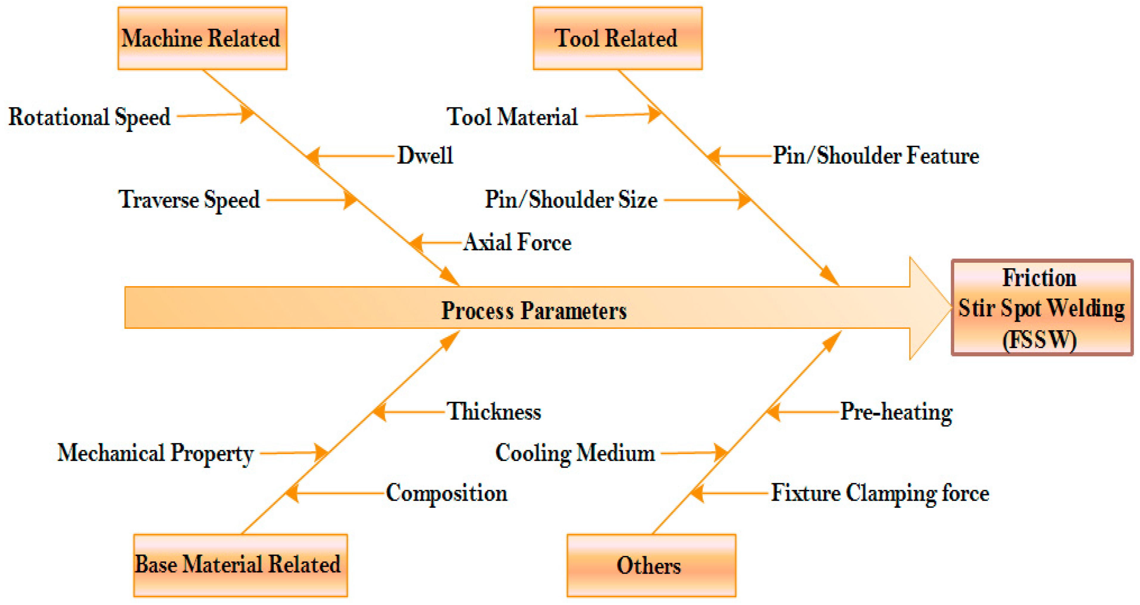
- Tool design: The shape, size, and material of the tool, particularly the pin, play a crucial role in the FSSW process. Different designs and materials can affect heat generation, material flow, and overall weld quality [17].
- Tool rotation speed: The speed at which the tool rotates plays a crucial role in both heat generation and material plasticization during the welding process. It is imperative to fine-tune this parameter to strike a balance, ensuring adequate heat for welding without inducing any material defects [18,19].
- Plunge depth: The extent to which the pin penetrates the workpieces directly influences the degree of material plasticization. Achieving an appropriate insertion depth is essential to produce a robust and defect-free weld [20].
- Welding force: The axial force applied during the welding process affects the contact between the tool and the workpieces, as well as the material flow and joint formation [21]. It needs to be controlled to ensure adequate plastic deformation without excessive force that may lead to defects.
- Material properties: The properties of the materials being joined, such as their composition, thickness, and mechanical properties, can influence the FSSW process. Different materials may require adjustments in process parameters to achieve satisfactory weld quality.
2. Progress in FSSW Process
2.1. FSSW of Similar Materials
2.2. FSSW of Dissimilar Materials
2.3. Double-Side FSSW Technique
2.4. Advancements in FSSW Tool Design
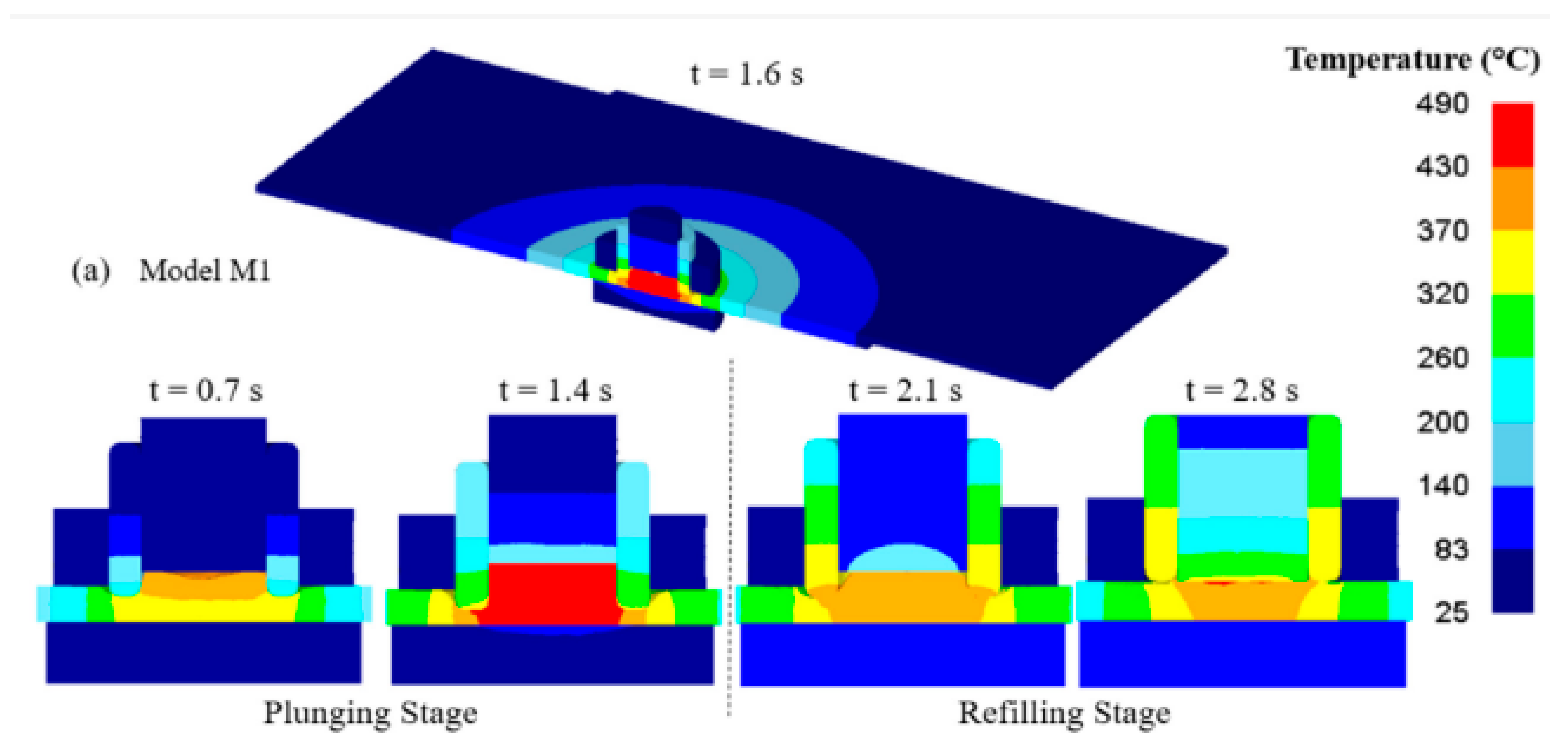
2.5. Numerical Simulation of FSSW
3. Emerging FSSW Techniques and Variations
3.1. Submerged Friction Welding
3.2. Friction Stir Spot Vibration Welding
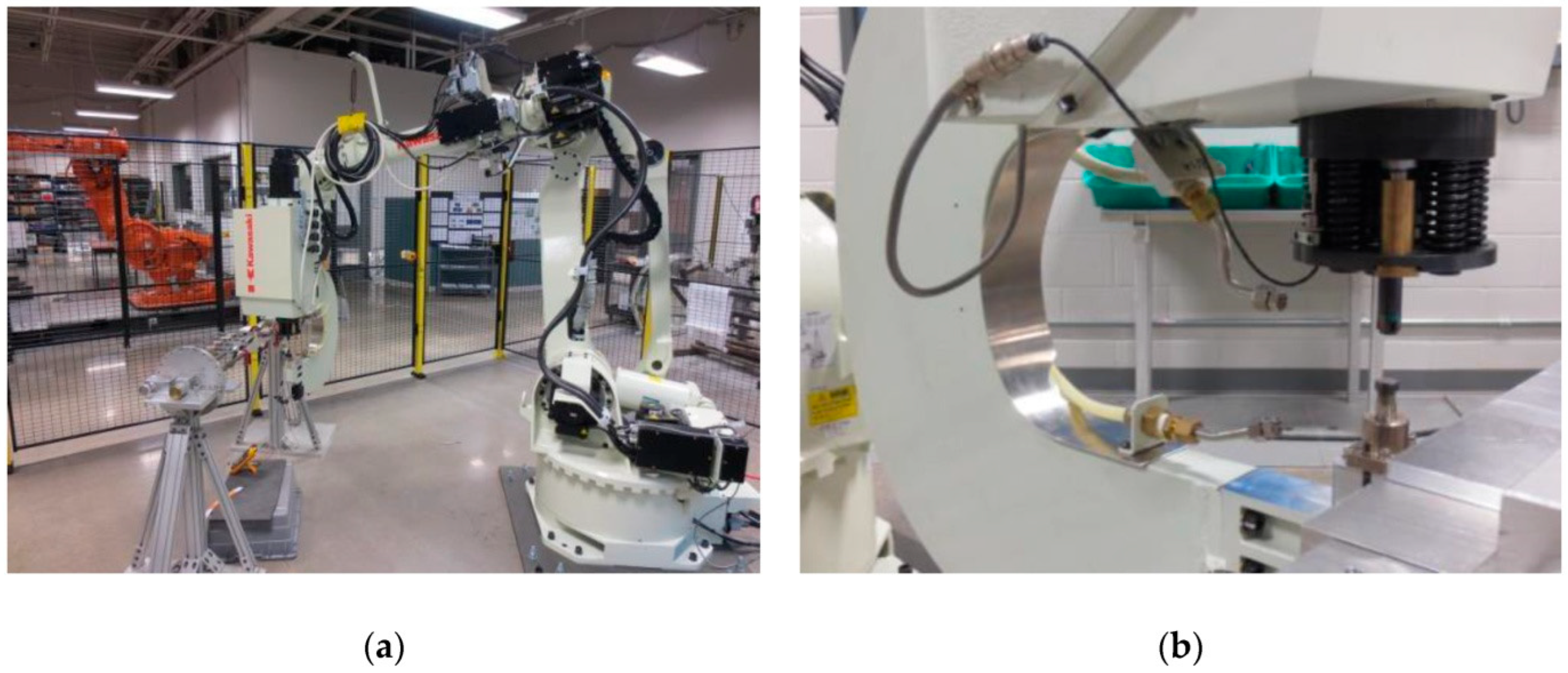
3.3. Robotic Assisted FSSW

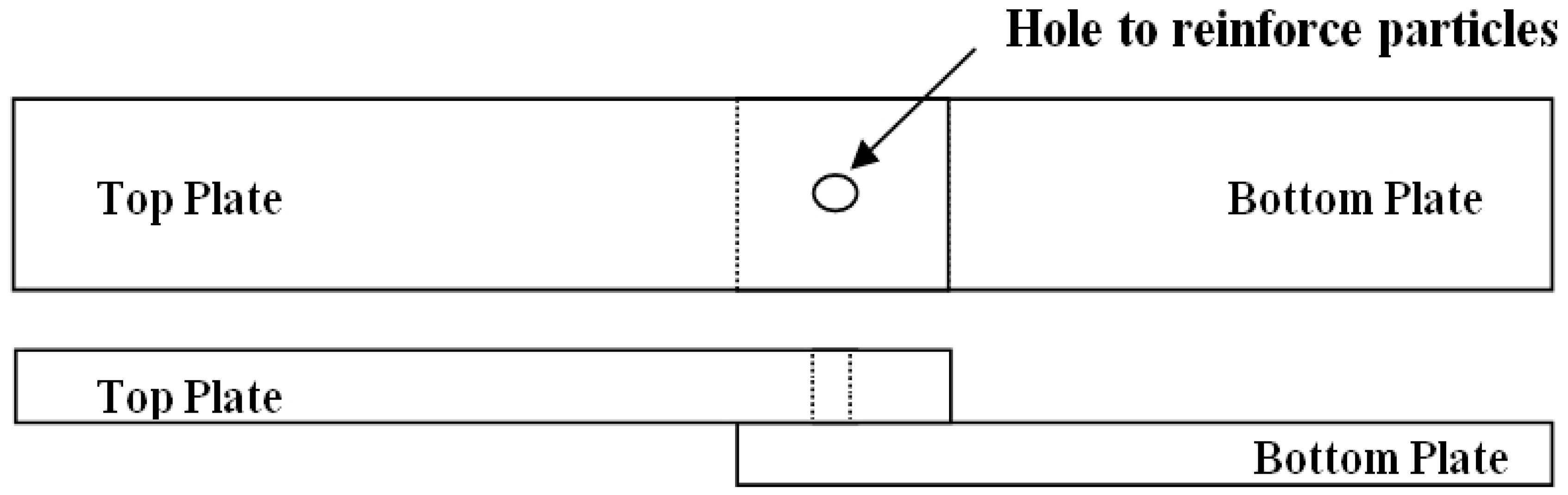
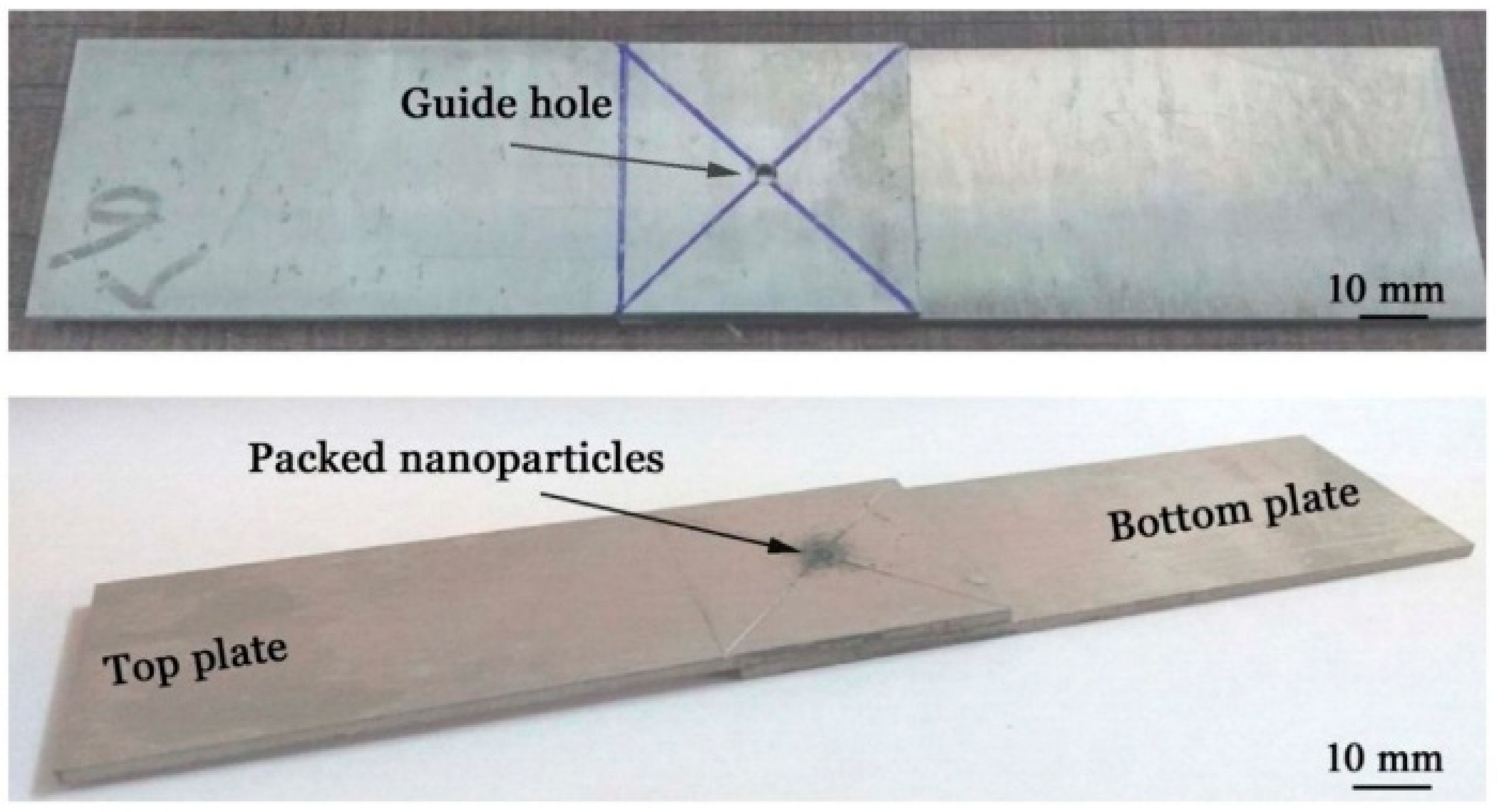
3.4. Reinforced Weld Joints
3.4.1. Effect of Nanoparticles on Microstructure Characteristics
3.4.2. Effect of Nanoparticles on Mechanical Properties
3.5. Mitigation of FSSW Defects
4. Future Outlook
5. Conclusions
- FSSW shows transformative potential in solid-state joining, offering high-quality welds efficiently and reliably across diverse industrial applications.
- Process parameters such as tool design, rotational speed, axial force, and dwell time are crucial for weld quality and performance. Innovations like friction stir spot vibration welding and robotic-assisted FSSW enhance material flow, reduce defects, and improve mechanical properties.
- Numerical simulations of FSSW have significantly improved understanding and optimization, accurately predicting heat transfer, material flow, and mechanical behavior to enhance joint quality and performance.
- Integrating nano/microparticles like carbon nanotubes, graphene, ceramic nanoparticles, and metallic reinforcements is a pivotal advancement, improving weld strength, hardness, wear resistance, and corrosion properties, though challenges in dispersion and particle agglomeration remain.
- FSSW effectively joins both similar and dissimilar materials, enabling new multi-material designs and applications. Robotic-assisted FSSW enhances precision, efficiency, and complex weld geometries, expanding its scope in high-performance industries.
- Future research is vital to address challenges, particularly in refining robotic programming and leveraging artificial intelligence for autonomous decision-making in welding processes. Further exploration of nano/microparticles in composite FSSW joints is a promising area for future investigation.
Author Contributions
Funding
Data Availability Statement
Acknowledgments
Conflicts of Interest
References
- Iwashita, T. Method and Apparatus for Joining. Google Patents EP1149656A3, 22 October 2003. [Google Scholar]
- Sathyaseelan, P.; Manickavasagam, V.M.; Ravichandran, P.; Prasad, D.V.S.S.S.V.; Ramana Murty Naidu, S.C.V.; Pradeep Kumar, S.; Ahmad Khan, A.; Karthik, R.; Kerga, G.A. Effect of Dwell Time on Fracture Load of Friction Stir Spot Welded Dissimilar Metal Joints. Adv. Mater. Sci. Eng. 2022, 2022, 2163507. [Google Scholar] [CrossRef]
- Sharma, C.; Tripathi, A.; Upadhyay, V.; Verma, V.; Sharma, K.S. Friction Stir Spot Welding-Process and Weld Properties: A Review. J. Inst. Eng. Ser. D 2021, 102, 549–565. [Google Scholar] [CrossRef]
- Tanmoy, D. Resistance Spot Welding: Principles and Its Applications. In Engineering Principles—Welding and Residual Stresses; IntechOpen: London, UK, 2022. [Google Scholar]
- Yang, X.W.; Fu, T.; Li, W.Y. Friction stir spot welding: A review on joint macro- and microstructure, property, and process modelling. Adv. Mater. Sci. Eng. 2014, 2014, 697170. [Google Scholar] [CrossRef]
- Gao, Z.; Feng, J.; Wang, Z.; Niu, J.; Sommitsch, C. Dislocation Density-Based Modeling of Dynamic Recrystallized Microstructure and Process in Friction Stir Spot Welding of AA6082. Metals 2019, 9, 672. [Google Scholar] [CrossRef]
- Benedyk, J.C. 3-Aluminum alloys for lightweight automotive structures. In Woodhead Publishing Series in Composites Science and Engineering, Materials, Design and Manufacturing for Lightweight Vehicles; Woodhead Publishing: Cambridge, UK, 2020; pp. 79–113. [Google Scholar] [CrossRef]
- Suresh, S.; Natarajan, E.; Vinayagamurthi, P.; Venkatesan, K.; Viswanathan, R.; Rajesh, S. Optimum Tool Traverse Speed Resulting Equiaxed Recrystallized Grains and High Mechanical Strength at Swept Friction Stir Spot Welded AA7075-T6 Lap Joints. In Materials, Design and Manufacturing for Sustainable Environment; Natarajan, E., Vinodh, S., Rajkumar, V., Eds.; Lecture Notes in Mechanical Engineering; Springer: Singapore, 2023. [Google Scholar] [CrossRef]
- Okamoto, K.; Hunt, F.; Hirano, S. Development of Friction Stir Welding Technique and Machine for Aluminum Sheet Metal Assembly-Friction Stir Welding of Aluminum for Automotive Applications (2); SAE 2005 Technical Paper 2005-01-1254; SAE International: Warrendale, PA, USA, 2005. [Google Scholar] [CrossRef]
- Badarinarayan, H.; Yang, Q.; Okamoto, K. Effect of weld orientation on static strength and failure mode of friction stir stitch welds in lap-shear specimens of aluminium 6022-T4 sheets. Fatigue Fract. Eng. Mater. Struct. 2011, 34, 908–920. [Google Scholar] [CrossRef]
- Kalagara, S.; Muci-Küchler, K.H.; Arbegast, W.J. Visualization of material flow in a refill friction stir spot welding process using marker materials. SAE Int. J. Mater. Manuf. 2010, 3, 628–651. [Google Scholar] [CrossRef]
- Pan, T.Y. Friction stir spot welding (FSSW)—A literature review. In SAE Technical Papers; SAE International: Warrendale, PA, USA, 2007. [Google Scholar]
- Kubit, A.; Trzepieciński, T.; Gadalińska, E.; Slota, J.; Bochnowski, W. Investigation into the Effect of RFSSW Parameters on Tensile Shear Fracture Load of 7075-T6 Alclad Aluminium Alloy Joints. Materials 2021, 14, 3397. [Google Scholar] [CrossRef]
- Walz, D.; Göbel, R.; Werz, M.; Weihe, S. Effect of Weld Length on Strength, Fatigue Behaviour and Microstructure of Intersecting Stitch-Friction Stir Welded AA 6016-T4 Sheets. Materials 2023, 16, 533. [Google Scholar] [CrossRef]
- Er, O.; Külekci, M.K.; Eşme, U.; Boğa, C. Multi Response Optimization of Friction Stir Spot Welding Process. Çukurova Üniversitesi Mühendislik Fakültesi Derg. 2021, 36, 421–432. [Google Scholar] [CrossRef]
- Kulekci, M.K.; Esme, U.; Er, O.; Kazancoglu, Y. Modeling and prediction of weld shear strength in friction stir spot welding using design of experiments and neural network. Materwiss Werksttech 2011, 42, 990–995. [Google Scholar] [CrossRef]
- Ramaiyan, S.; Santhanam, S.K.V.; Muthuguru, P. Effect of Scroll Pin Profile and Tool Rotational Speed on Mechanical Properties of Submerged Friction Stir Processed AZ31B Magnesium Alloy. Mater. Res. 2018, 21, e20170769. [Google Scholar] [CrossRef]
- Ahmed, M.M.Z.; El-Sayed Seleman, M.M.; Albaijan, I.; Abd El-Aty, A. Microstructure, Texture, and Mechanical Properties of Friction Stir Spot-Welded AA5052-H32: Influence of Tool Rotation Rate. Materials 2023, 16, 3423. [Google Scholar] [CrossRef] [PubMed]
- Sevvel, P.; Satheesh, C.; Jaiganesh, V. Influence of tool rotational speed on microstructural characteristics of dissimilar Mg alloys during friction stir welding. Trans. Can. Soc. Mech. Eng. 2019, 43, 132–141. [Google Scholar] [CrossRef]
- Kluz, R.; Kubit, A.; Wydrzyński, D. The Effect of Plunge Depth on the Strength Properties of Friction Welded Joints Using the RFSSW Method. Adv. Sci. Technol. Res. J. 2018, 12, 41–47. [Google Scholar] [CrossRef]
- Ramya, G.; Pounrajan, S.; Prasad, D.V.S.S.S.V.; Soni, S.; Ravichandran, P.; Kosanam, K.; Gopala Gupta, A.S.A.L.G.; Dinesh, P.M.; Kumar, L.; Shaik, B. Assessment of Rotational Speed and Plunge Rate on Lap Shear Strength of FSSW Joints of AA7075/Mild Steel. Adv. Mater. Sci. Eng. 2022, 2022, 6215249. [Google Scholar] [CrossRef]
- Yang, Q.; Mironov, S.; Sato, Y.S.; Okamoto, K. Material flow during friction stir spot welding. Mater. Sci. Eng. A 2010, 527, 4389–4398. [Google Scholar] [CrossRef]
- Gao, Z.; Niu, J.T.; Krumphals, F.; Enzinger, N.; Mitsche, S.; Sommitsch, C. FE modelling of microstructure evolution during friction stir spot welding in AA6082-T6. Weld. World 2013, 57, 895–902. [Google Scholar] [CrossRef]
- Yin, Y.H.; Sun, N.; North, T.H.; Hu, S.S. Hook formation and mechanical properties in AZ31 friction stir spot welds. J. Mater. Process. Technol. 2010, 210, 2062–2070. [Google Scholar] [CrossRef]
- Wang, D.A.; Lee, S.C. Microstructures and failure mechanisms of friction stir spot welds of aluminum 6061-T6 sheets. J. Mater. Process. Technol. 2007, 186, 291–297. [Google Scholar] [CrossRef]
- Uematsu, Y.; Tokaji, K.; Tozaki, Y.; Kurita, T.; Murata, S. Effect of re-filling probe hole on tensile failure and fatigue behaviour of friction stir spot welded joints in Al-Mg-Si alloy. Int. J. Fatigue 2008, 30, 1956–1966. [Google Scholar] [CrossRef]
- Suresh, S.; Venkatesan, K.; Natarajan, E.; Rajesh, S.; Lim, W.H. Evaluating weld properties of conventional and swept friction stir spot welded 6061-t6 aluminium alloy. Mater. Express 2019, 9, 851–860. [Google Scholar] [CrossRef]
- Doshia, S.; Ketan, V.; Mehta, N.D. Progress in the Welding of Al Alloy Thin Sheet and Future Prospectus for Automobile. J. Eng. Technol. Ind. Appl. 2024, 10, 42–49. [Google Scholar] [CrossRef]
- Tewary, A.; Upadhyay, C.; Yadav, R.K. Solid-State Welding of Magnesium Alloys. In Advances in Processing of Lightweight Metal Alloys and Composites; Materials Horizons: From Nature to Nanomaterials; Springer: Berlin/Heidelberg, Germany, 2023; pp. 123–145. [Google Scholar] [CrossRef]
- Gebreamlak, G.; Palani, S.; Sirhabizu, B.; Atnaw, S.M.; Gebremichae, E. Dissimilar friction stir welding process-a review. Adv. Mater. Process. Technol. 2022, 8, 3900–3922. [Google Scholar] [CrossRef]
- Hussein, S.A.; Hashim, A.J.; Khaleel, S.M.; Al-Obaidi, M.A.; Rashid, F.L. A Review of Recent Improvements, Developments, Influential Parameters and Challenges in the Friction Stir Welding Process. Int. J. Automot. Mech. Eng. 2024, 21, 11438–11452. [Google Scholar] [CrossRef]
- Ahmed, M.M.Z.; El-Sayed Seleman, M.M.; Sobih, A.M.E.-S.; Bakkar, A.; Albaijan, I.; Touileb, K.; Abd El-Aty, A. Friction Stir-Spot Welding of AA5052-H32 Alloy Sheets: Effects of Dwell Time on Mechanical Properties and Microstructural Evolution. Materials 2023, 16, 2818. [Google Scholar] [CrossRef]
- Bozzi, S.; Helbert-Etter, A.L.; Baudin, T.; Klosek, V.; Kerbiguet, J.G.; Criqui, B. Influence of FSSW parameters on fracture mechanisms of 5182 aluminium welds. J. Mater. Process. Technol. 2010, 210, 1429–1435. [Google Scholar] [CrossRef]
- Suresh, S.; Venkatesan, K.; Natarajan, E.; Rajesh, S. Influence of tool rotational speed on the properties of friction stir spot welded AA7075-T6/Al2O3 composite joint. Mater. Today Proc. 2020, 27, 62–67. [Google Scholar] [CrossRef]
- Suresh, S.; Natarajan, E.; Shanmugam, R.; Venkatesan, K.; Saravanakumar, N.; AntoDilip, A. Strategized friction stir welded AA6061-T6/SiC composite lap joint suitable for sheet metal applications. J. Mater. Res. Technol. 2022, 21, 30–39. [Google Scholar] [CrossRef]
- Suresh, S.; Venkatesan, K.; Natarajan, E. Influence of SiC nanoparticle reinforcement on FSS welded 6061-T6 aluminum alloy. J. Nanomater. 2018, 2018, 7031867. [Google Scholar] [CrossRef]
- Li, S.; Yang, X.; Hou, J.; Du, W. A review on thermal conductivity of magnesium and its alloys. J. Magnes. Alloys 2020, 8, 78–90. [Google Scholar] [CrossRef]
- Rana, P.K.; Ganesh Narayanan, R.; Kailas, S.V. Influence of Tool Plunge Depth During Friction Stir Spot Welding of AA5052-H32/HDPE/AA5052-H32 Sandwich Sheets. In Strengthening and Joining by Plastic Deformation; Dixit, U.S., Narayanan, R.G., Eds.; Lecture Notes on Multidisciplinary Industrial Engineering, Influence; Springer: Singapore, 2019; pp. 95–121. [Google Scholar]
- Jagadeesha, C.B. Analysis and design of friction stir welding tool. J. Mech. Behav. Mater. 2017, 25, 179–182. [Google Scholar] [CrossRef]
- Zhou, L.; Zhang, R.; Li, G.; Zhou, W.; Huang, Y.; Song, X. Effect of pin profile on microstructure and mechanical properties of friction stir spot welded Al-Cu dissimilar metals. J. Manuf. Process. 2018, 36, 1–9. [Google Scholar] [CrossRef]
- Li, H.; Gao, J.; Li, Q.; Galloway, A.; Toumois, A. Effect of friction stir welding tool design on welding thermal efficiency. Sci. Technol. Weld. Join. 2019, 24, 156–162. [Google Scholar] [CrossRef]
- Maji, P.; Karmakar, R.; Kanti Nath, R.; Paul, P. An overview on friction stir welding/processing tools. Mater. Today Proc. 2022, 58, 57–64. [Google Scholar] [CrossRef]
- Joshi, S.K.; Gandhi, J.D. Influence of Tool Shoulder Geometry on Friction Stir Welding: A Literature Review. In Proceedings of the 2nd International Conference on Multidisciplinary Research & Practice, Gujarat, India, 24 December 2015; pp. 261–264. [Google Scholar]
- Nagarajan, B.M.; Manoharan, M. Enhancement of joint strength of dissimilar aluminum/polymer hybrid joints by friction stir spot welding by surface textures. J. Adhes. Sci. Technol. 2023, 38, 1284–1311. [Google Scholar] [CrossRef]
- Rodrigues, D.; Loureiro, A.; Leitao, C.; Leal, R.; Chaparro, B.; Vilaça, P. Influence of friction stir welding parameters on the microstructural and mechanical properties of AA 6016-T4 thin welds. Mater. Des. 2009, 30, 1913–1921. [Google Scholar] [CrossRef]
- Gerlich, A.; Su, P.; Yamamoto, M.; North, T.H. Effect of welding parameters on the strain rate and microstructure of friction stir spot welded 2024 aluminum alloy. J. Mater. Sci. 2007, 42, 5589–5601. [Google Scholar] [CrossRef]
- Baudin, T.; Bozzi, S.; Brisset, F.; Azzeddine, H. Local Microstructure and Texture Development during Friction Stir Spot of 5182 Aluminum Alloy. Crystals 2023, 13, 540. [Google Scholar] [CrossRef]
- Badwelan, A.; Al-Samhan, A.M.; Anwar, S.; Hidri, L. Novel Technique for Enhancing the Strength of Friction Stir Spot Welds through Dynamic Welding Parameters. Metals 2021, 11, 280. [Google Scholar] [CrossRef]
- Ahmed, M.M.; El-Sayed Seleman, M.M.; Ahmed, E.; Reyad, H.A.; Touileb, K.; Albaijan, I. Friction Stir Spot Welding of Different Thickness Sheets of Aluminum Alloy AA6082-T6. Materials 2022, 15, 2971. [Google Scholar] [CrossRef]
- Zhang, Z.; Yang, X.; Zhang, J.; Zhou, G.; Xu, X.; Zou, B. Effect of welding parameters on microstructure and mechanical properties of friction stir spot welded 5052 aluminum alloy. Mater. Des. 2011, 32, 4461–4470. [Google Scholar] [CrossRef]
- Uğurlu, M.; Çakan, A. The Effect of Tool Rotation Speed on Mechanical Properties of Friction Stir Spot Welded (FSSW) AA7075-T6 Aluminium Alloy Sheets. Eur. Mech. Sci. 2019, 3, 97–101. [Google Scholar] [CrossRef]
- Anton Savio Lewise, K.; Edwin Raja Dhas, J.; Pandiyarajan, R. Corrosion Behavior of FSSWed AA2024 and AA7075 Dissimilar Aluminum-Alloy. In Recent Advances in Materials Technologies; Rajkumar, K., Jayamani, E., Ramkumar, P., Eds.; Springer Nature: Singapore, 2023; pp. 225–232. [Google Scholar]
- Savguira, Y.; Liu, W.; Miklas, D.; North, T.H.; Thorpe, S.J. Mass-Loss Testing in Magnesium AZ31 Friction Stir Spot Welds. Corrosion 2014, 70, 858. [Google Scholar] [CrossRef] [PubMed]
- Yuri Savguira, T.H.N.; Thorpe, S.J. Effect of grain orientation on the corrosion resistance of FSSW joints made in AZ31B. Corros. Eng. Sci. Technol. 2017, 52, 195–200. [Google Scholar] [CrossRef]
- Ojo, O.O.; Taban, E.; Kaluc, E. Friction stir spot welding of aluminum alloys: A recent review. Mater. Test. 2015, 57, 609–627. [Google Scholar] [CrossRef]
- Chen, K.; Liu, X.; Ni, J. Effects of process parameters on friction stir spot welding of aluminum alloy to advanced high-strength steel. J. Manuf. Sci. Eng. Trans. ASME 2017, 139, 81016. [Google Scholar] [CrossRef]
- Sar, M.H.; Salim, R.K.; Zahra, H.K.A.; Abdullah, I.T.; Barrak, O.S.; Elechi, S.B.; Chatti, S. Friction stir spot welding (FSSW) of dissimilar aluminum alloys (AA5052 with AA6061). AIP Conf. Proc. 2024, 3105, 020025. [Google Scholar]
- Neeru Singh, S.; Satsangi, P.S. A review on friction stir spot welding of similar and dissimilar materials. In Advances in Engineering Design; Lecture Notes in Mechanical Engineering; Springer: Berlin/Heidelberg, Germany, 2021; pp. 531–541. [Google Scholar]
- Badarinarayan, H.; Yang, Q.; Zhu, S. Effect of tool geometry on static strength of friction stir spot-welded aluminum alloy. Int. J. Mach. Tools Manuf. 2009, 49, 142–148. [Google Scholar] [CrossRef]
- Kumar, S.; Maurya, M.; Sharma, T.; Kumar, A.; Jambhale, S.; Shankar, R.; Mishra, D.; Nitu. Optimization and ANFIS-based modeling of two step FSSW process parameters on tensile strength for triple-sheet joining of aluminum alloy. Proc. Inst. Mech. Eng. Part C J. Mech. Eng. Sci. 2024, 238, 2815–2830. [Google Scholar] [CrossRef]
- Shen, Z.; Yang, X.; Zhang, Z.; Cui, L.; Yin, Y. Mechanical properties and failure mechanisms of friction stir spot welds of AA 6061-T4 sheets. Mater. Des. 2013, 49, 181–191. [Google Scholar] [CrossRef]
- Tier, M.D.; dos Santos, J.F.; Olea, C.W.; Rosendo, T.; Mazzaferro, C.P.; Mazzafero, J.A.E.; Strohaecker, T.R.; da Silva, A.A.M.; Isakovic, J.-T. The Influence of Weld Microstructure on Mechanical Properties of Alclad AA2024-T3 Friction Spot Welded; SAE Technical Paper 2008-01-2287; SAE International: Warrendale, PA, USA, 2008. [Google Scholar] [CrossRef]
- Suresh, S.; Velmurugan, D.; Balaji, J.; Sudhagar, S.; Elayaraja, R. Advanced Joining Methods for Lightweight Materials in Sustainable Manufacturing. In Futuristic Technology for Sustainable Manufacturing; Singh, S., Gupta, S., Jagtap, S., Eds.; IGI Global Scientific Publishing: Hershey, PA, USA, 2024; pp. 17–36. [Google Scholar] [CrossRef]
- Tier, M.; Rosendo, T.; Dos Santos, J.; Huber, N.; Mazzaferro, J.; Mazzaferro, C.; Strohaecker, T. The influence of refill FSSW parameters on the microstructure and shear strength of 5042 aluminium welds. J. Mater. Process. Technol. 2013, 213, 997–1005. [Google Scholar] [CrossRef]
- Nathan, S.R.; Rajendran, C.; Sonar, T.; Ivanov, M.; Balasubramanian, K.; Anandan, H.B.R.; Sankaravadivelu, S.; Varaprasad, C. Optimization of CNC-FSSW parameters for dissimilar spot welding of AA6061 aluminium alloy and mild steel using Taguchi based desirability function approach. Int. J. Interact. Des. Manuf. 2024, 19, 337–346. [Google Scholar] [CrossRef]
- Shen, J.; Min, D.; Wang, D. Effects of heating process on the microstructures and tensile properties of friction stir spot welded AZ31 magnesium alloy plates. Mater. Des. 2011, 32, 5033–5037. [Google Scholar] [CrossRef]
- Liu, Z.; Fan, Z.; Liu, L.; Miao, S.; Lin, Z.; Wang, C.; Zhao, Y.; Xin, R.; Dong, C. Refill friction stir spot welding of AZ31 magnesium alloy sheets: Metallurgical features, microstructure, texture and mechanical properties. J. Mater. Res. Technol. 2023, 23, 3337–3350. [Google Scholar] [CrossRef]
- Ekinci, O.; Balalan, Z. Influence of tool pin shape and rotation speed for friction stir spot welding of AZ91 magnesium alloy sheets. Mater. Test. 2023, 65, 1281–1291. [Google Scholar] [CrossRef]
- Fu, B.; Damer, N.; Kirchbuchner, F.; Kuijper, A. Generalization of Fitness Exercise Recognition from Doppler Measurements by Domain-Adaption and Few-Shot Learning. In Pattern Recognition. ICPR International Workshops and Challenges; Del Bimbo, A., Cucchiara, R., Sclaroff, S., Farinella, G.M., Mei, T., Bertini, M., Escalante, H.J., Vezzani, R., Eds.; Lecture Notes in Computer Science (including subseries Lecture Notes in Artificial Intelligence and Lecture Notes in Bioinformatics); Springer International Publishing: Cham, Switzerland, 2021; pp. 203–218. [Google Scholar]
- Fu, B.; Shen, J.; Suhuddin, U.F.H.R.; Chen, T.; Santos, J.F.D.; Klusemann, B.; Rethmeier, M. Improved mechanical properties of cast Mg alloy welds via texture weakening by differential rotation refill friction stir spot welding. Scr. Mater. 2021, 203, 114113. [Google Scholar] [CrossRef]
- Sanusi, K.O.; Akinlabi, E.T.; Muzenda, E.; Akinlabi, S.A. Enhancement of Corrosion Resistance Behaviour of Frictional Stir Spot Welding of Copper. Mater. Today Proc. 2015, 2, 1157–1165. [Google Scholar] [CrossRef]
- Takashi, M.; Atsushi, K.; Kohei, O.; Akira, M.; Masaru, S. Friction stir spot welding of cold-rolled low carbon steel plates using TiC0.5N0.5–Xwt%W (X=70, 72, 75) cermet tool specimens. J. Mater. Res. Technol. 2024, 30, 7095–7103. [Google Scholar] [CrossRef]
- Lambiase, F.; Paoletti, A.; Di Ilio, A. Mechanical behaviour of friction stir spot welds of polycarbonate sheets. Int. J. Adv. Manuf. Technol. 2015, 80, 301–314. [Google Scholar] [CrossRef]
- Lambiase, F.; Paoletti, A.; Di Ilio, A. Effect of tool geometry on mechanical behavior of friction stir spot welds of polycarbonate sheets. Int. J. Adv. Manuf. Technol. 2017, 88, 3005–3016. [Google Scholar] [CrossRef]
- Lambiase, F.; Paoletti, A.; Di Ilio, A. Friction spot stir welding of polymers: Control of plunging force. Int. J. Adv. Manuf. Technol. 2017, 90, 2827–2837. [Google Scholar] [CrossRef]
- Suresh, S.; Velmurugan, D.; Balaji, J.; Natarajan, E.; Suresh, P.; Rajesh, S. Influences of Nanoparticles in Friction Stir Welding Processes. In Sustainable Utilization of Nanoparticles and Nanofluids in Engineering Applications; Boopathi, S., Davim, J., Eds.; IGI Global Scientific Publishing: Hershey, PA, USA, 2023; pp. 32–55. [Google Scholar] [CrossRef]
- Feizollahi, V.; Gerami, Y.; Saki, A.; Adelzadeh, B.; Zamani, M.; Hasab, M.G.; Moghadam, A.H. The effect of pin diameter, tool penetration depth and plate arrangement on mechanical and metallurgical properties of 6061-T6 and 5052-T32 aluminum dissimilar joints in friction stir spot welding (FSSW). Heliyon 2024, 10, e36962. [Google Scholar] [CrossRef] [PubMed]
- Suresh, S.; Premnath, P.; Balaji, C.; Kavinkumar, P.; Bharathraj, B. Friction stir welding: A comprehensive review of non-metallic particle reinforcement in joints. J. Mater. Eng. 2024, 2, 207–219. [Google Scholar] [CrossRef]
- Feizollahi, V.; Yousefi, M.; Elahifar, A.; Pourmirza, B.; Hasab, M.G.; Moghadam, A.H. Effect of shoulder diameter, tool rotation speed, and arrangement of plates on mechanical and metallurgical properties of dissimilar aluminum 2024-T3 and 7075-T6 friction stir spot welding (FSSW). Eng. Fail. Anal. 2024, 163, 108548. [Google Scholar] [CrossRef]
- Gurel Çam, V.J.; Heidarzadeh, A. Advances in FSW and FSSW of dissimilar Al-alloy plates. J. Adhes. Sci. Technol. 2023, 37, 162–194. [Google Scholar] [CrossRef]
- Manickam, S.; Rajendran, C.; Ragu Nathan, S.; Sivamaran, V.; Balasubramanian, V. Assessment of the influence of FSSW parameters on shear strength of dissimilar materials joint (AA6061/AZ31B). Int. J. Light. Mater. Manuf. 2023, 6, 33–45. [Google Scholar] [CrossRef]
- Alaeibehmand, S.; Mirsalehi, S.E.; Ranjbarnodeh, E. Pinless FSSW of DP600/Zn/AA6061 dissimilar joints. J. Mater. Res. Technol. 2021, 15, 996–1006. [Google Scholar] [CrossRef]
- Li, M.; Zhang, C.; Wang, D.; Zhou, L.; Wellmann, D.; Tian, Y. Friction stir spot welding of aluminum and copper: A review. Materials 2020, 13, 156. [Google Scholar] [CrossRef]
- Tozaki, Y.; Uematsu, Y.; Tokaji, K. Effect of processing parameters on static strength of dissimilar friction stir spot welds between different aluminium alloys. Fatigue Fract. Eng. Mater. Struct. 2007, 30, 143–148. [Google Scholar] [CrossRef]
- Mubiayi, M.P.; Akinlabi, E.T.; Makhatha, M.E. Microstructure and electrical resistivity properties of copper and aluminium friction stir spot welds. In Proceedings of the 2017 8th International Conference on Mechanical and Intelligent Manufacturing Technologies, ICMIMT 2017, Cape Town, South Africa, 3–6 February 2017; pp. 42–47. [Google Scholar]
- Li, G.; Zhou, L.; Zhou, W.; Song, X.; Huang, Y. Influence of dwell time on microstructure evolution and mechanical properties of dissimilar friction stir spot welded aluminum-copper metals. J. Mater. Res. Technol. 2019, 8, 2613–2624. [Google Scholar] [CrossRef]
- Prasomthong, S.; Sangsiri, P.; Kimapong, K. Friction Stir Spot Welding of AA5052 Aluminum Alloy and C11000 Copper Lap Joint. Int. J. Adv. Cult. Technol. 2015, 3, 145–152. [Google Scholar] [CrossRef]
- Chen, K.; Liu, X.; Ni, J. Keyhole refilled friction stir spot welding of aluminum alloy to advanced high strength steel. J. Mater. Process. Technol. 2017, 249, 452–462. [Google Scholar] [CrossRef]
- Alaeibehmand, S.; Ranjbarnodeh, E.; Mirsalehi, S.E. Joining mechanism in pinless FSSW of aluminum-steel with or without Zn and brass interlayers. Mater. Charact. 2021, 180, 111400. [Google Scholar] [CrossRef]
- Jedrasiak, P.; Shercliff, H.R.; Reilly, A.; Mcshane, G.J.; Chen, Y.C.; Wang, L.; Robson, J.; Prangnell, P. Thermal Modeling of Al-Al and Al-Steel Friction Stir Spot Welding. J. Mater. Eng. Perform. 2016, 25, 4089–4098. [Google Scholar] [CrossRef]
- Sato, Y.S.; Shiota, A.; Kokawa, H.; Okamoto, K.; Yang, Q.; Kim, C. Effect of interfacial microstructure on lap shear strength of friction stir spot weld of aluminium alloy to magnesium alloy. Sci. Technol. Weld. Join. 2010, 15, 319–324. [Google Scholar] [CrossRef]
- Suhuddin, U.F.H.; Fischer, V.; Dos Santos, J.F. The thermal cycle during the dissimilar friction spot welding of aluminum and magnesium alloy. Scr. Mater. 2013, 68, 87–90. [Google Scholar] [CrossRef]
- Fu, B.; Shen, J.; Suhuddin, U.F.H.R.; Pereira, A.A.C.; Maawad, E.; Santos, J.F.D.; Klusemann, B.; Rethmeier, M. Revealing joining mechanism in refill friction stir spot welding of AZ31 magnesium alloy to galvanized DP600 steel. Mater. Des. 2021, 209, 109997. [Google Scholar] [CrossRef]
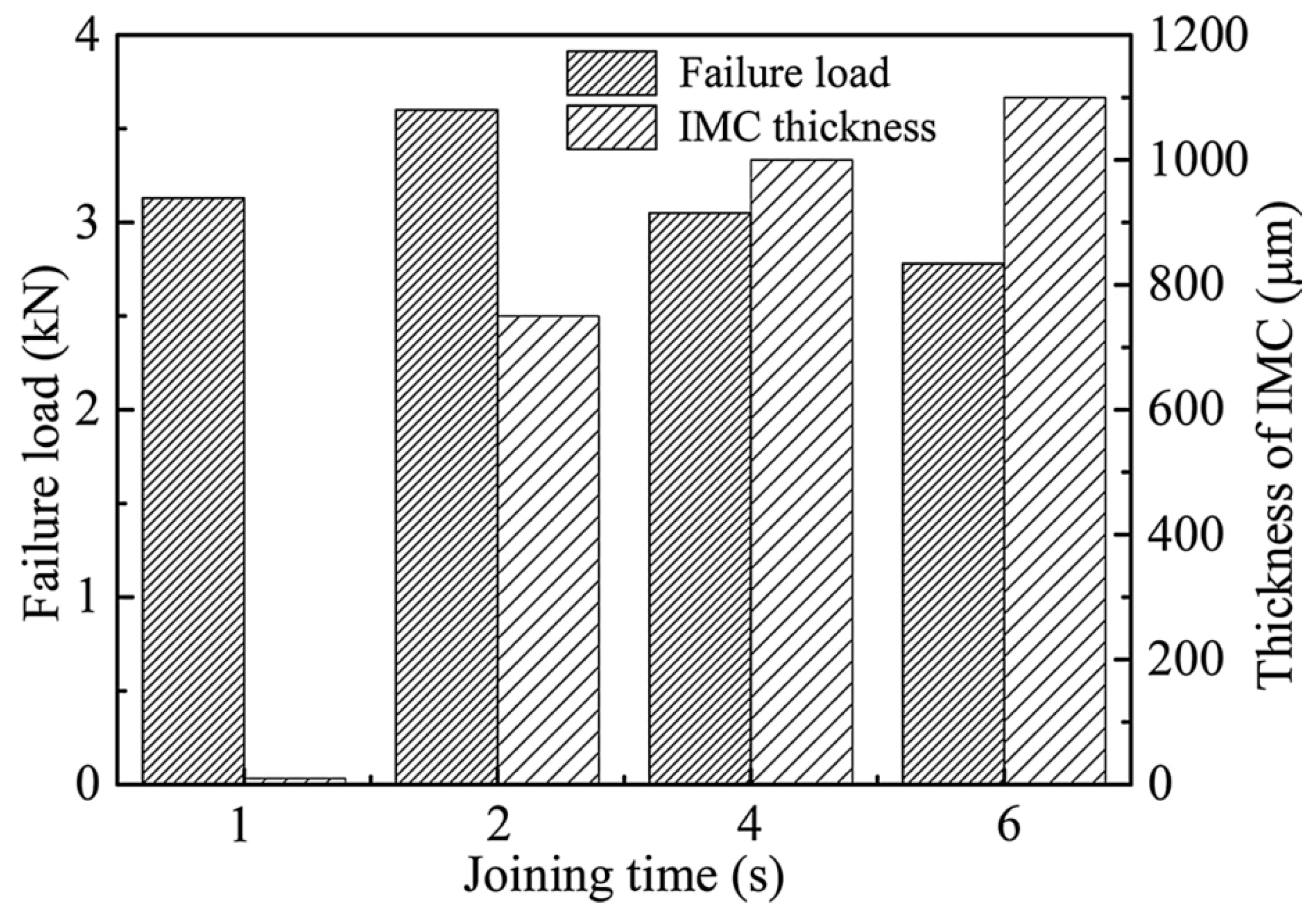
- Dong, Z.; Song, Q.; Ai, X.; Lv, Z. Effect of joining time on intermetallic compound thickness and mechanical properties of refill friction stir spot welded dissimilar Al/Mg alloys. J. Manuf. Process. 2019, 42, 106–112. [Google Scholar] [CrossRef]
- Chu, Q.; Li, W.Y.; Hou, H.L.; Yang, X.W.; Vairis, A.; Wang, C.; Wang, W.B. On the double-side probeless friction stir spot welding of AA2198 Al-Li alloy. J. Mater. Sci. Technol. 2019, 35, 784–789. [Google Scholar] [CrossRef]
- Wang, X.; Morisada, Y.; Ushioda, K.; Fujii, H. Double-sided friction stir spot welding of ultra-high strength C-Mn-Si martensitic steel by adjustable probes. J. Mater. Process. Technol. 2022, 300, 117422. [Google Scholar] [CrossRef]
- Lyu, X.; Li, M.; Li, X.; Chen, J. Double-sided friction stir spot welding of steel and aluminum alloy sheets. Int. J. Adv. Manuf. Technol. 2018, 96, 2875–2884. [Google Scholar] [CrossRef]
- Wang, X.; Morisada, Y.; Fujii, H. Flat friction stir spot welding of AZ31B magnesium alloy using double side adjustable tools: Microstructure and mechanical properties. Sci. Technol. Weld. Join. 2020, 25, 644–652. [Google Scholar] [CrossRef]
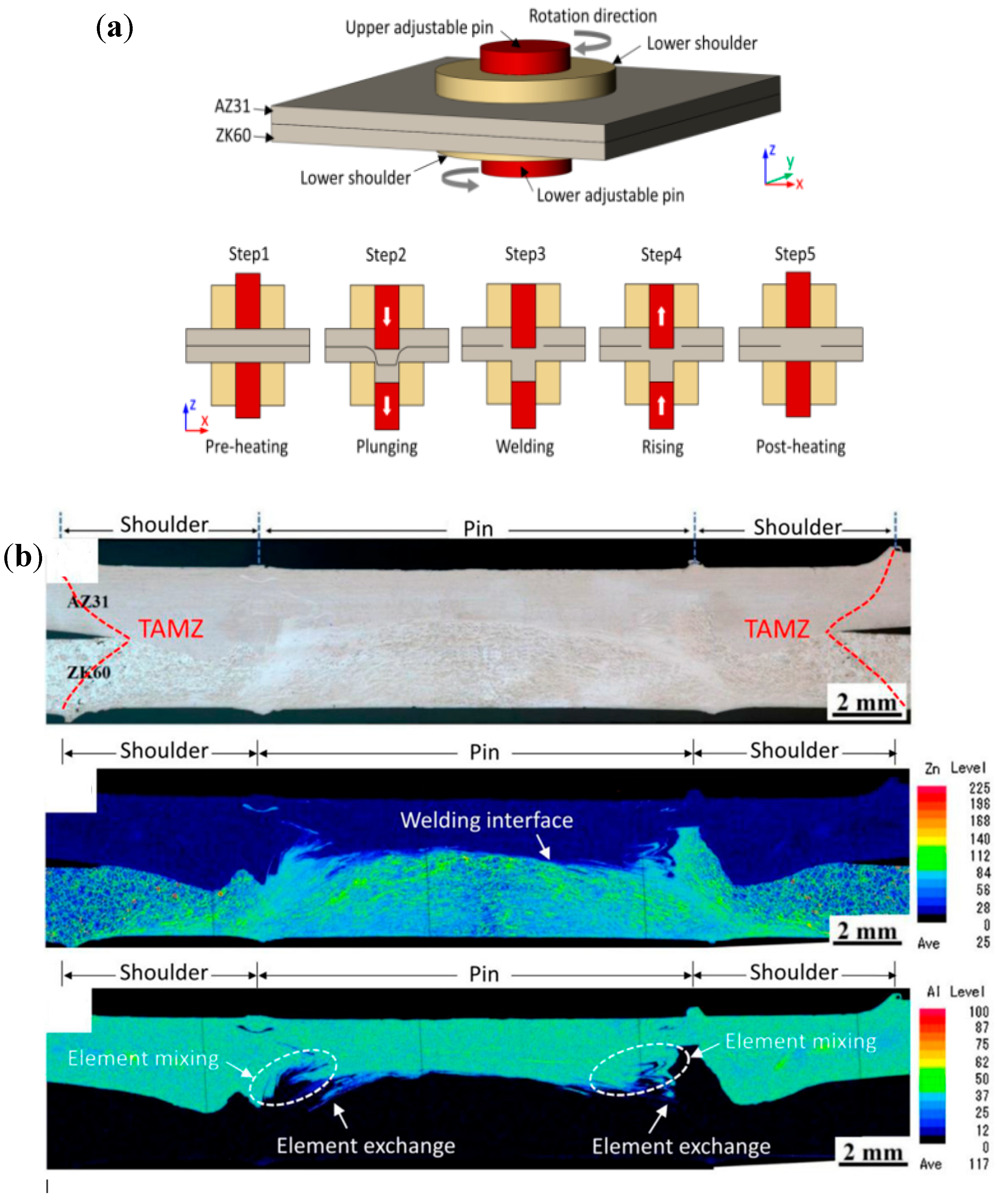
- Ke, W.C.; Oliveira, J.P.; Ao, S.S.; Teshime, F.B.; Chen, L.; Peng, B.; Zeng, Z. Thermal process and material flow during dissimilar double-sided friction stir spot welding of AZ31/ZK60 magnesium alloys. J. Mater. Res. Technol. 2022, 17, 1942–1954. [Google Scholar] [CrossRef]
- Abdullah, I.T.; Mejbel, M.K.; Al-bhadle, B.M.A. Double Stage Friction Stir Spot Extrusion Welding: A Novel Manufacturing Technique for Joining Sheets. Exp. Tech. 2023, 48, 323–342. [Google Scholar] [CrossRef]
- Fahmy, M.H.; Abdel-Aleem, H.A.; Abdel-Elraheem, N.A.; El-Kousy, M.R. Friction Stir Spot Welding of AA2024-T3 with Modified Refill Technique. Key Eng. Mater. 2020, 835, 274–287. [Google Scholar] [CrossRef]
- Fan, W.; Yang, X.; Chu, Q.; Li, W. An efficient synergistic double-sided friction stir spot welding method: A case study on process optimization, interfacial characteristics and mechanical properties of 2198-T8 aluminum-lithium alloy joints. J. Manuf. Process. 2024, 131, 213–232. [Google Scholar] [CrossRef]
- Pita, M. Investigation of the Effect of Tool Temperature on Microstructure, Hardness, and Wear Behaviour of Aluminium 6061-T6 Alloy Welded by the Friction Stir Welding Process. Mater. Des. Process Commun. 2023, 2023, 1795150. [Google Scholar] [CrossRef]
- Bolouri, A.; Fotouhi, M.; Moseley, W. A New Design for Friction Stir Spot Joining of Al Alloys and Carbon Fiber-Reinforced Composites. J. Mater. Eng. Perform. 2020, 29, 4913–4921. [Google Scholar] [CrossRef]
- Raturi, M.; Garg, A.; Bhattacharya, A. Tensile strength and failure of dissimilar friction stir welded joints between 6061-T6 and 2014-T6 aluminum alloys. Procedia Struct. Integr. 2019, 17, 495–502. [Google Scholar] [CrossRef]
- Badarinarayan, H.; Yang, Q.; Hunt, F. Effect of pin geometry on static strength of friction stir spot welds. In SAE Technical Papers; SAE International: Warrendale, PA, USA, 2008. [Google Scholar]
- Abdollahzadeh, A.; Bagheri, B.; Vaneghi, A.H.; Shamsipur, A.; Mirsalehi, S.E. Advances in simulation and experimental study on intermetallic formation and thermomechanical evolution of Al–Cu composite with Zn interlayer: Effect of spot pass and shoulder diameter during the pinless friction stir spot welding process. Proc. Inst. Mech. Eng. Part L J. Mater. Des. Appl. 2023, 237, 1475–1494. [Google Scholar] [CrossRef]
- Vaneghi, A.H.; Bagheri, B.; Shamsipur, A.; Mirsalehi, S.E.; Abdollahzadeh, A. Investigations into the formation of intermetallic compounds during pinless friction stir spot welding of AA2024-Zn-pure copper dissimilar joints. Weld. World 2022, 66, 2351–2369. [Google Scholar] [CrossRef]
- Hirasawa, S.; Badarinarayan, H.; Okamoto, K.; Tomimura, T.; Kawanami, T. Analysis of effect of tool geometry on plastic flow during friction stir spot welding using particle method. J. Mater. Process. Technol. 2010, 210, 1455–1463. [Google Scholar] [CrossRef]
- Sarikavak, Y. An advanced modelling to improve the prediction of thermal distribution in friction stir welding (FSW) for difficult to weld materials. J. Braz. Soc. Mech. Sci. Eng. 2021, 43, 4. [Google Scholar] [CrossRef]
- Hannachi, N.; Khalfallah, A.; Leitão, C.; Rodrigues, D. Thermo-mechanical modelling of the Friction Stir Spot Welding process: Effect of the friction models on the heat generation mechanisms. Proc. Inst. Mech. Eng. Part L J. Mater. Des. Appl. 2022, 236, 1464–1475. [Google Scholar] [CrossRef]
- Akbari, M.; Asadi, P.; Sadowski, T. A Review on Friction Stir Welding/Processing: Numerical Modeling. Materials 2023, 16, 5890. [Google Scholar] [CrossRef]
- Carr, G.E.; Biocca, N.; Lombera, G.A.; Urquiza, S.A. FEM modelling of the three stages of friction stir spot welding. Proc. Inst. Mech. Eng. Part C J. Mech. Eng. Sci. 2023, 237, 3483–3492. [Google Scholar] [CrossRef]
- Zhang, B.; Chen, X.; Pan, K.X.; Li, M.; Wang, J. Thermo-mechanical simulation using microstructure-based modeling of friction stir spot welded AA 6061-T6. J. Manuf. Process. 2019, 37, 71–81. [Google Scholar] [CrossRef]
- Chupradit, S.; Bokov, D.O.; Suksatan, W.; Landowski, M.; Fydrych, D.; Abdullah, M.E.; Derazkola, H.A. Pin angle thermal effects on friction stir welding of AA5058 aluminum alloy: CFD simulation and experimental validation. Materials 2021, 14, 7565. [Google Scholar] [CrossRef]
- Kumar, R.R.; Kumar, A.; Kumar, A.; Ansu, A.; Goyal, A.; Saxena, K.K.; Prakash, C.; Laxmi, J. Thermal simulation on friction stir welding of AA6061 aluminum alloy by computational fluid dynamics. Int. J. Interact. Des. Manuf. 2023, 18, 3495–3505. [Google Scholar] [CrossRef]
- Hassanifard, S.; Qiyasvand, A. Numerical Simulation of FSW and FSSW with Pinless Tool of AA6061-T6 Al Alloy by CEL Approach A. J. Solid Fluid Mech. 2018, 18, 45–55. [Google Scholar] [CrossRef]
- Yang, H.G. Numerical simulation on friction stir spot welding of alumimum alloy using SPH method. In Proceedings of the CSAE 2012—Proceedings, 2012 IEEE International Conference on Computer Science and Automation Engineering, Zhangjiajie, China, 25–27 May 2012; Volume 2, pp. 658–660. [Google Scholar] [CrossRef]
- Rashkovets, M.; Contuzzi, N.; Casalino, G. Modeling of Probeless Friction Stir Spot Welding of AA2024/AISI304 Steel Lap Joint. Materials 2022, 15, 8205. [Google Scholar] [CrossRef] [PubMed]
- Hannachi, N.; Khalfallah, A.; Leitao, C.; Rodrigues, D.M. A Comparative Study on the Physical and Mechanical Behavior of AA6082-T6 and AA5083-H116 Aluminum Alloys in Friction Stir Spot Welding. In International Conference on Advances in Mechanical Engineering and Mechanics; Lecture Notes in Mechanical Engineering; Springer: Cham, Switzerland, 2021; pp. 264–270. [Google Scholar] [CrossRef]
- Hannachi, N.; Khalfallah, A.; Leitão, C.; Rodrigues, D.M. Comparison Between ALE and CEL Finite Element Formulations to Simulate Friction Stir Spot Welding. In Advances in Mechanical Engineering, Materials and Mechanics; Lecture Notes in Mechanical Engineering; Springer: Berlin/Heidelberg, Germany, 2022; pp. 277–284. [Google Scholar] [CrossRef]
- Jo, D.S.; Kahhal, P.; Kim, J.H. Optimization of Friction Stir Spot Welding Process Using Bonding Criterion and Artificial Neural Network. Materials 2023, 16, 3757. [Google Scholar] [CrossRef] [PubMed]
- Chen, K.; Liu, X.; Ni, J. Thermal-mechanical modeling on friction stir spot welding of dissimilar materials based on Coupled Eulerian-Lagrangian approach. Int. J. Adv. Manuf. Technol. 2017, 91, 1697–1707. [Google Scholar] [CrossRef]
- Shobri, N.N.S.M.; Pedapati, S.R.; Awang, M. Simulation of Friction Stir Spot Welding of Copper and Aluminium During Plunging Phase. J. Phys. Conf. Ser. 2021, 2129, 012002. [Google Scholar] [CrossRef]
- Salloomi, K.N.; Al-Sumaidae, S. Coupled Eulerian–Lagrangian prediction of thermal and residual stress environments in dissimilar friction stir welding of aluminum alloys. J. Adv. Join. Process. 2021, 3, 100052. [Google Scholar] [CrossRef]
- Berger, E.; Miles, M.; Curtis, A.; Blackhurst, P.; Hovanski, Y. 2D Axisymmetric Modeling of Refill Friction Stir Spot Welding and Experimental Validation. J. Manuf. Mater. Process. 2022, 6, 89. [Google Scholar] [CrossRef]
- Janga, V.S.R.; Awang, M.; Pedapati, S.R. A Numerical Study on the Effect of Tool Speeds on Temperatures and Material Flow Behaviour in Refill Friction Stir Spot Welding of Thin AA7075-T6 Sheets. Materials 2023, 16, 3108. [Google Scholar] [CrossRef]
- Mofid, M.A.; Abdollah-Zadeh, A.; Ghaini, F.M.; Gür, C.H. Submerged friction-stir welding (SFSW) underwater and under liquid nitrogen: An improved method to join Al alloys to Mg alloys. Met. Mater. Trans. A Phys. Met. Mater. Sci. 2012, 43, 5106–5114. [Google Scholar] [CrossRef]
- Basak, S.; Mondal, M.; Anaman, S.Y.; Gao, K.; Hong, S.T.; Cho, H.H. Gas pocket-assisted underwater friction stir spot welding. J. Mater. Process. Technol. 2023, 320, 118100. [Google Scholar] [CrossRef]
- Bagheri, B.; Mahdian Rizi, A.A.; Abbasi, M.; Givi, M. Friction Stir Spot Vibration Welding: Improving the Microstructure and Mechanical Properties of Al5083 Joint. Metallogr. Microstruct. Anal. 2019, 8, 713–725. [Google Scholar] [CrossRef]
- Bagheri, B.; Abbasi, M.; Abdollahzadeh, A.; Moghaddam, A.O. Numerical Modeling and Experimental Analysis of Water Jet Spot Welding and Friction Stir Spot Welding: A Comparative Study. J. Mater. Eng. Perform. 2021, 30, 1454–1471. [Google Scholar] [CrossRef]
- Rostamiyan, Y.; Seidanloo, A.; Sohrabpoor, H.; Teimouri, R. Experimental studies on ultrasonically assisted friction stir spot welding of AA6061. Arch. Civ. Mech. Eng. 2015, 15, 335–346. [Google Scholar] [CrossRef]
- Bagheri, B.; Abbasi, M.; Abdollahzadeh, A.; Omidvar, H. Advanced Approach to Modify Friction Stir Spot Welding Process. Met. Mater. Int. 2020, 26, 1562–1573. [Google Scholar] [CrossRef]
- Ji, S.D.; Li, Z.W.; Ma, L.; Yue, Y.M.; Gao, S.S. Investigation of Ultrasonic Assisted Friction Stir Spot Welding of Magnesium Alloy to Aluminum Alloy. Strength Mater. 2016, 48, 2–7. [Google Scholar] [CrossRef]
- Bagheri, B.; Abbasi, M.; Hamzeloo, R. The investigation into vibration effect on microstructure and mechanical characteristics of friction stir spot vibration welded aluminum: Simulation and experiment. Proc. Inst. Mech. Eng. Part C J. Mech. Eng. Sci. 2020, 234, 1809–1822. [Google Scholar] [CrossRef]
- Bagheri, B.; Abbasi, M.; Givi, M. Effects of Vibration on Microstructure and Thermal Properties of Friction Stir Spot Welded (FSSW) Aluminum Alloy (Al5083). Int. J. Precis. Eng. Manuf. 2019, 20, 1219–1227. [Google Scholar] [CrossRef]
- Lin, W.; Luo, H. Robotic Welding. In Handbook of Manufacturing Engineering and Technology; Springer: London, UK, 2014; pp. 1–36. [Google Scholar]
- Kolegain, K.; Leonard, F.; Chevret, S.; Attar, A.B.; Abba, G. Off-line path programming for three-dimensional robotic friction stir welding based on Bézier curves. Ind. Robot 2018, 45, 669–678. [Google Scholar] [CrossRef]
- Gurdal, O.; Rae, B.; Zonuzi, A.; Ozturk, E. Vision-assisted robotic finishing of friction stir-welded corner joints. Procedia Manuf. 2019, 40, 70–76. [Google Scholar] [CrossRef]
- Lakshmi Balasubramaniam, G.; Boldsaikhan, E.; Fukada, S.; Fujimoto, M.; Kamimuki, K. Effects of Refill Friction Stir Spot Weld Spacing and Edge Margin on Mechanical Properties of Multi-Spot-Welded Panels. J. Manuf. Mater. Process. 2020, 4, 55. [Google Scholar] [CrossRef]
- Okada, H.; Kamimuki, K.; Yoshikawa, S.; Fukada, S. Refill Friction Spot Joining for Aerospace Application. In SAE Technical Papers; SAE International: Warrendale, PA, USA, 2015. [Google Scholar]
- Okada, H.; Kamimuki, K.; Fujimoto, M. Assembly Study of Refill FSSW. SAE Int. J. Aerosp. 2013, 6, 299–304. [Google Scholar] [CrossRef]
- Spot Friction Welding Systems. Available online: https://coldwatermachine.com/spot-friction-welding/ (accessed on 5 June 2024).
- Murr, L.E. A review of FSW research on dissimilar metal and alloy systems. J. Mater. Eng. Perform. 2010, 19, 1071–1089. [Google Scholar] [CrossRef]
- Bagheri, B.; Abbasi, M.; Abdollahzadeh, A.; Mirsalehi, S.E. Effect of second-phase particle size and presence of vibration on AZ91/SiC surface composite layer produced by FSP. Trans. Nonferrous Met. Soc. China 2020, 30, 905–916. [Google Scholar] [CrossRef]
- Sharma, V.; Prakash, U.; Kumar, B.V.M. Surface composites by friction stir processing: A review. J. Mater. Process. Technol. 2015, 224, 117–134. [Google Scholar] [CrossRef]
- Kumar, A.; Singh, B.; Kumar, P. Effect of friction stir processing on the wear rate of as-cast AZ91D Magnesium alloy. Mater. Today Proc. 2021, 46, 10384–10388. [Google Scholar] [CrossRef]
- Salehi, M.; Saadatmand, M.; Mohandesi, J.A. Optimization of process parameters for producing AA6061/SiC nanocomposites by friction stir processing. Trans. Nonferrous Met. Soc. China 2012, 22, 1055–1063. [Google Scholar] [CrossRef]
- Varunraj, S.; Ruban, M. Investigation of the microstructure and mechanical properties of AA6063 and AA7075 dissimilar aluminium alloys by friction stir welding process. Mater. Today Proc. 2022, 68, 1654–1657. [Google Scholar] [CrossRef]
- Jafari, H.; Mansouri, H.; Honarpisheh, M. Investigation of residual stress distribution of dissimilar Al-7075-T6 and Al-6061-T6 in the friction stir welding process strengthened with SiO2 nanoparticles. J. Manuf. Process. 2019, 43, 145–153. [Google Scholar] [CrossRef]
- Suresh, S.; Natarajan, E.; Franz, G.; Rajesh, S. Differentiation in the SiC Filler Size Effect in the Mechanical and Tribological Properties of Friction-Spot-Welded AA5083-H116 Alloy. Fibers 2022, 10, 109. [Google Scholar] [CrossRef]
- Asadollahi, M.; Khalkhali, A. Optimization of mechanical and microstructural properties of friction stir spot welded AA 6061-T6 reinforced with SiC nanoparticles. Mater. Res. Express 2018, 5, 116517. [Google Scholar] [CrossRef]
- Rajendran, C.; Sonar, T.; Ivanov, M.; Senthil Kumar, P.; Amarnath, V.; Lokanadham, R. Optimization of friction stir spot welding parameters for joining dissimilar AZ31B magnesium alloy and AA6061 aluminium alloy using response surface methodology. Int. J. Interact. Des. Manuf. 2023, 19, 115–126. [Google Scholar] [CrossRef]
- Behrouz Bagheri, A.A.; Shamsipur, A. A different attempt to analysis friction stir spot welding of AA5083-copper alloys. Mater. Sci. Technol. 2023, 39, 1083–1089. [Google Scholar] [CrossRef]
- Mohd Isa, M.S.; Muhamad, M.R.; Yusof, F.; Yusoff, N.; Brytan, Z.; Suga, T.; Morisada, Y.; Fujii, H. Improved mechanical and electrical properties of copper-aluminum joints with highly aligned graphene reinforcement via friction stir spot welding. J. Mater. Res. Technol. 2023, 24, 9203–9215. [Google Scholar] [CrossRef]
- Suresh, S.; Elango, N.; Venkatesan, K.; Lim, W.H.; Palanikumar, K.; Rajesh, S. Sustainable friction stir spot welding of 6061-T6 aluminium alloy using improved non-dominated sorting teaching learning algorithm. J. Mater. Res. Technol. 2020, 9, 11650–11674. [Google Scholar] [CrossRef]
- Abdollahzadeh, A.; Bagheri, B.; Shamsipur, A. Development of Al/Cu/SiC bimetallic nano-composite by friction stir spot welding. Mater. Manuf. Process. 2023, 38, 1416–1425. [Google Scholar] [CrossRef]
- Rafiee, A.; Nickabadi, S.; Nobarian, M.A.; Tagimalek, H.; Khaatami, H. Experimental Investigation Joining Al 5083 and High-density Polyethylen by Protrusion Friction Stir Spot Welding Containing Nanoparticles using Taguchi Method. Int. J. Eng. Trans. B Appl. 2022, 35, 1144–1153. [Google Scholar] [CrossRef]
- Suresh, S.; Venkatesan, K.; Natarajan, E.; Rajesh, S. Performance Analysis of Nano Silicon Carbide Reinforced Swept Friction Stir Spot Weld Joint in AA6061-T6 Alloy. Silicon 2021, 13, 3399–3412. [Google Scholar] [CrossRef]
- Sadeghi, B.; Abbasi, H.; Atapour, M.; Shafiee, S.; Cavaliere, P.; Marfavi, Z. Friction stir spot welding of TiO2 nanoparticle-reinforced interstitial free steel. J. Mater. Sci. 2020, 55, 12458–12475. [Google Scholar] [CrossRef]
- Suresh, S.; Venkatesan, K.; Rajesh, S. Optimization of process parameters for friction stir spot welding of AA6061/Al2O3 by Taguchi method. AIP Conf. Proc. 2019, 2128, 030018. [Google Scholar]
- Wu, D.; Shen, J.; Lv, L.; Wen, L.; Xie, X. Effects of nano-SiC particles on the FSSW welded AZ31 magnesium alloy joints. Mater. Sci. Technol. 2017, 33, 998–1003. [Google Scholar] [CrossRef]
- Hong, S.T.; Das, H.; Oh, H.S.; Nasim, M.N.E.A.N.; Chun, D.M. Combination of nano-particle deposition system and friction stir spot welding for fabrication of carbon/aluminum metal matrix composite joints of dissimilar aluminum alloys. CIRP Ann. 2017, 66, 261–264. [Google Scholar] [CrossRef]
- Fereiduni, E.; Movahedi, M.; Baghdadchi, A. Ultrahigh-strength friction stir spot welds of aluminium alloy obtained by Fe3O4 nanoparticles. Sci. Technol. Weld. Join. 2018, 23, 63–70. [Google Scholar] [CrossRef]
- Tebyani, S.F.; Dehghani, K. Friction stir spot welding of interstitial free steel with incorporating silicon carbide nanopowders. Int. J. Adv. Manuf. Technol. 2015, 79, 343–350. [Google Scholar] [CrossRef]
- Paidar, M.; Sarab, M.L. Friction stir spot welding of 2024-T3 aluminum alloy with SiC nanoparticles. J. Mech. Sci. Technol. 2016, 30, 365–370. [Google Scholar] [CrossRef]
- Jeon, C.-S.; Jeong, Y.-H.; Hong, S.-T.; Hasan, M.T.; Tien, H.N.; Hur, S.-H.; Kwon, Y. Mechanical properties of graphite/aluminum metal matrix composite joints by friction stir spot welding. J. Mech. Sci. Technol. 2014, 28, 499–504. [Google Scholar] [CrossRef]
- Bagheri, B.; Alizadeh, M.; Mirsalehi, S.E.; Ahamsipur, A.; Abdollahzdeh, A. Nanoparticles Addition in AA2024 Aluminum/Pure Copper Plate: FSSW Approach, Microstructure Evolution, Texture Study, and Mechanical Properties. JOM 2022, 74, 4420–4433. [Google Scholar] [CrossRef]
- Chaudhary, N.; Singh, S.; Garg, M.P.; Garg, H.K.; Sharma, S.; Li, C.; Tag Eldin, E.M.; El-Khatib, S. Parametric Optimisation of Friction-Stir-Spot-Welded Al 6061-T6 Incorporated with Silicon Carbide Using a Hybrid WASPAS–Taguchi Technique. Materials 2022, 15, 6427. [Google Scholar] [CrossRef]
- Bagheri, B.; Shamsipur, A.; Abdollahzadeh, A.; Mirsalehi, S.E. Investigation of SiC Nanoparticle Size and Distribution Effects on Microstructure and Mechanical Properties of Al/SiC/Cu Composite during the FSSW Process: Experimental and Simulation. Met. Mater. Int. 2023, 29, 1095–1112. [Google Scholar] [CrossRef]
- Hassanifard, S.; Ghiasvand, A.; Varvani-Farahani, A. Fatigue Response of Aluminum 7075-T6 Joints through Inclusion of Al2O3 Particles to the Weld Nugget Zone during Friction Stir Spot Welding. J. Mater. Eng. Perform. 2022, 31, 1781–1790. [Google Scholar] [CrossRef]
- Suresh, S.; Natarajan, E.; Markandan, K.; Sudhagar, S.; Anbuchezhiyan, G.; Elayaraja, R. Strategic enhancement of joint strength in dissimilar Al/Mg alloys: A workable approach for aerospace application. Discov. Mater. 2025, 5, 23. [Google Scholar] [CrossRef]
- Bagheri, B.; Alizadeh, M.; Mirsalehi, S.E.; Shamsipur, A.; Abdollahzadeh, A. The effect of rotational speed and dwell time on Al/SiC/Cu composite made by friction stir spot welding. Weld. World 2022, 66, 2333–2350. [Google Scholar] [CrossRef]
- Heidarzadeh, A.; Mironov, S.; Kaibyshev, R.; Cam, G.; Simar, A.; Gerlich, A.; Khodabakhshi, F.; Mostafaei, A.; Field, D.P.; Robson, J.D.; et al. Friction stir welding/processing of metals and alloys: A comprehensive review on microstructural evolution. Prog. Mater. Sci. 2021, 117, 100752. [Google Scholar] [CrossRef]
- Badkoobeh, F.; Mostaan, H.; Rafiei, M.; Bakhsheshi-Rad, H.R.; Berto, F. Friction stir welding/processing of mg-based alloys: A critical review on advancements and challenges. Materials 2021, 14, 15–17. [Google Scholar] [CrossRef] [PubMed]
- Tanvir Singh, S.K.T.; Shukla, D.K. Novel method of nanoparticle addition for friction stir welding of aluminium alloy. Adv. Mater. Process. Technol. 2022, 8, 1160–1172. [Google Scholar] [CrossRef]
- Anand, R.; Sridhar, V.G. Effects of SiC and Al2O3 Reinforcement of Varied Volume Fractions on Mechanical and Micro Structure Properties of Interlock FSW Dissimilar Joints AA7075-T6-AA7475-T7. Silicon 2021, 13, 3017–3029. [Google Scholar] [CrossRef]
- Balamurugan, M.; Gopi, S.; Mohan, D.G. Influence of tool pin profiles on the filler added friction stir spot welded dissimilar aluminium alloy joints. Mater. Res. Express 2021, 8, 096531. [Google Scholar] [CrossRef]
- Liu, S.; Zhang, S.; Vaira Vignesh, R.; Oladimeji Ojo, O.; Mehrez, S.; Mohanavel, V.; Paidar, M. Probe-less friction stir spot processing (PFSSP) of AA5754/AA5083 joint by adding the B4C ceramics: Effect of shoulder features on mechanical properties and tribological behavior. Vacuum 2023, 207, 111542. [Google Scholar] [CrossRef]
- Ikumapayi, O.M.; Akinlabi, E.T. Recent Advances In Keyhole Defects Repairs Via Refilling Friction Stir Spot Welding. Mater. Today Proc. 2019, 18, 2201–2208. [Google Scholar] [CrossRef]
- Singh, V.P.; Patel, S.K.; Ranjan, A.; Kuriachen, B. Recent research progress in solid state friction-stir welding of aluminium–magnesium alloys: A critical review. J. Mater. Res. Technol. 2020, 9, 6217–6256. [Google Scholar] [CrossRef]
- Cao, X.; Jahazi, M. Effect of tool rotational speed and probe length on lap joint quality of a friction stir welded magnesium alloy. Mater. Des. 2011, 32, 1–11. [Google Scholar] [CrossRef]
- Liu, H.; Zhao, Y.; Su, X.; Tu, L.; Hou, J. Microstructural Characteristics and Mechanical Properties of Friction Stir Spot Welded 2A12-T4 Aluminum Alloy. Adv. Mater. Sci. Eng. 2013, 2013, 719306. [Google Scholar] [CrossRef]
- Rajak, D.; Pagar, D.; Menezes, P.; Eyvazian, A. Friction-based welding processes: Friction welding and friction stir welding. J. Adhes. Sci. Technol. 2020, 34, 2613–2637. [Google Scholar] [CrossRef]
- Shirazi, H.; Kheirandish, S.; Safarkhanian, M.A. Effect of process parameters on the macrostructure and defect formation in friction stir lap welding of AA5456 aluminum alloy. Meas. J. Int. Meas. Confed. 2015, 76, 62–69. [Google Scholar] [CrossRef]
- Palanikumar, K.; Natarajan, E.; Suresh, S.; Mohan, D.G.; Prakash, C.; Kaur, K. Prospects of friction stir processed Mg alloys and composites-Reviews and suggestions. J. Mater. Res. Technol. 2024, 31, 971–997. [Google Scholar] [CrossRef]
- Suresh, S.; Natarajan, E.; Mohan, D.G.; Ang, C.K.; Sudhagar, S. Depriving friction stir weld defects in dissimilar aluminum lap joints. Proc. Inst. Mech. Eng. Part E J. Process Mech. Eng. 2024. [Google Scholar] [CrossRef]
- Lunetto, V.; De Maddis, M.; Russo Spena, P. Pre-hole friction stir spot welding of dual-phase steels and comparison with resistance spot welding, conventional and pinless friction stir spot welding. Int. J. Adv. Manuf. Technol. 2023, 129, 2333–2349. [Google Scholar] [CrossRef]
- Dong, Z.; Yang, K.; Ren, R.; Wang, G.; Wang, L.; Lu, Z. Friction Stir Lap Welding 0.8-mm-Thick 2024 Aluminum Alloy with the Assistance of Stationary Shoulder. J. Mater. Eng. Perform. 2019, 28, 6704–6713. [Google Scholar] [CrossRef]
- Sharma, A.; Sharma, V.M.; Gugaliya, A.; Rai, P.; Pal, S.K.; Paul, J. Friction stir lap welding of AA6061 aluminium alloy with a graphene interlayer. Mater. Manuf. Process. 2020, 35, 258–269. [Google Scholar] [CrossRef]


| FSSW Variant | Tool Movement | Key Feature | Weld Quality | Application Notes |
|---|---|---|---|---|
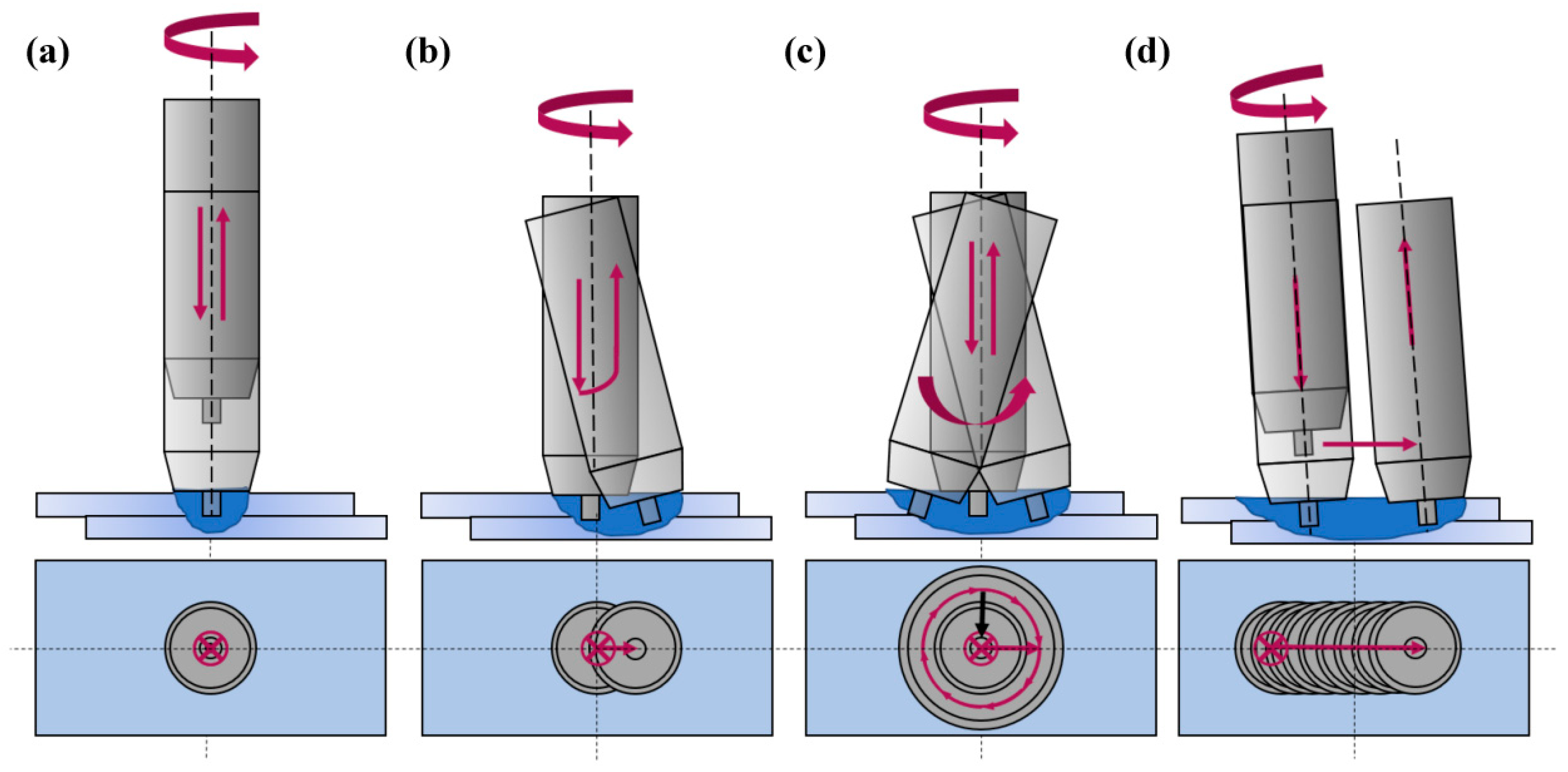
| Conventional FSSW | Vertical plunge and retract | Leaves keyhole | Good, keyhole present | Widely used; automotive panels |
| Swept FSSW (SweFSSW) | Tool swings in a circular path before retraction | Enlarged weld area | Improved over conventional | Used in aerospace and automotive |
| Refill FSSW (RFSSW) | Tool refills material after joining | Eliminates keyhole | Excellent | Aerospace-grade joints |
| Swing FSSW (SwiFSSW) | Swing-like tool motion post-plunge | Enlarges weld area | Enhanced | Improves bonding area and strength |
| Stitch FSSW (StiFSSW) | Tool traverses short distance | Creates multiple weld points | High | Stitch welds for load-bearing joints |
| Base Material | Plate Thick | Reinforced Particle and Their Size | FSSW | Process Parameters | Ref. |
|---|---|---|---|---|---|
| Aluminum-copper | 3 mm | 50 nm and 250 nm SiC particles | FSSW | [157] | |
| AA5083 + HD-PE | 2 mm | Al2O3, TiO2, SiO2 | FSSW | TRS, DT, VF | [158] |
| AA6061-T6 | 2 mm | SiC—50 nm | SweFSSW | GHD, TRS, TTS | [159] |
| AA7075-T6 | 2 mm | Al2O3—30 nm | FSSW | TRS | [34] |
| Interstitial free (IF) steel | 0.7 mm | TiO2—35 nm | FSSW | TRS, TPD, DT and VF | [160] |
| AA6061-T6 | 2 mm | Al2O3—30 nm | SweFSSW | GHD, TRS, TTS | [156] |
| AA6061-T6 | 2 mm | Al2O3—30 nm | FSSW | TRS, TPR and DT | [161] |
| AA6061-T6 | 2 mm | SiC—50 nm | FSSW | TRS, VF and DT | [36] |
| AA6061-T6 | 3 mm | 45 to 65 nm | FSSW | TRS, VF and DT | [152] |
| AZ31-B | 2 mm | SiC—40 nm | FSSW | TRS, TPR and DT | [162] |
| AA5052-H32/AA6061-T4 | 3 mm | graphite powder—10 µm | FSSW | TRS, TPR, TPD and DT | [163] |
| AA5083-H321 | 3 mm | Fe3O4—20 nm | FSSW | TRS and DT | [164] |
| Interstitial free (IF) steel | 0.7/1 mm | SiC—25 nm | FSSW | TRS, DT | [165] |
| AA2024-T3 | 1.6 mm | SiC—30 nm | FSSW | TRS, DT | [166] |
| AA5052-H32 | 3 mm | Graphite (15 µm) | FSSW | TRS, TPD | [167] |
| AA2024 + Aluminum/pure Copper | 2 mm | SiC | FSSW | TRS, DT, VF | [168] |
| AA6061-T6 | 3 mm | SiC—45 µm | FSSW | TRS, DT and GHD | [169] |
Disclaimer/Publisher’s Note: The statements, opinions and data contained in all publications are solely those of the individual author(s) and contributor(s) and not of MDPI and/or the editor(s). MDPI and/or the editor(s) disclaim responsibility for any injury to people or property resulting from any ideas, methods, instructions or products referred to in the content. |
© 2025 by the authors. Licensee MDPI, Basel, Switzerland. This article is an open access article distributed under the terms and conditions of the Creative Commons Attribution (CC BY) license (https://creativecommons.org/licenses/by/4.0/).
Share and Cite
Subramanian, S.; Natarajan, E.; Khalfallah, A.; Muthukutti, G.P.; Beygi, R.; Louhichi, B.; Sengottuvel, R.; Ang, C.K. Current Trends and Emerging Strategies in Friction Stir Spot Welding for Lightweight Structures: Innovations in Tool Design, Robotics, and Composite Reinforcement—A Review. Crystals 2025, 15, 556. https://doi.org/10.3390/cryst15060556
Subramanian S, Natarajan E, Khalfallah A, Muthukutti GP, Beygi R, Louhichi B, Sengottuvel R, Ang CK. Current Trends and Emerging Strategies in Friction Stir Spot Welding for Lightweight Structures: Innovations in Tool Design, Robotics, and Composite Reinforcement—A Review. Crystals. 2025; 15(6):556. https://doi.org/10.3390/cryst15060556
Chicago/Turabian StyleSubramanian, Suresh, Elango Natarajan, Ali Khalfallah, Gopal Pudhupalayam Muthukutti, Reza Beygi, Borhen Louhichi, Ramesh Sengottuvel, and Chun Kit Ang. 2025. "Current Trends and Emerging Strategies in Friction Stir Spot Welding for Lightweight Structures: Innovations in Tool Design, Robotics, and Composite Reinforcement—A Review" Crystals 15, no. 6: 556. https://doi.org/10.3390/cryst15060556
APA StyleSubramanian, S., Natarajan, E., Khalfallah, A., Muthukutti, G. P., Beygi, R., Louhichi, B., Sengottuvel, R., & Ang, C. K. (2025). Current Trends and Emerging Strategies in Friction Stir Spot Welding for Lightweight Structures: Innovations in Tool Design, Robotics, and Composite Reinforcement—A Review. Crystals, 15(6), 556. https://doi.org/10.3390/cryst15060556