Abstract
Higher-order reflections from a cholesteric liquid crystal have been investigated for a long time after early observations of an oblique incidence of light. Even with the restriction of the required oblique geometry, wavelength tuning would make this property very attractive for photonic applications in the near-UV range of the electromagnetic spectrum. Unfortunately, this is quite difficult to achieve in cholesterics, and it has been obtained in special configurations that lead to the deformation of the helical structure. We show here that a new opportunity is provided by heliconical cholesteric liquid crystals and demonstrate that second-order Bragg resonance with high reflectivity and a narrow band can be produced by a light beam with intensity high enough to give rise to a significant optical torque with the consequent distortion of the helical structure. Exploiting the well-known properties of heliconical cholesterics under electric fields, we also demonstrate that the easy tuning of the second-order reflection band is achieved in the near-UV range.
1. Introduction
Second-order Bragg reflection from a cholesteric liquid crystal (CLC) was observed by Berreman and Scheffer in the first experiments on single-domain CLC samples for the oblique incidence of light [1,2]. This peculiar optical property of CLCs becomes attractive for several reasons: the possibility of generating a reflection band in the blue or near-UV range of the electromagnetic spectrum, the provision of a reflection band much narrower than the first-order Bragg resonance, and a much faster response time [3,4]. Of course, providing the additional property of the continuous electrical tuning of the higher-order reflection over a broad wavelength range makes this phenomenon more interesting for photonic applications. However, the extended investigations carried out on this subject have shown that the electrical tuning of CLC Bragg resonance is not easy to achieve. To overcome these difficulties, different configurations have been proposed.
Using CLC planar cells with interdigitated electrodes on the boundaries, second- and third-order reflection bands were observed over a critical value of the applied field [4,5]. The limit of this configuration is the need for a quite large voltage to be applied, the broad reflection spectrum, and the red-shifting due to the helix unwinding.
A different approach has been proposed by D.J. Broer and coworkers [6] using CLC polymers, where it is shown that deformation of the helical structure gives rise to higher-order reflections with an efficiency dependent on the strength of deformation. This result is quite important since it clarifies the origin of the appearance of the higher-order reflections due to the application of an electric field to the CLC structure.
A more recent paper by K.M. Lee et al. [7] reports the formation of higher-order reflections without the need for interdigitated electrodes or the involvement of polymerization process using polymer-stabilized CLCs (PSCLCs). In this case, the spectral position of the second-order reflection is determined by the concentration of chiral dopant and can be controlled by an applied electric field.
A breakthrough in the tunability of the Bragg diffraction over the entire visible spectrum has been represented in the past decade by the discovery of the “oblique helicoidal structure” (ChOH): a special configuration of CLC occurring when the condition is fulfilled and an electric field in a range of values within two critical values () is applied along the helix direction. Under these conditions, the stable structure is given by the molecular director rotating on a conical surface around the helical axis, thus forming the so-called “heliconical cholesteric liquid crystal” [8,9,10,11,12]. (Conventional definitions for the bend elastic constant and the twist elastic constant are used above).
Due to the presence of a director tilt angle with respect to the helix axis in the conical structure, easy modulation of the helix pitch becomes possible in ChOH, thus allowing for tuning the Bragg resonance over the whole visible spectrum by scanning a low-frequency electric field over fractions of V/μm [8,9,10]. This property makes this configuration extremely interesting for developing tunable photonic devices, overcoming a major obstacle present in the usual planar configuration of CLCs. For this reason, it also stimulates the investigation focused on conditions allowing for the generation of higher-order reflections. A recent report highlights many unexpected features of reflections originated by ChOH for the oblique incidence of the incoming light, analyzing (in much detail) the reflection bands originated by the pitch of the helical structure and those originated by the fractions , , and , with spectral location determined by the incidence angle and the applied voltage [13,14].
On the other hand, the bend deformation present in ChOH allows for efficient coupling between the optical field and the molecular director and gives rise to light-induced optical reorientation when light intensity is high enough to provide an effective optical torque [15]. This effect can produce strong nonlinear behavior in the propagation of the exciting light beam [16,17,18]. The modification of the transmission spectrum occurring during light propagation leads to self-induced oscillations on the edges of the reflection band and the broadening of the Bragg resonance, which becomes unstable and disappears at high intensities, underlying a strong light-induced deformation of the helical structure [19]. Additionally, the inclusion of photosensitive compounds in the material composition has been demonstrated to be effective in controlling the reflection band in ChOH [20], thus providing another method to induce a nonlinear light propagation.
As a consequence, taking into account the results mentioned above concerning reflection bands in CLCs and ChOH, we should expect the appearance of higher-order reflection peaks in ChOH even for normal incidences of light when nonlinear optical reorientation is effective.
In this paper, we show that distortion of the helical structure induced by optical reorientation leads to higher-order narrow reflection peaks for light normally impinging on a ChOH sample. The second-order Bragg resonance gives rise to significant and stable reflectivity (>0.5). Additionally, broad wavelength tuning is possible in the near-UV range, providing new features to develop tunable UV filters for photonic applications.
2. Theoretical Approach and Method
We give here a brief summary of the main steps of the approach for calculating the optical properties for a light beam travelling through a ChOH sample in the presence of an effective torque induced by the optical field on the molecular director. Details can be found in previous publications [17,18,19].
The starting point is the dielectric permittivity matrix at an optical frequency of ChOH, written as
Here, , , , where, as usual, and are the dielectric permittivities parallel and perpendicular to the director in the local frame. The sample considered is formed of a large number of sublayers (identified by the number, each of them with constant optical parameters, and the calculation is based on Ambartsumian’s layer-addition modified method, which allows for the recalculation of the optical field after traveling through each sublayer based on the field propagation equations.
This method provides the reflection coefficient , the transmission coefficient , and the light intensity of the wave travelling in the ChOH sample . Here is the total wave field arising in the ChOH layer at the point. The method of this calculation in all detail is described in [21].
The calculation has been performed both for the diffracting eigenmode with the circular polarization with the same handedness of the ChOH helix, and for the non-diffracting mode with circular polarization with opposite handedness. The light is impinging at normal incidence, where intensity . In this way, we use the normalized intensity , considering, in the first step of the calculation (j = 1), the effective applied field to be [15,16,17,18,19].
with the helix pitch and .
Here, is the low-frequency (static) field necessary to stabilize the heliconical structure, is the dielectric anisotropy at optical frequencies, and is the value at low frequencies.
The calculation allows obtaining to be used in the next steps to provide the new effective field . This allows us to obtain the new angle and pitch distribution:
Thus, the reflectivity and transmittivity of the ChOH sample are obtained for each impinging intensity.
The material parameters chosen for the calculation are the same reported in ref. [10] and used in our former calculations. They refer to a multi-component composition made by a mixture of flexible dimers M (Merck), a mixture of rod-like mesogens E7 (Merck), heptane CB7CB, and a chiral dopant S811 (Merck) with the following weight proportion M:E7:CB7CB:S811 = 45.5:30.3:20.2:4.0. Details on the material are reported in [10]. Then, we have , , , , and the unperturbated helix pitch is = 1400 nm, with critical fields and . The static field applied along the helix direction is . In our calculations, all the above-mentioned sublayers have the same thickness: d1 = d2 = d3 =…= dL = 8 nm.
We remark that computer programs were compiled in Visual Basic and debugged by the authors, and the graphs were built using the Excel 16.89 and MATLAB R2022a programs.
3. Results and Discussion
In Figure 1, the reflection spectra for a 20 μm thick sample are reported for two values of the impinging intensity. At we observe the usual Bragg resonance with a peak located near and a bandwidth of about . At , the Bragg spectrum is reduced and suffers a slight blue shift and large broadening to more than , while a second peak with significant reflectivity at the second harmonic wavelength of the original Bragg peak appears. This phenomenon is evident in the corresponding Figure 2, where the spectrum evolution is reported versus the parameter , counting the steps of the calculation that measures the elapsed time (using the response time of the material as the unit [19]). The spectrum calculated at shows that as soon as the main resonance broadens due to the nonlinear optical reorientation effect, additional higher-order resonances appear. In the following, we focus on the second-order resonance, because the increasing UV absorption at shorter wavelengths may affect the actual experimental observation of the higher-order reflections, depending on the chemical structure of the mixture components [22,23].
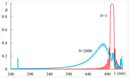
Figure 1.
Reflectivity vs. wavelength for a sample thickness , applied static field with material parameters indicated in the text, and two different values of the light intensity: red curve , blue curve . The step index (see text).
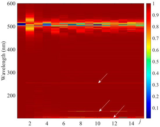
Figure 2.
The transmission spectra vs. the step-index j. Colors show the normalized value of the transmittivity. The index j is proportional to the elapsed time (see text). Light intensity , and the other parameters are as in Figure 1. Arrows indicate the presence of higher-order resonances.
Driven by this result, we have studied the main features of this phenomenon. In Figure 3, we report the reflectivity of the second-order Bragg diffraction for increasing values of the impinging light intensity. We see that it is barely present at , reaching a significant value at and over at , even if this last value is not stable (as we will show later). A very important feature of this resonance is the bandwidth being much narrower than the first-order Bragg resonance: about . It is quite interesting to understand the characteristics of the process, and the results are shown in Figure 4, where the second-order resonance is reported at for increasing values of the step parameter . We observe that the maximum value is achieved for , while relaxation and stabilization for a lower value of reflectivity occur for higher values of , i.e., on a longer time scale.
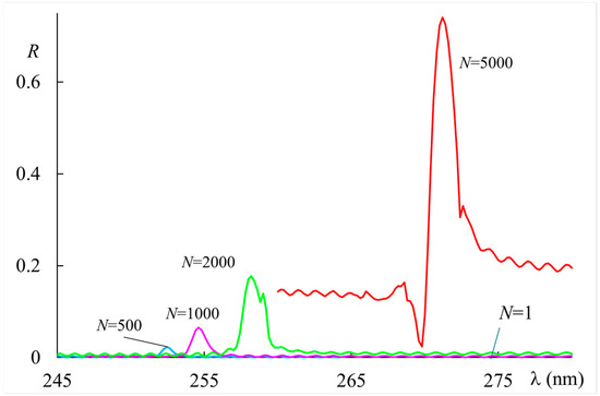
Figure 3.
Reflectivity vs. wavelength of the second-order Bragg resonance for a sample thickness
for increasing values of impinging light intensity. The applied static field with material parameters indicated in the text. The step index (see text).
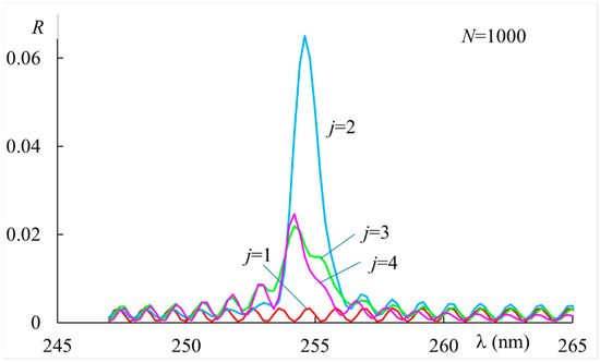
Figure 4.
Reflectivity vs. wavelength of the second-order Bragg resonance for a sample thickness at for increased step-index . The index j is proportional to the elapsed time (see text). The applied static field , with material parameters indicated in the text.
Quite different is the behavior at a somewhat high intensity (), as shown in Figure 5. In this case, we have a well-defined peak and high reflectivity for (over 0.60), but it disappears for higher values of because the system becomes unstable and the spoiling of the Bragg resonance occurs, as already reported [19].
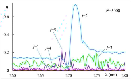
Figure 5.
Reflectivity vs. wavelength of the second-order Bragg resonance for a sample thickness at for increased step-index . The index j is proportional to the elapsed time (see text). The applied static field , with material parameters indicated in the text.
We have also checked the effect of sample thickness on the reflectivity of the second-order resonance. We chose a value for the light intensity () that leads to a significant reflectivity while allowing for the stabilization of the structure. These data are reported in Figure 6 for three different values of the sample thickness. They show an increase in reflectivity accompanied by an increased background around the peak.
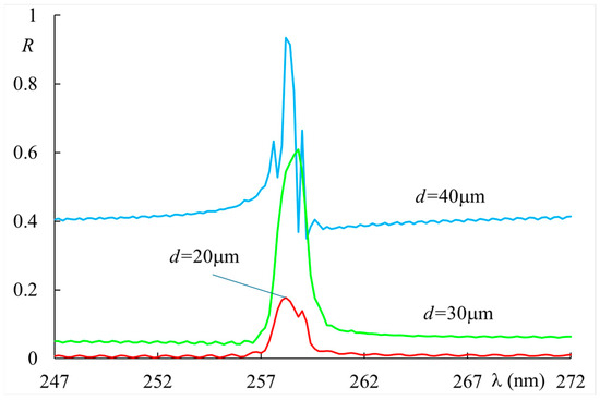
Figure 6.
Reflectivity vs. wavelength of the second-order Bragg resonance for increasing values of the sample thickness at . The applied static field , with material parameters indicated in the text.
The presented results are easily explained, taking into account the effect of the induced optical reorientation on the propagation of the light beam. We have previously demonstrated oscillations and the spoiling of the Bragg resonance induced by light in ChOH. This is due to a transition from a stable conical structure to a disordered system occurring by increasing the light intensity to a level high enough to produce a significant optical torque on the molecular director. We have shown that the shift and broadening of the Bragg resonance is accompanied by side-band oscillations, corresponding to the strong distortion of the helical structure, still identified by a central peak. On the other hand, we remind readers in the introduction that higher-order Bragg reflections can be originated by an inhomogeneously twisted director in a CLC structure [6]. Therefore, the observed second-order Bragg reflection in the figures reported is understood as having originated from the helix distortion. The time evolution of the spectrum at the high intensity reported in Figure 5 strengthens this explanation. In fact, we obtain high reflectivity on a short time scale () when the helix is still defined, even if quite distorted, while reflectivity drops and is completely spoiled on a longer time scale because the helix cannot be identified any more.
Based on these results, it is possible to exploit the peculiar properties of ChOH related to the easy tuning of the Bragg resonance over a broad wavelength range to obtain a narrow peak in the near-UV range that is continuously tuned by varying the applied static field. To achieve this goal, we chose a light intensity and sample thickness that led to a distorted but stable helical structure. Additionally, we considered the initial pitch of the correspondent CLC helix in order to produce the second-order resonance in the near-UV range. (The pitch can be easily adjusted by controlling the concentration of the chiral dopant in the components of the material). Figure 7 shows the reflectivity under the chosen conditions for low () and high intensities (), as in Figure 1. We see the first-order Bragg resonance near and a clear second-order narrow peak near .
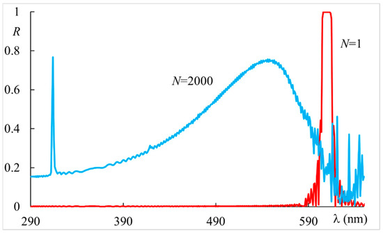
Figure 7.
Reflectivity vs. wavelength for a sample thickness , applied static field , , with material parameters indicated in the text and two different values of the light intensity: red curve , blue curve . The step index (see text).
This narrow and high reflection band is easily tuned in the near-UV range by a small variation of the applied static field, as shown in Figure 8.
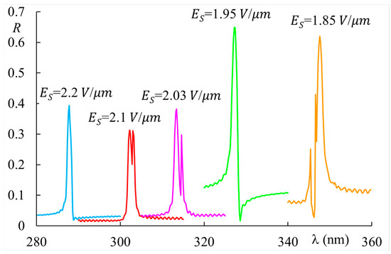
Figure 8.
Reflectivity vs. wavelength of the second-order Bragg resonance for a sample thickness , , with material parameters indicated in the text. The impinging light intensity is . The step index (see text).
Here, we show wavelength tuning in the range of a narrow peak (bandwidth ) with a reflectivity around 0.4 over a variable background. The effective tuning range can be made broader depending on the material parameters and the light absorption at short wavelengths. This result demonstrates the possibility of achieving tunable and high-selectivity filtering in the near-UV range and is quite attractive for photonic applications.
4. Conclusions
We have shown that heliconical cholesteric liquid crystals represent a new opportunity for the investigation and possible exploitation of higher-order reflections originated by the helical structure. We have demonstrated that second-order Bragg resonance with a reflectivity of 0.4–0.5 and bandwidth of is originated by the distortion of the helical structure—a consequence of optical reorientation produced by a light beam impinging at normal incidence on the sample. The variation of the applied static electric field allows for the easy tuning of the second-order reflection band in the near-UV range.
Author Contributions
Conceptualization A.H.G. and F.S.; theoretical approach F.S.; numerical calculations A.H.G.; data analysis A.H.G. and F.S.; writing—review and editing, A.H.G. and F.S. All authors have read and agreed to the published version of the manuscript.
Funding
A.H.G. acknowledge the financial support from the Russian Science Foundation (Grant No. 24-22-00283).
Data Availability Statement
The data presented in this study are available on request from the author A.H.G. due to privacy reason.
Conflicts of Interest
The authors declare no conflicts of interest.
References
- Berreman, D.W.; Scheffer, T.J. Bragg Reflection of Light from Single-Domain Cholesteric Liquid-Crystal Films. Phys. Rev. Lett. 1970, 25, 577–581. [Google Scholar] [CrossRef]
- Berreman, D.W.; Scheffer, T.J. Bragg Reflection and Transmission by Single-Domain Cholesteric Liquid-Crystal Films: Theory and Verification. Mol. Cryst. Liq. Cryst. 1970, 11, 395–405. [Google Scholar] [CrossRef]
- Blinov, L.M. Structure and Properties of Liquid Crystals; Springer: Berlin/Heidelberg, Germany, 2011. [Google Scholar]
- Blinov, L.M.; Belyaev, S.V.; Kizel, V.A. High-order reflections from a cholesteric helix induced by an electric field. Phys. Lett. 1978, A65, 33–35. [Google Scholar] [CrossRef]
- Rumi, M.; White, T.J.; Bunning, T.J. Reflection spectra of distorted cholesteric liquid crystal structure in cells with interdigitated electrodes. Opt. Exp. 2014, 22, 16510–16519. [Google Scholar] [CrossRef]
- Broer, D.J.; Mol, G.N.; van Haaren, J.A.M.M.; Lub, J. Photo-Induced Diffusion in Polymerizing Chiral-Nematic Media. Adv. Mater. 1999, 11, 573–578. [Google Scholar] [CrossRef]
- Lee, K.M.; Reshetnyak, V.Y.; McConney, M.E.; Crenshaw, E.P.; Bunning, T.J.; White, T.J.; Godman, N.P. Higher-Order Bragg Reflection Colors in Polymer-Stabilized Cholesteric Liquid Crystals. Adv. Photonics Res. 2021, 2, 2100112. [Google Scholar] [CrossRef]
- Xiang, J.; Shiyanovskii, S.V.; Imrie, C.T.; Lavrentovich, O.D. Electrooptic response of chiral nematic liquid crystals with oblique heliconical director. Phys. Rev. Lett. 2014, 112, 217801. [Google Scholar] [CrossRef]
- Xiang, J.; Li, Y.; Li, Q.; Paterson, D.A.; Storey, J.M.D.; Imrie, C.T.; Lavrentovich, O.D. Electrically tunable selective reflection of light from ultraviolet to visible and infrared by heliconical cholesterics. Adv. Mater. 2015, 27, 3014. [Google Scholar] [CrossRef]
- Mrukiewicz, M.; Iadlovska, O.S.; Babakhanova, G.; Siemianowski, S.; Shiyanovskii, S.V.; Lavrentovich, O.D. Wide temperature range of an electrically tunable selective reflection of light by oblique helicoidal cholesteric. Liq. Cryst. 2019, 46, 1544. [Google Scholar] [CrossRef]
- De Gennes, P.G. Calcul de la distorsion d’une structure cholesterique par un champ magnetique. Solid State Commun. 1968, 6, 163. [Google Scholar] [CrossRef]
- Meier, R.B. Effects of electric and magnetic fields on the structure of cholesteric liquid crystals. Appl. Phys. Lett. 1968, 12, 281. [Google Scholar] [CrossRef]
- Mrukiewicz, M.; Iadlovska, O.S.; Shiyanovskii, S.V.; Lavrentovich, O.D. Diffraction of obliquely incident light at oblique helicoidal cholesteric. In Liquid Crystals XXVI; SPIE: Bellingham, WA, USA, 2022; Volume 12207, pp. 63–68. [Google Scholar]
- Iadlovska, O.S.; Thapa, K.; Rajabi, M.; Mrukiewicz, M.; Shiyanovskii, S.V.; Lavrentovich, O.D. Electrically tunable total reflection of light by oblique helicoidal cholesteric. MRS Bull. 2024, 49, 835–850. [Google Scholar] [CrossRef]
- Nava, G.; Ciciulla, F.; Iadlovska, O.S.; Lavrentovich, O.D.; Simoni, F.; Lucchetti, L. Pitch tuning induced by optical torque in heliconical cholesteric liquid crystals. Phys. Rev. Res. 2019, 1, 033215. [Google Scholar] [CrossRef]
- Simoni, F. Nonlinear optical propagation near the Bragg resonance in heliconical cholesteric liquid crystals. Opt. Lett. 2020, 45, 6510. [Google Scholar] [CrossRef]
- Gevorgyan, A.H.; Simoni, F. Onset of Optical Instabilities in the Nonlinear Optical Transmission of Heliconical Cholesteric Liquid Crystals. Photonics 2022, 9, 139–148. [Google Scholar] [CrossRef]
- Gevorgyan, A.H.; Simoni, F. Nonlinear Optical Propagation in Heliconical Cholesteric Liquid Crystals. Nov. Opt. Mater. 2024, 4, 93–119. [Google Scholar]
- Gevorgyan, A.H.; Simoni, F. Light-induced Self-oscillations and Spoiling of the Bragg Resonance due to Nonlinear Optical Propagation in Heliconical Cholesteric Liquid Crystals. Photonics 2022, 9, 881–892. [Google Scholar] [CrossRef]
- Mrukiewicz, M.; Cigl, M.; Perkowski, P.; Karcz, J.; Hamplova, V.; Bubnov, A. Dual tunability of selective reflection by light and electric field for self-organizing materials. J. Mol. Liq. 2024, 400, 124540. [Google Scholar] [CrossRef]
- Gevorgyan, A.H.; Harutyunyan, M.Z. Chiral photonic crystals with an anisotropic defect layer. Phys. Rev. E 2007, 76, 031701-9. [Google Scholar] [CrossRef]
- Wu, S.-T.; Ramos, E.; Finkenzeller, U. Polarized UV spectroscopy of conjugated liquid crystals. J. Appl. Phys. 1990, 78, 85. [Google Scholar] [CrossRef]
- Lin, P.-T.; Wu, S.-T.; Chang, C.-Y.; Hsu, C.-S. UV Stability of High Birefringence Liquid Crystals. Mol. Cryst. Liq. Cryst. 2004, 411, 243–253. [Google Scholar] [CrossRef]
Disclaimer/Publisher’s Note: The statements, opinions and data contained in all publications are solely those of the individual author(s) and contributor(s) and not of MDPI and/or the editor(s). MDPI and/or the editor(s) disclaim responsibility for any injury to people or property resulting from any ideas, methods, instructions or products referred to in the content. |
© 2025 by the authors. Licensee MDPI, Basel, Switzerland. This article is an open access article distributed under the terms and conditions of the Creative Commons Attribution (CC BY) license (https://creativecommons.org/licenses/by/4.0/).