

Hydrogen Reduction of Tellurium Oxide in a Rotary Kiln, Initial Approaches for a Sustainable Process


Abstract
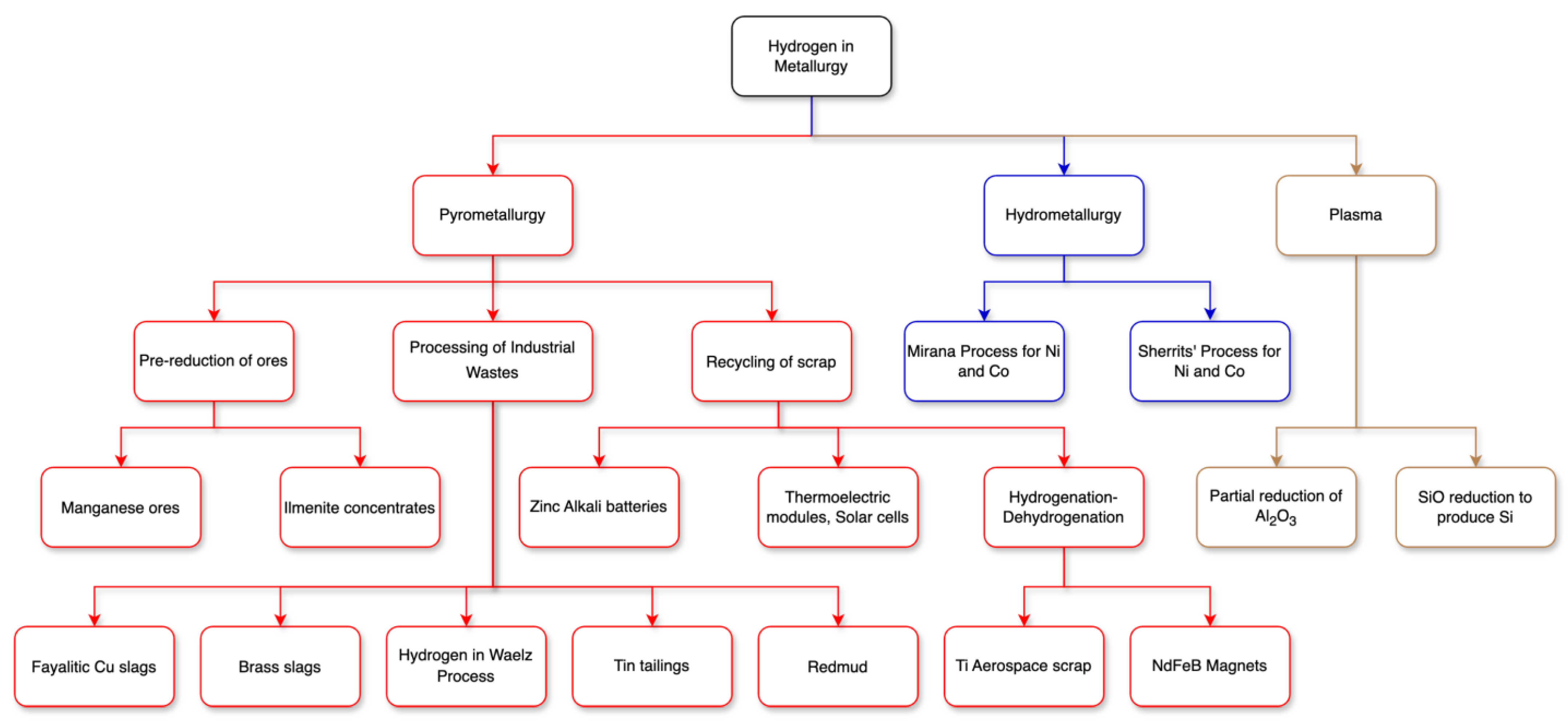
1. Introduction
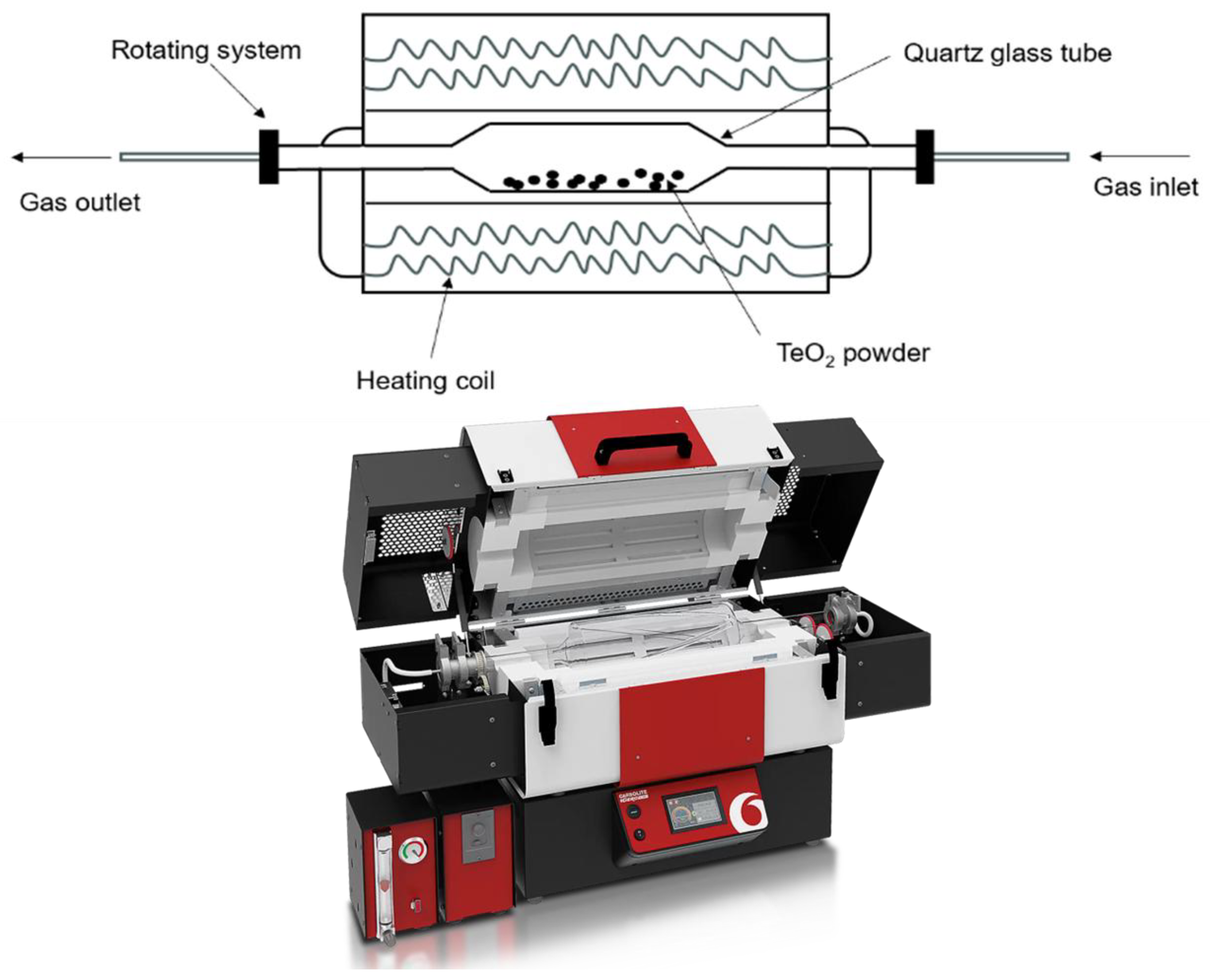
2. Materials and Methods
3. Results and Discussion
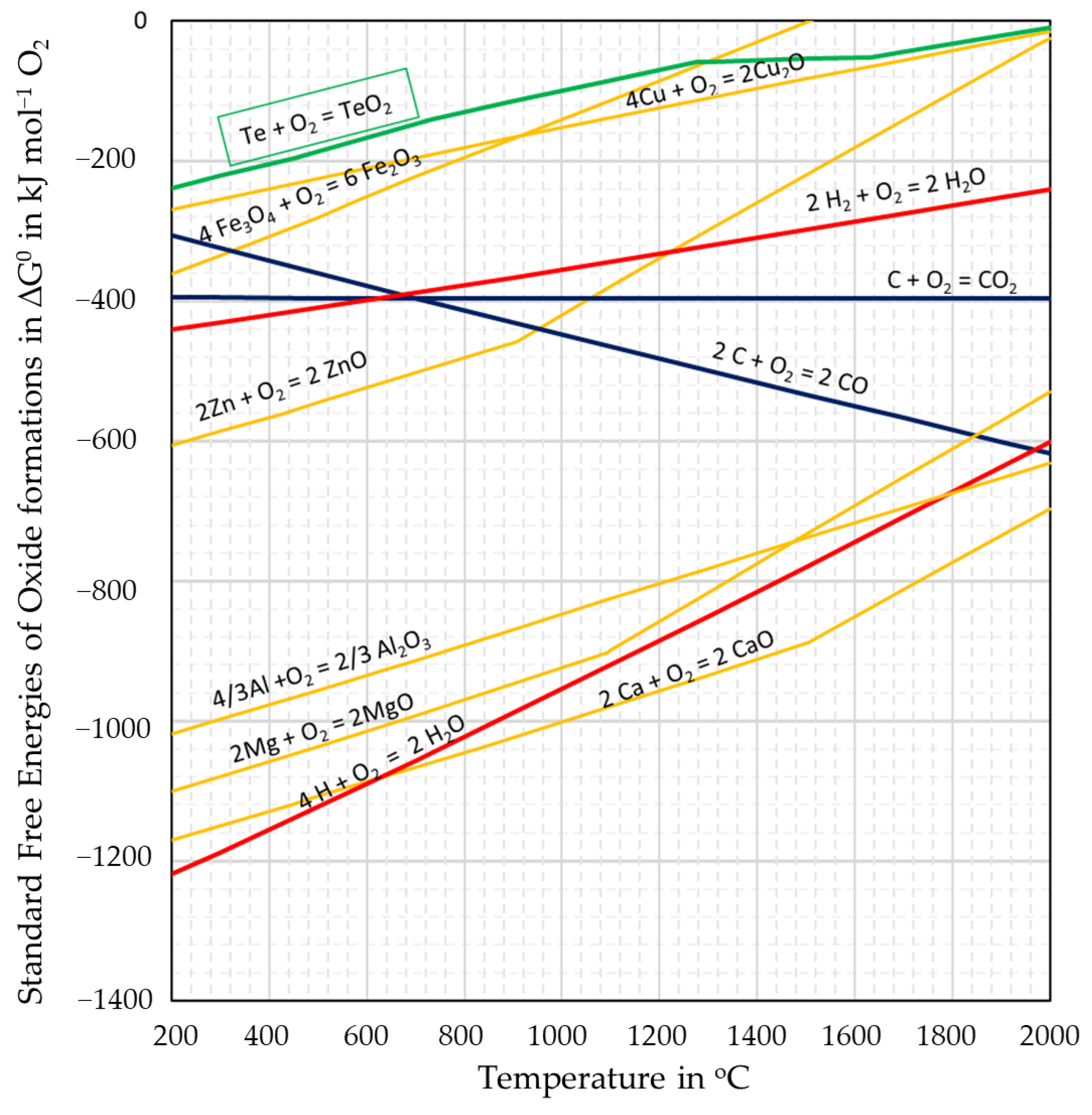
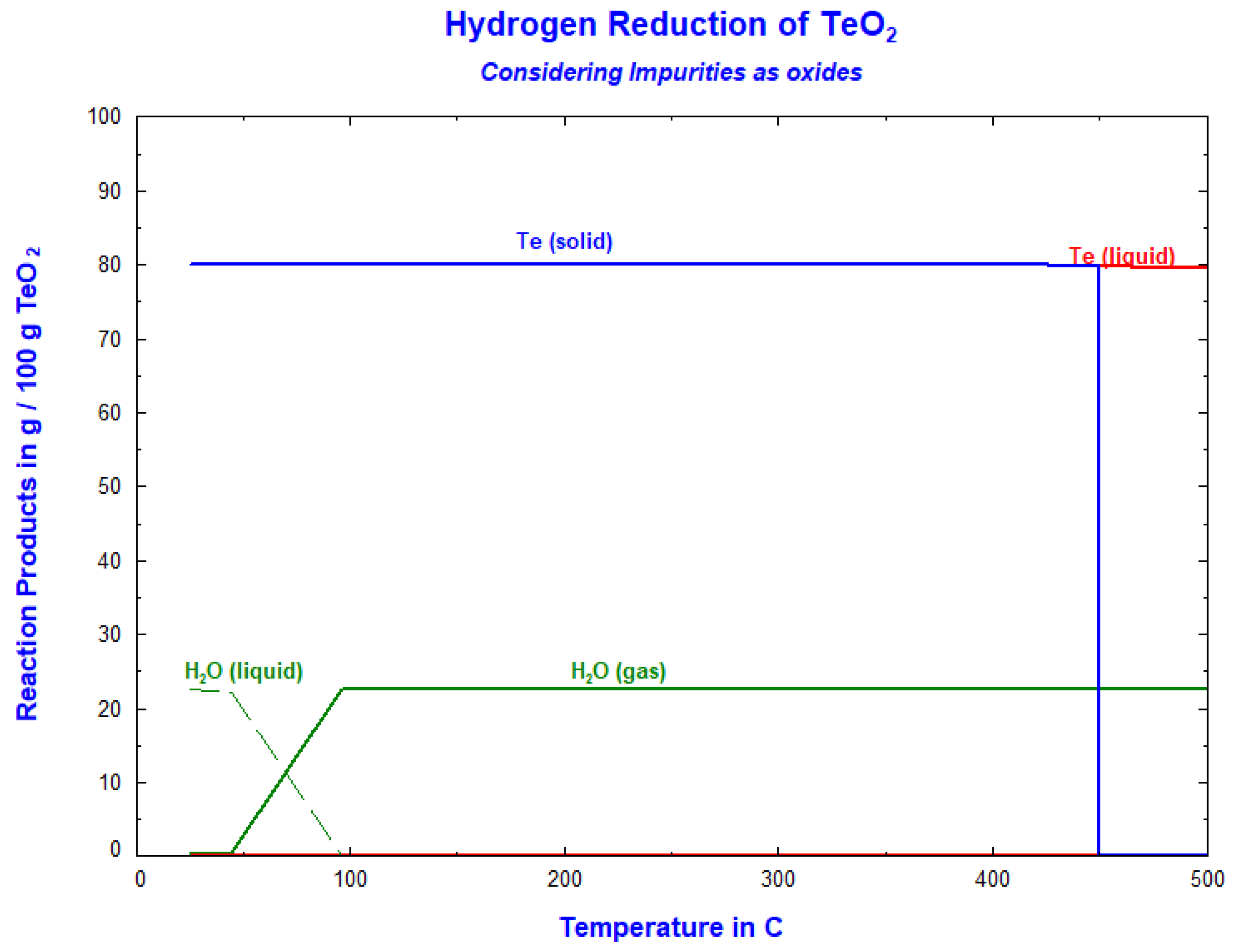
3.1. Thermodynamic Calculations Using FactSage 8.0
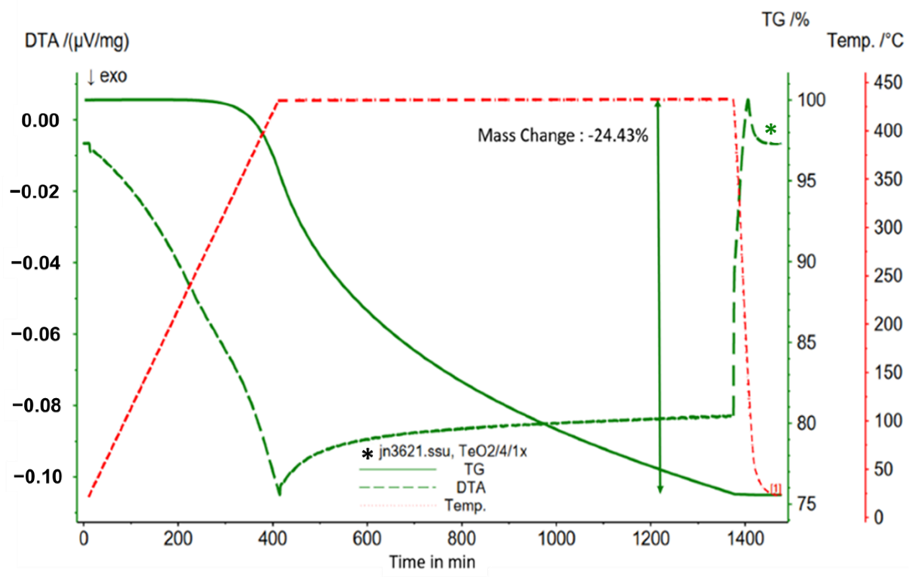
3.2. Differential Thermal Analysis and Thermo-Gravimetric Analysis
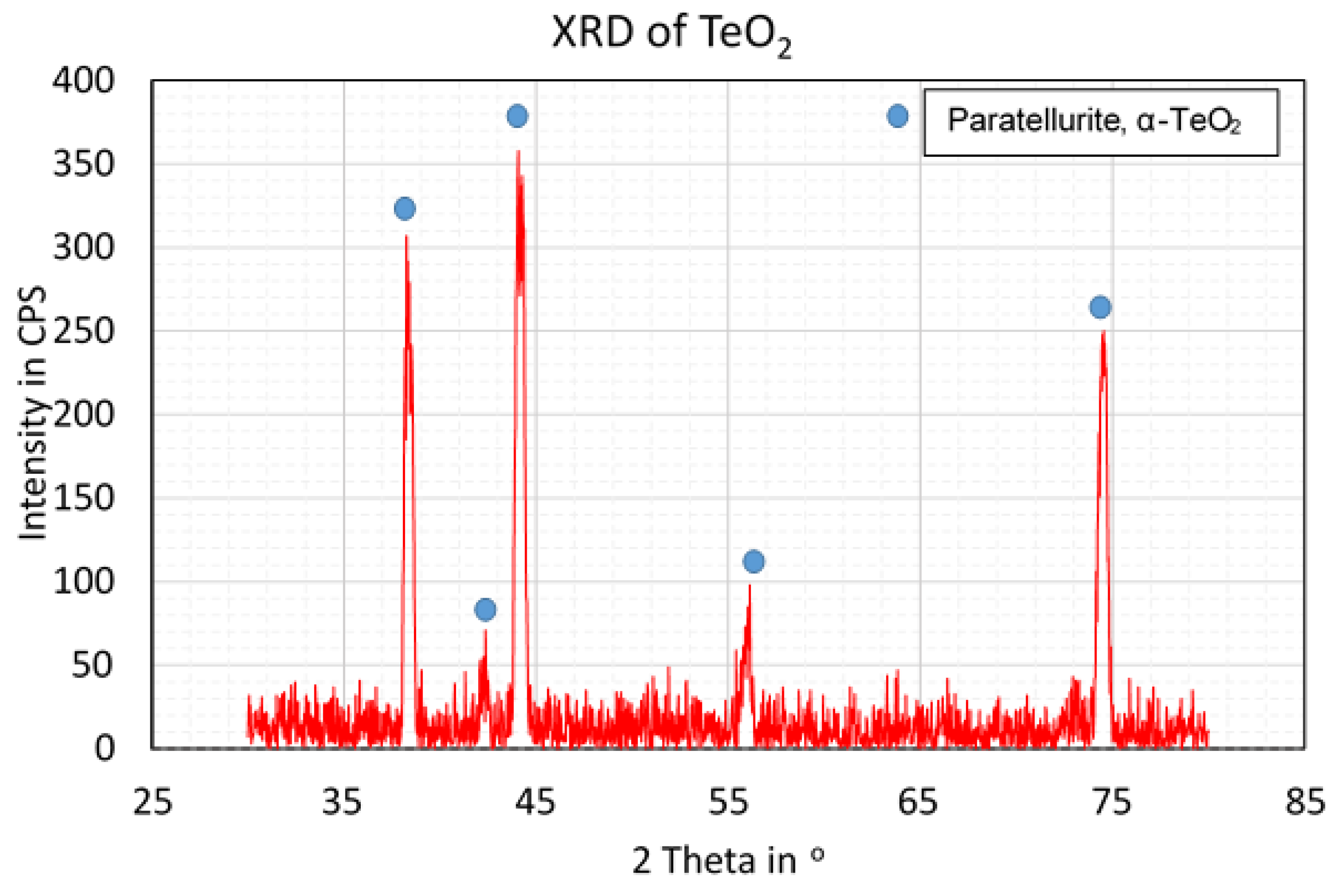
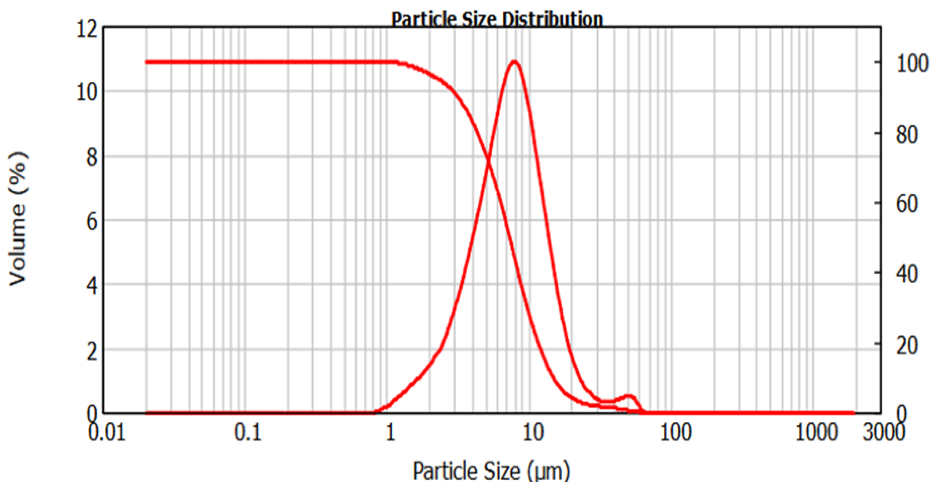
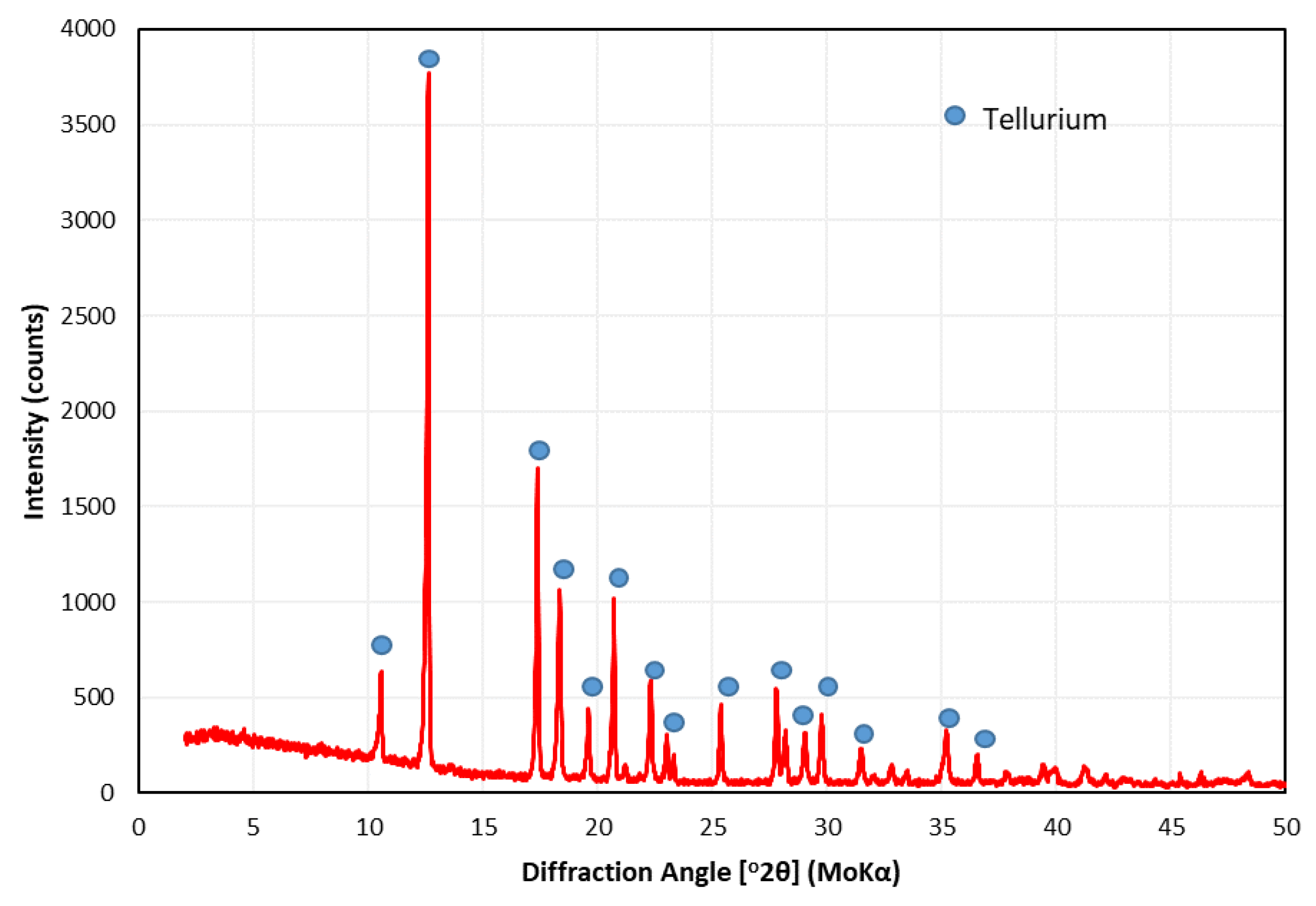
3.3. Materials Characterisation
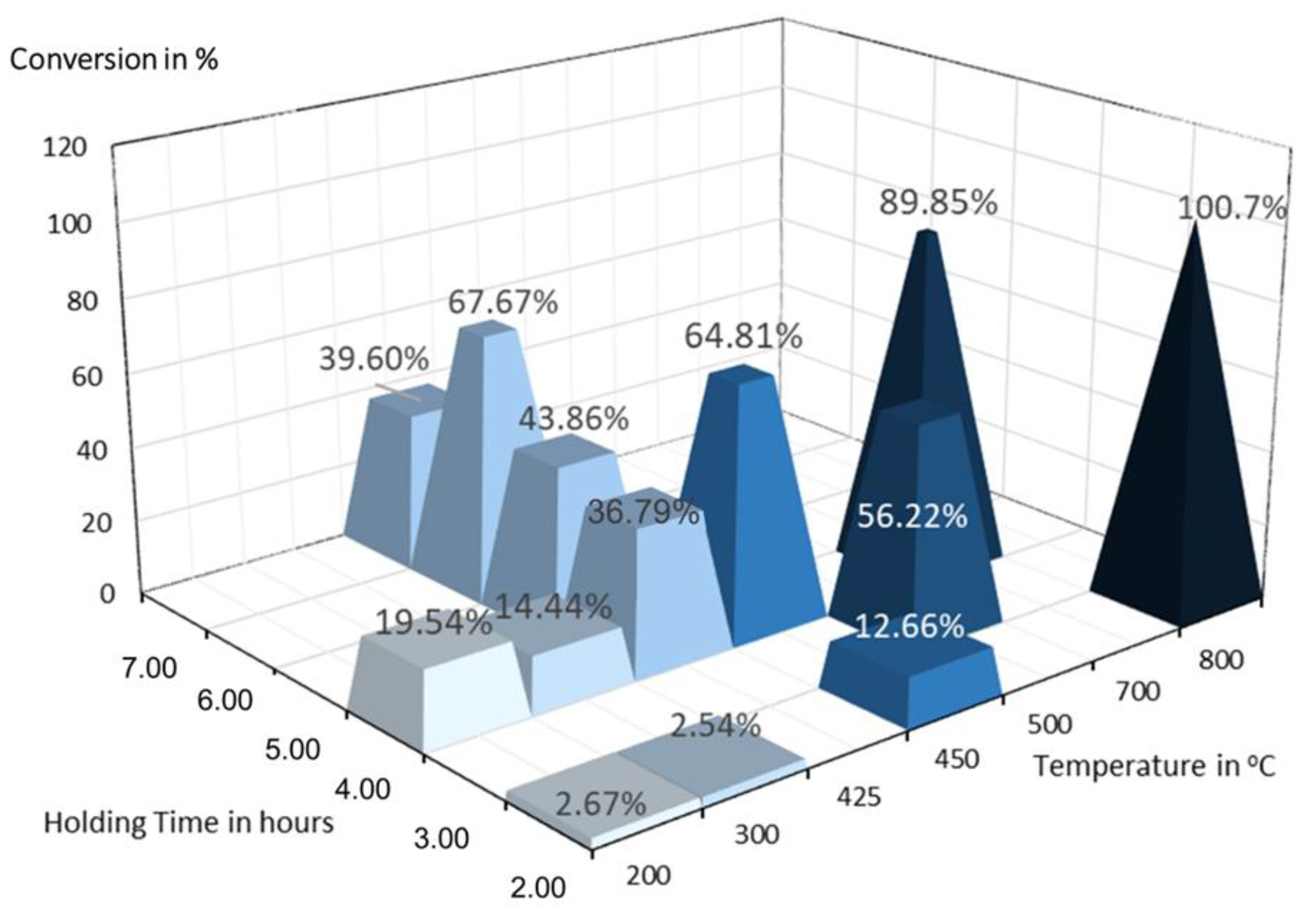
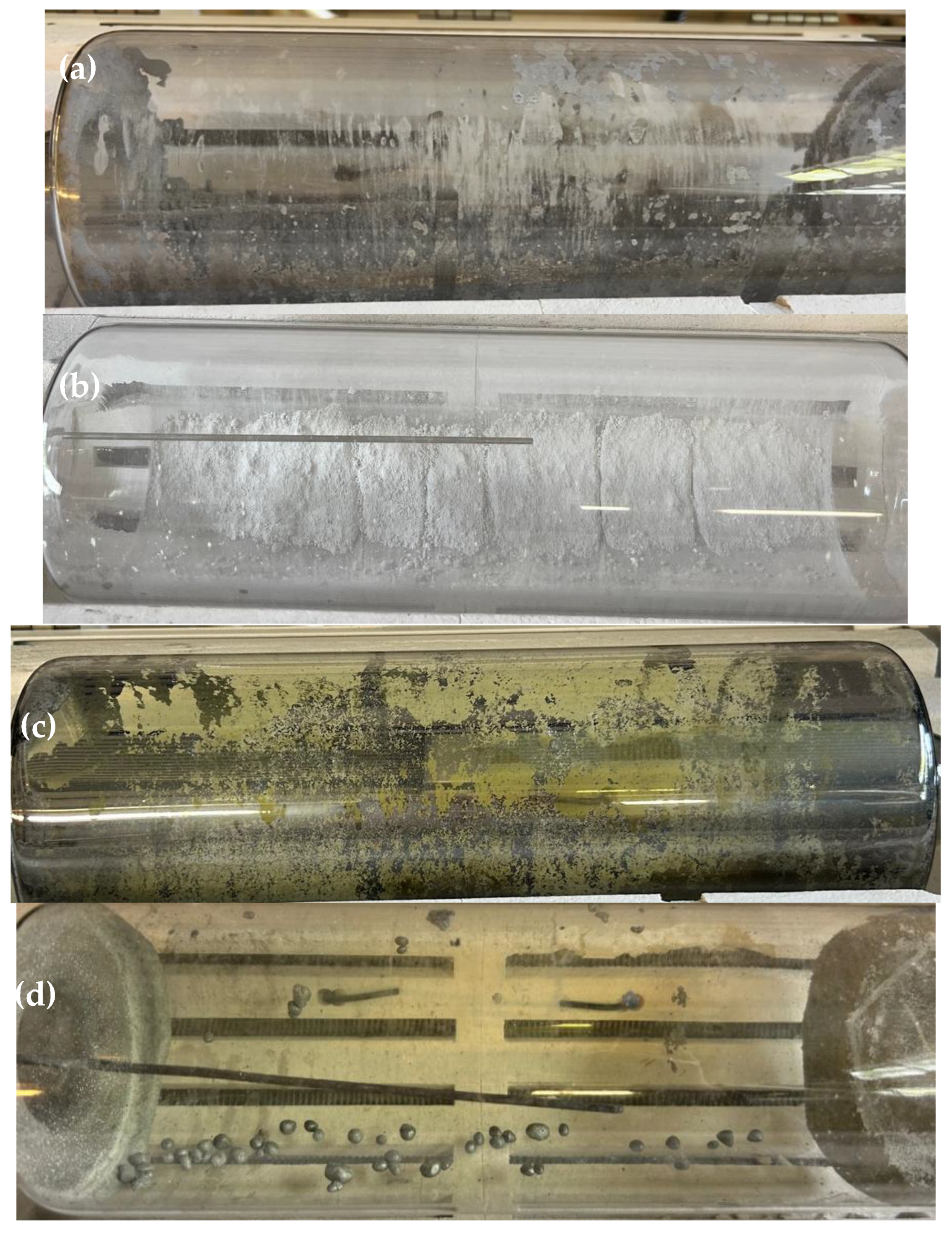
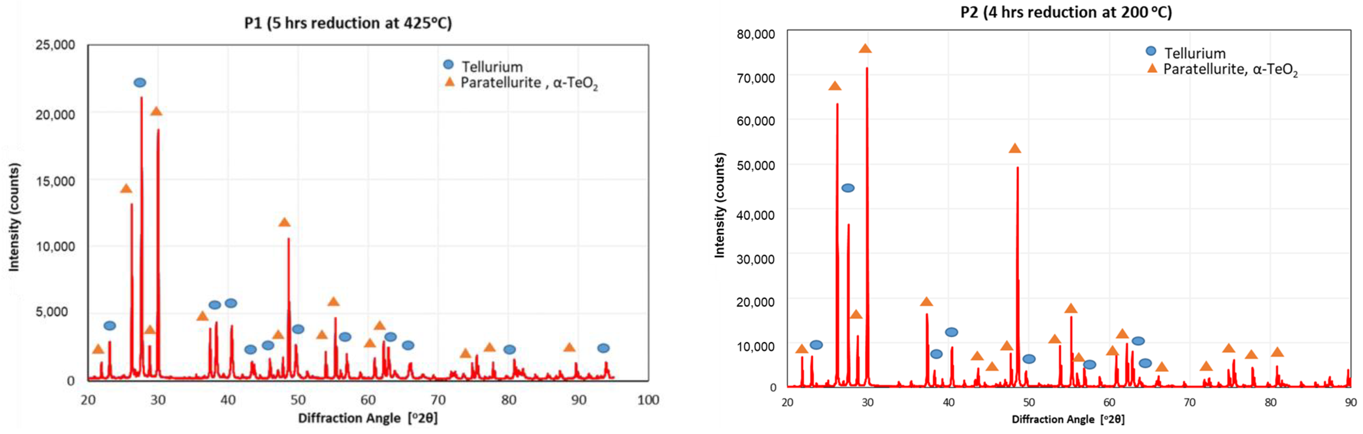
3.4. Reduction of TeO2
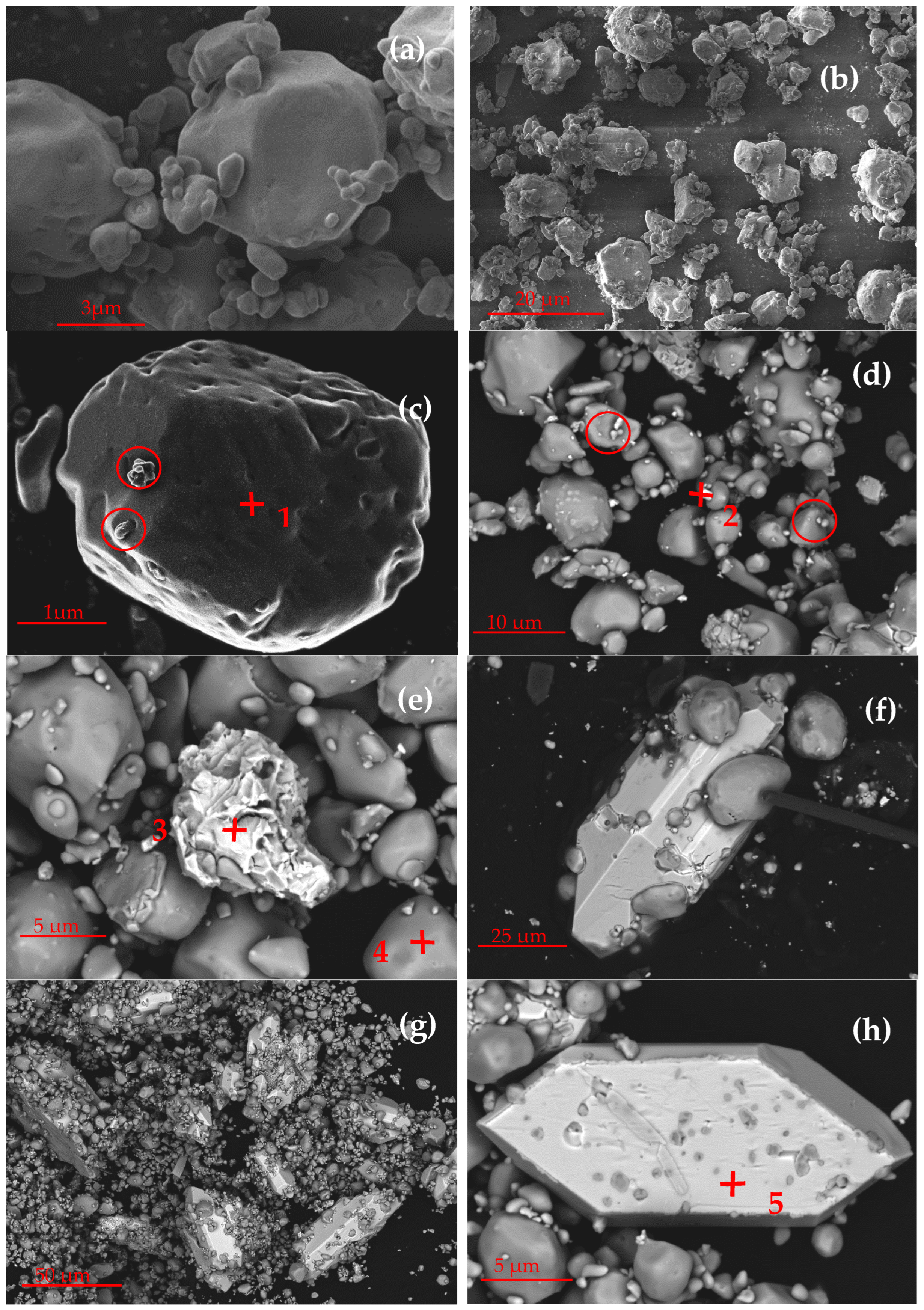
3.5. Microscopic Analysis
4. Conclusions
Author Contributions
Funding
Data Availability Statement
Conflicts of Interest
References
- Zhang, H.; Li, Z.; Yang, Y.; Zha, G.; Xu, B.; Liu, D.; Yang, B.; Jiang, W. Advances in tellurium recovery and purification: A comprehensive review of separation methods and emerging technologies. Resour. Conserv. Recycl. 2025, 215, 108160. [Google Scholar] [CrossRef]
- Zhu, Y.; Jin, Y.; Zhu, J.; Dong, X.; Liu, M.; Sun, Y.; Guo, M.; Li, F.; Guo, F.; Zhang, Q.; et al. Design of N-Type Textured Bi2Te3 with Robust Mechanical Properties for Thermoelectric Micro-Refrigeration Application. Adv. Sci. 2022, 10, 2206395. [Google Scholar] [CrossRef] [PubMed]
- Habashi, F. Precious Metals, Refractory Metals, Scattered Metals, Radioactive Metals and Rare Earth Metals. In Handbook of Extractive Metallurgy; Wiley: Hoboken, NJ, USA, 1997; Volume 3, pp. 1649–1684. [Google Scholar]
- Habashi, F. Handbook of Extractive Metallurgy Volume 2; Métallurgie Extractive Québec: Québec City, Québec, Canada, 1997. [Google Scholar]
- Makuei, F.M.; Senanayake, G. Extraction of tellurium from lead and copper bearing feed materials and interim metallurgical products—A short review. Miner. Eng. 2018, 115, 79–87. [Google Scholar] [CrossRef]
- Chung, H.; Friedrich, S.; Becker, J.; Friedrich, B. Purification principles and methodologies to produce high-purity tellurium. Can. Met. Q. 2024, 63, 1626–1642. [Google Scholar] [CrossRef]
- Rix, A.J.; Steyl, J.D.T.; Rudman, J.; Terblanche, U.; van Niekerk, J.L. First Solar’s CdTe Module Technology—Performance, Life Cycle, Health and Safety Impact Assessment; Version: Final-Rev A.; Centre for renewable and sustainable energy studies: Stellenbosch, South Africa, 2015; pp. 1–32. [Google Scholar]
- Fraunhofer IWKS Recycling and Long-Term Stability of Thermoelectric and Magnetocaloric Systems (RecycleTEAM). Available online: https://www.recycleteam.de/en.html (accessed on 13 August 2024).
- Zhang, X.; Xu, W.; Wang, S.; Liu, D.; Deng, P.; Deng, J.; Jiang, W. Research status of recovery of tellurium from cadmium telluride photovoltaic modules. IOP Conf. Ser. Mater. Sci. Eng. 2020, 782, 022024. [Google Scholar] [CrossRef]
- Anderson, C.D. Hydrometallurgical recovery of tellurium dioxide from cadmium telluride photovoltaic manufacturing scrap. Mining, Met. Explor. 2012, 29, 133–134. [Google Scholar] [CrossRef]
- Fthenakis, V.M.; Wang, W. Extraction and separation of Cd and Te from cadmium telluride photovoltaic manufacturing scrap. Prog. Photovoltaics: Res. Appl. 2006, 14, 363–371. [Google Scholar] [CrossRef]
- Fthenakis, V.; Duby, P.; Wenming, W.; Graves, C.; Belova, A. Recycling of CdTe Photovoltaic Modules : Recovery of Cadmium and Tellurium. In Proceedings of the 21st European Photovoltaic Solar Energy Conference, Dresden, Germany, 4–7 September 2006; pp. 2539–2541. [Google Scholar]
- Greenwood, N.; Earnshaw, A. Chemistry of the Elements, 2nd ed.; Butterworth-Heinemann: Oxford, UK, 1997. [Google Scholar]
- Li, Z.; Liu, D.; Zha, G.; Jiang, W.; Huang, D.; Xu, B.; Yang, B. Efficient separation and recovery of tellurium and copper from high-value-added industrial copper telluride slag by a sustainable process. J. Sustain. Met. 2023, 9, 738–752. [Google Scholar] [CrossRef]
- The European Green Deal—European Commission. Available online: https://commission.europa.eu/strategy-and-policy/priorities-2019-2024/european-green-deal_en (accessed on 23 July 2024).
- Cavaliere, P. Hydrogen in Reduction Processes. In Hydrogen Assisted Direct Reduction of Iron Oxides; Springer International Publishing: Cham, Switzerland, 2022; pp. 47–75. [Google Scholar]
- Hassan, Q.; Sameen, A.Z.; Salman, H.M.; Jaszczur, M.; Al-Jiboory, A.K. Hydrogen energy future: Advancements in storage technologies and implications for sustainability. J. Energy Storage 2023, 72, 108404. [Google Scholar] [CrossRef]
- Rukini, A.; Rhamdhani, M.A.; Brooks, G.A.; Van den Bulck, A. Metals Production and Metal Oxides Reduction Using Hydrogen: A Review. J. Sustain. Met. 2022, 8, 1–24. [Google Scholar] [CrossRef]
- Gupta, R.; Kumar, V.A.; Khanra, G. Reactive and liquid-phase sintering techniques. In Intermetallic Matrix Composites; Elsevier: Amsterdam, The Netherlands, 2018; pp. 303–318. [Google Scholar] [CrossRef]
- Yue, M.; Lambert, H.; Pahon, E.; Roche, R.; Jemei, S.; Hissel, D. Hydrogen energy systems: A critical review of technologies, applications, trends and challenges. Renew. Sustain. Energy Rev. 2021, 146, 111180. [Google Scholar] [CrossRef]
- Ishaq, H.; Dincer, I.; Crawford, C. A review on hydrogen production and utilization: Challenges and opportunities. Int. J. Hydrogen Energy 2022, 47, 26238–26264. [Google Scholar] [CrossRef]
- Birich, A.; Marepalli, K.; Wegmann, F.; Chung, H.; Friedrich, B. Anwendungspotentiale von Wasserstoff in der Nichteisen-Metallurgie (Application of Hydrogen in the Non-Ferrous Metallurgy). Erzmetall- World Metall. 2024, 77, 192–203. [Google Scholar]
- Altmannshofer, S.; Eisele, I.; Gschwandtner, A. Hydrogen microwave plasma treatment of Si and SiO2. Surf. Coatings Technol. 2016, 304, 359–363. [Google Scholar] [CrossRef]
- Li, Z.Y.; Yu, K.; Gao, Y.; Liu, J.; Jin, D.; Zhai, Y.C. Effect of Particle Size on Hydrogen Reduction Reaction Kinetics Parameters of Cu2O Powders. Mater. Sci. Forum 2011, 694, 769–772. [Google Scholar] [CrossRef]
- Hidayat, T.; Rhamdhani, M.; Jak, E.; Hayes, P. The Kinetics of Reduction of Dense Synthetic Nickel Oxide in H2-N2 and H2-H2O Atmospheres. Met. Mater. Trans. B 2009, 40, 1–16. [Google Scholar] [CrossRef]
- Dang, J.; Zhang, G.-H.; Chou, K.-C.; Reddy, R.G.; He, Y.; Sun, Y. Kinetics and mechanism of hydrogen reduction of MoO3 to MoO2. Int. J. Refract. Met. Hard Mater. 2013, 41, 216–223. [Google Scholar] [CrossRef]
- Keilholz, S.; Paul, R.; Dorsch, L.Y.; Kohlmann, H. In Situ X-ray Diffraction Studies on the Reduction of V2O5 and WO3 by Using Hydrogen. Chem. A Eur. J. 2023, 29, e202203932. [Google Scholar] [CrossRef]
- Altay, M.C.; Eroglu, S. H2-mediated reduction of GeO2 and chemical vapor deposition of polycrystalline Ge porous films. Thin Solid Films 2023, 783, 140049. [Google Scholar] [CrossRef]
- Trawiński, B.; Bochentyn, B.; Kusz, B. A study of a reduction of a micro- and nanometric bismuth oxide in hydrogen atmosphere. Thermochim. Acta 2018, 669, 99–108. [Google Scholar] [CrossRef]
- Kim, B.-S.; Lee, J.-C.; Yoon, H.-S.; Kim, S.-K. Reduction of SnO2 with Hydrogen. Mater. Trans. 2011, 52, 1814–1817. [Google Scholar] [CrossRef]
- Hovestadt, G.; Coldewe, M.; Friedrich, B. Determining critical parameters of hydrogen reduction treatment of low copper-containing primary slags. In Proceedings of the European Metallurgical Conference 2023, Düsseldorf, Germany, 11–14 June 2023; pp. 1–7. [Google Scholar] [CrossRef]
- Kar, M.K.; van der Eijk, C.; Safarian, J. Kinetics Study on the Hydrogen Reduction of Bauxite Residue-Calcite Sintered Pellets at Elevated Temperature. Metals 2023, 13, 644. [Google Scholar] [CrossRef]
- Qu, G.; Wei, Y.; Li, B.; Wang, H.; Yang, Y.; McLean, A. Distribution of copper and iron components with hydrogen reduction of copper slag. J. Alloys Compd. 2020, 824, 153910. [Google Scholar] [CrossRef]
- Tang, J.; Chu, M.-S.; Li, F.; Feng, C.; Liu, Z.-G.; Zhou, Y.-S. Development and progress on hydrogen metallurgy. Int. J. Miner. Met. Mater. 2020, 27, 713–723. [Google Scholar] [CrossRef]
- Luidold, S.; Antrekowitsch, H. Hydrogen as a reducing agent: State-of-the-art science and technology. JOM 2007, 59, 20–26. [Google Scholar] [CrossRef]
- Trawiński, B.; Bochentyn, B.; Łapiński, M.; Kusz, B. A study of the kinetics of bismuth telluride synthesis by an oxide reduction method. Thermochim. Acta 2020, 683, 178437. [Google Scholar] [CrossRef]
- Trawiński, B.; Kusz, B. Kinetic analysis of the reduction of a ternary system of Bi, Sb and Te oxides by hydrogen for BiSbTe3 synthesis. Thermochim. Acta 2021, 701, 178966. [Google Scholar] [CrossRef]
- Peray, K.E. The Rotary Cement Kiln, 2nd ed.; Arnold: London, UK, 1986. [Google Scholar]
- Boateng, A.A. Rotary Kilns: Transport Phenomena and Transport Processes; Elsevier: Amsterdam, The Netherlands, 2016. [Google Scholar]
- Avrami, M. Kinetics of Phase Change. II Transformation-Time Relations for Random Distribution of Nuclei. J. Chem. Phys. 1940, 8, 212–224. [Google Scholar] [CrossRef]
- Pöyhtäri, S.; Ruokoja, J.; Heikkinen, E.-P.; Heikkilä, A.; Kokkonen, T.; Tynjälä, P. Kinetic Analysis of Hydrogen Reduction of Nickel Compounds. Met. Mater. Trans. B 2023, 55, 251–265. [Google Scholar] [CrossRef]


| Test | Temperature [°C] | Holding Time [h] |
|---|---|---|
| 1 | 200 | 2 |
| 2 | 200 | 4 |
| 3 | 300 | 2 |
| 4 | 300 | 4 |
| 5 | 425 | 4 |
| 6 | 425 | 5 |
| 7 | 425 | 6 |
| 8 | 425 | 7 |
| 9 | 450 | 4 |
| 10 | 500 | 2 |
| 11 | 500 | 3 |
| 12 | 700 | 4 |
| 13 | 800 | 2 |
| Ag | Al | Ca | Fe | Mg | Na | Si | Cu | Se | Pb | Bi |
|---|---|---|---|---|---|---|---|---|---|---|
| 0.18 | 0.35 | 6.55 | 0.90 | 0.15 | 3.25 | 21.85 | 6.25 | 6.25 | 6.25 | 8.75 |
| Sample | Conversion by Mass Balance | Theoretical Temetallic | Phase Composition by XRD | |
|---|---|---|---|---|
| Te | TeO2 | |||
| P1 | 43.09% | 37.57% | 43.5% | 56.5% |
| P2 | 19.54% | 16.17% | 18.1% | 81.9% |
Disclaimer/Publisher’s Note: The statements, opinions and data contained in all publications are solely those of the individual author(s) and contributor(s) and not of MDPI and/or the editor(s). MDPI and/or the editor(s) disclaim responsibility for any injury to people or property resulting from any ideas, methods, instructions or products referred to in the content. |
© 2025 by the authors. Licensee MDPI, Basel, Switzerland. This article is an open access article distributed under the terms and conditions of the Creative Commons Attribution (CC BY) license (https://creativecommons.org/licenses/by/4.0/).
Share and Cite
Chung, H.; Friedrich, S.; Qu, M.; Friedrich, B. Hydrogen Reduction of Tellurium Oxide in a Rotary Kiln, Initial Approaches for a Sustainable Process. Crystals 2025, 15, 478. https://doi.org/10.3390/cryst15050478
Chung H, Friedrich S, Qu M, Friedrich B. Hydrogen Reduction of Tellurium Oxide in a Rotary Kiln, Initial Approaches for a Sustainable Process. Crystals. 2025; 15(5):478. https://doi.org/10.3390/cryst15050478
Chicago/Turabian StyleChung, Hanwen, Semiramis Friedrich, Mengqi Qu, and Bernd Friedrich. 2025. "Hydrogen Reduction of Tellurium Oxide in a Rotary Kiln, Initial Approaches for a Sustainable Process" Crystals 15, no. 5: 478. https://doi.org/10.3390/cryst15050478
APA StyleChung, H., Friedrich, S., Qu, M., & Friedrich, B. (2025). Hydrogen Reduction of Tellurium Oxide in a Rotary Kiln, Initial Approaches for a Sustainable Process. Crystals, 15(5), 478. https://doi.org/10.3390/cryst15050478