

Orientation-Dependent Nanomechanical Behavior of Pentaerythritol Tetranitrate as Probed by Multiple Nanoindentation Tip Geometries

 , , , , and
Abstract
1. Introduction
2. Materials and Methods
3. Results
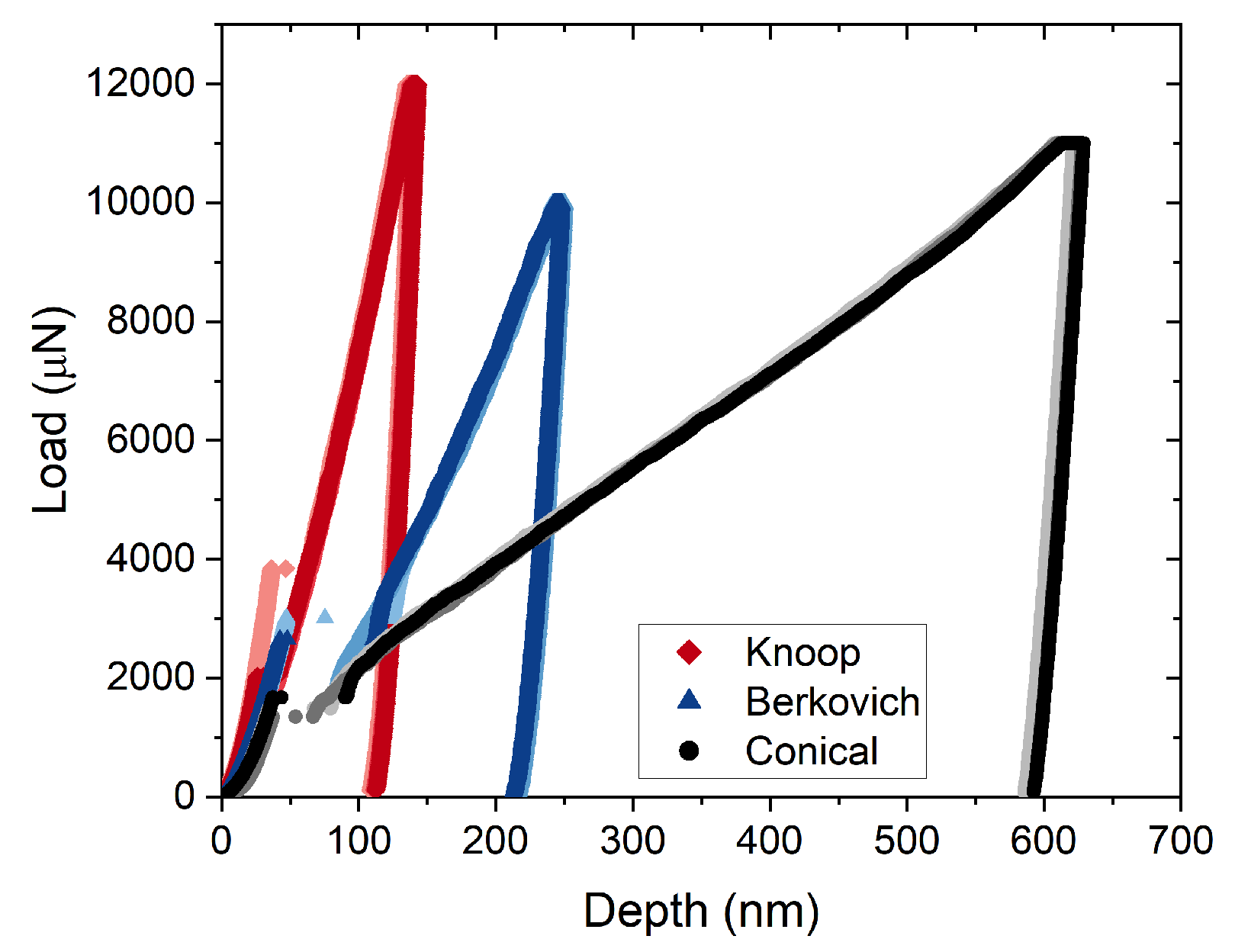
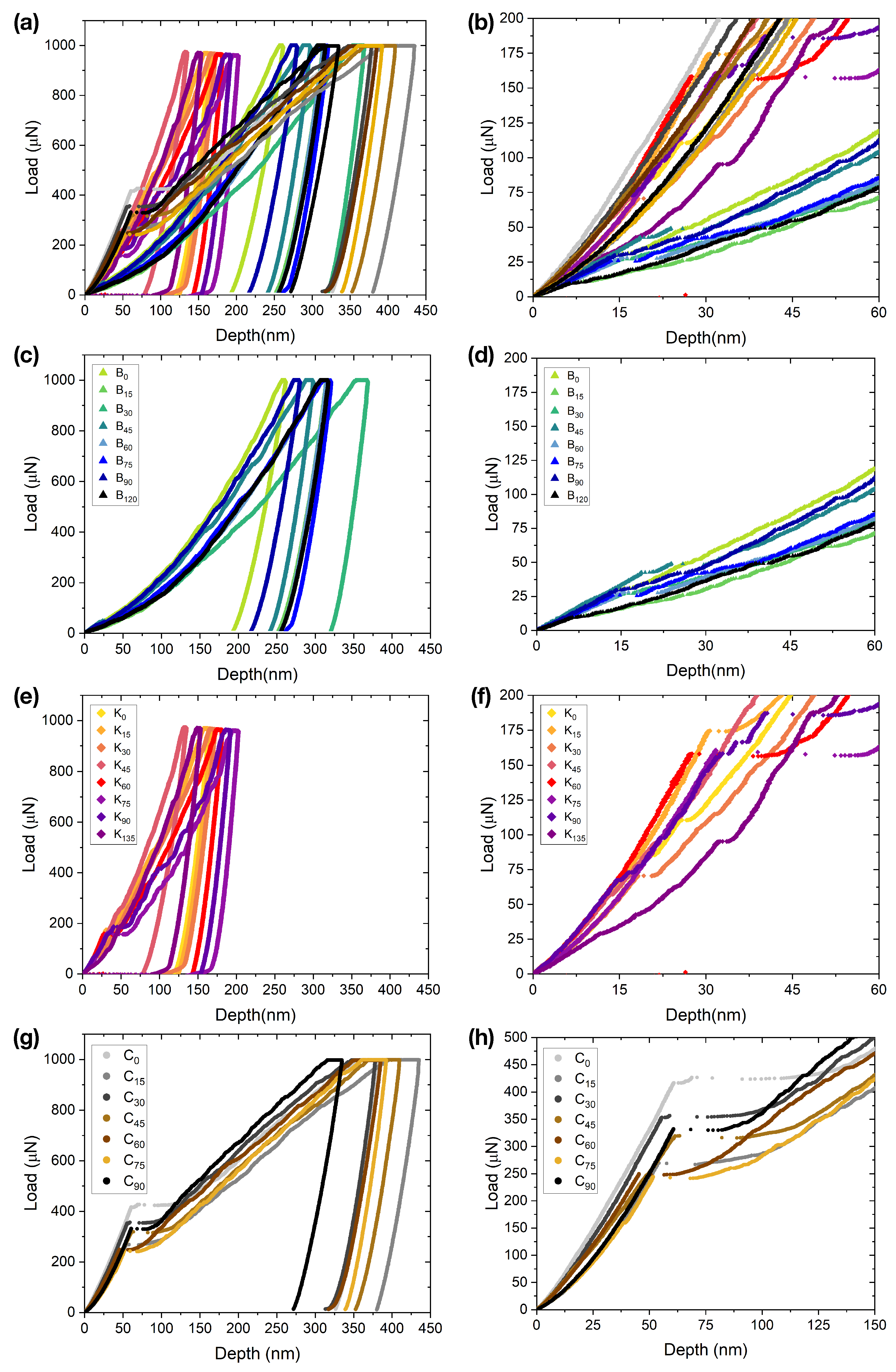
3.1. Yield Behavior
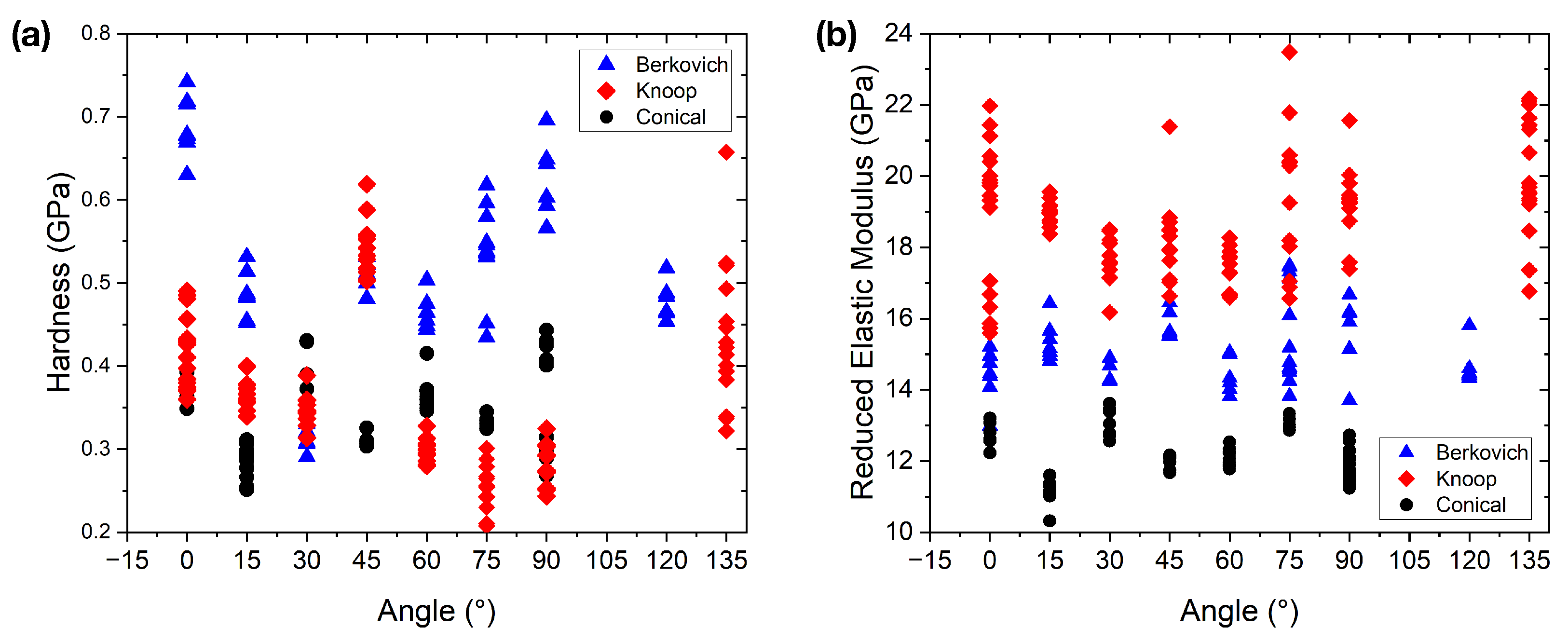
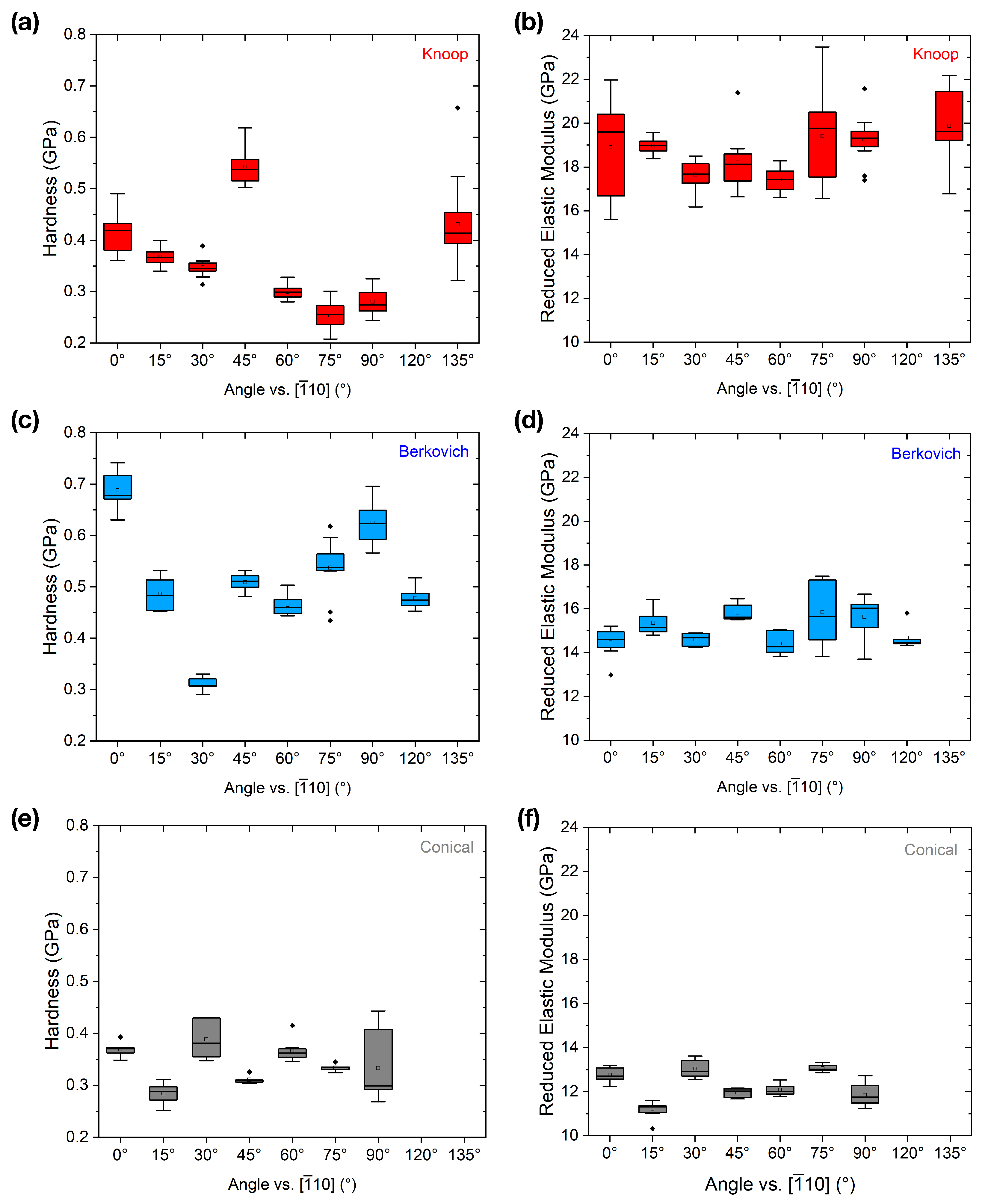
3.2. Hardness and Reduced Elastic Modulus
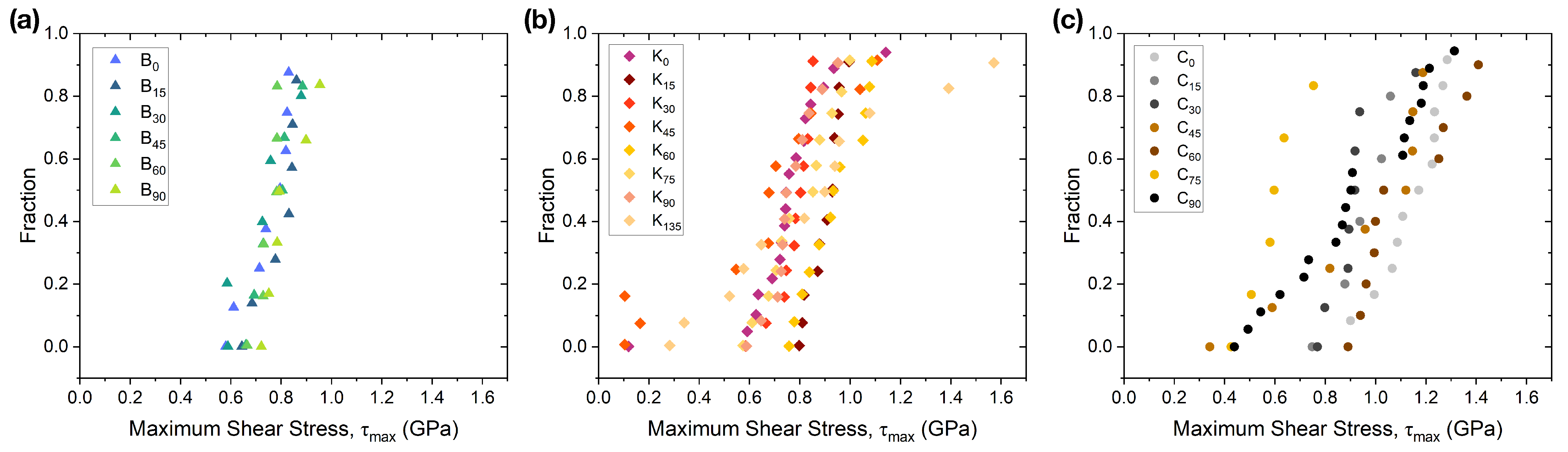
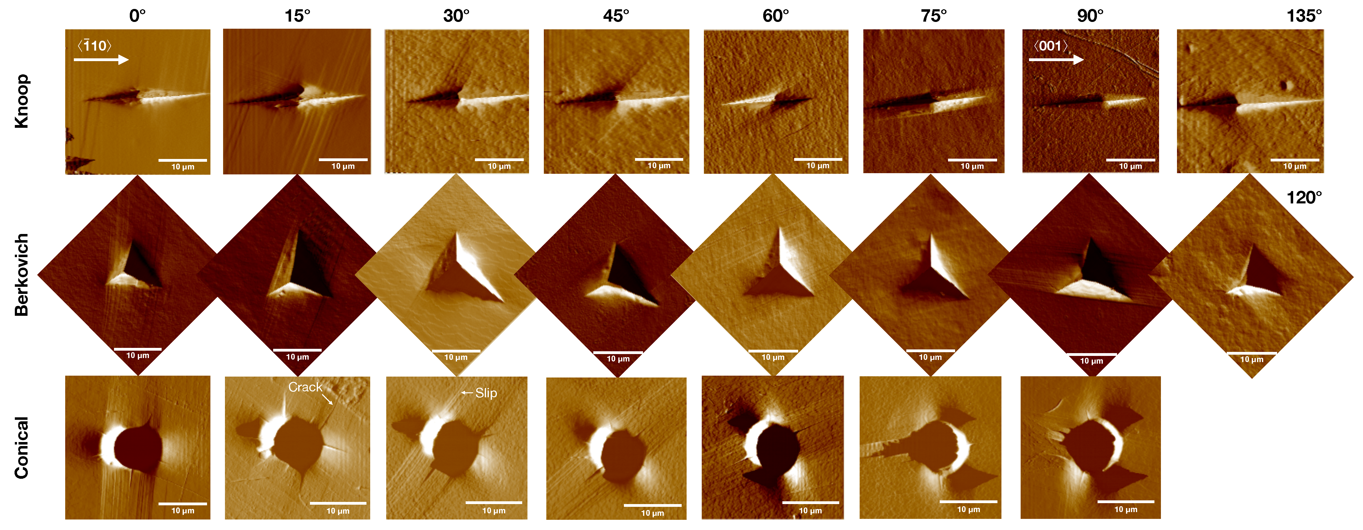
3.3. Slip Behavior and Fracture Initiation
4. Discussion
5. Conclusions
Author Contributions
Funding
Data Availability Statement
Acknowledgments
Conflicts of Interest
Appendix A

References
- Wang, K.; Mishra, M.; Sun, C. Exceptionally Elastic Single-Component Pharmaceutical Crystals. Chem. Mater. 2019, 31, 1794–1799. [Google Scholar] [CrossRef]
- Joiris, E.; di Martino, P.; Berneron, C.; Guyot-Hermann, A.M.; Guyot, J.C. Compression Behavior of Orthorhombic Paracetamol. Pharm. Res. 1998, 15, 1122–1130. [Google Scholar] [CrossRef] [PubMed]
- Majumder, S.; Xiang, T.; Sun, C.; Mara, N. Crystal Structure-Mechanical Property Relationship in Succinic Acid and L-alanine Probed by Nanoindentation. Int. J. Pharm. 2024, 665, 1247160. [Google Scholar] [CrossRef] [PubMed]
- Datta, S.; Grant, D. Crystal Structures of Drugs: Advances in Determination, Prediction and Engineering. Nat. Rev. Drug Discov. 2004, 3, 42–57. [Google Scholar] [CrossRef]
- Hamilton, B.; Kroonblawd, M.; Strachan, A. The Potential Energy Hotspot: Effects of Impact Velocity, Defect Geometry, and Crystallographic Orientation. J. Phys. Chem. C 2022, 126, 3743–3755. [Google Scholar] [CrossRef]
- Yarrington, C.; Wixom, R.; Damm, D. Shock Interactions with Heterogeneous Energetic Materials. J. Appl. Phys. 2018, 123, 105901. [Google Scholar] [CrossRef]
- Olenik, B.; Keil, B.; Jeschke, P. Importance of Chemical Polymorphism in Modern Crop Protection. Pest Manag. Sci. 2022, 78, 2746–2758. [Google Scholar] [CrossRef]
- Honer, K.; Kalfaoglu, E.; Pico, C.; McCann, J.; Baltrusaitis, J. Mechanosynthesis of Magnesium and Calcium Salt-Urea Ionic Cocrystal Fertilizer Materials for Improved Nitrogen Management. ACS Sustain. Chem. Eng. 2017, 5, 8546–8550. [Google Scholar] [CrossRef]
- Zhou, B.; Yan, D. Recent advances of dynamic molecular crystals with light-triggered macro-movements. Appl. Phys. Rev. 2021, 8, 041320. [Google Scholar] [CrossRef]
- Bhunia, M.; Yamauchi, K.; Takanabe, K. Harvesting Solar Light with Crystalline Carbon Nitrides for Efficient Photocatalytic Hydrogen Evolution. Angew. Chem. Int. Ed. 2014, 53, 10829–11095. [Google Scholar] [CrossRef]
- Wright, J. Molecular Crystals; Cambridge University Press: Cambridge, UK, 1995. [Google Scholar]
- Liu, F.; Hooks, D.; Faye Rubinson, J.; Wacker, J.; Swift, J. Molecular Crystal Mechanical Properties Altered via Dopant Inclusion. Chem. Mater. 2020, 32, 3952–3959. [Google Scholar] [CrossRef]
- Cooper, M.; Bufford, D.; Barr, C.; Lecchman, J. Deformation and Fracture in Complex-Shaped Energetic Particles; Sandia National Lab. (SNL-NM): Albuquerque, NM, USA, 2018. [Google Scholar] [CrossRef]
- Mangalampalli, K.; Vargughese, C.; Reddy, C.; Ramamurty, U.; Desiraju, G. Mechanical Anisotropy in Crystalline Saccharin: Nanoindentation Studies. Cryst. Growth Des. 2010, 10, 4650–4655. [Google Scholar] [CrossRef]
- Sun, C.; Grant, D. Influence of Crystal Structure on the Tableting Properties of Sulfamerazine Polymorphs. Pharm. Res. 2001, 18, 274–280. [Google Scholar] [CrossRef] [PubMed]
- Gabriele, B.; Williams, C.; Eckhard Lauer, M.; Derby, B.; Cruz-Cabeza, A. Nanoindentation of molecular crystals: Lessons learned from aspirin. Cryst. Growth Des. 2020, 20, 5956–5966. [Google Scholar] [CrossRef]
- Varughese, S.; Kiran, M.S.R.N.; Ramamurty, U.; Desiraju, G. Nanoindentation in Crystal Engineering: Quantifying Mechanical Properties of Molecular Crystals. Angew. Chem. Int. Ed. 2013, 52, 2701–2712. [Google Scholar] [CrossRef]
- Sudharshan Phani, P.; Oliver, W.; Pharr, G. Understanding and modeling plasticity error during nanoindentation with continuous stiffness measurement. Mater. Des. 2020, 194, 1264–1275. [Google Scholar] [CrossRef]
- Ku, Q.; Karimi, K.; Naghdi, A.; Huo, W.; Papanikolaou, S. Nanoindentation Responses of NiCoFe Medium-Entropy Alloys from Cryogenic to Elevated Temperatures. J. Iron Steel Res. Int. 2024, 21, 2068–2077. [Google Scholar] [CrossRef]
- Syed Asif, S.; Pethica, J. Nanoindentation Creep of Single-Crystal Tungsten and Gallium Arsenide. Philos. Mag. A 1997, 76, 1105–1118. [Google Scholar] [CrossRef]
- Gerberich, W.; Nelson, J.; Lilleodden, E.; Anderson, P.; Wyrobek, J. Indentation Induced Dislocation Nucleation: The Initial Yield Point. Acta Mater. 1996, 44, 3585–3598. [Google Scholar] [CrossRef]
- Stauffer, D.; Major, R.; Vodnick, D.; Thomas, J.; Parker, J.; Manno, M.; Leighton, C.; Gerberich, W. Plastic Response of the Native Oxide on Cr and Al Thin Films from In Situ Conductive Nanoindentation. J. Mater. Res. 2012, 27, 685–693. [Google Scholar] [CrossRef]
- Nowak, R.; Sekino, T.; Niihara, K. Non-Linear Surface Deformation of the (1010) Plane of Sapphire: Identification of the Linear Features Around Spherical Impressions. Acta Mater. 1990, 47, 4329–4338. [Google Scholar] [CrossRef]
- Bradby, J.; Williams, J. In Situ Electrical Characterization of Phase Transformations in Si During Indentation. Phys. Rev. B 2003, 67, 085205. [Google Scholar] [CrossRef]
- Caër, C.; Patoor, E.; Berbenni, S.; Lecomte, J.S. Stress Induced Pop-in and Pop-out Nanoindentation Events in CuAlBe Shape Memory Alloys. Mater. Sci. Eng. A 2013, 587, 304–312. [Google Scholar] [CrossRef]
- Chiu, Y.; Ngan, A. Time-Dependent Characteristics of Incipient Plasticity in Nanoindentation of a Ni3Al Single Crystal. Acta Mater. 2002, 50, 1599–1611. [Google Scholar] [CrossRef]
- Page, T.; Oliver, W.; McHargue, C. The deformation behavior of ceramic crystals subjected to very low load (nano)indentations. J. Mater. Res. 1992, 7, 450–473. [Google Scholar] [CrossRef]
- Gerberich, W.; Venkataraman, S.; Huang, H.; Harvery, S.; Kohlstedt, D. The injection of plasticity by millinewton contacts. Acta Metall. Mater. 1995, 43, 1569–1576. [Google Scholar] [CrossRef]
- Schuh, C.; Lund, A. Application of nucleation theory to the rate dependence of incipient plasticity during nanoindentation. J. Mater. Res. 2004, 19, 2152–2158. [Google Scholar] [CrossRef]
- Li, J.; Van Vliet, K.; Zhu, T.; Yip, S.; Suresh, S. Atomistic Mechanisms Governing Elastic Limit and Incipient Plasticity in Crystals. Nature 2002, 418, 307–310. [Google Scholar] [CrossRef]
- Garg, A.; Acharya, A.; Maloney, C. A Study of Conditions for Dislocation Nucleation in Coarser-Than-Atomistic Scale Models. J. Mech. Phys. Solids 2015, 75, 76–92. [Google Scholar] [CrossRef]
- Clayton, J.; Becker, R. Elastic-Plastic Behavior of Cyclotrimethylene Trinitramine Single Crystals Under Spherical Indentation: Modeling and Simulation. J. Appl. Phys. 2012, 111, 063512. [Google Scholar] [CrossRef]
- Matyáš, R.; Šelešovský, J.; Musil, T. Sensitivity to friction for primary explosives. J. Hazard. Mater. 2012, 213–214, 236–241. [Google Scholar] [CrossRef] [PubMed]
- Lease, N.; Burnside, N.; Brown, G.; Lichthardt, J.; Campbell, M.; Buckley, R.; Kramer, J.; Parrack, K.; Anthony, S.; Tian, H.; et al. The role of pentaerythritol tetranitrate (PETN) aging in determining detonator firing characteristics. Propellatns Explos. Pyrotech. 2021, 46, 26. [Google Scholar] [CrossRef]
- Dick, J.; Mulford, R.; Spencer, W.J.; Pettit, D.; Garcia, E.; Shaw, D. Shock Response of Pentaerythritol Tetranitrate Single Crystals. J. Appl. Phys 1991, 70, 3572–3587. [Google Scholar] [CrossRef]
- Zečević, M.; Cawkwell, M.; Ramos, K.; Luscher, D. Simulating Knoop Hardness Anisotropy of Aluminum and β-HMX with a Crystal Plasticity Finite Element Model. Int. J. Plast. 2021, 163, 104872. [Google Scholar] [CrossRef]
- Bahr, D.; Jennerjohn, S.; Morris, D. Dislocation nucleation and multiplication in small volumes: The onset of plasticity during indentation testing. J. Mater. Met. Mater. Soc. 2009, 61, 56–60. [Google Scholar] [CrossRef]
- Zhai, M.; McKenna, G. Mechanical Properties of Pentaerythritol Tetranitrate (PETN) Single Crystals from Nano-Indentation: Depth Dependent Response at the Nano Meter Scale. Cryst. Res. Technol. 2016, 51, 414–427. [Google Scholar] [CrossRef]
- Oliver, W.; Pharr, G. An improved technique for determining hardness and elastic modulus using load and displacement sensing indentation experiments. J. Mater. Res. 1992, 7, 1564–1583. [Google Scholar] [CrossRef]
- Gallagher, H.; Halfpenny, P.; Miller, J.; Sherwood, J. Dislocation slip systems in pentaerythritol tetranitrate (PETN) and cyclotrimethylene trinitramine (RDX). Philos. Trans. R. Soc. Lond. Ser. A Phys. Eng. Sci. 1992, 339, 293–303. [Google Scholar] [CrossRef]
- Cawkwell, M.; Mohan, N.; Luscher, D.; Ramos, K. Dissociation of #111# Dislocations on 11-0 in Pentaerythritol Tetranitrate. Philos. Mag. 2019, 99, 1079. [Google Scholar] [CrossRef]
- Maughan, M.; Carvajal, M.; Bahr, D. Nanomechanical testing technique for millimeter-sized and smaller molecular crystals. Int. J. Pharm. 2015, 486, 324–330. [Google Scholar] [CrossRef]
- Momma, K.; Izumi, F. VESTA: A three-dimensional visualization system for electronic and structural analysis. J. Appl. Crystallogr. 2008, 41, 653–658. [Google Scholar] [CrossRef]
- Hertz, H. Miscellaneous Papers; Chapter on the contact of rigid elastic solids and on hardness; Jones, D., Schott, G., Eds.; MacMillan: New York, NY, USA, 1896; pp. 163–183. [Google Scholar]
- Johnson, K. Contact Mechanics; Cambridge University Press: Cambridge, UK, 1985. [Google Scholar] [CrossRef]
- Kiran, M.; Mishra, M.; Ramamurty, U. Activation Volume of the Elastic-Plastic Transition in Molecular Crystals. Cryst. Growth. Des. 2021, 21, 5183–5191. [Google Scholar] [CrossRef]
- Mason, J.; Lund, A.; Schuh, C. Determining the activation energy and volume for the onset of plasticity during nanoindentation. Phys. Rev. B Condens. Matter Mater. Phys. 2006, 73, 054102. [Google Scholar] [CrossRef]
- Burch, A.; Wilde, Z.; Bahr, D.; Yeager, J. A thermal and nanomechanical study of molecular crystals as versatile mocks for pentaerythritol tetranitrate. Crystals 2020, 10, 126. [Google Scholar] [CrossRef]
- Morris, D.; Myers, S.; Cook, R. Sharp probes of varying acuity: Instrumented indentation and fracture behavior. J. Mater. Res. 2004, 19, 16. [Google Scholar] [CrossRef]
- Hertz, H. Über die berührung fester elastischer Körper. J. Reine Angew. Math. 1881, 92, 156–171. [Google Scholar]
- Meyer, E. Untersuchungen über Harteprufung und Harte. Physical Z 1908, 9, 66–74. [Google Scholar]
- Thurn, J.; Cook, R. Simplified area function for sharp indenter tips in depth-sensing indentation. J. Mater. Res. 2002, 17, 1143–1146. [Google Scholar] [CrossRef]
- Hannink, R.; Kohlstedt, D.; Murray, M. Slip System Determination in Cubic Carbides by Hardness Anisotropy. Proc. R. Soc. Lond. A 1972, 326, 409–420. [Google Scholar] [CrossRef]
- Zbib, A.; Bahr, D. Dislocation nucleation and source activation during nanoindentation yield points. Metall. Mater. Trans. A Phys. Metall. Mater. Sci. 2007, 38, 2249–2255. [Google Scholar] [CrossRef]
- Nečas, D.; Klapetek, P. Gwyddion: An open-source software for SPM data analysis. Cent. Eur. J. Phys. 2012, 10, 181–188. [Google Scholar] [CrossRef]

| Indenter Geometry | Tip Radius (nm) | Hardness, H (GPa) | CoV of H (0–90°) | Reduced Elastic Modulus, (GPa) | CoV of (0–90°) |
|---|---|---|---|---|---|
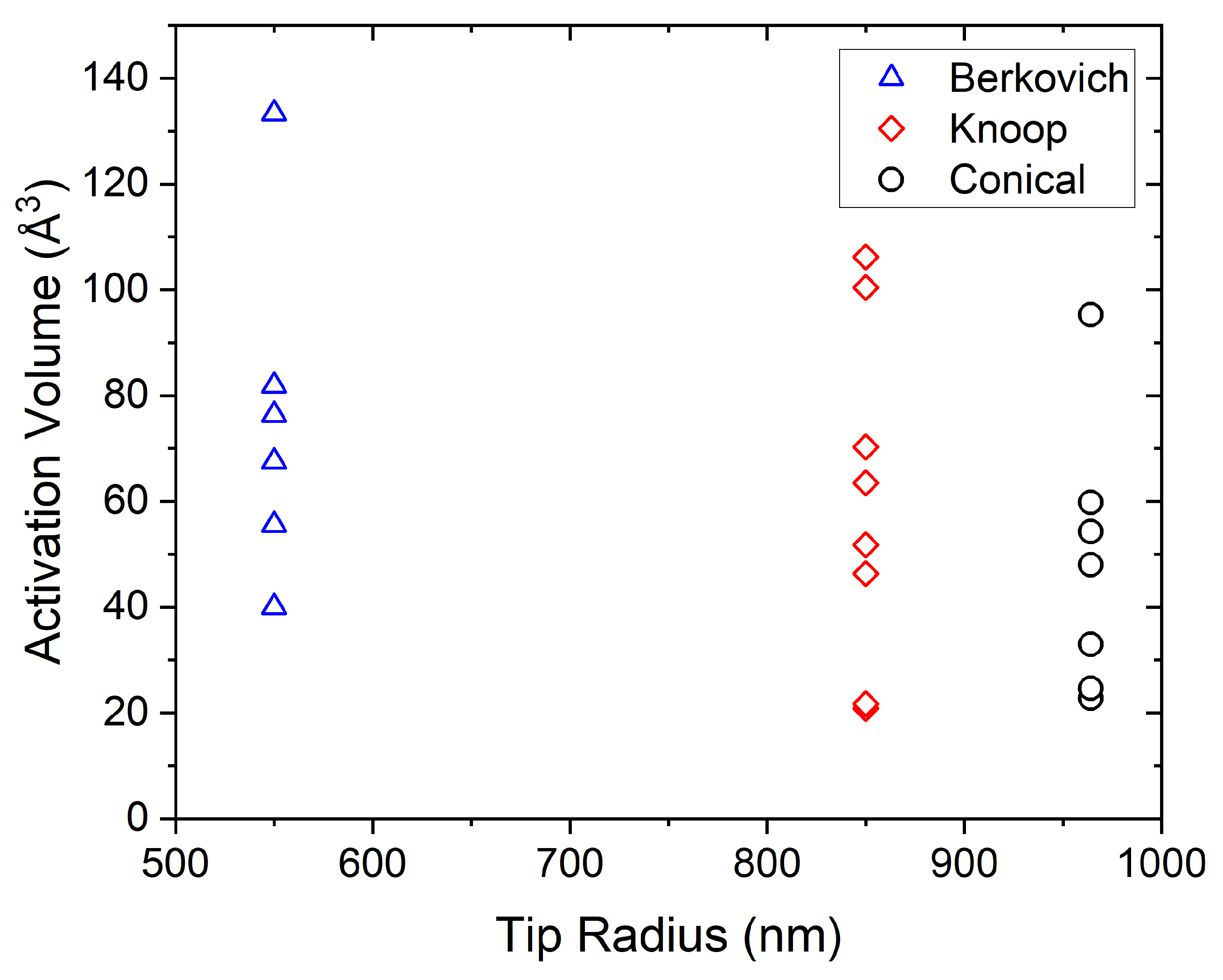
| Berkovich (n = 59) | 550 | 0.529 ± 0.106 | 0.207 | 15.195 ± 1.078 | 0.071 |
| Knoop (n = 108) | 850 | 0.376 ± 0.099 | 0.259 | 18.782 ± 1.628 | 0.083 |
| Conical (n = 75) | 964 | 0.324 ± 0.060 | 0.186 | 12.052 ± 0.058 | 0.058 |
Disclaimer/Publisher’s Note: The statements, opinions and data contained in all publications are solely those of the individual author(s) and contributor(s) and not of MDPI and/or the editor(s). MDPI and/or the editor(s) disclaim responsibility for any injury to people or property resulting from any ideas, methods, instructions or products referred to in the content. |
© 2025 by the authors. Licensee MDPI, Basel, Switzerland. This article is an open access article distributed under the terms and conditions of the Creative Commons Attribution (CC BY) license (https://creativecommons.org/licenses/by/4.0/).
Share and Cite
Chamberlain, M.C.; Burch, A.C.; Zečević, M.; Manner, V.W.; Cawkwell, M.J.; Bahr, D.F. Orientation-Dependent Nanomechanical Behavior of Pentaerythritol Tetranitrate as Probed by Multiple Nanoindentation Tip Geometries. Crystals 2025, 15, 426. https://doi.org/10.3390/cryst15050426
Chamberlain MC, Burch AC, Zečević M, Manner VW, Cawkwell MJ, Bahr DF. Orientation-Dependent Nanomechanical Behavior of Pentaerythritol Tetranitrate as Probed by Multiple Nanoindentation Tip Geometries. Crystals. 2025; 15(5):426. https://doi.org/10.3390/cryst15050426
Chicago/Turabian StyleChamberlain, Morgan C., Alexandra C. Burch, Milovan Zečević, Virginia W. Manner, Marc J. Cawkwell, and David F. Bahr. 2025. "Orientation-Dependent Nanomechanical Behavior of Pentaerythritol Tetranitrate as Probed by Multiple Nanoindentation Tip Geometries" Crystals 15, no. 5: 426. https://doi.org/10.3390/cryst15050426
APA StyleChamberlain, M. C., Burch, A. C., Zečević, M., Manner, V. W., Cawkwell, M. J., & Bahr, D. F. (2025). Orientation-Dependent Nanomechanical Behavior of Pentaerythritol Tetranitrate as Probed by Multiple Nanoindentation Tip Geometries. Crystals, 15(5), 426. https://doi.org/10.3390/cryst15050426