Article

Energy and Resource Efficient Continuous Cooling Crystallization with Modular Lab-Scale Equipment

by
Norbert Kockmann
1,*,
Mira Schmalenberg
1,
Benedikt Strakeljahn
2 and
Kerstin Wohlgemuth
2,*
1
Laboratory of Equipment Design, Faculty of Biochemical and Chemical Engineering, TU Dortmund University, Emil-Figge-Str. 68, 44227 Dortmund, Germany
2
Laboratory of Plant and Process Technology, Faculty of Biochemical and Chemical Engineering, TU Dortmund University, Emil-Figge-Str. 70, 44227 Dortmund, Germany
*
Authors to whom correspondence should be addressed.
Crystals 2025, 15(5), 421; https://doi.org/10.3390/cryst15050421
Submission received: 31 March 2025 / Revised: 24 April 2025 / Accepted: 25 April 2025 / Published: 29 April 2025
(This article belongs to the Special Issue Crystallisation Advances)

Abstract

:
Small-scale modular apparatuses in continuously operated plants are promising for current and future production processes in fine and specialty chemistry. Different lab-scale crystallizers have been developed and characterized as part of the ENPRO-TeiA project—separation processes with efficient and intelligent apparatuses. Two research groups at TU Dortmund University have investigated four miniaturized crystallization apparatuses for cooling crystallization and characterized them for scaling up to pilot scale with industrial partners. The use in an industrial environment was successfully demonstrated for two types of crystallizers: the stirred tank cascade as well as a draft tube baffle crystallizer. The ENPRO-TeiA project was thus able to prototypically demonstrate the manufacturer-independent investigation and scaling of modular systems for the crystallization step, which is an essential cornerstone for the process development acceleration for sustainable production in the pharmaceutical and chemical industries.

1. Introduction

Fine chemical production faces several challenges, including stringent regulatory requirements, high production costs, and the need for precise quality control. Additionally, the industry must adapt to fluctuating market demands and environmental concerns [1]. A promising solution is the adoption of small-scale, modular, and continuously operated equipment and plants [2,3]. These systems offer flexibility, scalability, and efficiency, allowing for rapid adjustments to production processes [4]. Modular plants can be easily reconfigured to produce different chemicals, reducing downtime and increasing responsiveness to market changes [5]. Continuous processing enhances product consistency and reduces waste [6], but is still limited for laboratory-scale applications [7,8].
Crystallization plays a crucial role in fine chemical production and pharmaceutical manufacturing [9,10] by enabling the separation and purification of solid compounds from liquid solutions. It ensures high purity and specific particle size distribution, which are essential for the quality of fine chemicals [11]. However, solids generation and handling are challenging in small-scale equipment [12] and in continuous flow [13], but in recent years, strategies to handle these were developed [14,15]. Modular automation further enhances production efficiency by integrating advanced process control systems that can quickly adapt to changing production requirements [16]. Process development has to be adjusted to the small-scale, modular approach, but can lead to much shorter development times and facilitate scale-up [17]. In the consumer electronics industry, rapidly responding to market needs requires a shift towards flexible production modes. Technologies such as 3D printing and rapid prototyping enable faster product development and customization, ensuring timely delivery of new products [18]. Starting from the 2009 Tutzing Symposion [19], different activities resulted in the ENPRO initiative.
The ENPRO initiative—Energy Efficiency and Process Acceleration—started in 2014 with the first four projects on modular process engineering, where owners and operators, suppliers, and various universities collaborate closely together [20]. The aim of the projects is to enhance the energy efficiency of chemical production processes by developing different technologies, not yet established in the market, that can significantly shorten the lead times of innovation projects [5,21]. This is particularly achieved through the transition from batch production to continuous processes [22], modularization of equipment [23,24], automation technology [25], logistic processes [26], and data integration across the entire value chain [27]. The ENPRO collaborative projects made significant contributions to improving energy efficiency in the process industry. Similar projects in other countries increased the momentum in modular production [23,28]. In ENPRO, the functionality of this new modular technology has been successfully demonstrated through extensive testing in various laboratory and pilot plant facilities [29], and it will be expanded for new application areas and supplier sectors in subsequent projects [20].
The production of active pharmaceutical ingredients as well as other fine and specialty chemicals is still often performed in batch operations in multipurpose plants, which is in contrast to petrochemical base chemicals [30]. Transitioning from batch to continuous operation, even in small-scale and product development settings, can offer enormous potential for efficiency gains and time savings [22,31,32,33]. The main advantages of running a continuous operation instead of a batch operation include a constant energy demand and simplified energy integration within the process [34], lower installed capacity, smaller plant volumes with higher product throughput, and reduced operational fluctuations in the process [22,35]. Additionally, scaling up batch processes often requires adjustments in mixing, dispersion, and heat transfer that may compromise product quality or process efficiency. As a result, there is a noticeable trend in both research and industry towards transitioning from batch to continuous operations. Continuous processing with integrated sensors allows for a high degree of automation and stable operation [36,37], which helps in minimizing quality fluctuations. Furthermore, continuous systems typically require smaller processing equipment compared to batch processes, hence, enhancing overall process safety [38].
In this contribution, the results in the research project “Separation Processes with Efficient and Intelligent Equipment” (TeiA) are presented for four different laboratory-scale continuous cooling crystallizers with their typical characteristics. The role of integrated sensors is shortly introduced; these sensors can be used for optimized solvent management to control the process for optimal product yield and quality. Modularity concepts are presented for the process steps that allow for particularly resource-efficient operation, with flexibility to use different substance systems. Here, l-alanine and glycine were chosen as model substance due to their good solubility and crystal-shape characteristics [39]. The amino acids are representative of organic small molecules with their low density difference to water for good suspension. For cooling crystallization, four different crystallizer concepts, the miniaturized draft tube baffle (DTB) crystallizer, the continuously operated vessel cascade in mixed-suspension mixed product removal operation (MSMPR), the helical tube crystallizer in coiled flow inverter style, and finally, the continuous oscillatory baffled crystallizer (COBC), were characterized in the lab to evaluate them for continuous operation. A similar study was presented by Yu et al. [40] for anti-solvent crystallization of paracetamol.
Particularly, equipment designed for operation within a volume flow range of 10–100 mL min⁻1 forms a technology platform between pilot plant and production for products with small tonnages. However, to remain competitive in today’s volatile markets, structured and rapid process development is essential. The objective was to characterize these four continuously operated crystallizers and derive generally applicable rules for process design and operation. Test systems from industrial project partners were used in this context. After evaluating the individual equipment concepts, successful designs were validated and assessed in an industrial environment. Subsequently, the advantages of transitioning from batch to continuous crystallization—such as increased product quality and production efficiency—were evaluated, primarily enabled by the newly developed measurement technology within the project.

2. Modular and Smart Equipment and Plants

In the following, the basic characteristics of modularization and smart equipment with sensors are presented, see Figure 1 for the basic concept, before the main topics on four different lab crystallizers are presented and discussed. In this contribution, smart equipment means devices with highly integrated sensors and automation in a modular, flexible setup.

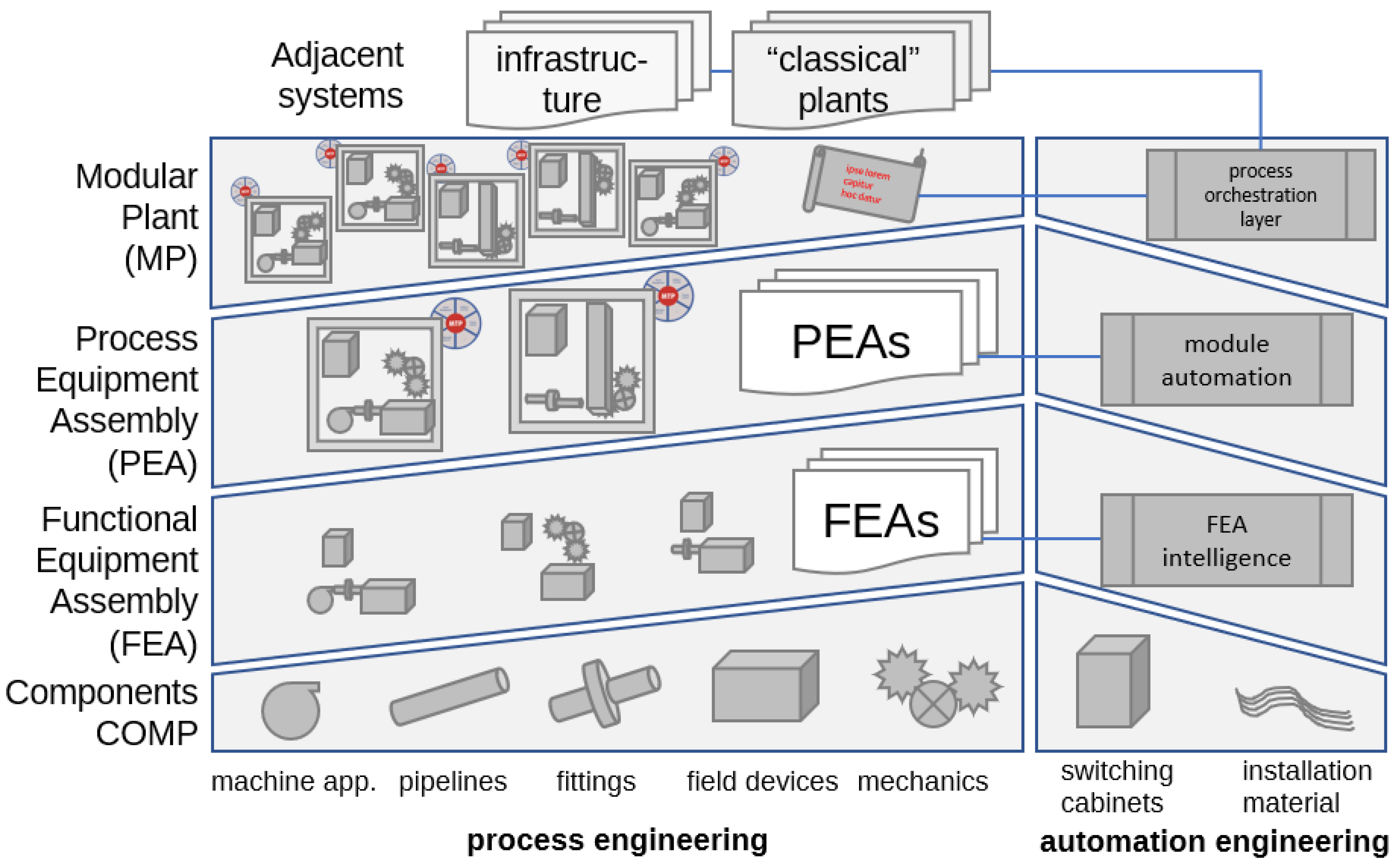
2.1. Modular Equipment and Automation

Modularization of equipment and (bio-)chemical production plants is quite old and an ongoing development process. Most recently, a status paper was published from the Dechema working groups of Cost Engineering and Modular Plants, indicating two different modular configurations with particular benefits in the different chemical applications ranging from large-scale plants for basic chemicals to flexibly reconfigurable production plants for fine chemicals [42]. The devices discussed here belong to the modular-flexible type, able to be reconfigured after a production campaign. Here, the investment costs are estimated to be higher; however, the economic benefit originates in the rapid market supply. In [42], some case studies are given in comparison with conventional plant and modular-construction equipment. Further activities and results of standardization of modular plants with modular automation are presented in [41]. Although often mentioned in the reports, sensors are not as visible in the publications as their importance in processing demands. Hence, the ENPRO-TeiA project included sensor development and miniaturization, too, for responsive and smart equipment.
Although the current standardization activities focus on dosing and reaction modules, separation steps are important, too, and were already part of other ENPRO projects. A small-scale distillation column was developed, fully automated, and characterized in the ORCA project (Orchestration of Modular Plants) [43]. A stirred-pulsed solvent extraction column [44] was automated and further characterized [21] concerning the resource-effective operation and process development. Here, the crystallization step, which is a very important downstream operation in fine chemicals production, will be presented in the framework of modular and small-scale equipment.

2.2. Sensors and Automation

For continuous processing, it is very important to perform minimally invasive measurements, which are often represented by integrated optical and electrical sensors. Impedance sensors play a crucial role in various process applications across the chemical industry. One significant area of investigation is foam detection, where ultra-broadband millimeter wave frequency modulated continuous wave (FMCW) radar is employed to identify foaming issues that can impede efficiency in chemical processes [45]. Early detection of foam allows for timely interventions, enhancing overall operational performance and efficiency. In addition to foam detection, electrical impedance tomography (EIT) has emerged as a powerful technique for determining the spatial conductivity distribution within measurement environments. Utilizing fast code-division-multiplexing with orthogonal codes [46], EIT facilitates rapid assessments that are applicable in diverse fields such as biomedical imaging and industrial process monitoring [47]. Since multiphase processes have inherent fluctuations and statistical noise, determination of accuracy is not simple and can only be estimated from comparable measurements. The developed EIT sensor reaches a “yet unachieved combination of measurement precision, accuracy and dynamic range, as well as a measurement and image reconstruction rate of up to 1000 frames per second” [48]. Moreover, accurate measurement of electrical conductivity in liquids is vital for numerous industrial processes, including water desalination, cleaning operations, and the mixing of various liquids [49]. Understanding the conductivity characteristics helps in optimizing these processes and ensuring quality control.
Lastly, advancements in soft-field electromagnetic tomography systems enable fast and precise imaging of multiphase flows [48]. These systems are essential for process development and optimization within the industry, providing valuable insights into complex multiphase interactions that occur during production.
Sensors are always integrated in plant automation. Modular automation was developed within ENPRO-ORCA project and is a prerequisite for smart modular plants, see also [50]. With reliable and in-line measurements, a proper and efficient control of modular plants is possible. Each unit of modular equipment, also called a process equipment assembly (PEA), has its own sensors and control circuits, which are orchestrated by the Process Orchestration Layer (POL). Hence, PEAs can also be operated on their own or with support from other PEAs and the surrounding infrastructure without higher effort. This also has an influence on the process development of critical process steps, which often can be achieved without having the entire plant with its complexity. This was shown in the ENPRO-SMekT [51] and VoPa projects [52].

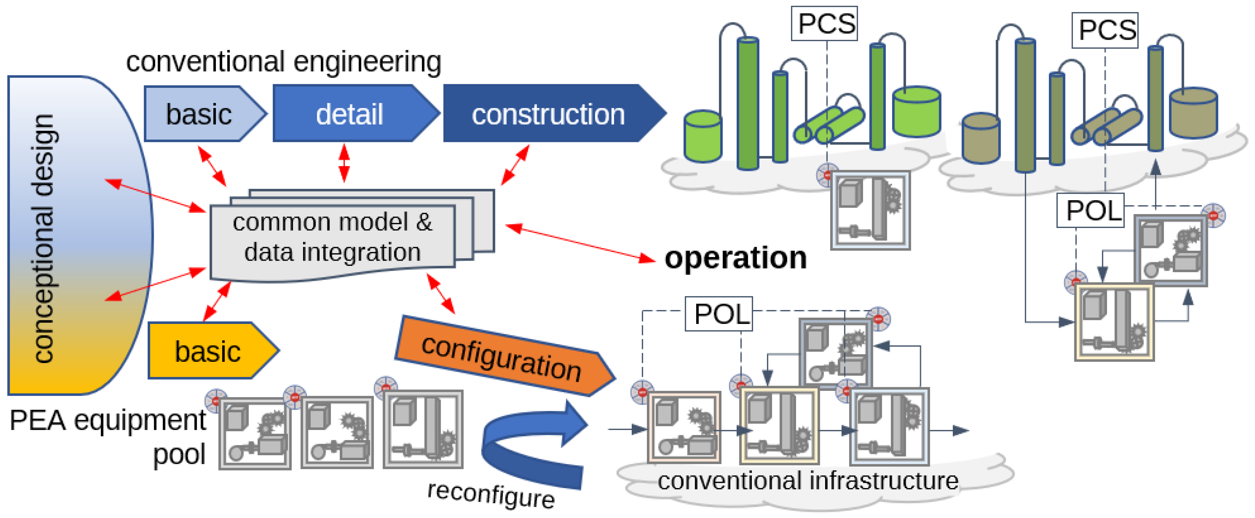
2.3. Modular Process Development and Transfer to Production

In modular plant engineering, process development and rapid transfer to production play a central role in the acceleration process. The engineering workflow begins with a conceptual phase, followed by basic and detailed engineering across various disciplines, see Figure 2, upper part, resulting in process schemes and piping and instrumentation diagrams (P&IDs). Conventional engineering can lead to either greenfield or updated brownfield plants, with monolithic plants automated using a Process Control System (PCS). In contrast, a modular approach configures chemical plants using predefined Process Equipment Assemblies (PEAs), each equipped with its own Module Technology Package (MTP), see Figure 2, lower part. These PEAs emerge from detailed engineering and include individual control systems and safety concepts. In hybrid plants, PEAs can connect to either brownfield or greenfield sections, necessitating communication between the PCS and the Plant Operations Layer (POL) for effective operation. This integrated strategy enhances flexibility and efficiency in the design and operation of chemical plants.
Common models and data integration are crucial in the engineering and operation workflow of modular plants, see left part of Figure 2. Various modeling and simulation tools can be utilized, ranging from conceptual process simulations such as Aspen and DWSIM to detailed modeling of reaction or separation steps using gPROMS, MATLAB, ANSYS, and COMSOL, see also [54] for a comparison. Additionally, plant operation simulations support model predictive control. A scenario is proposed in [53], where joint models and data integration bridge the gap between modular engineering for modular plants and conventional engineering for monolithic process plants [22]. Modular plants are integrated in existing units and infrastructure. This integration aims to enhance the efficiency of hybrid plant engineering, which combines elements from both approaches. Ultimately, hybrid plant engineering is supported by the collaboration of models and data from both conventional and modular methodologies. In the following, four different crystallizer concepts are described together with their impact on the process development and rapid scale-up to small-scale production.

3. Modular Crystallizers

In the following, four different continuously operated cooling crystallizers are presented with their characteristics in lab-scale operation. In general, continuous cooling crystallization can be performed in tubular devices or (stirred) vessels. Here, in particular, the four concepts investigated are a continuous oscillatory baffled crystallizer (COBC), a coiled flow inverter crystallizer (CFIC), a mixed suspension mixed product removal (MSMPR) cascade, and a draft tube baffle (DTB) crystallizer.

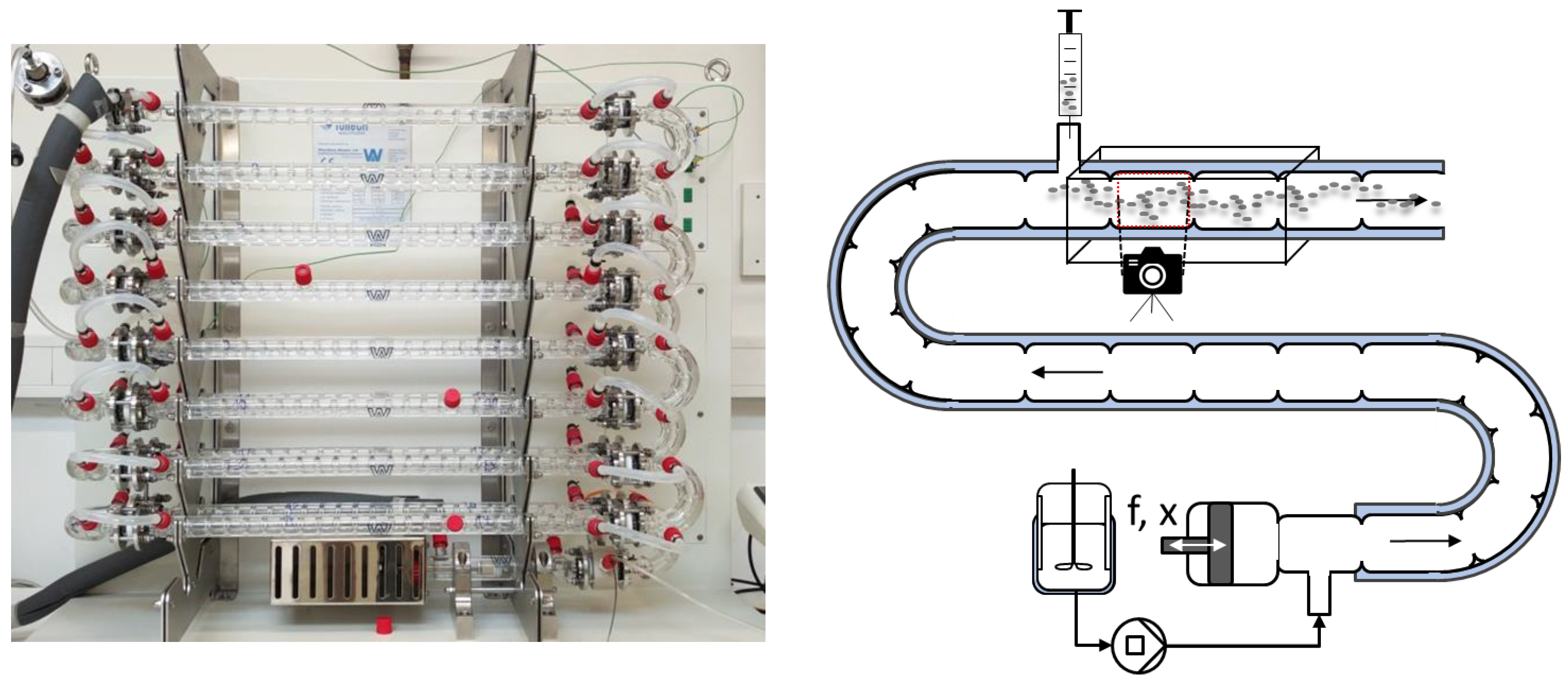
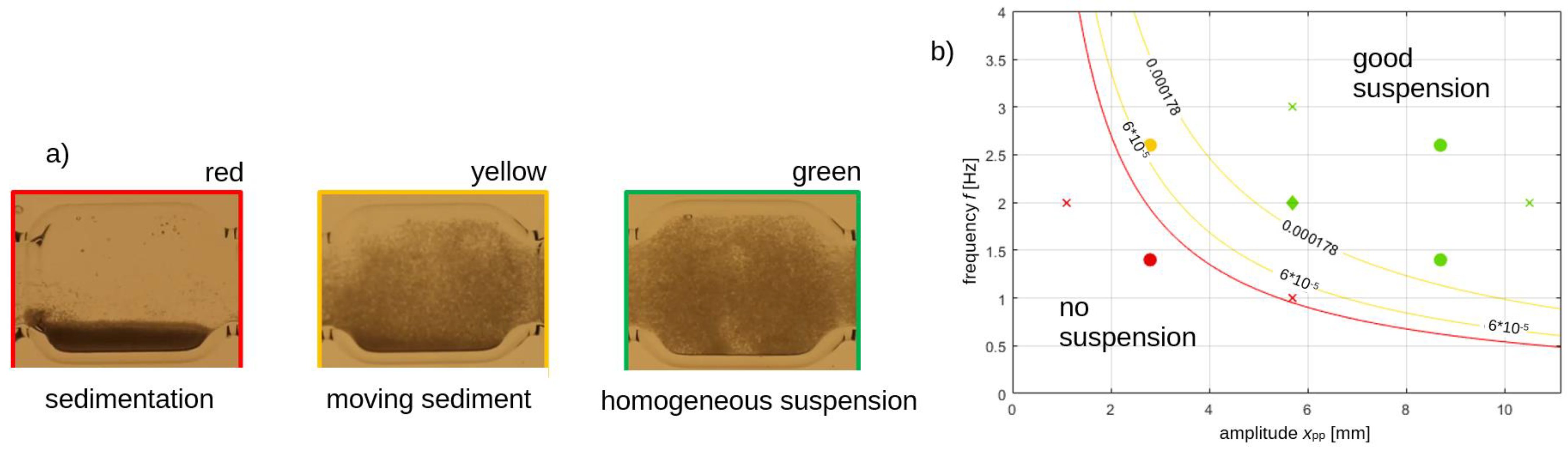
3.1. Continuous Oscillatory Baffled Crystallizer (COBC)

The continuous oscillatory baffled crystallizer (COBC) is a tubular crystallizer with periodic constrictions, in which a piston oscillates [55]. According to [56], the resulting vortices achieve a narrow residence time distribution, good suspension, and increased heat transfer between the medium and the double jacket. The characteristics of the COBC were experimentally investigated in more detail [57], while numerical studies are already available [58].
A schematic diagram and a photo of the COBC financed by the project are shown in Figure 3. The COBC consists of 15 straight segments and 16 semicircular segments in a modular design. All segments are equipped with a double jacket for precise temperature control, where two of the straight segments can be used for sampling. The total available length of the COBC is L = 14 m, which corresponds to an internal volume of V = 2.5 L. The individual chambers of the COBC are l = 22 mm long and have a diameter of da = 15 mm. The built-in constrictions have an opening diameter of di = 9 mm.
First, a systematic investigation was carried out with regard to the residence time distribution of the liquid phase. The parameters frequency f, amplitude X0, and the volume flow rate V ˙ t o t in the COBC were varied as variables influencing the residence time distribution. The target variable was the Bodenstein number,
B o = u · l D a x
which represents a measure between convective and diffusive mass transport [59]. A low Bodenstein number corresponds to a completely backmixed system such as a stirred tank, while Bodenstein numbers larger than 100 are assigned to an ideal plug flow without backmixing.
The widest residence time distribution with the lowest Bodenstein number of Bo = 10.4 was achieved at an operating point of f = 5 Hz, X0 = 8 mm, and V ˙ t o t = 20 mL min−1. The narrowest residence time distribution with the largest Bodenstein number of Bo = 44.1 was achieved at f = 5 Hz, X0 = 1 mm, and V ˙ t o t = 20 mL min−1, which lies between a completely backmixed stirred tank and an ideal plug flow. The residence time distribution can be adjusted by selecting the operating parameters and can be adapted to the required objective. However, in our experiments, we could not achieve a residence time behavior corresponding to plug flow behavior with Bo > 100.
Clogging due to sedimentation and spontaneous nucleation is a problem in COBCs [56,60]. It was therefore necessary to define an operating window in which sedimentation is prevented. When clogging was observed, the pulsation frequency and amplitude were increased, while the feed flow was lowered. In case of stopped oscillatory drive, the inlet flow was switched to water for purging the tube. Other measures depend on the crystal system and have to be tested beforehand on the basis of a safety analysis.
Based on a Design of Experiments (DoE), the influencing parameters of frequency f, amplitude X0, the volume flow rate V ˙ t o t , and the active length L of the COBC were varied in order to investigate the sedimentation of particles (l-alanine/water, d50 = 220 µm, wsolid = 10%) within the chambers of the COBC. To quantify the sedimentation, an image analysis method [61] was implemented to observe the effects of gravity. Figure 4a shows an example of sedimented and two possible suspension states in a chamber of the COBC. To predict the suspension state within the COBC, the observed suspension states were categorized as sediment, moving sediment, and homogeneous suspension [62]. The diagram in Figure 4b shows the suspension state as a function of the operating parameters of frequency f in Hz and amplitude Xpp in mm. The threshold of oscillation parameters that must be exceeded for sufficient suspension is clearly visible following the transition to turbulent energy dissipation, shown as a red line, which should always be reached in order to ensure effective mixing [63].
Further, the necessary energy input per cell can be calculated in order to achieve complete suspension. Thus, the minimum necessary frequency and amplitude directly determine operation with particles (l-alanine/water, d50 = 220 µm, wsolid = 10%). An operating window can now be determined a priori. However, by varying wsolid and, for example, the density difference Δρ between solution and solid, it is also possible to estimate the operating window for new material systems. Still, tests on the residence time distribution of the liquid and solid phase are necessary, depending on the system, over the short length of the COBC.

3.2. Coiled Flow Inverter Crystallizer (CFIC)

As a second crystallizer type, the coiled tubular cooling crystallizer wound in a coiled flow inverter (CFI) is investigated, since it is becoming an established crystallizer design [64]. In addition to cooling crystallization, the antisolvent crystallization is investigated due to the good mixing characteristics [40,65,66]. For solvent crystallization of paracetamol, Ganjare and Ranade [67] presented an anti-fouling strategy for longer plugging-free operation. Different material systems were investigated in helically coiled tubes with a strong emphasis on nanomaterials [68,69,70]. Only a few studies deal with detailed modeling of the precipitation processes [64]. Hence, experimental investigations are still necessary for a good process understanding.
The investigated modular setup can be divided into four functional equipment assemblies (FEAs) [71], see Figure 5. The first FEA comprises the feed vessel, solvent vessel, process pump, and a solenoid valve. The second FEA is a nucleation unit (ultrasonic unit USU) [71], consisting of a fluoroethylene propylene (FEP) tube (di = 1.6 mm, L = 6 m) wound in a CFI design in a conventional laboratory ultrasonic bath. This is followed by the CFI crystallizer (CFIC) for cooling crystallization, which consists of up to seven identically constructed crystallization units (CU) [62]. Each CU is wound in a tube-in-tube concept for countercurrent cooling with water (di,1 = 1.6 mm FEP, di,2 = 6 mm silicone, L = 7.8 m). A pressure sensor located at the CFIC input records the pressure loss over the CFI and can thus provide information on blockages. The fourth and final FEA is a non-invasive inline photosensor for suspension analysis, based on the work of Borchert and Sundmacher [72] and Huo et al. [73]. A temperature-controlled glass flow-through measuring cell was clamped under a microscope equipped with a digital camera. More information on visual online detection and measurement of crystals is given by [74,75,76,77,78,79], with emphasis on AI-assisted analysis. The measuring cell is followed by a solenoid valve, which can be coupled with the photosensor to decide whether the product is conveyed to the product tank (suspension) or to the waste tank (solvent).
Ultrasonic energy input is used by many research groups for the nucleation start in supersaturated solutions [80,81,82]. The modular concept of this unit was shown as beneficial for microfluidic applications [81], which can be transferred to other material systems [82]. Within the USU in Figure 5, the substance system l-alanine/water was used to investigate the supersaturation S, at which continuous nucleation can be generated with ultrasonic sonication. The nucleation could be non-invasively observed inline during the tests. A lower limit was observed, from which nucleation could occasionally be observed (S = 1.2), and an upper one, from which crystal nucleation could be observed in every experiment (S = 1.25). The transitional area is determined by cavitation and nucleation, both of which must be sufficiently pronounced to ensure nucleation. Due to the simple experimental setup in continuous flow, the investigations can be performed in series, where much experimental effort can be saved in comparison to batch nucleation testing [64]. The pressure sensor PIA + (P01) is important for early detection of growing pressure loss and potential fouling and blockage of the CFIC. In case of a high-pressure alarm, the three-way valve in the feed unit is switched to pure water to flush the CFIC for a certain period. With some experimental experience, the flush time could be adjusted to the residence time to ensure blockage-free operation for a longer period [71].
The flow-through measuring cell was able to non-invasively observe inline crystallization characteristics. In addition, an image analysis was used [62,72], which is based on evaluation routine methods from [83] and has been extended by the methods of [73]. This image analysis was used for the particle size analysis of the combination experiments of nucleation and crystal growth as well as for all particle size determinations regarding the DTB, see also Section 3.4. The accuracy of the AI-based particle detection method depended on the training setup in MatLab and obtained good values when compared to sedimentation detection [83]. The potential limitations are number of particles, in particular, when overlapping, which is dominating in particle concentrations of more than 5% solids. On the other hand, a concentration of only a few particles below 0.5% is also problematic due to insufficient statistical representation of the results. Particles smaller than 10 µm are often not detected due to the optical resolution. However, these values and limitations depend on the material system and sensor setup with the analysis algorithm, but are currently under further investigation.
The residence time distribution in the CFIC is relatively narrow for all investigations, and the behavior is very similar to that of an ideal plug flow (Bodenstein number > 100) [62,83]. Furthermore, the hypothesis of Hohmann et al. was confirmed: namely, that with a homogeneous suspension flow in a horizontal coiled tube crystallizer, the solid phase flows through the tube faster than a fluid element [62,83]. This indicates that the particles in the homogeneous suspension flow presumably do not adhere to the wall [73]. In contrast to Wiedmeyer et al. [84], who used vertically wound pipe coils, no classifying behavior of two different particle sizes could be observed for the mixed particle size fraction [83]. Depending on the required process conditions (strong uniform mixing vs. classifying behavior), it must be considered whether the crystallizer design should be wound horizontally or vertically and whether it should be in homogeneous suspension flow or stagnant flow.
The crystal growth behavior with seed crystals is essential for evaluating the crystallizer performance. Three different substance systems were used for this purpose. The most important test parameters and process data are listed in Table 1.
It should be noted that the CFI technology already used in the work of Hohmann [85] for two different inner diameters (4 mm and 10 mm) can also be scaled down to 1.6 mm and achieve similar results. This enables a savings of around 50% of the solution used compared to the CFI with a 4 mm inner diameter, as the suspension mass flow rate for a homogeneous suspension flow can be reduced by around half. Hence, process development can be carried out in an even more resource-efficient manner if required. The optical measuring cell was essential for non-invasive inline observation of the crystals and by using an inexpensive photosensor. The feasibility of continuously generating seed crystals with ultrasound was also demonstrated [71].

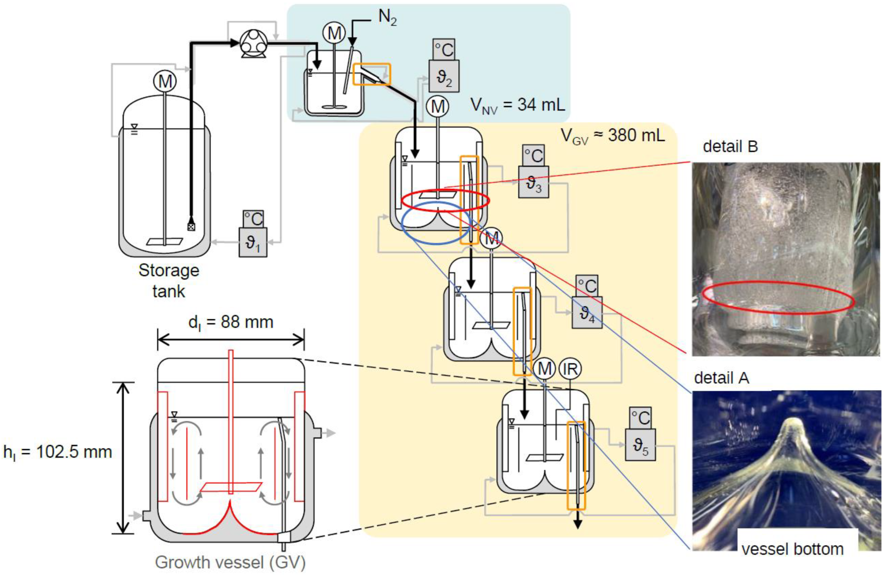
3.3. Mixed Suspension Mixed Product Removal (MSMPR) Cascade

In industrial crystallization, the mixed suspension mixed product removal (MSMPR) operation is often found in various continuously operated applications. To study the complex behavior of crystal growth and particle transport in the different vessel arrangements, lab-scale plants were investigated with different technical systems [86,87]. The MSMPR cascade investigated here is made up of three large functional units (FEAs) [63]. The feed tank with pump enables the supply of the mother solution to the vessels. The feed line is temperature-controlled to prevent clogging. The mother liquor is then transferred into the nucleation vessel, in which the solution is cooled by a defined ΔT. In order to avoid spontaneous, uncontrolled nucleation, this ΔT must be chosen deliberately. Lührmann et al. therefore defined a procedure for determining the so-called primary nucleation threshold (PNT) [88]. Nuclei are induced in the nucleation vessel by gassing, then flow from the nucleation vessel into the first growth vessel [88]. Nucleation should be suppressed in the growth vessel, which is why only a ΔT below the PNT may be set here. The grown crystals then flow from the vessel through an overflow tube into the following growth vessel or a product tank. The vessels were specially designed with a draft tube, which directs the flow axially, and a conical base that minimizes dead zones at the bottom of the vessel [11]. In case of a blocked transfer line, the feed was stopped, and the temperature in the heat jacket was increased to dissolve the solids. Similarly, a stirrer failure led to the feed stop and switch to pure water to remove the crystals from the system. The optimized structure of the crystallization vessels is shown in Figure 6.
The four connected components of the vessel are thus combined into two components. With an optimized vessel bottom and draft tube, the agitator can now be adjusted precisely, which results in better reproducibility of the particle suspension. If the vessel needs to be dismantled and cleaned, it can be opened quickly and rebuilt reliably and reproducibly. After successfully converting the growth vessels to a more stable, reproducible design, the set-up time of the cascade was reduced from approx. 1 h per vessel to less than 20 min per vessel.
A suitable measurement method was required for the installed “cleaning in place” concept and online process monitoring during crystallization. Conductivity measurement, used to prove the cleaning quality, was performed in parallel in the connected vessels. The parallel measurement enables simultaneous monitoring of crystallization at four points in the process, enabling long-term operation. Crystallization tests with an industrial substance system from our project partner showed transferability of the developed methods. The industrial system was monitored with an ATR-FTIR spectrometer, model ReactIR 15, from Mettler Toledo, Germany. Both the concentration of the target component and of by-products/impurities were determined during the tests. The results of the experiments provided valuable insights for the development and design of the demonstrators for crystallization.

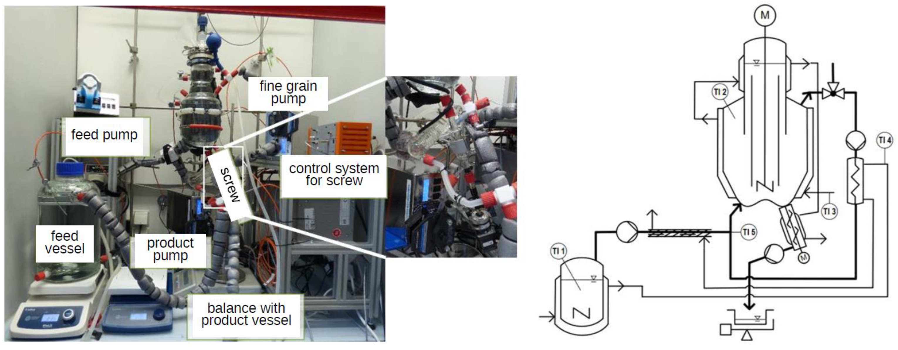
3.4. Draft Tube Baffle (DTB) Crystallizer

The draft tube baffle (DTB) crystallizer is quite widely used for large-scale continuous crystallization in process industries [89] and was a subject of scale-up in various studies [90,91]. Numerical simulation assisted the design and optimization of the DTB vessel, including flow studies [92,93] and particle characteristics [94] or geometrical optimization [95]. The scaled-down version of a DTB is quite rarely described in the literature, mainly with conventional equipment to investigate only selected characteristics [96].
The lab-scale DTB for the current investigations was designed on the basis of heuristics known from the literature and an 1100 L DTB scaled down by a geometrical factor of 10 [97] to an internal volume of 2100 mL. A first prototype was investigated with regard to its hydrodynamic properties, in particular, the suspension and residence time behavior [98]. Another prototype was designed with a double jacket and the stirrer inserted from above, see Figure 7. This allowed the bottom of the DTB to be fabricated in a W shape.
The specific design differences between the prototypes are described in detail in [97]. In order to ensure the operability of the prototypes, the peripherals have been continuously revised with heating of the feed inlet and connecting tubes to prevent blockages. In case of blockage, the temperature of the heating jacket was increased, and the feed was switched to water. Similarly, a stirrer failure was treated to avoid too large solids in the vessel.
To characterize the DTB, the residence time of the liquid and solid phase was investigated. The solid phase was varied in terms of its particle size, while the stirrer speed was varied from 600 rpm to the lower speed range (440 rpm). Interestingly, the hydraulic residence time of the liquid phase corresponds to the actual residence time, indicating a well-mixed system without dead zones or short-circuit flow. The residence time for the solid phase is significantly shorter. For the smaller sieve fraction of 90–125 µm for l-alanine in water, the actual residence time is 49–52 min, while for the larger sieve fraction of 180–250 µm, the actual residence time is only about 27 min and 14 min at the higher and lower stirrer speeds, respectively. This shows the particle classifying effect, which is enhanced for larger particles and can be further adjusted by the stirrer speed. The detailed evaluation of the results and implementation is described in [97].
For product removal, an Archimedes-type particle screw was developed and optimized. During the characterization of the particle screw, it was found that the concentration of solids behind the particle screw was higher than that in the agitator vessel above it. From this, it could be concluded that the particle screw was well suited to discharging classified particles from a system. The residence time of the solids is in the range between 65 and 98 s (depending on the solids content and particle size) and has no significant influence on the residence time in relation to the DTB. No significant change in crystal size could be identified after the screw as a result of abrasive effects. A detailed characterization of the particle screw can be found in [99].
For long-term operation, the l-alanine/water system was used, cooled down from 55 °C (at saturation concentration for 50 °C) to about 27 °C. The crystallization experiments were carried out over three consecutive days, see Figure 8. For this purpose, the suspension was drained from the DTB at the end of the experiment and left overnight in a temperature-controlled double-walled container stirred with a magnetic stirrer. The suspension stored overnight was poured into the DTB on the new test day, and the test was restarted. The relative yield showed that the system had already reduced around 60% of the possible supersaturation after the nucleation shower. It then needed another hour or so to stabilize at a relative yield of around 77–80%. At the beginning of the new test day, the supersaturation had been completely reduced overnight, as expected; hence, when starting up on days two and three, the yield returned to the same level as during the test. Disturbances such as fines blocking and unblocking also have an immediate effect on the yield in the system. This shows that the small crystallizer reacts significantly faster than larger industrial DTBs, which react very slowly to changes in the system [99].
Three boxplots are highlighted in green background, where an exemplary microscope image is shown for each. For the first and second day, it could be seen that the particle sizes were in approximately the same size range. On the third day, clearer fluctuations could be seen, particularly towards larger crystals. On average, the particle size was around 113–590 µm [99]. The oscillating behavior in the PSD on the third day of the test could also be perceived visually from the outside of the DTB. After filling the DTB with the suspension from the previous day, a good suspension was observed. As the process continued, some of the crystals settled in the lower brim of the DTB, and the system was depleted of nuclei. Later, nucleation was observed, which again led to increased turbidity of the solution and smaller crystals [99].

4. Demonstration of Energy and Resource Savings

As the main goal of the ENPRO collaborative project was to save energy and raw materials, together with the acceleration of process development, the developed equipment was tested in academic labs and transferred to an industrial environment. The results are described in the following.

4.1. Potential Savings in the Crystallization Step

The COBC was characterized with regard to its operating window for the substance system l-alanine/water. The tests showed that the baffled length and the volume flow rate through the COBC have no influence on the suspension. Hence, the residence time of the crystallization solution can be freely selected for controlled crystallization with reliable discharge of solids from the apparatus. The COBC is therefore suitable for a wide range of substance systems, regardless of the solubility curve or growth kinetics. A suspended state can be achieved by selecting the appropriate frequency and amplitude operating parameters. The modified temperature control concept can be used for other tubular crystallizers or for temperature control applications. However, the mechanical vibrations have to be considered as a weak point of the glass equipment.
With regard to the CFI technology, further gaps in the technology matrix have been closed by constructing and characterizing a small-scale CFI with an inner diameter of 1.6 mm. This made it possible to reduce the mass flow required to operate the tubular crystallizer, which was developed for an operating range from 30–40 g min−1 [51] to 16 g min−1 in the newly designed CFI. This means that 50% less solvent can be used to gain initial insights into the crystallization behavior of a substance system. In addition, the design was changed so that the crystallizer can be extended by crystallization units of the same design. The tube-in-tube countercurrent cooling design enables the use of particularly few cryostats, which may be of interest for initial trials on a process development scale.
The feasibility of continuous crystallization in the CFI has been demonstrated, particularly with the ultrasonic seed crystal unit in combination with an optical sensor [100] that can distinguish non-invasively between suspension and solution. Further development of this system will help to increase the technology readiness level, as an automated process contributes to long-term continuous operability. Compared to cleaning cycles already carried out in the literature, the cleaning time could be reduced by 20% [101], to only slightly more than 1% of the processing time [72].
In the MSMPR cascade, progress has been made towards trouble-free, long-term operation. By adapting the internal installations in the vessels, such as the draft tube and the mechanical stabilization of the agitator, it has been possible to design a vessel that shows reproducible suspension results. Due to the special conical shape of the vessel bottom, a discharge of solids for continuous operation has been achieved. The availability was increased by the established cleaning-in-place concept, which combines a defined cleaning procedure with online monitoring of the conductivity of the cleaning solution. The conductivity measurement provides an insight into the crystallization process, too. Each vessel can be monitored individually, and blockages in the transfer lines can be quickly identified. This enables long-term and controlled operation.
A small-scale draft tube baffle crystallizer was designed and characterized for cooling crystallization with fines separation in continuous laboratory operation. Start-up variants were evaluated, e.g., with regard to minimizing solvent consumption or avoiding blockages in the system. A new type of particle screw was designed to discharge the suspension and counteract blockages. The particle screw can also be used for other stirred tank crystallizers or reactors in order to convey suspensions on a very small scale. In the future, the fines dissolution will be further revised and the degree of automation increased to extend to the operation of evaporation crystallization.
In conclusion, the main characteristics of the four cooling crystallizers are summarized in the following table. The given values are rough estimations from our own experience; however, they can vary compared to other material systems, in particular with different crystal shapes, viscosity of the mother liquor, and SL density difference.
The preliminary data given in Table 2 are valid for l-alanine, glycine, and the tested conditions. Further improvements in process and material conditions can lead to optimized values.

4.2. Industrial Demonstrators

Two different crystallizers from the lab development were transferred to an industrial partner and tested with typical systems from production processes. The DTB crystallizer manufactured by TU Dortmund University and a larger growth vessel from the MSMPR cascade were integrated into a lab frame of an industrial partner. A 2 L jacketed glass reactor served as a feed vessel, where gear pumps were used to transfer the feed solution. Peristaltic pumps from Watson Marlow (Wernau, Germany) were provided to pump the suspension from the two crystallizers. Both crystallizers can be operated alone in this setup, but the MSMSPR vessel cascade can also be connected downstream of the DTB crystallizer as a buffer vessel. The setup can be seen in Figure 9 left, and the entire fume hood is shown in Figure 9 right.
Few modifications were made to the DTB crystallizer to enable long-term operation with the new substance system. The draft tube and the stirrer made from glass could not withstand the mechanical stresses caused by the long stirrer bar. Both parts were replaced by parts made from stainless steel with PEEK coating. Further, due to the length of the stirrer, it was also not possible to achieve a high speed for sufficient suspension. Improved agitator bearings integrated into the draft tube ensured smooth agitator operation. As a result, the main tests with the demonstrator were carried out in the growth vessel. The functionality of the integrated sensor was demonstrated during the test week. The required quality of the investigated material system was achieved by continuous evaporation crystallization. The impedance sensor made it possible to qualitatively track concentration fluctuations in the crystallizer. Both test systems could be tested as continuous processes during the course of the project and delivered good results in terms of yield and quality.

4.3. Potential Energy and Raw Material Savings in the Entire Process

The tests carried out in the project for the selected products could be successfully transferred from the laboratory to a pilot scale. In the pilot scale, campaigns with a throughput of 2 to 10 kg product/hour were carried out with industrially relevant products and solutions. The overall process for manufacturing the product group could be made more efficient. The required product quality was easily achieved, but improving the yield required additional equipment such as heat exchangers for heat integration, recirculation of process streams, and inline monitoring of product quality.
In addition to the economic aspects that were investigated, the pilot-scale implementation also provided important insights into working methods and test execution. The running time of the system on a test day was limited to a maximum of 12 to 20 h and was achieved by staggering the work of the employees. The stopping point of the system, i.e., the state in which the systems could remain overnight to enable a quick restart the next day, was also precisely defined. All recognized dangers were evaluated and could be intercepted via the infrastructure. As the products in question had melting points well above room temperature, any challenges that arose had to be solved during the ongoing tests. Only one infrastructure skid was available for the tests, and therefore, the process could only be mapped by replacing the PEAs in the skid. The modular design and automation according to the MTP concept proved to be extremely advantageous for this, as it meant that the PEAs could be replaced within 8 h. Some minor effort had to be expended for the adaption of the existing control system, but this could be achieved beforehand on the basis of the experience from the ENPRO-ORCA project [50,102].
The basic principles acquired in the project with regard to process engineering, plant engineering, and control engineering issues allow an initial evaluation to be made with regard to material and energy savings. By converting a standard batch process to a modular continuous process, there is a significant reduction in the volume of the product-containing phase. This results in a significant reduction in the required plant volume and, in combination with miniaturized equipment, enables a further reduction in the plant volume. The mass balances of the processing variants were compared, and the materials used and material flows generated were divided into groups, standardized to the manufactured product quantity in an initial calculation, and the sum of the material groups was calculated. As a result, a reduction in the quantity of required materials by >70% was achieved.
In a further step, results based on investigations in funded projects and designed plants were analyzed in terms of CO2 equivalent savings. Evaluations were also made regarding the generation of CO2 equivalents for the production of one kilogram of a typical industrial product in batch mode by evaluating tests in the process development pilot plant. For this purpose, the energy consumption and all materials required were determined. Both were converted into CO2 equivalents, where savings of more than 40% in CO2 (e)/year could be demonstrated. Since we have developed lab-scale equipment, detailed energy saving values are not representative for industrial applications in production due to missing separation and recycle streams, improved thermal insulation of larger equipment, and unknown start-up, shut down and cleaning efforts. Further, due to the high variety of possible products in fine chemical production, a detailed analysis for each product is necessary. Hence, a simple “kWh per kg of product” number is not possible to determine from the presented investigations.
Several ENPRO projects yielded in process knowledge on the various basic operations required in pilot tests in order to obtain results regarding process design, product yield, auxiliary material requirements, and throughput. The results obtained were used to carry out calculations in order to draw up specifications for typical PEAs and initial estimates of the dimensions for the main units. The calculation of CO2 equivalent savings was divided into the following areas.
-
Product yield: By increasing the yield, the total amount of CO2 equivalents was reduced, i.e., that of energy input and raw material consumption. In studies on typical industrial product groups, yield increases of 5 to 20% were achieved. To calculate the savings, a yield increase of 10% was used, and thus, the savings in CO2 equivalents was calculated.
-
Raw material/auxiliary material consumption: By using continuous modular systems that have all the basic operations required and are equipped with internal and cross-module recirculation, the amount of solvent required and the amount of waste produced can be reduced. The need for auxiliary materials can also be reduced or even eliminated by intensifying heat transfer and mass transfer and using new technologies. For the typical industrial products investigated, savings in auxiliary materials of 10 to 70% were achieved. To calculate the savings, an excipient savings of 40% was estimated, and thus, a savings in CO2 equivalents was calculated. Assuming that the thermal supply, the product quantity to be produced, and the running time are very similar, a reduction in power demand of 85% was expected through the use of a continuous modular system. Measurements and calculations based on pilot plants have shown that reductions of up to 90% are possible.
-
Hold-up reduction: The internal volume of a system was determined to be 20 to 50% lower on a pilot plant scale. For further calculation, 30% was assumed, from which a reduction in CO2 equivalents was determined.
Further savings in terms of energy use are possible through energy integration measures, but these have not been investigated in the current funded projects; in particular, the cross-module integration of the measures still presents challenges. Summing up the expectations from the three areas results in savings of typical industrial products in CO2 equivalents, which represents a saving of >35% in CO2 equivalents compared to the batch process for the same product group. Through further work, in particular, on the precise definition of a production plant, the determined CO2 (e) savings can be specified in relation to an investment in a modular production plant. The numbers were aggregated for all ENPRO projects in 2022 and cumulated in 3 TWh for the German chemical industry [103].
It should be noted at this point that this is an initial example of the use of modular production technology and that it is highly likely that there will be deviations in other implementation examples. Structured recording of energy savings is absolutely essential for further implementation of modular production technology.

5. Conclusions

Modular chemical plant and production technology can help to reduce energy consumption in the manufacture of chemical and pharmaceutical products. The consistent streamlining of manufacturing processes towards small, modular, and highly efficient production plants also makes it possible to significantly reduce mass flow rates and consumption of utilities and energy. This reduces the CO2 footprint and avoids the generation of waste. The potential effects were shown with four different crystallization units promising utility, solvent, and energy savings of from 30 up to 90% depending on the related application. Further positive effects can be achieved through energy integration measures, but there are challenges to be overcome in the operation of multi-product plants. In particular, effects relating to the start-up/shut-down of several products in the plant complex must be investigated, as well as concepts for only partial operation of the plant and the possibility of intermediate energy storage.
With regard to energy integration in modular multi-product plants, there are currently insufficient studies and statements on possible implementation, so a need for further research activities is seen here. The technologies available on the market are geared towards energy integration in large-scale plants and, in particular, the economic benefits for multi-product plants have not been sufficiently demonstrated or proven. The proof starts with investigating process opportunities for the continuously operated PEA lab toolbox. Currently, several different equipment and process concepts are under investigation, such as Taylor–Couette [104] or Archimedes screw crystallizers [105], as well as DTB under vacuum operation and bubbly flow crystallization [106]. In particular, slug-flow crystallizers gain more importance in various laboratory studies [107], such as pharmaceutical product investigations [2,108,109] or small molecule purification [110]. Although the different technologies are currently under investigation, the multitude of opportunities should be used to investigate different crystallization processes with individual product considerations. Due to the modular approach, the novel crystallization technology provides good scale-up potential for the continuous operation conditions, leading to energy- and resource-efficient production conditions.

Author Contributions

Conceptualization: N.K.; methodology: N.K. and K.W.; validation: M.S. and B.S.; formal analysis: N.K. and K.W.; investigation: all; resources: N.K. and K.W.; writing—original draft preparation: N.K., K.W., M.S. and B.S.; writing—review and editing: N.K., K.W. and M.S.; visualization: all; supervision: N.K. and K.W.; project administration: N.K.; funding acquisition: N.K. and K.W. All authors have read and agreed to the published version of the manuscript.

Funding

This research was funded by the German Federal Ministry of Economic Affairs and Energy (BMWi) and the Project Management Jülich (PtJ) as part of the ENPRO2.0 initiative (Ref. no.03ET1528A).

Data Availability Statement

The original contributions presented in the study are included in the article. Further inquiries can be directed to the corresponding authors.

Acknowledgments

Many thanks to our project partners, in particular, M. Dittmann, H. Freund, L. Kaufhold, D. Maillard, and A. Meijer in Darmstadt, M. Brandenburg, S. Durickij, J. Förster, and J. Tebruegge in Duisburg, H. Winterbauer in Hofheim, A. Krutzenbichler, S. Kuchinke, T. Weidner, and M. Zhao in Wernau, as well as N. Karsch, T. Musch, and S. Westerdick in Bochum. The authors thank Carsten Schrömges (TU Dortmund University, BCI Laboratory of Equipment Design) for his technical support and the German Federal Ministry for Economic Affairs and Climate Action (BMWK) for funding this research as part of the ENPRO TeiA project (grant number 03EN2100B).

Conflicts of Interest

On behalf of all authors, the corresponding authors state that there are no conflicts of interest.

Abbreviations

The following abbreviations are used in this manuscript.
ANSYSCFD simulation program package
ATR-FTIRAttenuated total reflection-Fourier-transformed IR
CFICoiled flow inverter
CIPCleaning in place
COBCContinuous oscillatory baffled crystallizer
COMSOLprocess simulation program
CUcrystallization units
DoEDesign of experiments
DTBDraft Tube Baffle
DWSIMProcess simulation program (dwsim.org, last access on 30 March 2025)
EITElectrical impedance tomography
ENPROEnergieeffizienz und Prozessbeschleunigung—Energy efficiency and process acceleration
FEAFunctional Equipment Assembly
FEPFluorinated polyethylene propylene
FMCWFrequency Modulated Continuous Wave
gPROMSnumerical simulation program
IRInfra-red
MATLABnumerical simulation program
MSMPRMixed suspension mixed product removal
MSZWmetastable zone width
MTPModular Type Package
ORCAENPRO project Orchestration of modular plants
P&IDPipe & Instrumentation Diagram
PCSProcess control system
PEAProcess Equipment Assembly
PNTPrimary nucleation threshold
POLProcess Orchestration Layer
PSDParticle size distribution
SLsolid–liquid
SMekTENPRO project Smart miniplant with continuous separation steps
USUultrasonic nucleation unit
VoPaENPRO project Fully-integrated particle generation

References

  1. Ciriminna, R.; Della Pina, C.; Luque, R.; Pagliaro, M. Reshoring fine chemical and pharmaceutical productions. Org. Process Res. Dev. 2024, 28, 3026–3034. [Google Scholar] [CrossRef]
  2. Testa, C.J.; Shvedova, K.; Hu, C.; Wu, W.; Born, S.C.; Takizawa, B.; Mascia, S. Heterogeneous crystallization as a process intensification technology in an integrated continuous manufacturing process for pharmaceuticals. Org. Process Res. Dev. 2021, 25, 225–238. [Google Scholar] [CrossRef]
  3. Silva, T.C.; Eppink, M.; Ottens, M. Automation and miniaturization: Enabling tools for fast, high-throughput process development in integrated continuous biomanufacturing. J. Chem. Technol. Biotechnol. 2022, 97, 2365–2375. [Google Scholar] [CrossRef]
  4. Bramsiepe, C.; Sievers, S.; Seifert, T.; Stefanidis, G.D.; Vlachos, D.G.; Schnitzer, H.; Muster, B.; Brunner, C.; Sanders, J.P.M.; Bruins, M.E.; et al. Low-cost small scale processing technologies for production applications in various environments—Mass produced factories. Chem. Eng. Process. Process Intensif. 2012, 51, 32–52. [Google Scholar] [CrossRef]
  5. Dechema. Modular Plants Flexible Chemical Production by Modularization and Standardization—Status Quo and Future Trends. 2016. Available online: https://dechema.de/dechema_media/modularplants.pdf (accessed on 30 March 2025).
  6. Hessel, V.; Escriba-Gelonch, M.; Bricout, J.; Tran, N.N.; Anastasopoulou, A.; Ferlin, F.; Valentini, F.; Lanari, D.; Vaccaro, L. Quantitative sustainability assessment of flow chemistry–from simple metrics to holistic assessment. ACS Sustain. Chem. Eng. 2021, 9, 9508–9540. [Google Scholar] [CrossRef]
  7. Cherkasov, N.; Adams, S.J.; Bainbridge, E.G.; Thornton, J.A. Continuous stirred tank reactors in fine chemical synthesis for efficient mixing, solids-handling, and rapid scale-up. React. Chem. Eng. 2023, 8, 266–277. [Google Scholar] [CrossRef]
  8. Schrimpf, M.; Esteban, J.; Warmeling, H.; Färber, T.; Behr, A.; Vorholt, A.J. Taylor-Couette reactor: Principles, design, and applications. AIChE J. 2021, 67, e17228. [Google Scholar] [CrossRef]
  9. Orehek, J.; Teslic, D.; Likozar, B. Continuous crystallization processes in pharmaceutical manufacturing: A review. Org. Process Res. Dev. 2020, 25, 16–42. [Google Scholar]
  10. Vaidya, S.N.; Agrawal, S.; Lambole, V.; Pimpale, A.; Telrandhe, U. Pharmaceutical manufacturing continuous crystallization procedures: A review. Asian J. Pharm. 2023, 17, 344–354. [Google Scholar]
  11. Temmel, E.; Lorenz, H. Advances in Industrial Crystallization. Crystals 2020, 10, 997. [Google Scholar] [CrossRef]
  12. Hessel, V.; Löb, P.; Löwe, H.; Kolb, G. Microreactor concepts and processing. In Micro Instrumentation: For High Throughput Experimentation and Process Intensification—A Tool for PAT; Koch, M.V., VandenBussche, K.M., Chrisman, R.W., Eds.; John Wiley & Sons: Hoboken, NJ, USA, 2007; pp. 85–129. [Google Scholar]
  13. Neugebauer, P.; Soritz, S.; Khinast, J.G.; Gruber-Woelfler, H. Enhanced sustainability with crystallization in continuous flow. Curr. Opin. Green Sustain. Chem. 2024, 48, 100937. [Google Scholar] [CrossRef]
  14. Wu, K.; Kuhn, S. Strategies for solids handling in microreactors. Chim. Oggi 2014, 32, 62. [Google Scholar]
  15. Hartman, R.L. Managing solids in microreactors for the upstream continuous processing of fine chemicals. Org. Process Res. Dev. 2012, 16, 870–887. [Google Scholar] [CrossRef]
  16. Bernshausen, J.; Haller, A.; Bloch, H.; Hoernicke, M.; Hensel, S.; Menschner, A.; Stutz, A.; Maurmaier, M.; Holm, T.; Schäfer, C.; et al. Plug & Produce auf dem Sprung in den Markt: Neuerungen in Spezifikation und Implementierung des MTP. Atp Mag. 2019, 61, 56–69. [Google Scholar]
  17. Grundemann, L.; Schoenitz, M.; Scholl, S. Shorter Time-to-Market with Micro-Conti Processes. Chem. Ing. Tech. 2012, 84, 685–693. [Google Scholar] [CrossRef]
  18. Zentel, K.M.; Fassbender, M.; Pauer, W.; Luinstra, G.A. 3D printing as chemical reaction engineering booster. In Advances in Chemical Engineering; Academic Press: Cambridge, MA, USA, 2020; Volume 56, pp. 97–137. [Google Scholar]
  19. Schembecker, G.; Bott, T. Die 50%-Idee-Vom Produkt zur Produktionsanlage in der halben Zeit. Chem. Ing. Tech. 2009, 81, 1094–1095. [Google Scholar] [CrossRef]
  20. Available online: http://enpro-initiative.de/ (accessed on 30 March 2025).
  21. Hohmann, L.; Kössl, K.; Kockmann, N.; Schembecker, G.; Bramsiepe, C. Modules in process industry—A life cycle definition. Chem. Eng. Process. Process Intensif. 2017, 111, 115–126. [Google Scholar] [CrossRef]
  22. Seifert, T.; Sievers, S.; Bramsiepe, C.; Schembecker, G. Small scale, modular and continuous: A new approach in plant design. Chem. Eng. Process. Process Intensif. 2012, 52, 140–150. [Google Scholar] [CrossRef]
  23. Baldea, M.; Edgar, T.F.; Stanley, B.L.; Kiss, A.A. Modular manufacturing processes: Status, challenges, and opportunities. AIChE J. 2017, 63, 4262–4272. [Google Scholar] [CrossRef]
  24. Kockmann, N. Modular equipment for chemical process development and small-scale production in multipurpose plants. ChemBioEng Rev. 2016, 3, 5–15. [Google Scholar] [CrossRef]
  25. Bamberg, A.; Urbas, L.; Bröcker, S.; Bortz, M.; Kockmann, N. The digital twin–your ingenious companion for process engineering and smart production. Chem. Eng. Technol. 2021, 44, 954–961. [Google Scholar] [CrossRef]
  26. Blumenstein, M.; Henkel, V.; Fay, A.; Stutz, A.; Scheuren, S.; Austermann, N. Integration of flexible transport systems into modular production-related logistics areas. In Proceedings of the 2023 IEEE 21st International Conference on Industrial Informatics (INDIN), Lemgo, Germany, 18–20 July 2023; pp. 1–8. [Google Scholar]
  27. Becker, T.; Lier, S.; Werners, B. Value of modular production concepts in future chemical industry production networks. Eur. J. Oper. Res. 2019, 276, 957–970. [Google Scholar] [CrossRef]
  28. Bielenberg, J.; Palou-Rivera, I. The RAPID Manufacturing Institute–Reenergizing US efforts in process intensification and modular chemical processing. Chem. Eng. Process. Process Intensif. 2019, 138, 49–54. [Google Scholar] [CrossRef]
  29. Dobler, T.; Buchheiser, S.; Gleiß, M.; Nirschl, H. Development and commissioning of a small-scale, modular and integrated plant for the quasi-continuous production of crystalline particles. Processes 2021, 9, 663. [Google Scholar] [CrossRef]
  30. Pollak, P. Fine Chemicals: The Industry and the Business; John Wiley & Sons: Hoboken, NJ, USA, 2011. [Google Scholar]
  31. Ma, Y.; Wu, S.; Macaringue, E.G.J.; Gong, J.; Wang, J. Recent Progress in Continuous Crystallization of Pharmaceutical Products: Precise Preparation and Control. Org. Process Res. Dev. 2020, 24, 1785–1801. [Google Scholar] [CrossRef]
  32. Wood, B.; Girard, K.P.; Polster, C.S.; Croker, D.M. Progress to date in the design and operation of continuous crystallization processes for pharmaceutical applications. Org. Process Res. Dev. 2019, 23, 122–144. [Google Scholar] [CrossRef]
  33. Kumar, R.; Thakur, A.K.; Banerjee, N.; Kumar, A.; Gaurav, G.K.; Arya, R.K. Liquid antisolvent crystallization of pharmaceutical compounds: Current status and future perspectives. Drug Deliv. Transl. Res. 2023, 13, 400–418. [Google Scholar] [CrossRef]
  34. Bennett, R.C. Crystallization Apparatus and Method. US Patent 3,873,275, 25 March 1975. [Google Scholar]
  35. Rogers, L.; Briggs, N.; Achermann, R.; Adamo, A.; Azad, M.; Brancazio, D.; Capellades, G.; Hammersmith, G.; Hart, T.; Imbrogno, J.; et al. Continuous production of five active pharmaceutical ingredients in flexible plug-and-play modules: A demonstration campaign. Org. Process Res. Dev. 2020, 24, 2183–2196. [Google Scholar] [CrossRef]
  36. Kadam, S.S.; Vissers, J.A.; Forgione, M.; Geertman, R.M.; Daudey, P.J.; Stankiewicz, A.I.; Kramer, H.J. Rapid crystallization process development strategy from lab to industrial scale with PAT tools in skid configuration. Org. Process Res. Dev. 2012, 16, 769–780. [Google Scholar] [CrossRef]
  37. Chen, X.; Kang, Q.; Li, Q.; Ye, F.; Liang, J.; Wang, H.; Yu, H.; Li, X.; Yang, C. Direct Optical Measurement for Particle Dynamics in Multiphase Reactors: Hardware Composition, Image Processing and Uncertainties. Ind. Eng. Chem. Res. 2024, 63, 22232–22252. [Google Scholar] [CrossRef]
  38. Gutmann, B.; Cantillo, D.; Kappe, C.O. Continuous-flow technology—A tool for the safe manufacturing of active pharmaceutical ingredients. Angew. Chem. Int. Ed. 2015, 54, 6688–6728. [Google Scholar] [CrossRef] [PubMed]
  39. Tumanov, N.A.; Boldyreva, E.V.; Kolesov, B.A.; Kurnosov, R.A.V.; Quesada Cabrera, R. Pressure-induced phase transitions in L-alanine, revisited. Struct. Sci. 2010, 66, 458–471. [Google Scholar]
  40. Yu, Y.; Robertson, P.K.; Ranade, V.V. Continuous antisolvent crystallization using fluidic devices: Fluidic oscillator, helical coil, and coiled flow inverter. Ind. Eng. Chem. Res. 2022, 61, 15000–15013. [Google Scholar] [CrossRef]
  41. Dechema. Modular Plants: Paradigm Shift—Describing Process Functionalities Instead of Specifying Equipment; Progress Report; Dechema: Frankfurt, Germany, 2022. [Google Scholar]
  42. Dechema. Cost Engineering for Modular Plants, Position Paper for the Evaluation of Different Plant Setups, Construction, and Operational Concepts; Dechema: Frankfurt, Germany, 2022. [Google Scholar]
  43. Grahl, L. Development and Automation of a Smart Distillation Unit for Modular Plants. Ph.D. Dissertation, TU Dortmund University, Dortmund, Germany, 2025. [Google Scholar]
  44. Schmalenberg, M.; Frede, T.A.; Mathias, C.; Kockmann, N. Efficient Shortcut Method for Determining the Process Window in Stirred-Pulsed Extraction Columns. Chem. Ing. Tech. 2021, 93, 466–472. [Google Scholar] [CrossRef]
  45. van Delden, M.; Westerdick, S.; Musch, T. Investigations on Foam Detection Utilizing Ultra-Broadband Millimeter Wave FMCW Radar. In Proceedings of the IEEE MTT-S International Microwave Workshop Series on Advanced Materials and Processes for RF and THz Applications (IMWS-AMP), Bochum, Germany, 16–18 July 2019; pp. 103–105. [Google Scholar]
  46. Gevers, M.; Gebhardt, P.; Westerdick, S.; Vogt, M.; Musch, T. Fast electrical impedance tomography based on code-division-multiplexing using orthogonal codes. IEEE Trans. Instrum. Meas. 2015, 64, 1188–1195. [Google Scholar] [CrossRef]
  47. Karsch, N.; Westerdick, S.; Musch, T.; Kaufhold, L.; Dittmann, M.; Mallach, M.; Tebrügge, J.; Förster, J.; Vogt, M. Electrical impedance spectroscopy: Machine learning in crystallization processes. Atp Magazin, 21 September 2021; pp. 88–93. [Google Scholar]
  48. Mallach, M.; Gevers, M.; Gebhardt, P.; Musch, T. Fast and precise soft-field electromagnetic tomography systems for multiphase flow imaging. Energies 2018, 11, 1199. [Google Scholar] [CrossRef]
  49. Vogt, M.; Hidalgo, S.; Musch, T.; Mallach, M.; Lange, T.; Förster, J. 3 Concepts for accurate electrical conductivity measurement of liquids in industrial process analytics. In Ama Science; Tagungsband: Nuremberg, Germany, 2019; Chapter 1.4; pp. 105–112. [Google Scholar]
  50. Kockmann, N.; Bittorf, L.; Krieger, W.; Reichmann, F.; Schmalenberg, M.; Soboll, S. Smart Equipment—A Perspective Paper. Chem. Ing. Tech. 2018, 90, 1806–1822. [Google Scholar] [CrossRef]
  51. Hohmann, L.; Löbnitz, L.; Menke, C.; Santhirakumaran, B.; Stier, P.; Stenger, F.; Dufour, F.; Wiese, G.; zur Horst-Meyer, S.; Kusserow, B.; et al. Continuous Downstream Processing of Amino Acids in a Modular Miniplant. Chem. Eng. Technol. 2018, 41, 1152–1164. [Google Scholar] [CrossRef]
  52. Dobler, T.; Höving, S.; Dreiser, C.; Gleiß, M.; Gröschen, M.; Henkel, A.; Hörne, M.; Schäfer, M.; Sonnenschein, J.; Wiese, G.; et al. From Lab to Pilot Scale: Commissioning of an Integrated Device for the Generation of Crystals. Chem. Eng. Technol. 2023, 46, 1511–1520. [Google Scholar] [CrossRef]
  53. Markay, A.; Fay, A.; Kockmann, N. Definition, Characterization, and Modeling of Hybrid Modular-Monolithic Process Plants. Chem. Ing. Tech. 2022, 94, 1117–1130. [Google Scholar] [CrossRef]
  54. Ramyashree, M.S.; Nandy, A.; Bohari, Y.R.; Pramodh, M.; Kumar, S.H.; Priya, S.S.; Sudhakar, K. Modeling and simulation of reactors for methanol production by CO2 reduction: A comparative study. Results Eng. 2024, 23, 102306. [Google Scholar]
  55. McGlone, T.; Briggs, N.E.B.; Clark, C.A.; Brown, C.J.; Sefcik, J.; Florence, A.J. Oscillatory Flow Reactors (OFRs) for Continuous Manufacturing and Crystallization. Org. Process Res. Dev. 2015, 19, 1186–1202. [Google Scholar] [CrossRef]
  56. Ni, X.; Liao, A. Effects of mixing, seeding, material of baffles and final temperature on solution crystallization of l-glutamic acid in an oscillatory baffled crystallizer. Chem. Eng. J. 2010, 156, 226–233. [Google Scholar] [CrossRef]
  57. Briggs, N.E.; McGinty, J.; McCabe, C.; Raval, V.; Sefcik, J.; Florence, A.J. Heat transfer and residence time distribution in plug flow continuous oscillatory baffled crystallizers. ACS Omega 2021, 6, 18352–18363. [Google Scholar] [CrossRef] [PubMed]
  58. McDonough, J.R.; Phan, A.N.; Harvey, A.P. Rapid process development using oscillatory baffled mesoreactors—A state-of-the-art review. Chem. Eng. J. 2015, 265, 110–121. [Google Scholar] [CrossRef]
  59. Kacker, R.; Regensburg, S.I.; Kramer, H.J.M. Residence time distribution of dispersed liquid and solid phase in a continuous oscillatory flow baffled crystallizer. Chem. Eng. J. 2017, 317, 413–423. [Google Scholar] [CrossRef]
  60. Briggs, N.E.B.; Schacht, U.; Raval, V.; McGlone, T.; Sefcik, J.; Florence, A.J. Seeded Crystallization of β-l-Glutamic Acid in a Continuous Oscillatory Baffled Crystallizer. Org. Process Res. Dev. 2015, 19, 1903–1911. [Google Scholar] [CrossRef]
  61. Termühlen, M.; Strakeljahn, B.; Schembecker, G.; Wohlgemuth, K. Quantification and evaluation of operating parameters’ effect on suspension behavior for slug flow crystallization. Chem. Eng. Sci. 2021, 243, 116771. [Google Scholar] [CrossRef]
  62. Hohmann, L.; Schmalenberg, M.; Prasanna, M.; Matuschek, M.; Kockmann, N. Suspension flow behavior and particle residence time distribution in helical tube devices. Chem. Eng. J. 2019, 360, 1371–1389. [Google Scholar] [CrossRef]
  63. Lührmann, M.-C.; Timmermann, J.; Schembecker, G.; Wohlgemuth, K. Enhanced Product Quality Control through Separation of Crystallization Phenomena in a Four-Stage MSMPR Cascade. Cryst. Growth Des. 2018, 18, 7323–7334. [Google Scholar] [CrossRef]
  64. Orehek, J.; Teslić, D.; Likozar, B. Mechanistic modeling of a continuous multi-segment multi-addition antisolvent crystallization of benzoic acid in a coiled flow inverter (CFI) crystallizer. Sep. Purif. Technol. 2022, 298, 121571. [Google Scholar] [CrossRef]
  65. Benitez-Chapa, A.G.; Nigam, K.D.P.; Alvarez, A.J. Process intensification of continuous antisolvent crystallization using a coiled flow inverter. Ind. Eng. Chem. Res. 2019, 59, 3934–3942. [Google Scholar] [CrossRef]
  66. Gargi, M.A.A.; Trinadh, K.V.V.S.; Maharana, A.; Sarkar, D. Continuous Isothermal Antisolvent Crystallization of Pyrazinamide in a Coiled Flow Inverter Device. Ind. Eng. Chem. Res. 2024, 63, 17221–17235. [Google Scholar] [CrossRef]
  67. Ganjare, A.; Ranade, V. Strategies for managing clogging and encrustation in compact continuous crystallizers: Anti-solvent crystallization of paracetamol with fluidic oscillator and helical coil. Chem. Eng. Sci. 2025, 305, 121102. [Google Scholar] [CrossRef]
  68. Kaabipour, S.; Hemmati, S. Continuous, green, and room-temperature synthesis of silver nanowires in a helically-coiled millifluidic reactor. Colloids Surf. A Physicochem. Eng. Asp. 2023, 659, 130806. [Google Scholar] [CrossRef]
  69. Pophali, A.; Kajala, R.; Ali, H.; Verma, N.; Nigam, K.D.P. Coiled flow inverter mediated synthesis of activated carbon fiber-supported Ni nanoparticles. React. Chem. Eng. 2022, 7, 719–729. [Google Scholar] [CrossRef]
  70. Fan, W.; Zhao, F.; Chen, M.; Li, J.; Guo, X. Accelerated and simplified synthesis of magnetic mesoporous nanoparticles in a continuous multistep microfluidic system. Chem. Eng. Process.-Process Intensif. 2022, 181, 109104. [Google Scholar] [CrossRef]
  71. Schmalenberg, M.; Weick, L.K.; Kockmann, N. Nucleation in continuous flow cooling sonocrystallization for coiled capillary crystallizers. J. Flow Chem. 2021, 11, 303–319. [Google Scholar]
  72. Borchert, C.; Sundmacher, K. Crystal Aggregation in a Flow Tube: Image-Based Observation. Chem. Eng. Technol. 2011, 34, 545–556. [Google Scholar] [CrossRef]
  73. Huo, Y.; Liu, T.; Liu, H.; Ma, C.Y.; Wang, X.Z. In-situ crystal morphology identification using imaging analysis with application to the L-glutamic acid crystallization. Chem. Eng. Sci. 2016, 148, 126–139. [Google Scholar] [CrossRef]
  74. Neugebauer, P.; Zettl, M.; Moser, D.; Poms, J.; Kuchler, L.; Sacher, S. Process analytical technology in Downstream-Processing of Drug Substances–A review. Int. J. Pharm. 2024, 661, 124412. [Google Scholar] [PubMed]
  75. Wu, Y.; Gao, Z.; Rohani, S. Deep learning-based oriented object detection for in situ image monitoring and analysis: A process analytical technology (PAT) application for taurine crystallization. Chem. Eng. Res. Des. 2021, 170, 444–455. [Google Scholar] [CrossRef]
  76. Liu, J.; Kuang, W.; Liu, J.; Gao, Z.; Rohani, S.; Gong, J. In-situ multi-phase flow imaging for particle dynamic tracking and characterization: Advances and applications. Chem. Eng. J. 2022, 438, 135554. [Google Scholar]
  77. Adams, D.; Lee, J.H.; Kim, S.H.; Heo, S. Noninvasive inline imaging and computer vision-based quality variable estimation for continuous slug-flow crystallizers. Comput. Chem. Eng. 2025, 197, 109067. [Google Scholar] [CrossRef]
  78. Rossi, D.; Jamshidi, R.; Saffari, N.; Kuhn, S.; Gavriilidis, A.; Mazzei, L. Continuous-flow sonocrystallization in droplet-based microfluidics. Cryst. Growth Des. 2015, 15, 5519–5529. [Google Scholar] [CrossRef]
  79. Jamshidi, R.; Rossi, D.; Saffari, N.; Gavriilidis, A.; Mazzei, L. Investigation of the effect of ultrasound parameters on continuous sonocrystallization in a millifluidic device. Cryst. Growth Des. 2016, 16, 4607–4619. [Google Scholar] [CrossRef]
  80. Jordens, J.; Canini, E.; Gielen, B.; Van Gerven, T.; Braeken, L. Ultrasound assisted particle size control by continuous seed generation and batch growth. Crystals 2017, 7, 195. [Google Scholar] [CrossRef]
  81. Devos, C.; Brozzi, E.; Van Gerven, T.; Kuhn, S. Characterization of a modular microfluidic section for seeded nucleation in multiphase flow. Org. Process Res. Dev. 2023, 27, 311–321. [Google Scholar] [CrossRef]
  82. Zhang, B.; Stefanidis, G.D.; Van Gerven, T. Can Ultrasound Replace Seeding in Flow Reactive Crystallization of an Aromatic Amine? Org. Process Res. Dev. 2024, 28, 4431–4443. [Google Scholar] [CrossRef]
  83. Schmalenberg, M.; Kreis, S.; Weick, L.-K.; Haas, C.; Sallamon, F.; Kockmann, N. Continuous Cooling Crystallization in a Coiled Flow Inverter Crystallizer Technology—Design, Characterization, and Hurdles. Processes 2021, 9, 1537. [Google Scholar] [CrossRef]
  84. Wiedmeyer, V.; Anker, F.; Bartsch, C.; Voigt, A.; John, V.; Sundmacher, K. Continuous Crystallization in a Helically Coiled Flow Tube: Analysis of Flow Field, Residence Time Behavior, and Crystal Growth. Ind. Eng. Chem. Res. 2017, 56, 3699–3712. [Google Scholar] [CrossRef]
  85. Hohmann, L. Equipment and Process Design for Small-Scale Continuous Crystallization. Ph.D. Dissertation, TU Dortmund University, Dortmund, Germany, 2019. [Google Scholar]
  86. Cui, Y.; O’Mahony, M.; Jaramillo, J.J.; Stelzer, T.; Myerson, A.S. Custom-built miniature continuous crystallization system with pressure-driven suspension transfer. Org. Process Res. Dev. 2016, 20, 1276–1282. [Google Scholar] [CrossRef]
  87. Alvarez, A.J.; Singh, A.; Myerson, A.S. Crystallization of cyclosporine in a multistage continuous MSMPR crystallizer. Cryst. Growth Des. 2011, 11, 4392–4400. [Google Scholar] [CrossRef]
  88. Lührmann, M.-C.; Termühlen, M.; Timmermann, J.; Schembecker, G.; Wohlgemuth, K. Induced nucleation by gassing and its monitoring for the design and operation of an MSMPR cascade. Chem. Eng. Sci. 2018, 192, 840–849. [Google Scholar] [CrossRef]
  89. Melches, C.; Plate, H.; Schürhoff, J.; Buchfink, R. The steps from batchwise to continuous crystallization for a fine chemical: A case study. Crystals 2020, 10, 542. [Google Scholar] [CrossRef]
  90. ÓMeadhra, R.; Van Rosmalen, G.M. Scale-up of ammonium sulphate crystallization in a DTB crystallizer. Chem. Eng. Sci. 1996, 51, 3943–3950. [Google Scholar] [CrossRef]
  91. Oh, D.H.; Jeon, R.Y.; Kim, J.H.; Lee, C.H.; Oh, M.; Kim, K.J. Scale-up of a semi-batch draft tube baffled crystallizer for hexanitrohexaazaisowurtzitane based on experiments and computational fluid dynamics simulation. Cryst. Growth Des. 2018, 19, 658–671. [Google Scholar] [CrossRef]
  92. Wantha, W.; Flood, A.E. Numerical simulation and analysis of flow in a DTB crystallizer. Chem. Eng. Commun. 2008, 195, 1345–1370. [Google Scholar] [CrossRef]
  93. Rane, C.V.; Ganguli, A.A.; Kalekudithi, E.; Patil, R.N.; Joshi, J.B.; Ramkrishna, D. CFD simulation and comparison of industrial crystallizers. Can. J. Chem. Eng. 2014, 92, 2138–2156. [Google Scholar] [CrossRef]
  94. Ma, J.; Wang, W.; Huang, W.; Liu, W.; Yao, X.; Li, T.; Ren, B. Numerically investigation of particle distribution in industrial-scale DTB crystallizer based on CFD modelling. Particuology 2024, 93, 186–202. [Google Scholar] [CrossRef]
  95. Pan, H.; Li, J.; Jin, Y.; Yang, B.; Li, X. Numerical investigation of the effect of bottom shape on the flow field and particle suspension in a DTB crystallizer. Int. J. Chem. Eng. 2016, 2016, 6862152. [Google Scholar] [CrossRef]
  96. Wong, S.Y.; Bund, R.K.; Connelly, R.K.; Hartel, R.W. Designing a lactose crystallization process based on dynamic metastable limit. J. Food Eng. 2012, 111, 642–654. [Google Scholar] [CrossRef]
  97. Schmalenberg, M.; Mensing, L.; Lindemann, S.; Krell, T.; Kockmann, N. Miniaturized Draft Tube Baffle Crystallizer for Continuous Cooling Crystallization. Chem. Eng. Res. Des. 2021, 178, 232–250. [Google Scholar] [CrossRef]
  98. Schmalenberg, M.; Nocon, A.-K.; Kockmann, N. Design and Hydrodynamic Characterization of a Draft Tube Baffle Tank for Lab-Scale. Chem. Ing. Tech. 2020, 92, 288–294. [Google Scholar] [CrossRef]
  99. Schmalenberg, M.; Krell, T.; Mathias, C.; Kockmann, N. Continuous Miniaturized Draft Tube Baffle Crystallizer with Particle Screw for Supportive Suspension Discharge. Ind. Eng. Chem. Res. 2021, 60, 18094–18105. [Google Scholar] [CrossRef]
  100. Höving, S.; Bobers, J.; Kockmann, N. Open-source multi-purpose sensor for measurements in continuous capillary flow. J. Flow Chem. 2022, 12, 185–196. [Google Scholar] [CrossRef]
  101. Besenhard, M.O.; Neugebauer, P.; Ho, C.D.; Khinast, J.G. Crystal Size Control in a Continuous Tubular Crystallizer. Cryst. Growth Des. 2015, 15, 1683–1691. [Google Scholar] [CrossRef]
  102. Rahm, J.; Theißen, M.; Klose, A.; Soemers, M.; Temmen, H.; Schäfer, C.; Urbas, L. Efficient automation engineering of modular process equipment assemblies using the digital twin. Chem. Ing. Tech. 2021, 93, 2081–2091. [Google Scholar] [CrossRef]
  103. Dechema Press Release 2022. Available online: https://dechema.de/%C3%9Cber+uns/Presse/Pressemitteilungen/Archiv/2022/19_2022+Enpro_Studie-p-20229803.html?highlight=enpro (accessed on 30 March 2025).
  104. Etmanski, M.M.; Breloer, M.; Weber, M.; Schembecker, G.; Wohlgemuth, K. Interplay of Particle Suspension and Residence Time Distribution in a Taylor–Couette Crystallizer. Crystals 2022, 12, 1845. [Google Scholar] [CrossRef]
  105. Steenweg, C.; Seifert, A.I.; Schembecker, G.; Wohlgemuth, K. Characterization of a modular continuous vacuum screw filter for small-scale solid–liquid separation of suspensions. Org. Process Res. Dev. 2021, 25, 926–940. [Google Scholar] [CrossRef]
  106. Termühlen, M.; Etmanski, M.M.; Kryschewski, I.; Kufner, A.C.; Schembecker, G.; Wohlgemuth, K. Continuous slug flow crystallization: Impact of design and operating parameters on product quality. Chem. Eng. Res. Des. 2021, 170, 290–303. [Google Scholar] [CrossRef]
  107. Rasche, M.L.; Jiang, M.; Braatz, R.D. Mathematical modeling and optimal design of multi-stage slug-flow crystallization. Comput. Chem. Eng. 2016, 95, 240–248. [Google Scholar] [CrossRef]
  108. Liao, H.; Huang, W.; Zhou, L.; Fang, L.; Gao, Z.; Yin, Q. Ultrasound-assisted continuous crystallization of metastable polymorphic pharmaceutical in a slug-flow tubular crystallizer. Ultrason. Sonochemistry 2023, 100, 106627. [Google Scholar] [CrossRef] [PubMed]
  109. Zhao, S.; Zhao, Q.; Yao, C.; Chen, G. Investigation of anti-clogging mechanism of ultrasound-driven oscillating slugs/bubbles and its application on continuous crystallization process. Chem. Eng. Sci. 2024, 290, 119898. [Google Scholar] [CrossRef]
  110. Mondal, M.; Roy, S.; Mukhopadhyay, M. Process intensification of cooling crystallization of cholesterol from acetone solution using CO2 gas bubbles: Experiments and modeling. Chem. Eng. Process. Process Intensif. 2022, 172, 108794. [Google Scholar] [CrossRef]
Figure 1. Plant structure of a modular flexible plant: elements of the modular concept with reference to automation engineering. Own illustration based on [41].
Crystals 15 00421 g001
Figure 2. Comparison of the workflow regarding conventional process development and plant construction with the modular approach and schematic concept of smart equipment with sensors and automation. Own illustration based on [53].
Crystals 15 00421 g002
Figure 3. The continuous oscillatory baffled crystallizer (COBC) (left), with schematic detail (right) image of the device without periphery.
Crystals 15 00421 g003
Figure 4. (a) Defined suspension regimes within a COBC chamber. (b) Suspension regime as a function of the operating parameters frequency and amplitude. The experimentally investigated operating points are shown as discrete data points from the DoE. The colors refer to the suspension regimes achieved according to (a). The red line represents the transition between laminar and turbulent energy dissipation. The yellow lines represent the transition area of the necessary energy input to homogeneous suspension.
Crystals 15 00421 g004
Figure 5. Flow scheme of CFI setup with four FEAs: feed unit, ultrasonic nucleation unit (USU), coiled flow inverter crystallizer (CFIC), and product analysis unit.
Crystals 15 00421 g005
Figure 6. Schematic representation of the MSMPR cascade with spatially separated nucleation (blue) and growth (yellow) zones. The overflow tubes between the vessels are highlighted in orange, and the special internals in the growth vessels are highlighted in red. Detail (A): Cone-shaped base of growth vessels; Detail (B): Bottom deposits of crystals (left) in growth vessel 1 and (right) in growth vessel 2. The new guide tube and a reduced solids content of 3 w% were used in both setups.
Crystals 15 00421 g006
Figure 7. Experimental setup (left) and scheme (right) of DTB crystallizer.
Crystals 15 00421 g007
Figure 8. Long-term experimental results with particle size distribution (PSD) in boxplot representation at defined points in time in the DTB; sampling by product pump; dashed line, visually perceived nucleation shower, gray line is fines blocking, and dotted line, fines unblocking [99].
Crystals 15 00421 g008
Figure 9. (left) Setup of the crystallization demonstrator in a skid at the industrial partner. (right) complete modular pilot plant in a large fume hood at the industrial partner.
Crystals 15 00421 g009
Table 1. Crystal growth tests, test parameters, and process parameters for two test systems and an industrial system.
Material SystemMass Flow Rate
[g min−1]
Equipment UsedSeed Crystal Sieve Fraction
[µm]
Solid Content of Seed Crystals
[w.%]
Growth Rate
[µm s−1]
Δx50.3
[µm]
l-alanine/water [72]15.4–19.84 CUs90–125
125–180
90–180
0.1; 1
1
1
up to 0.294up to 71.5
glycine/water [72]264 CUs90–12510.24839.9
Substance system B/ethanol and n-heptane16.1USU without ultrasound90–12510.45818
Table 2. Overview of characteristics of each investigated apparatus and crystallization approach.
CharacteristicCOBC, di = 9/16 mmCFI, di = 1.6 and 4 mmMSMPR, 3 × 380 mLDTB, 2100 mL
throughput lab-scale10–50 mL min−1,
2–10 w.-% solids,
up to 540 gsolids h−1
16–50 mL min−1,
2–5 w.-% solids,
up to 270 gsolids h−1
5–30 mL min−1,
2–3 w.-% solids,
up to 100 gsolids h−1
5–20 mL min−1,
2–4.5 w.-% solids,
up to 100 gsolids h−1
scale-updifficult due to mechanical and fluidization limitsbased on dimensionless numbers feasible,
1.6 to 10 mm realized
based on residence time and throughputfeasible in principle, but only limited experience from lab results
typical
crystal size
0.2 to 0.5 mm, depends on crystal density and viscosity0.3 to 0.8 (1.5) mm, becoming larger with inner tube diameter0.5 to 1.5 mm, depends on inner diameter of transfer line between vessels0.5 to 2.5 mm, depends on fluidization degree and SL density difference
residence time (RT) characteristicsRT is independent of suspension from oscillating flowRT depends on flow rate and suspension characteristics, nearly plug flow behaviorRT is independent of suspension from internal agitationRT is independent of suspension from agitation and internal classification
temperature profile and cooling characteristicslinear, progressive, and adaptable to flow rate and temperature rangelinear, progressive, and adaptable to flow rate and temperature rangestepwise asymptotic and adaptable to flow rate and temperature rangebatch-wise linear and progressive profile, has to be tested with the material system
clogging
potential
medium due to particle sedimentation close to the outletlow due to regular flushingcritical in transfer lines, particles sedimentation due to high SL density differencebypass with fine grain dissolution is sensitive to plugging
operational handlinghigh mechanical load on glass as material from vibrationsquite narrow operational window, which has to be adapted to the material systemlong startup period and slow reaction on changesonly few experimental runs of experience, data base has to be enlarged
open issuesmechanical stability and scale-upmore experience with other material systems and scale-upscale-up comparison with existing plantsmore experimental experience and scale-up runs are missing
Disclaimer/Publisher’s Note: The statements, opinions and data contained in all publications are solely those of the individual author(s) and contributor(s) and not of MDPI and/or the editor(s). MDPI and/or the editor(s) disclaim responsibility for any injury to people or property resulting from any ideas, methods, instructions or products referred to in the content.

