1. Introduction
The steel industry clusters generate massive amounts of solid waste dust, most of which is processed through high-temperature zinc reduction recovery in rotary kilns. However, this treatment produces secondary solid waste amounting to 30–50% of the kiln’s input materials, termed zinc-recovery kiln slag [
1]. In 2022, China’s accumulated stockpile of such slag reached 30–40 million metric tons [
2]. After magnetic separation, the processed slag generates new tailings characterized by high sulfur content, large storage footprint, and low valorization rates. These tailings pose significant environmental pollution risks and safety hazards, urgently requiring valorization solutions.
Current valorization approaches for kiln slag primarily include recovering valuable metals (e.g., iron and silver) and solid carbon powder, as well as utilizing it as raw material for building products like cement and ceramsites [
3,
4,
5,
6]. Among these, ceramic materials such as ceramsites have garnered significant research attention due to their dual capability of incorporating diverse oxide components from slag and immobilizing heavy metal ions, demonstrating broad market potential. Meng et al. [
7] developed high-strength, low-water-absorption glass-ceramics using zinc-recovery kiln slag through a one-step synthesis process. Wang et al. [
8] fabricated high-performance ceramsites with a bending strength of 85 MPa by combining zinc-recovery slag with dredged sediment. Cenrui [
9] produced ceramsites exhibiting cylindrical compressive strength of 24.1 MPa using 60% slag content. Under low sintering temperatures (typically 950–1100 °C) with short processing durations, the resulting ceramsites exhibit a rough surface texture, abundant micro-pores, high specific surface area, low expansion coefficient, elevated density, and moderate hardness. These characteristics endow it with superior adsorption capacity, making it ideal for use as wall filler material [
10,
11,
12,
13]. Conversely, high-temperature sintering (>1100 °C) with extended durations produces ceramsites encapsulated by a vitreous glaze layer. This variant demonstrates high hardness, a porous honeycomb internal structure, significant expansion coefficient, low density, and stable physicochemical properties. Its exceptional insulation performance qualifies it as an advanced lightweight aggregate, primarily employed in roadbed construction materials [
14].
Due to the presence of sulfur in the klin slag, during the reduction process, most of the sulfur forms sulfides, primarily in the form of FeS, and remains in the kiln slag. Under high-temperature sintering conditions, the oxidation process of pyrite would release heat and produce SO
2 volatilizing in gas or/and sulfates kept in ceramsites, which affected the sintering process and finial performance of the kiln slag ceramsites [
15]. Research [
16] on the sintering of pyrite showed that the oxidation and combustion products varied under different atmospheres, temperatures, and particle sizes. When heated in an inert gas, pyrite decomposes and releases SO
2, forming iron sulfide with lower sulfur content—pyrrhotite FeS
x (1 ≤ x ˂ 2) [
17]. Under conditions of lower-reaction-temperature regions (400–600 °C) and higher oxygen concentration, pyrite (FeS
2) is directly oxidized to oxides and sulfates [
18,
19]. At higher reaction temperatures and lower oxygen concentrations, pyrite (FeS
2) is first desulfurized to pyrrhotite FeS
x (1 ≤ x ˂ 2) and then oxidized to iron oxides (Fe
2O
3, Fe
3O
4, and FeO) [
20,
21]. When the concentrations of SO
2 or SO
3 gas are high, pyrite is first oxidized to sulfates (FeSO
4 and Fe
2(SO
4)
3) and then decomposed into iron oxides (Fe
2O
3 and FeO) and SO
2 [
22,
23].
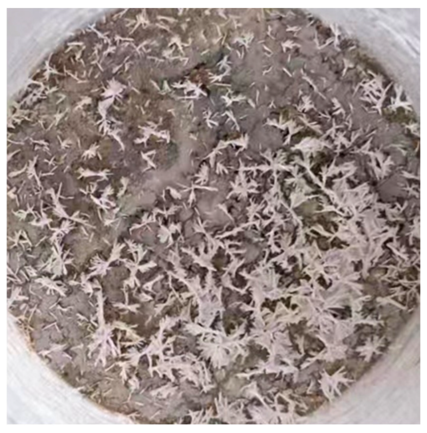
However, field applications have revealed that KSC develops numerous fine white crystalline deposits on its surface after prolonged use. These water-soluble substances, appearing as powdery or flocculent coatings, are collectively termed “efflorescence”. This phenomenon not only compromises the aesthetic integrity of ceramsites but also significantly degrades its mechanical strength due to environmental factors like dehydration or carbonation, leading to structural defects such as cracking and disintegration. Consequently, elucidating the root causes of efflorescence and developing source-control strategies have emerged as critical challenges in the production and application of KSCs.
Efflorescence predominantly occurs in permeable bricks and concrete [
24]. Research indicates that this phenomenon results from the migration and surface crystallization of soluble salts, a process closely correlated with ambient temperature and humidity [
25,
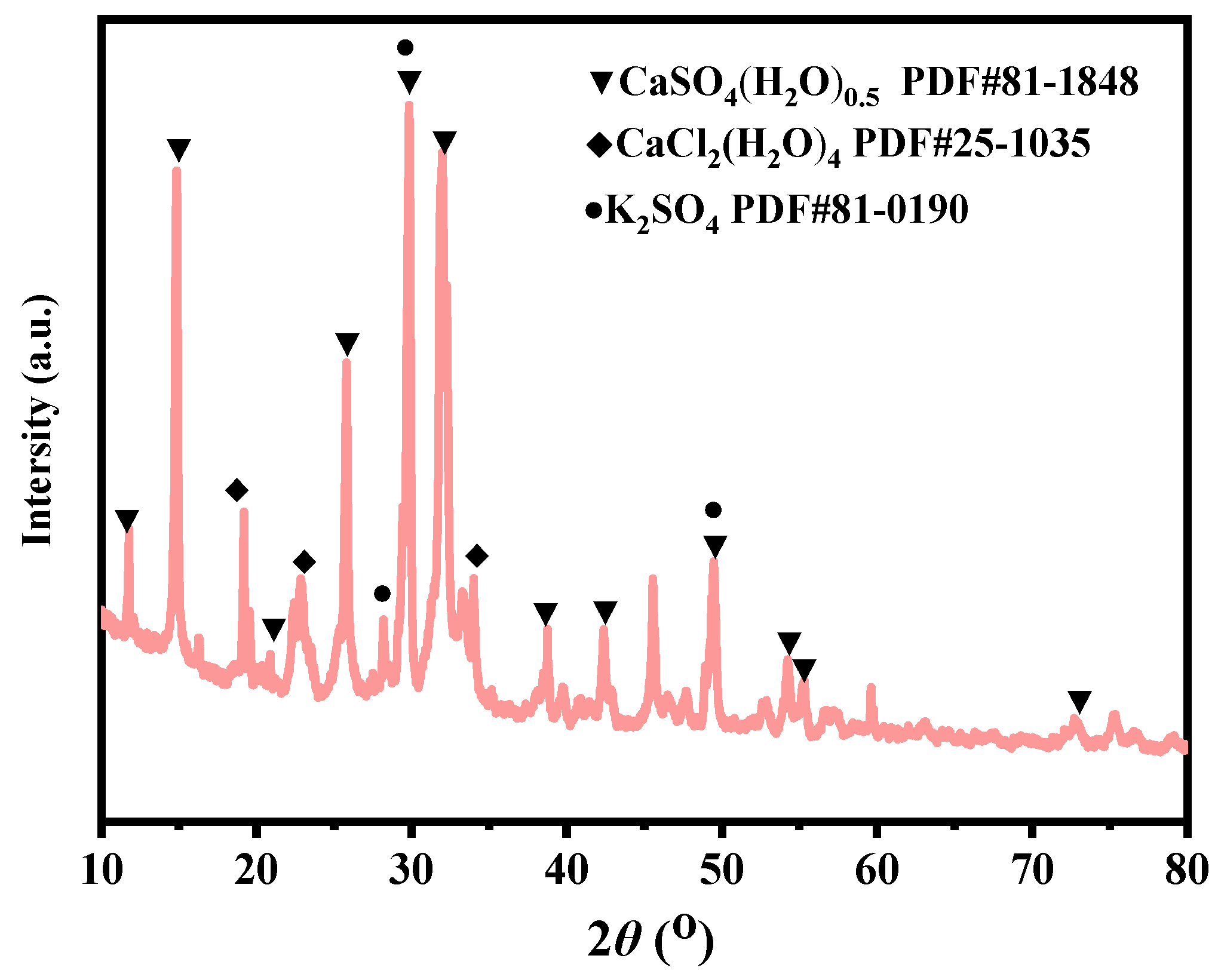
26]. Compositional analysis identifies calcium sulfate (CaSO
4) as the primary component of these white deposits, with potassium sulfate (K
2SO
4) as a secondary constituent [
27,
28]. Further investigations reveal that efflorescence formation requires essential conditions [
29,
30,
31]: soluble salt components in the material composition, porous matrix providing ion migration pathways through capillary pores, water as a transport medium for soluble ions under environmental exposure, and low-temperature, shaded, and continuously cooling conditions that reduce salt solubility and accelerate crystallization.
Efflorescent salts originate from both intrinsic material components and external environmental sources. Internal sources: cement-based materials generate substantial Ca(OH)
2 through hydration reactions, which serves as the main alkaline source for carbonate efflorescence. Aggregates containing soluble alkaline ions such as Na
+ and K
+, as well as unreacted free CaO in admixtures (e.g., fly ash), can act as “salt reservoirs” [
32]. External sources: groundwater, rainwater, or meltwater infiltrate the material via capillary action, carrying erosive ions like Cl
− and SO
42−. Acidic gases such as SO
2 and NO
x in industrial atmospheres react with Ca(OH)
2 on the material surface, forming CaSO
4·2H
2O or Ca(NO
3)
2, further increasing salt diversity and concentration [
33]. Additionally, the porous structure of these materials provides ion migration channels, known as capillary pores. In porous media, moisture moves upward through capillary forces, transporting dissolved salts to the evaporation surface where they accumulate [
34,
35].
Agrawal V et al. [
36] studied the phenomenon of alkali efflorescence in red mud ceramics, where solid-state reactions form Na
2SO
4 between BaSO
4, Na
2Fe
2Ti
6O
16, and NaAlSiO
4 above 1000 °C. The addition of KOH to the mixture reduces Na
2SO
4 generation by reacting with red mud and BaSO
4 to form stable phases of K
3NaS
2O
8 and KAlSiO
4, thereby mitigating efflorescence. Zou S et al. [
37] investigated the effects of steam curing on high-strength slag-based alkali-activated materials. They found that, after 24 h of steam curing, the compressive strength of the alkali-activated materials significantly improved, efflorescence was markedly reduced, and steam curing proved to be an economical, practical, and effective method. Zhang et al. [
38] summarized efflorescence prevention measures for permeable bricks: using low-alkali cement or incorporating pozzolanic materials (e.g., silica fume) to immobilize free Ca
2+ and reduce alkali content; refining pore structures to inhibit salt migration; and applying silicone-based materials to lower surface water absorption via hydrophobic coatings, though durability concerns require attention.
During the fabrication of KSCs, surface efflorescence occasionally occurs under specific environmental conditions, significantly hindering its engineering applications. To address this challenge, a systematic investigation into the causes of efflorescence and preventive strategies during production is imperative for advancing the practical implementation of this material. This study employed a multi-method analytical framework—including X-ray diffraction (XRD), scanning electron microscope (SEM), element analysis (EA), and thermogravimetric-mass spectrometry (TG-MS)—to conduct targeted experiments, evaluating efflorescence susceptibility of ceramsites sintered at 1150 °C, identifying critical environmental triggers for efflorescence during storage, and elucidating the influence of key sintering parameters on efflorescence development. Through this integrated approach, we aim to unravel the fundamental mechanisms of efflorescence in KSCs and establish optimized process control protocols.
2. Materials and Methods
2.1. Preparation of Raw Materials
The raw materials used in this experiment were sourced from Botai Environmental Protection Technology Co. Ltd. in Tangshan, China. The chemical composition and mineral phases of the raw materials were analyzed at room temperature (25 °C) using X-ray fluorescence (XRF, Rigaku ZSX Primus, Tokyo, Japan) and X-ray diffraction (XRD, Rigaku SmartLab 9 kW, Tokyo, Japan).
2.2. Preparation of Basic Experimental Samples
The raw materials were dried and then a ball mill was used to finely grind the mixed raw materials to a powder state. Next, the kiln slag, fly ash, and clay were accurately mixed in a ratio of 60:35:5 by mass. The homogenized mixture was pulverized using a ball mill (DH488-2Z, Beijing, China) and sieved through a 200-mesh screen. The resulting powder was then processed through an extrusion pelletizer (SKJ-320, Jinan, Shandong, China) to form green KSCs pellets with diameters of 10–15 mm and moisture content of 11–13%. These pellets were subsequently dried at 105 °C for 2 h.
The extrusion pelletization mechanism comprises four sequential stages: feeding, extrusion, profiling, and cutting. First, the ball-milled raw material was loaded into the hopper, where spiral blades conveyed it toward the extruder. Next, the extruder compacted and pressurized the material through the rotation of a screw. Subsequently, the material was forced through a die orifice to form continuous strands of the desired shape. Finally, a cutting device segmented the extruded strands into ceramsites pellets with lengths of 10–15 mm.
The dried green KSCs were sintered in a gradient crystallization furnace (GR1300/13, Lilienthal, Berlin, Germany) under controlled thermal conditions. The sintering protocol involved heating at a rate of 300 °C/h to target temperatures (1090 °C, 1110 °C, 1130 °C, 1150 °C, 1170 °C, and 1190 °C), followed by a 15 min holding time at each target temperature. After sintering, the samples were furnace-cooled to room temperature. Water absorption rate measurements were subsequently conducted on the cooled KSCs samples.
The dried green KSCs were loaded into a small-scale sintering kiln (50 kg capacity) and sintered with a heating rate of 10 °C/min. Upon reaching the target sintering temperature of 1150 °C, the samples were held for 15 min, followed by furnace cooling to room temperature. The sintered KSCs samples were then subjected to XRD and carbon–sulfur analysis.
2.3. Efflorescence Test Protocol
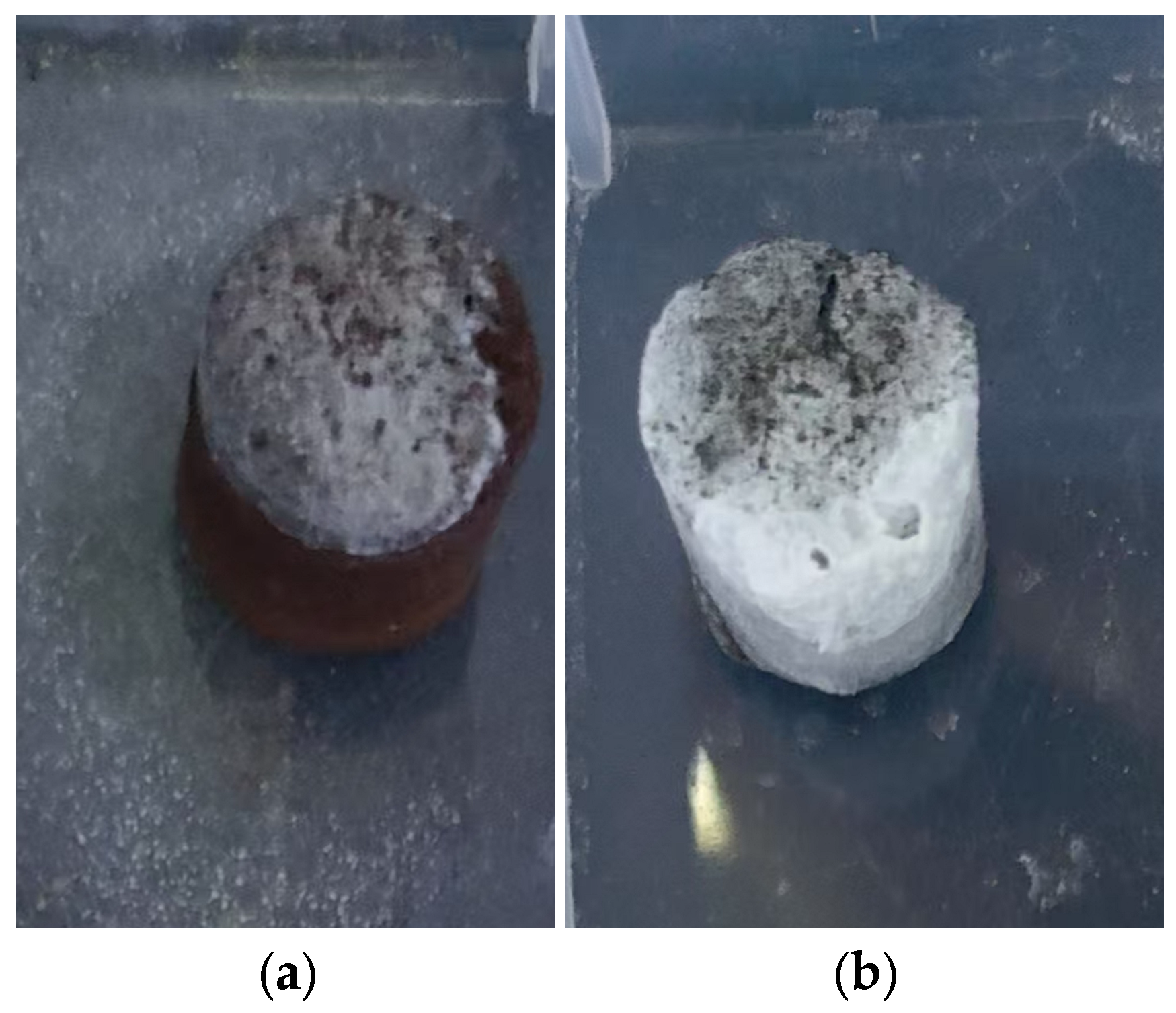
To simulate efflorescence under accelerated humid conditions, half of the KSCs samples were partially immersed in water for 72 h to observe surface alterations. Subsequently, the samples underwent forced-air drying under a ventilation fan. Post-drying visual inspections were conducted to detect efflorescence. The efflorescent deposits (white crystalline substances) on the ceramsites surface were meticulously collected for chemical composition analysis and mineral phase identification via XRD.
2.4. Introduction to Small-Scale Verification Experiment
The experiment was carried out in a small-scale sintering kiln system at Botai Environmental Protection Technology Co. Ltd. Tangshan, China. The sintering furnace system is shown in
Figure 1, which mainly consists of three parts: sintering furnace, dust removal device, and desulfurization device. The dried green KSCs were placed in a beaker inside the sintering furnace B. The detailed structure of the sintering furnace is shown
Figure 1, where 50 kg of KSCs was placed in the beaker inside the sintering furnace, with a beaker height of 300 mm. The bottom was pre-laid with a base material, namely sintered KSCs, to avoid overheating of the perforated grate at the bottom. The upper part of the sintering furnace was a natural gas combustion chamber A, where natural gas entered the combustion chamber for combustion, forming a gas of the set temperature. The gas passed through KSCs in the beaker and was discharged from the bottom of the sintering furnace. It then passed through the dust removal device C and was drawn by an induced draft fan before entering the desulfurization device G for desulfurization and subsequent emission. The concentration of SO
2 and O
2 in the flue gas was measured in the pipeline after the fan outlet and before the flue gas treatment (at point L in
Figure 1).
2.5. Characterization Methods
The thermal behavior and gas emissions of KSCs during the sintering process were analyzed using thermogravimetric–mass spectrometry (TG-MS, Netzsch QMS4range03, Selb, Germany). The thermal analysis was conducted under stable airflow conditions, with a linear heating rate of 10 °C/min. The measurements were performed within a temperature from room temperature (25 °C) to 1000 °C.
A carbon and sulfur analyzer (LECO, CS844, St. Joseph, MI, USA) was used to determine the change in carbon and sulfur content in KSCs at different temperatures. X-ray diffraction analysis (XRD, Rigaku Smartlab 9kw, Tokyo, Japan) was conducted to observe the phase transition of KSCs before and after sintering. The XRD test mode was continuous scanning with a step length of 0.02°, Cu target, scanning rate of 10 (°)/min and 2θ range of 10°~90°. Field emission scanning electron microscopy (FESEM, Zeiss GeminiSEM 300, Oberkochen, Germany) was utilized to analyze the microstructure. The thermodynamic data associated with the reaction equation were calculated using the thermodynamic analysis software Outokumpu HSC Chemistry 6.0: ∆rGmθ (298.15 K), ΔrHmθ (298.15 K), and ΔrSmθ (298.15 K).
4. Discussion
4.1. Analysis of Conditions for Efflorescent Mineral Formation in KSCs
The occurrence of efflorescence in KSCs required both sufficient and necessary conditions; sufficient condition had the presence of soluble salts, while necessary conditions had the existence of migration channels for dissolution. The formation of soluble salts was attributed to the conversion of iron sulfide in the kiln slag into FeS during the sintering process. Calcium in the ceramsites did not combine with silicates but instead reacts with FeS to form CaSO4. Therefore, during the sintering of KSCs, it was necessary to reduce the FeS content. Additionally, since the migration channels in KSCs accelerate the dissolution of salts, the sintering process should enhance densification and reduce the water absorption rate of KSCs.
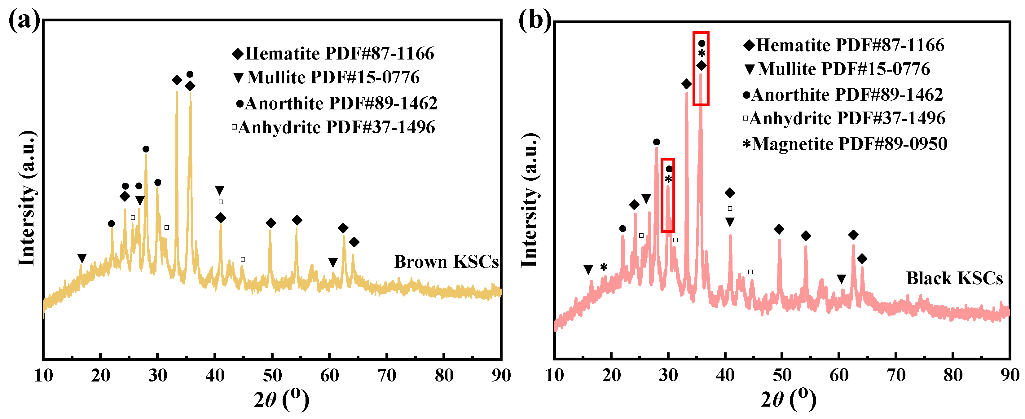
XRD analysis results indicated distinct CaSO4 diffraction peaks in KSCs, confirming the material basis for efflorescence. Higher sulfur content correlated with increased formation of soluble sulfates during sintering, thereby elevating post-service efflorescence risks. During sintering, sulfur reacted with calcium and potassium in raw materials to generate soluble sulfates (e.g., CaSO4). To reduce sulfate content, process optimization must prioritize sulfur volatilization as gaseous SO2 through controlled oxidation. This requires identifying the critical sintering temperature at which sulfur oxidizes to SO2 and extending the duration at this temperature, while simultaneously determining the temperature range where sulfur tends to form sulfates and minimizing the processing time within that range.
The TG-DTG-MS analysis spectrum of KSCs is shown in the
Figure 9, revealing the release patterns of volatile components in KSCs at various stages. Below 200 °C, the TG curve declined, with an endothermic peak observed at 140 °C.
Figure 9b1 indicates that the mass loss during this stage corresponds to the volatilization of bound water in the sample. The fastest desulfurization phase occurred between 485 and 600 °C, where the MS curve demonstrated the release of SO
2 and CO
2 gases within the 450–600 °C temperature range. The oxidative combustion reaction of FeS occurring within the temperature region of 400–600 °C produced Fe
2O
3 and SO
2. Among them, iron oxide (primarily Fe
2O
3 and Fe
3O
4) was the main product of pyrite oxidation. Therefore, reaction Equations (1)–(3) were as follows:
At this point, KSCs entered a rapid oxidation-combustion stage, during which C was oxidized to CO
2 and FeS was oxidized to SO
2. In the 600–800 °C range, the MS curve revealed that this stage was dominated by the oxidation of C to CO
2. Beyond 800 °C, the oxidation of carbon was nearly complete. However, minimal sulfur oxidation was observed between 600 and 1000 °C. Based on the TG-DTG-DSC curves in
Figure 9 and the XRD patterns in
Figure 4, it can be observed that CaSO
4 was formed within the temperature region of 600–800 °C in KSCs. A second desulfurization phase emerged within 1000–1150 °C, as evidenced by the rising SO
2 gas released curve in the MS curve starting at 1000 °C. Therefore, reaction Equations (4)–(6) were as follows:
By combining Equations (2) and (4), we obtain the sulfation reaction as Equation (5). When CaO and FeS were present during the sulfation reaction in Equation (5), the main factors influencing it from a thermodynamic perspective were temperature and O
2 concentration. The Gibbs function for the forward reaction in Equation (7) of sulfation was:
Gibbs free energy Δ
G was defined as Δ
G = ΔH−TΔS, and the thermodynamic data in
Table 4 can derive the Gibbs function for the forward reaction as Equation (8) of sulfation Equation (5):
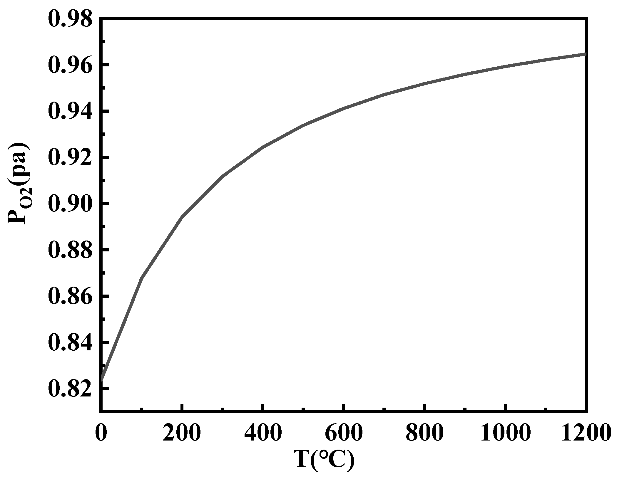
As can be seen from
Figure 10, as the temperature increased, the P
O2 rapidly increased when Δ
G3 was zero. This could also be understood as the easier decomposition of calcium sulfate at higher temperatures, necessitating a higher concentration of oxygen to maintain the forward reaction. This further demonstrated that the primary reason for the occurrence of sulfation reactions was the presence of high CaO content in the KSCs, followed by the completion of carbon oxidation to carbon dioxide during the sintering process at 600–800 °C, which enhanced the oxidizing atmosphere.
The results indicated that SO2 was released within two temperature ranges: 450–600 °C and 1000–1150 °C. Between these temperature ranges, a sulfur fixation reaction occurred, where CaO in KSCs reacted with the released SO2 to form CaSO4, leading to the formation of new sulfur-containing compounds (e.g., sulfates) within KSCs. To reduce the internal sulfur content of KSCs, the sintering process should prolong the duration within these two desulfurization temperature ranges to ensure thorough release of SO2, thereby minimizing sulfur retention in the final product.
4.2. Effect of Sintering Process on the Efflorescence of KSCs
The occurrence of efflorescence in KSCs required the presence of leaching channels within the ceramsites structure. To mitigate this, it was critical to identify the densification temperature of KSCs, enhance its degree of densification, and reduce its water absorption rate. Uneven temperature and atmosphere distribution within the sintering furnace arose due to the exothermic oxidation of FeS during the sintering process. This reaction caused a rapid temperature spike in the central zone of the furnace, accompanied by a sharp decline in oxidative conditions.
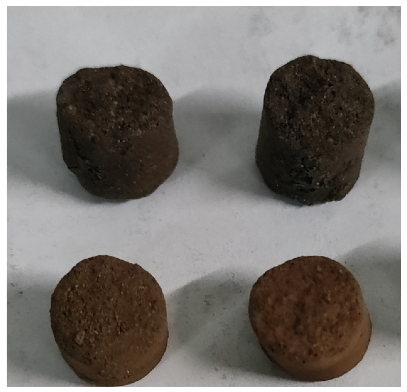
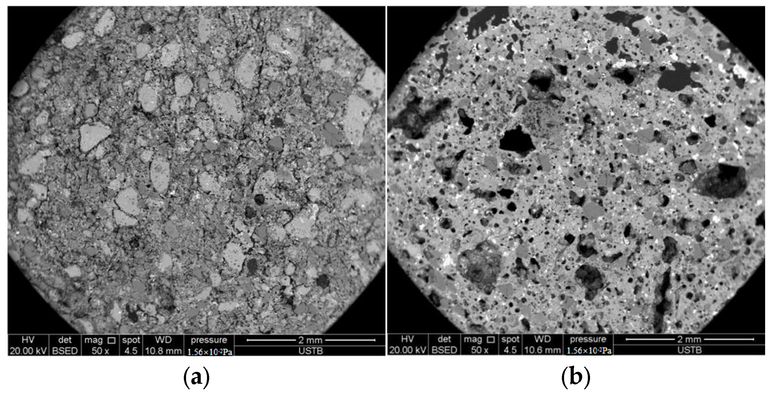
According to carbon and sulfur testing results, the black KSCs exhibited higher carbon and sulfur content compared to the brown samples. Experimental results revealed that the black KSCs displayed more severe efflorescence than the brown KSCs. SEM observations indicated that the brown KSCs had a dense internal structure with no significant voids, whereas the black high-sulfur KSCs exhibited a porous structure. This was attributed to the reaction of FeS forming Fe3O4 during the densification of the black KSCs. The internally generated SO2 was not fully released, causing carbon and sulfur to become trapped in the liquid phase. These elements subsequently formed sulfates within the ceramsites, leading to the development of numerous internal pores.
For the brown KSCs, although it was located near the furnace wall and experienced slower heating rates, CaSO4 did not reach its decomposition temperature during the final sintering stage. As a result, sulfur was not sufficiently released and remained trapped within the material.
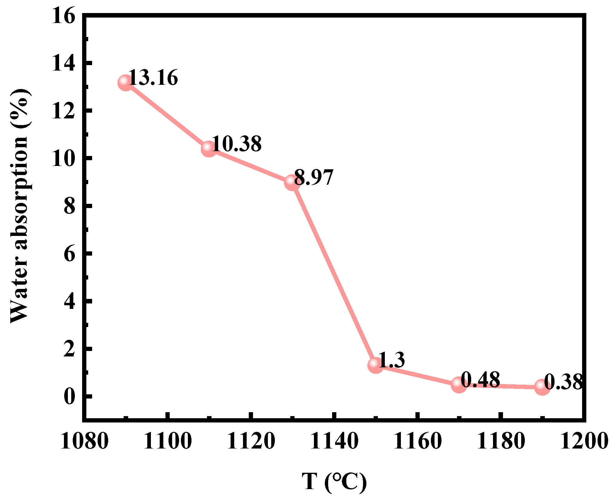
Wang et al. [
6] demonstrated in their analysis of ceramsites production using zinc-extraction kiln slag that 1050–1180 °C was the critical temperature range for ceramsites densification. As shown in
Figure 11, the water absorption of KSCs sintered at 1090–1190 °C rapidly decreased within the 1130–1150 °C interval, indicating active densification. Therefore, during the ceramsites sintering process, precise temperature control was critical. The oxidation of FeS within the ceramsites must be fully completed before raising the temperature to the 1130–1150 °C range.
During sintering, it was essential to avoid rapid heating rates that could trap SO2—released from CaSO4 decomposition—inside the ceramsites due to premature densification, ensuring the final sintering temperature was reached to prevent residual sulfur (S) retention caused by insufficient decomposition of CaSO4.
To optimize the sintering parameters for KSCs, the following adjustments were critical. The desulfurization duration in the low-temperature stage (e.g., 450–600 °C) was prolonged and the oxidative atmosphere enhanced during this phase to ensure complete oxidation and decomposition of FeS in KSCs, thereby fully releasing SO2. The high-temperature sintering time (e.g., 1000–1150 °C) was extended while reducing the oxidative atmosphere in this stage to accelerate the decomposition of CaSO4, facilitating the release of additional SO2. This dual strategy reduced the soluble salt content (e.g., CaSO4) within the ceramsites, effectively suppressing efflorescence by minimizing residual sulfates.
Based on the above analysis, the sintering parameters for KSCs were optimized as follows. Low-temperature stage (400–600 °C): a 15 min holding time with enhanced oxidative atmosphere to ensure complete oxidation of FeS and SO2 release. High-temperature stage (1000–1100 °C): a 15 min holding time with reduced oxidative atmosphere to promote CaSO4 decomposition and minimize sulfate retention. After re-sintering 50 kg of KSCs under these conditions, post-test results showed a water absorption rate of 1.2% and a sulfur content of 0.72%, indicating a significant reduction in sulfur retention compared to previous batches.
5. Conclusions
This study investigated the inhibition mechanism of efflorescence in high-sulfur KSCs. Through 50 kg scale sintering experiments, a novel process strategy for efflorescence control was developed. Conclusions were as follows:
1. The mechanism of efflorescence in KSCs required both sufficient and necessary conditions; sufficient conditions had the presence of soluble salts CaSO4, while necessary conditions had the existence of migration channels for dissolution. High-sulfur kiln slag inherently contained elevated sulfur content (4.53%) and alkaline substances such as CaSO4. The porous structure of ceramsites (ceramsites exhibiting a water absorption rate of 8.5%) exacerbated the efflorescence phenomenon.
2. The formation of soluble CaSO4 in KSCs was revealed and a novel sintering process to reduce sulfur was proposed. During the sintering process, the desulfurization duration was extended and meantime the oxidative atmosphere at the low-temperature period was enhanced, ensuring enough oxidation of FeS to release more SO2 in ceramsites. Simultaneously, the high-temperature sintering period was prolonged while reducing the oxidative atmosphere during this phase to accelerate the decomposition of CaSO4 to release SO2 gas. These strategies effectively reduced soluble calcium sulfate content in ceramsites, thus suppressing the efflorescence phenomenon.
3. Another effective method to enhance the sintered densification of ceramsites was to change the mineral phase. The Fe3O4 formed in KSCs lowered the densification temperature, causing SO2 gas released from decomposed CaSO4 to be trapped within the ceramsites due to premature densification before escaping into the atmosphere. This results in the formation of multiple internal voids. By maintaining the KSCs in an oxidizing atmosphere at 400–600 °C for 15 min followed by a reducing atmosphere at 1000–1100 °C for 15 min prior to its densification temperature, more Fe2O3 and less Fe3O4 formed in ceramics, resulting in an increasing sintering temperature, and sulfur inside the ceramsites was fully released. This process promoted uniform internal densification of the ceramsites, resulting in a reduction in its water absorption rate from 8.5% to 1.2%. Additionally, the efflorescence phenomenon of the ceramsites was significantly alleviated.


