Article

Influence of Rotational Speed on the Microstructure and Mechanical Properties of Refill Friction Stir Spot Welded Pure Copper

1
Department of Materials Science, National Technical University “Kharkiv Polytechnic Institute”, 61002 Kharkiv, Ukraine
2
College of Mechanical and Electrical Engineering, Huangshan University, Huangshan 245041, China
*
Author to whom correspondence should be addressed.
Crystals 2025, 15(3), 268; https://doi.org/10.3390/cryst15030268
Submission received: 18 February 2025 / Revised: 8 March 2025 / Accepted: 11 March 2025 / Published: 13 March 2025

Abstract

:
Refill friction stir spot welding (RFSSW) is an effective technique for achieving high-quality joints in metallic materials, with rotational speed being a critical parameter influencing joint quality. Current research on RFSSW has primarily focused on low-melting-point materials such as aluminum alloys, while limited attention has been given to pure copper, a material characterized by its high-melting-point and high-thermal-conductivity. This study aims to investigate the effects of rotational speed on the microstructure and mechanical properties of RFSSW joints in pure copper. To achieve this goal, welding experiments were conducted at five rotational speeds. The welding defects, microstructure, and hook morphology of the welded joints were analyzed, while the variations in axial force and torque during welding were studied. The influence of rotational speed on the microhardness and tensile-shear failure load of the welded joints was explored, and the fracture modes of the welded joints at different rotational speeds were discussed. The results indicated that the primary welding defects were incomplete refill and surface unevenness. Higher rotational speeds resulted in coarser microstructures in the stir zones. As the rotational speed increased, the hook height progressively rose, the peak axial force showed an increasing trend, and the peak torque continuously decreased. The high microhardness points in the welded joints were predominantly located at the top of the sleeve stir zone (S-Zone), while the low microhardness points were observed at the center of the pin stir zone (P-Zone) and in the heat-affected zone (HAZ). The tensile-shear failure load of the welded joints initially increased and then decreased on the whole with the rising rotational speed, peaking at 5229 N at a rotational speed of 1200 rpm. At lower rotational speeds, the fracture type of the welded joints was characterized as plug fracture. Within the rotational speed range of 1200 rpm to 1600 rpm, the fracture type transitioned to upper sheet fracture. The initial fractures under different rotational speeds exhibited ductile fracture. This study contributes to advancing the understanding of RFSSW characteristics in high-melting-point and high-thermal-conductivity materials.

1. Introduction

Pure copper possesses excellent electrical conductivity, thermal conductivity, and ductility, making it widely used in automotive manufacturing, aerospace, and power electronics applications, such as copper busbars in new energy vehicles, conductive strips, and heat exchangers [1,2,3]. To meet the processing, installation, and diversified usage demands in industrial applications, pure copper is often fabricated into copper sheets. The thin profile of pure copper sheets enhances efficiency in electrical and thermal applications. In practical scenarios, permanent and stable connections between pure copper sheets are often required to ensure consistent electrical conductivity or thermal conductivity. Traditional pure copper sheet joining methods include fusion welding, brazing, resistance spot welding, and mechanical joining [4]. While fusion welding can produce strong joints, it often results in thermal cracking and grain coarsening of the copper at high temperatures, which compromises the load-bearing capacity of the joints [5]. Brazing avoids overheating of the base material but yields joints with relatively low strength, and the selection and application of brazing filler materials are complex. Resistance spot welding entails high equipment costs, rapid electrode wear, and susceptibility to thermal cracking [6,7,8]. Mechanical joining methods, such as bolting and riveting, circumvent the thermal impact on material properties but have low joining efficiency and demand significant space for the joining area, making them unsuitable for narrow space conditions [9,10]. Friction stir spot welding (FSSW), as a local solid-state joining technique, offers a novel solution for locally joining pure copper due to its advantages of low heat input, avoidance of melting, excellent joint properties, absence of filler materials, and no pollutant emissions [11,12,13,14]. Derived from friction stir welding [15], FSSW was first applied in the body manufacturing of Mazda Motor Corporation in 2003 [6]. In FSSW, a rotating tool penetrates the workpieces to be welded, generating heat through friction to locally soften the material in the welding area. The mechanical stirring action of the tool induces plastic material flow, mixing the material in the welding area to complete the joint in the solid state. However, due to the unique tool movement, conventional FSSW leaves a keyhole defect in the welding zone after completion, which compromises joint integrity and significantly weakens the load-bearing capacity of the welded joint [16,17]. To enhance the load-bearing capacity of welded joints, researchers have introduced swept friction stir spot welding (SFSSW) [18]. SFSSW is an advancement of conventional FSSW, incorporating additional tool motions in the transverse and circumferential directions. These supplementary movements increase the welding area, thereby effectively improving the load-bearing capacity of the welded joints. However, keyhole defects remain a persistent issue after welding [19,20]. To address this limitation, the pinless friction stir spot welding (PFSSW) was proposed. PFSSW employs a high-speed rotating pinless tool, which penetrates the workpieces to be joined. The mechanical stirring action of the tool facilitates material mixing, enabling the welding of the upper and lower sheets [21,22,23,24]. While PFSSW successfully eliminates keyhole defects, it results in a reduction in the thickness of the welding zone, thereby limiting the load-bearing capacity of the welded joints. Consequently, this technique is primarily suited for the joining of thin sheets. To further enhance welding strength and joint integrity, the GKSS Research Center (Helmholtz-Zentrum Geesthacht) in Germany developed refill friction stir spot welding (RFSSW) [25]. RFSSW employs a distinctive combination of tools and motion patterns, significantly improving joint integrity, eliminating keyhole defects, and increasing the load-bearing capacity of the welded joints [26]. RFSSW is regarded as one of the most promising local solid-state joining technologies for large-scale applications [27,28,29].
Current research on RFSSW primarily focuses on the effects of welding process parameters on the microstructure and mechanical properties of welded joints [30,31,32,33]. Existing studies have demonstrated that rotational speed, as a critical welding parameter, significantly influences the heat input and material flow behavior in the welding zone, thereby determining the microstructure and mechanical performance of the welded joints [34,35,36,37]. The impact of rotational speed on joint strength varies depending on the material type and plate thickness. For aluminum alloys such as 2A12, 2198, 2219, and 6061, the tensile-shear failure load of the welded joints initially increases and then decreases with increasing rotational speed [38,39,40,41]. In contrast, for the 2024 aluminum alloy, the tensile-shear failure load decreases continuously as rotational speed increases, likely due to a reduction in ligament thickness and grain coarsening at elevated temperatures [42]. Liu et al. investigated the influence of rotational speed on the characteristics of RFSSW joints for 1 mm thick AZ31 magnesium alloy and explored the fracture modes under different process parameters [30]. The study revealed that at low rotational speeds, the joint strength was low, and fractures occurred at the interface between the upper and lower sheets, exhibiting shear fracture characteristics. As rotational speed increased, the joint strength improved, and the fracture mode transitioned to shear-plug fracture. Furthermore, Nan et al. studied the effects of rotational speed on the microstructure and mechanical properties of Al/Ti dissimilar material joints, analyzing microstructural variations and failure mechanisms at different rotational speeds. Their findings showed that the joint strength increased with rotational speed, reaching a maximum at 1300 rpm, before declining at higher speeds [43]. Cui et al. conducted RFSSW research on Al/Li alloys, analyzing the effects of rotational speed and welding duration on the microstructure and mechanical properties of the joints. The study showed that the tensile-shear failure load increased with rotational speed. However, excessive heat input exacerbated grain coarsening in the stir zone, negatively impacting joint quality [44]. In addition, Kluz et al. optimized the welding process parameters for 1.6/0.8 mm thick 7075 aluminum alloy using a weighted rank-based optimization approach. Their research indicated that excessively high rotational speeds and prolonged welding times adversely affected the microstructure of the joints, reducing bonding strength [45]. Xiong et al. developed a 3D thermomechanical coupled numerical simulation model of RFSSW for 2 mm thick 2524 aluminum alloy using Abaqus software, focusing on the effects of rotational speed on temperature and stress distribution [46]. The study revealed a W-shaped temperature distribution in the welded joints, with temperatures decreasing from the top to the bottom of the weld due to the superior heat dissipation of the lower sheet. Stress distribution was found to be symmetric, with lower stress at the joint center and maximum stress at the edges of the welding zone, attributed to severe plastic deformation and stress concentration caused by high temperatures in the sleeve zone. As rotational speed increased, material plastic deformation intensified, leading to a decrease in average stress in the welding zone. Moreover, Ji et al. employed Fluent software to investigate material flow behavior during RFSSW of LY12 aluminum alloy. The study indicated that the maximum material flow velocity occurred at the outer wall of the sleeve, with decreasing velocities observed farther from the sleeve wall. Increasing rotational speed was identified as the most effective method to enhance material flow velocity [47].
The above analysis highlights the critical influence of rotational speed on the characteristics of RFSSW joints and reveals significant differences in mechanical properties across different materials under varying rotational speeds. Most existing studies on RFSSW focus on low-melting-point materials such as aluminum and magnesium alloys, whereas research on high-melting-point, high-thermal-conductivity materials like pure copper remains limited. In particular, the mechanisms governing the microstructural evolution and the influence of rotational speed on the mechanical properties of pure copper during RFSSW remain inadequately understood. To bridge the knowledge gap in understanding the joint characteristics of high-melting-point and high-thermal-conductivity materials in RFSSW, this study investigates the RFSSW of pure copper, with a specific focus on elucidating the effects of rotational speed on the microstructure and mechanical properties of welded joints—an aspect that remains insufficiently addressed in existing research. Five welding experiments were conducted at different rotational speeds to achieve this goal. The study examined the appearance of welded joints, welding defects, and hook features, analyzed microstructural differences across various zones, and evaluated the variations in axial force and torque during the welding process. Additionally, the microhardness and tensile properties of the welded joints were assessed, and the fracture mechanisms of the welded joints were discussed. The findings of this study contribute to a deeper understanding of the mechanisms by which rotational speed influences the microstructure and mechanical properties of pure copper RFSSW joints. This work enhances the application scope of RFSSW, providing scientific guidance for the industrial application of RFSSW in pure copper.

2. Materials and Methods

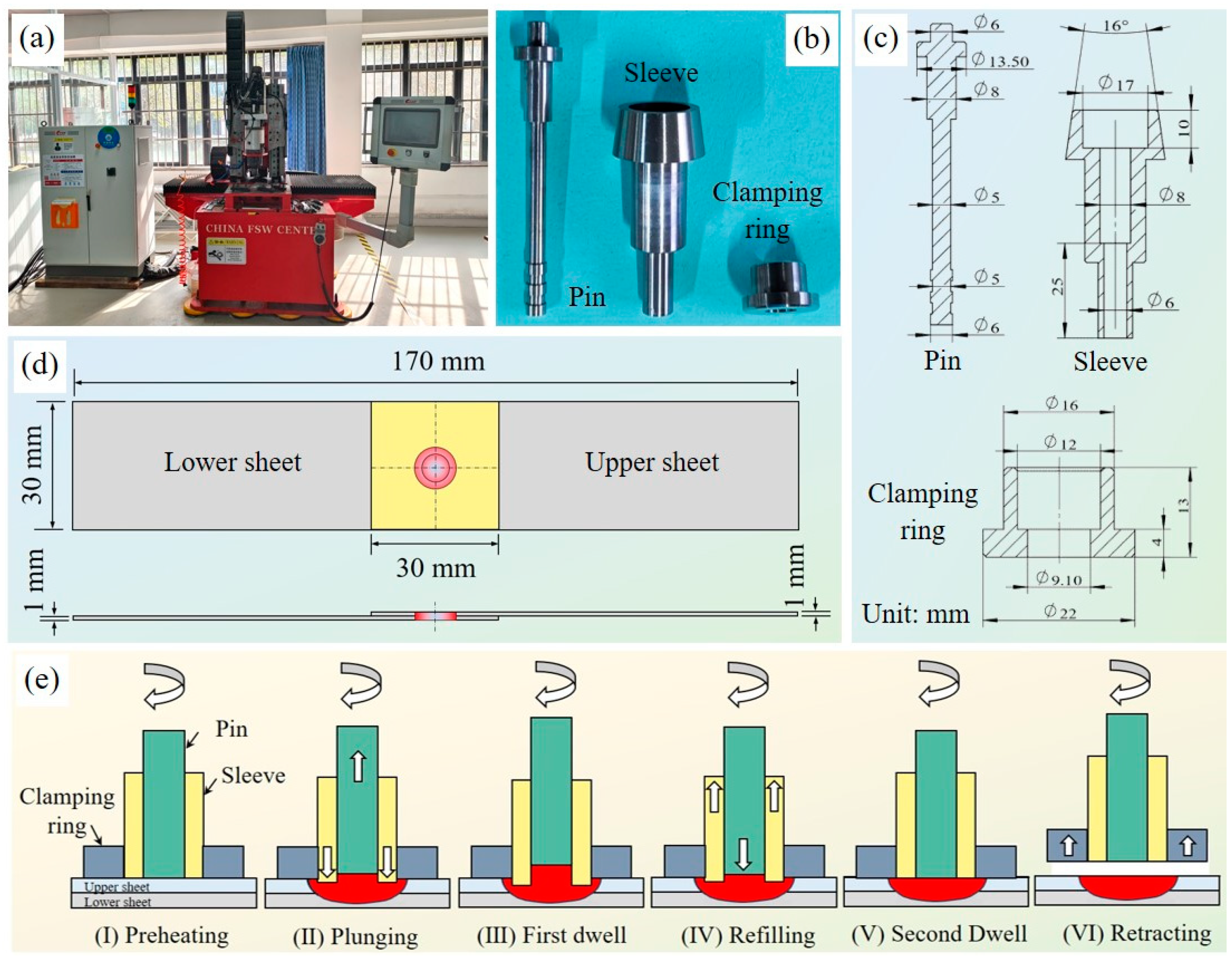
2.1. Experimental Materials and Equipment

The experimental material consisted of T2 pure copper sheets with a thickness of 1 mm, a length of 100 mm, and a width of 30 mm. The chemical composition of the pure copper sheets (wt.%) was as follows: Cu + Ag: 99.90, Bi: 0.001, Sb: 0.002, As: 0.002, Fe: 0.005, Pb: 0.005, S: 0.005, and impurities: 0.08. The welding experiments were conducted using an FSW-TS-DH04 desktop RFSSW machine manufactured by the China FSW Center. Given the high welding temperatures of copper sheets, SKH-9 high-speed steel, known for its excellent high-temperature resistance and wear resistance, was used to fabricate the welding tools. The pin diameter was 6 mm, the inner and outer diameters of the sleeve were 6 mm and 9 mm, respectively, and the inner and outer diameters of the clamping ring were 9 mm and 22 mm, respectively. The welding equipment, tools, and lap dimensions of the copper plates are shown in Figure 1. Figure 1e illustrates the working principle of RFSSW. The RFSSW process consists of several key stages, including preheating, plunging, dwell, refilling, and retracting. The primary purpose of the preheating stage is to utilize frictional heat to soften the local material, facilitating the plunging of the sleeve. During the plunging stage, the sleeve moves axially into the workpiece while the pin retracts upward, creating space for the upward material flow in the stirred zone. Once the sleeve reaches the predetermined depth, it remains dwell for a certain period (first dwell stage) to further soften the material under elevated temperatures and promote material mixing. Subsequently, in the refilling stage, the sleeve retracts upward while the pin plunges downward, pushing the stirred material into the cavity left by the sleeve’s movement. After refilling is completed, a second dwell stage follows, where the tool briefly remains in position to ensure a smoother weld surface. Finally, the tool assembly retracts completely from the workpiece, completing the welding process. During the welding process, the axial force and torque were measured using a self-made octagonal ring dynamometer. The preheating time was set to 3 s, the tool plunging depth to 1.2 mm, the plunging rate to 0.5 mm/s, and the dwell time to 2 s. To ensure a smooth surface quality of the welded joints, the tool remained on the surface of the workpiece for 3 s after material refilling was completed. The clamping force of the clamping ring was set to 7000 N. The selected range of rotation speed was determined based on preliminary experiments. In preliminary experiments, it was observed that 800 rpm was the minimum threshold for achieving a relatively good welding effect. However, when the rotational speed exceeded 1600 rpm, the welding temperature became excessively high, causing the tool to easily stick to the workpiece and deform it during retraction. Additionally, the tool experienced rapid failure due to the high temperatures. To explore the variations in welding joints across a broader range of rotational speeds, welding experiments were primarily conducted at rotational speeds of 800 rpm, 1000 rpm, 1200 rpm, 1400 rpm, and 1600 rpm.

2.2. Microstructure and Mechanical Properties Characterization

To facilitate observation and testing of the internal microstructure and microhardness of the welded joints, the specimens were cut along the width direction at the center of the welding joint using a wire cutting machine. For the cross-sectional microstructure and microhardness test specimens, the dimensions were 22 mm in length, 2.2 mm in width, and 2 mm in thickness. For the surface microhardness test specimens, both the length and width were 22 mm, with a thickness of 2 mm. The cut metallographic specimens were sequentially polished with 320#, 600#, and 1000# sandpapers, followed by electrolytic polishing using an EP-06X electrolytic polishing corrosion device produced by Naibo Testing Technology (Shanghai) Co., Ltd. (Shanghai, China). The polishing solution consisted of a mixture of nitric acid and methanol in a volume ratio of 1:4. The electrolytic polishing was conducted with a voltage of 30 V, a current of 1 A, and a duration of 12 s, based on a surface area of 44 mm2 (22 × 2 mm) exposed to the polishing solution. The polished surface was etched using a ferric chloride hydrochloric acid aqueous solution for approximately 12 s. The microstructure of the etched surface was observed using an YP710TR metallographic microscope produced by Suzhou Yueshi Precision Instrument Co., Ltd. (Suzhou, China). The grinding and electrolytic polishing processes for Electron Backscatter Diffraction (EBSD) test specimens were identical to those for metallographic specimens. EBSD testing was performed using a Hitachi SU8600 scanning electron microscope (Hitachi High-Tech, Tokyo, Japan) equipped with an Oxford Instruments (Abingdon, UK) detector. The fracture morphology of the welded joints was also observed using the SU8600 scanning electron microscope.
For microhardness testing, the specimens were first embedded and then sequentially polished with 320#, 600#, and 1000# sandpapers, followed by polishing with a MDS600 metallographic polishing machine produced by Shanghai Caikang Optical Instrument Co., Ltd. (Shanghai, China). The abrasive used was an artificial diamond grinding paste with a particle size of W 0.5 produced by Shanghai Flash Hardware Abrasive Factory. A HRS-150T Vickers microhardness tester produced by Laizhou Hengyi Testing Instrument Co., Ltd. (Yantai, China) was employed to measure the surface and cross-sectional microhardness of the welded joints, with the load and dwell time set to 300 g and 10 s, respectively. In the surface microhardness cloud map, 30 rows and 30 columns of points were tested with a horizontal and vertical spacing of 0.5 mm between points. In the cross-sectional microhardness line map, two rows of microhardness values were measured at the center of the upper sheet (Line 1) and the lower sheet (Line 2), with a spacing of 0.3 mm between points in each row. In the cross-sectional microhardness cloud map, seven rows of data were obtained, each containing 63 test points with a horizontal spacing of 0.3 mm between points and a vertical spacing of 0.25 mm between rows. The contour plot tool in Origin (Version 2017) software was utilized to visualize the distribution of microhardness on both the cross-section and the surface. The coordinate origin of the surface microhardness cloud map was set at the center of the welded joint, while the origin of the cross-sectional microhardness cloud map was positioned at the bottommost point of the joint center.
The tensile tests were conducted on a UTM-1432 universal tensile testing machine produced by Chengde Jinjian Testing Instrument Co., Ltd. (Chengde, China) at a tensile rate of 0.025 mm/s to evaluate the tensile-shear performance of the welded joints. The maximum load-bearing capacity of the tensile testing machine is 20 kN. The tensile test standard followed the Chinese National Standard GB/T 3355-2014 [48]. The dimensions of the tensile specimens are shown in Figure 1d. It should be noted that, unlike friction stir welding, the maximum tensile-shear force was commonly used as the representative parameter for joint strength in the field of RFSSW [49,50], without considering the elongation during the tensile process. Therefore, the elongation of the specimen was not taken into account during tensile testing. To enhance the accuracy and reliability of the results, two specimens were tested for each rotational speed, and the average value was reported as the final result. The residual stress on the surface of the welded joints was measured using an LXRD residual stress tester manufactured by Proto. Measurements were conducted along the width direction at the center of the welded joint surface, with a spacing of 0.5 mm between test points.

3. Results and Discussion

3.1. Appearance and Defects

Figure 2 illustrates the surface appearance and typical defects of the welded joints at different rotational speeds. As shown in Figure 2a,b, the surfaces of the welded joints are relatively smooth across all rotational speeds, with the welding zones exhibiting good forming quality. The welding zone comprises two distinct zones: the pin stir zone (P-Zone) and the sleeve stir zone (S-Zone). Clear boundaries are observed between the P-Zone and the S-Zone, as well as between the S-Zone and the non-welded zone, as depicted in Figure 2b. Within the range of rotational speeds investigated, two primary types of defects were identified: incomplete refill and surface unevenness, as shown in Figure 2c,d. Incomplete refill defects predominantly occurred at 800 rpm, where the low rotational speed resulted in insufficient frictional heat, leading to reduced material flow [51]. Consequently, annular groove defects formed at the boundary of the S-Zone on the upper surface of the welded joints due to incomplete material refill. The presence of incomplete refill and surface unevenness defects compromises the integrity of the welded joints and adversely affects their strength. Increasing the rotational speed or allowing the tool to achieve thermal equilibrium through continuous multi-point welding significantly reduced the occurrence of incomplete refill defects. Surface unevenness defects arose when the alignment between the pin and sleeve bottoms was not properly adjusted, creating a pronounced height difference between the P-Zone and the S-Zone. In Figure 2d, since the bottom surface of the sleeve is lower than that of the pin, the material in the S-zone experiences more intense pressure during welding, causing more material to be displaced toward P-Zone and the outer region of S-Zone. This results in the formation of curved flow trajectories at both ends of the S-Zone. Moreover, at the bottom ends of the P-Zone, nearly vertical dark lines are observed. These features are attributed to the stepwise accumulation of material during the refilling process. Given the relatively high position of the pin, the downward pressure exerted during refilling is relatively low, which limits the lateral displacement of the material within the P-Zone, thereby forming nearly vertical trajectory lines. The occurrence of surface unevenness defect is unrelated to rotational speed. This defect can be eliminated by adjusting the relative position between the pin and sleeve.

3.2. Microstructure

Figure 3 presents the cross-sectional macrostructure of the welded joints at different rotational speeds. Unlike conventional FSSW, RFSSW features two stir zones: the S-Zone and the P-Zone [52]. Outside the boundary of the S-Zone are the thermo-mechanically affected zone (TMAZ) and the heat-affected zone (HAZ). Additionally, in the central part of the S-Zone, pronounced material flow induced by the sleeve’s stirring action imparts TMAZ characteristics to this zone. At the bottom of the P-Zone, mechanical stirring is limited, and the material is primarily subjected to high temperatures during the welding process, resulting in the formation of a HAZ in this zone. From the figure, a distinct interface is visible between the upper and lower sheets within the welding zone, referred to as the bonding ligament. The bonding ligament is generally considered a transitional structure between zones of incomplete mixing or bonding and fully bonded areas in the welded joint [53]. Its formation is closely associated with the plastic flow of material between the upper and lower sheets [30]. At different rotational speeds, the bonding ligament exhibits a W-shaped morphology with variations in bending degree. At 800 rpm, the bonding ligament is located farther from the bottom of the lower sheet, at a distance of 1.03 mm. As the rotational speed increases, this distance tends to decrease, reaching 0.85 mm at 1600 rpm. This phenomenon occurs because higher rotational speeds result in increased welding temperatures, which enhance material flowability. The intensified mechanical stirring of the tool expands the stir zone’s range. Furthermore, at higher rotational speeds, the TMAZ formed within the S-Zone becomes more pronounced, primarily due to elevated temperatures enhancing material flow within the S-Zone.
Figure 4 illustrates the microstructure at zone ① under different rotational speeds. It is evident that as the rotational speed increases, the microstructure in zone ① exhibits a coarsening trend. This is primarily attributed to the increased frictional heat at higher rotational speeds, where greater heat input promotes grain growth within the microstructure.
To elucidate the microstructural differences in various zones of the welded joint, EBSD analysis was conducted on zones ①, ②, ③, and ④ under a rotational speed of 1200 rpm, as shown in Figure 5. Zone ① is located at the central position above the bonding ligament in the P-Zone. Zone ② is positioned in the upper part of the S-Zone, while zone ③ is situated at the outer boundary of the S-Zone. Zone ④ is located in the TMAZ beneath the S-Zone. The specific locations of zones ①, ②, ③, and ④ are marked in Figure 3.
Figure 5(a1) shows that the base material exhibits relatively fine grains, with an average grain size of 2.55 μm. The substructured grains constitute the highest proportion in the base material, accounting for 84.99%, followed by recrystallized grains at 12.92%, while deformed grains have the lowest fraction at only 2.09%, as shown in Figure 5(a2). Figure 5b–e show that the grain size varies across different zones of the welded joint. Zone ① exhibits the coarsest grains, with an average grain size of 8.54 μm, which is 3.35 times that of the base material. In contrast, Zone ② has slightly finer grains, with an average grain size of 6.25 μm, which is 2.45 times that of the base material. Notably, Zone ③ exhibits significant grain size variation: the grains of HAZ on the right of the boundary are relatively coarse, whereas those in the TMAZ are the finest, with an average grain size of 4.21 μm, which is smaller than that in Zones ① and ②, as shown in Figure 5d. In Zone ④, a pronounced elongation of grains due to material flow is observed, with the largest grain size reaching 49.08 μm, as shown in Figure 5e. From the DRX maps, it is evident that substructured grains remain predominant in the welded zones. Zone ① exhibits the highest fraction of substructured grains at 87.02%, slightly exceeding that of the base material. Compared with the base material and Zone ①, the proportions of substructured grains in Zones ②, ③, and ④ decrease to varying degrees, while the fraction of deformed grains significantly increases. Among these Zones, Zone ③ exhibits the highest proportion of deformed grains at 30.59%, primarily distributed in the TMAZ and S-Zone.
The variations in grain size and grain types across different zones are closely related to the thermomechanical coupling effect experienced during the welding process. Zone ① is located near the center of the welded joint, where mechanical stirring by the tool is relatively limited. However, this zone experiences elevated temperatures during welding [46], where the thermal effect dominates over the mechanical stirring, thereby facilitating grain growth and promoting the formation of substructured grains. In Zone ②, the material undergoes intense plastic deformation due to the high linear velocity of the tool. Simultaneously, the elevated temperature softens the material, leading to grain fragmentation and the formation of finer grains. The intense mechanical stirring also contributes to the increased proportion of deformed grains. In RFSSW, the boundary of the S-Zone is the zone with the highest stress and strain [54,55], which accounts for the pronounced presence of deformed grains in Zone ③ and the corresponding reduction in substructured grains. The formation of fine grains at the boundary is primarily attributed to intense mechanical stirring by the tool, whereas the grain coarsening observed in the HAZ outside the boundary is mainly governed by the welding temperature. In Zone ④, due to the weaker mechanical stirring compared with Zones ② and ③, the proportion of deformed grains decreases, with these grains primarily aligning along the direction of material flow. Under the combined effect of high temperature and relatively weak mechanical stirring, the grains in this zone become coarser and exhibit an elongated morphology along the material flow direction. Overall, the substructured grains maintain a high proportion across the welded zones, which may be attributed to the stacking fault energy of pure copper. The relatively high stacking fault energy of pure copper facilitates cross-slip and climb of dislocations [56], thereby promoting dynamic recovery and suppressing intense DRX. As dynamic recovery predominates, a high fraction of substructured grains is formed.

3.3. Hook Morphology

The hook morphology at different rotational speeds is shown in Figure 6. The hook is a distinct feature formed due to uneven material flow between the upper and lower sheets during the welding process, typically manifesting as an upward or downward curvature at the interface between the sheets [57,58,59]. A properly formed hook can enhance mechanical interlocking between the materials. However, it also introduces localized weak points at the interface, which may act as crack initiation sites under loading conditions [32,60,61]. In this figure, it can be seen that the height of the hook increases with rotational speed, ranging from 0.14 mm to 0.61 mm. At rotational speeds between 800 rpm and 1200 rpm, the hook bends downward, while at 1400 rpm and 1600 rpm, it bends upward. The formation of hook depends on the flow position and direction of the material during welding [62]. At lower rotational speeds, limited heat input during welding leads to insufficient softening and plasticity of the material, resulting in minimal extrusion and distortion at the interface between the upper and lower sheets. Consequently, the hook height is relatively small. In this case, due to the weak material flow, the interface material movement is primarily driven by the mechanical action of the tool, leading to downward extrusion near the interface and the formation of a downward-bending hook. At higher rotational speeds, elevated welding temperatures significantly enhance material flow, and the tool’s disturbance at the interface becomes more pronounced. This amplifies the asymmetry in material flow between the sheets, leading to a larger hook height. The increased material flow at high rotational speeds causes the upper sheet material to be more easily drawn upward during sleeve retraction, resulting in an upward-bending hook. These observations demonstrate that rotational speed not only affects the hook’s curvature magnitude but also significantly influences its direction.

3.4. Axial Force and Torque

Rotational speed also directly impacts axial force and torque during the welding process. These parameters reflect the interaction between the tool and the material, providing insights into the force dynamics throughout the welding process. The variations in axial force and torque at different rotational speeds are shown in Figure 7. Overall, the trends in axial force (Fz) and torque (T) are similar across different speeds. The growth stage of axial force primarily occurs during the clamping ring compression, sleeve plunging, and refilling stages, with the compression stage exhibiting the most rapid increase in axial force. Notably, the peak axial force occurs near the second dwell stage before the welding process concludes. At rotational speeds of 1200 rpm and below, axial force shows a slight decrease during the second dwell stage. Conversely, at 1400 rpm and 1600 rpm, axial force exhibits a slight upward trend during the same stage. This difference may be attributed to the high temperatures generated at higher rotational speeds. Greater heat input at elevated speeds results in significant volume expansion of the welding zone, maintaining contact between the tool’s bottom and the weld surface. This contact introduces minor force inputs from the high-speed rotating tool. Compared to conventional FSSW, the axial force generated in RFSSW is significantly higher [63,64].
The overall torque exhibits a pattern of initial increase, followed by a decline, another increase, and a final decrease. The first rise occurs during the clamping ring compression stage, where torque increases rapidly. The second rise occurs during the sleeve plunging stage, during which torque also increases sharply, reaching its peak. As the tool plunging depth increases, the welding zone’s temperature rises rapidly, softening the material and reducing resistance to the tool, resulting in a decrease in torque. During the dwell and refilling stages, the continued softening of the welding zone material causes a further decline in torque.
The peak axial forces and torques at different rotational speeds are shown in Figure 8. It can be observed that the peak axial forces at different rotational speeds are relatively close, with a maximum difference of only 2.64%. As shown in Figure 7, the peak axial force occurs at the end of the welding process. At this stage, due to the accumulation of heat, the welding temperature reaches a high level, resulting in a relatively close plastic state of the material. On the other hand, due to the small plunge depth of the tool, which is only 1.2 mm, the volume of the material being compressed and stirred is limited. These factors contribute to the small difference in peak axial force at different rotational speeds. In addition, peak torque during welding decreases with increasing rotational speed. This trend is primarily due to the higher frictional heat generated at elevated speeds, which significantly softens the material in contact with the tool, reducing the torque required.

3.5. Microhardness

Rotational speed directly influences the frictional heat generated during welding, thereby affecting the microhardness of the welded joint. The cross-sectional microhardness profiles of the welded joints at different rotational speeds are shown in Figure 9.
It can be observed that the microhardness curves exhibit similar trends at different speeds, displaying an approximate M-shaped in the stir zone. High microhardness values are primarily located in the S-Zone, while low values occur at the center of the P-Zone. This distribution pattern is closely related to the microstructure characteristics in these zones. Based on the microstructural distribution in the welded joint, the coarse grains at the center of the P-Zone are attributed to the significant heat input received during welding. In contrast, finer grains in the S-Zone result from the combined effects of thermal and mechanical coupling. According to the Hall-Petch relationship, smaller grain sizes correspond to higher yield strength and microhardness [65,66,67]. Consequently, the microhardness at the center of the P-Zone is lower than that in the S-Zone. Furthermore, the microhardness in the upper sheet (Line 1) is slightly higher than in the lower sheet (Line 2) due to the greater heat input experienced by the upper sheet. At a rotational speed of 800 rpm, the frictional heat generated during welding is minimal, limiting the impact on the microstructure. As a result, the microhardness values in the welded joint are relatively high. As rotation speed increases, the microhardness decreases due to the increase in temperature, which promotes the growth of grains [68,69]. When the rotational speed reaches 1400 rpm, the microhardness decreases significantly, with the lowest value in the welded joint center dropping to 45 HV. Moreover, the microhardness at both ends of the test region decreases even more sharply. Figure 2a shows that with the gradual increase in rotational speed, the diffusion range of the HAZ on the weld surface expands continuously, with the diffusion width increasing from 31.05 mm to 47.09 mm. This expansion causes the microhardness testing region at higher rotational speeds to be entirely exposed within the HAZ, thereby exacerbating the reduction in microhardness.
Figure 9f,g show that at 1400 rpm, the highest microhardness in the cross-section is located at the top of the S-Zone in the upper sheet. Within the S-Zone, as the distance from the top of the upper sheet increases, the microhardness gradually decreases. This is because the material at the bottom of the S-Zone experiences shorter mechanical stirring durations, and under higher heat input, the grains become coarser. In the P-Zone, the microhardness is higher near the top zone of the upper sheet but lower at the center. This is because the material near the top of the upper sheet is subjected to continuous mechanical stirring before welding completion, resulting in finer grains compared to the interior material. Overall, the S-Zone exhibits higher microhardness than the P-Zone. Additionally, a noticeable low microhardness zone (LMZ) is formed on both sides of the welded joint, where microhardness values are significantly lower than those in the S-Zone and P-Zone. This indicates that the outer zones of the welded joint experienced greater heat input. In this study, the surface microhardness and cross-sectional microhardness cloud maps were conducted only for a typical welded joint; a similar trend is expected for welded joints produced at other rotational speeds.

3.6. Tensile Performance

The tensile strength of the welded joint is a crucial indicator of welding quality, directly influencing the load-bearing capacity and safety of welded components in practical applications. The displacement-load curves and tensile-shear failure loads of the welded joints at different rotational speeds are shown in Figure 10. It should be noted that, to accurately reflect the load-bearing capacity of the welded joints at different rotational speeds, all specimens used in the tensile tests were free of surface defects. It can be observed that with increasing rotational speed, the tensile-shear failure load initially increases and then decreases. The maximum tensile-shear failure load, 5229 N, occurs at 1200 rpm. At lower rotational speeds, the frictional heat generated during welding is insufficient, resulting in poor material flow within the welding zone. This leads to suboptimal material mixing and bonding, yielding a lower tensile-shear failure load for the welded joint. Conversely, at higher rotational speeds, excessive frictional heat causes grain coarsening and expands the HAZ around the welded joint, reducing its load-bearing capacity. Therefore, for welding pure copper sheets, it is essential to optimize the rotational speed of the tool. Both excessively low and high rotational speeds are detrimental to enhancing the load-bearing capacity of the welded joint.

3.7. Fracture Mechanism

To elucidate the fracture locations of welded joints under different rotational speeds, the morphologies of the cross-sections of fractured joints were observed, as shown in Figure 11. Two types of fractures were identified: plug fracture (Figure 11a) and upper sheet fracture (Figure 11b). In plug fracture, the upper sheet completely fractures along the boundary of the welded joint, leaving the stir zone in the lower sheet. In upper sheet fracture, part of the material at the tensile end of the upper sheet detaches, while the stir zone and free end material of the upper sheet remain embedded in the stir zone of the lower sheet. At rotational speeds of 800 rpm and 1000 rpm, the fracture type is a plug fracture, with the fracture location near the boundary of the welded joint. In this case, the bonding between the upper and lower sheets in the stir zone is relatively tight, and no fracture surfaces were observed. When the rotational speed ranges from 1200 rpm to 1600 rpm, the fracture type transitions to upper sheet fracture, with the fracture location situated at a certain distance outside the boundary of the welded joint in the upper sheet. Moreover, the distance of the fracture location from the boundary increases with rotational speed. It should be noted that in Figure 11f, the weak material flow at the center of the P-Zone results in poor bonding. However, since the material at the boundaries of the welded joint exhibits strong bonding strength, the fracture does not occur within the interior of the welded joint.
To determine the initial fracture location and fracture mode, the fracture morphologies of tensile specimens under different rotational speeds were observed, as shown in Figure 12. Figure 12a,b,d,e indicate that the initial fracture originates outside the boundary of the welded joint at the bottom of the upper sheet, rather than from the hook zone, considered the typical fracture source in aluminum alloys, nor from the boundary of the welded joint. This discrepancy can be attributed to several factors. First, compared to aluminum alloys, pure copper exhibits superior ductility and toughness. The metallurgical bonding between the upper and lower sheets within the stir zone, between the stir zone and the non-welded zone, and at the hook interface is robust, enhancing the load-bearing capacity of the welded joint boundary and the hook zone. Second, during tensile loading, the bottom of the upper sheet near the boundary of the welded joint experiences the maximum tensile stress and strain [70,71], leading to significant plastic deformation in this zone. This alleviates local stress concentrations at the hook interface to some extent. Consequently, when the upper sheet is loaded, the initial fracture is more likely to form in the high-strain LMZ outside the boundary of the welded joint. After the initial fracture forms, it propagates toward the boundary of the welded joint under tensile loading, extends along the boundary, and eventually results in complete separation from the top of the welded joint. Figure 12c,f reveal that the initial fracture surfaces in plug fracture types exhibit some dimples, confirming that the initial fracture mode is ductile.
As shown in Figure 11, when the rotational speed ranges from 1200 rpm to 1600 rpm, all fracture locations are situated at a certain distance outside the boundary of the welded joint in the upper sheet. The reason for this fracture location is closely related to the microstructural characteristics of the material in this zone and the residual stress distribution. First, this zone lies in the HAZ of the welded joint, unaffected by direct stirring from the tool. The significant heat input results in coarse microstructure, reducing microhardness, as shown in Figure 9f,g. Additionally, the fracture zone in the welded joint coincides with the vicinity of the interface between residual tensile stress and residual compressive stress, as shown in Figure 13. In this transitional zone, the stress gradient within the material is substantial. The abrupt change in stress direction facilitates localized stress concentrations or discontinuities in the stress field, making this zone more susceptible to crack formation and damage. Although the boundary of the welded joint experiences significant residual tensile stress, the material at the boundary undergoes intense mechanical stirring by the tool, forming a fine-grain zone (Figure 5d) and resulting in enhanced bonding strength. Thus, no fractures occur at the boundary. Figure 12g–i show that in upper sheet fractures, the initial fracture surfaces contain numerous dimples of varying sizes, along with some tearing ridges. Evidence of significant plastic deformation near the fracture surface confirms that severe plastic deformation occurred before fracture. Therefore, the initial fracture mode in upper sheet fractures is also determined to be ductile.

4. Conclusions

This study investigates refill friction stir spot welding (RFSSW) of pure copper, focusing on the influence of rotational speed on the microstructure and mechanical properties of the welded joints. The main conclusions are as follows:
(1)
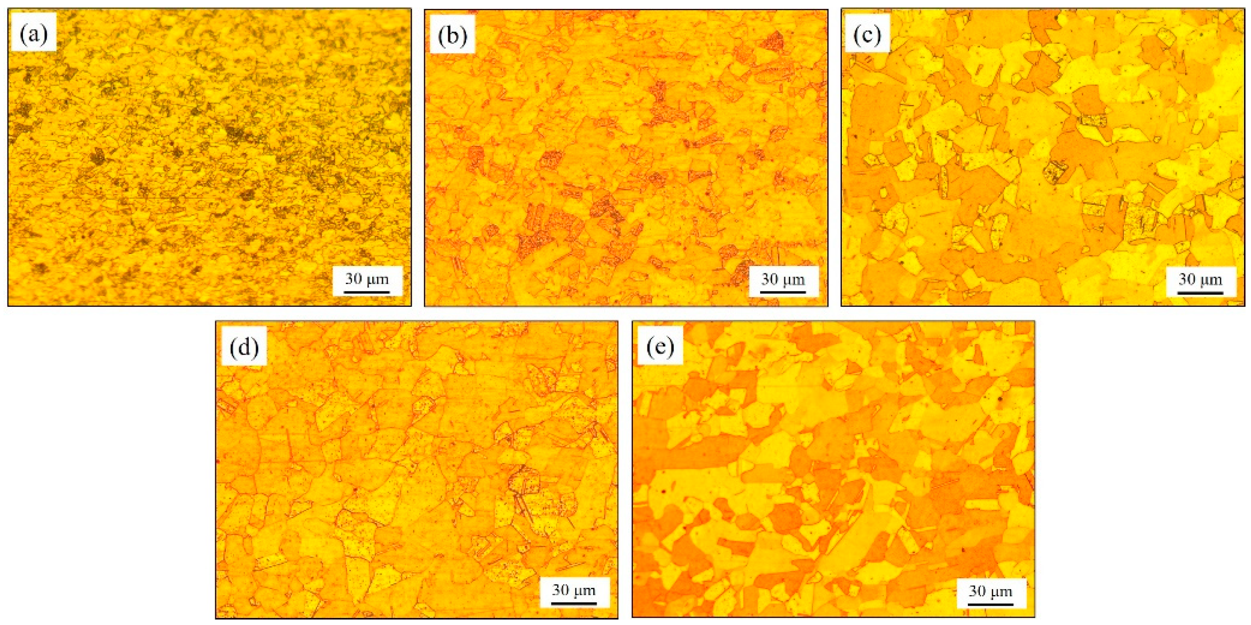
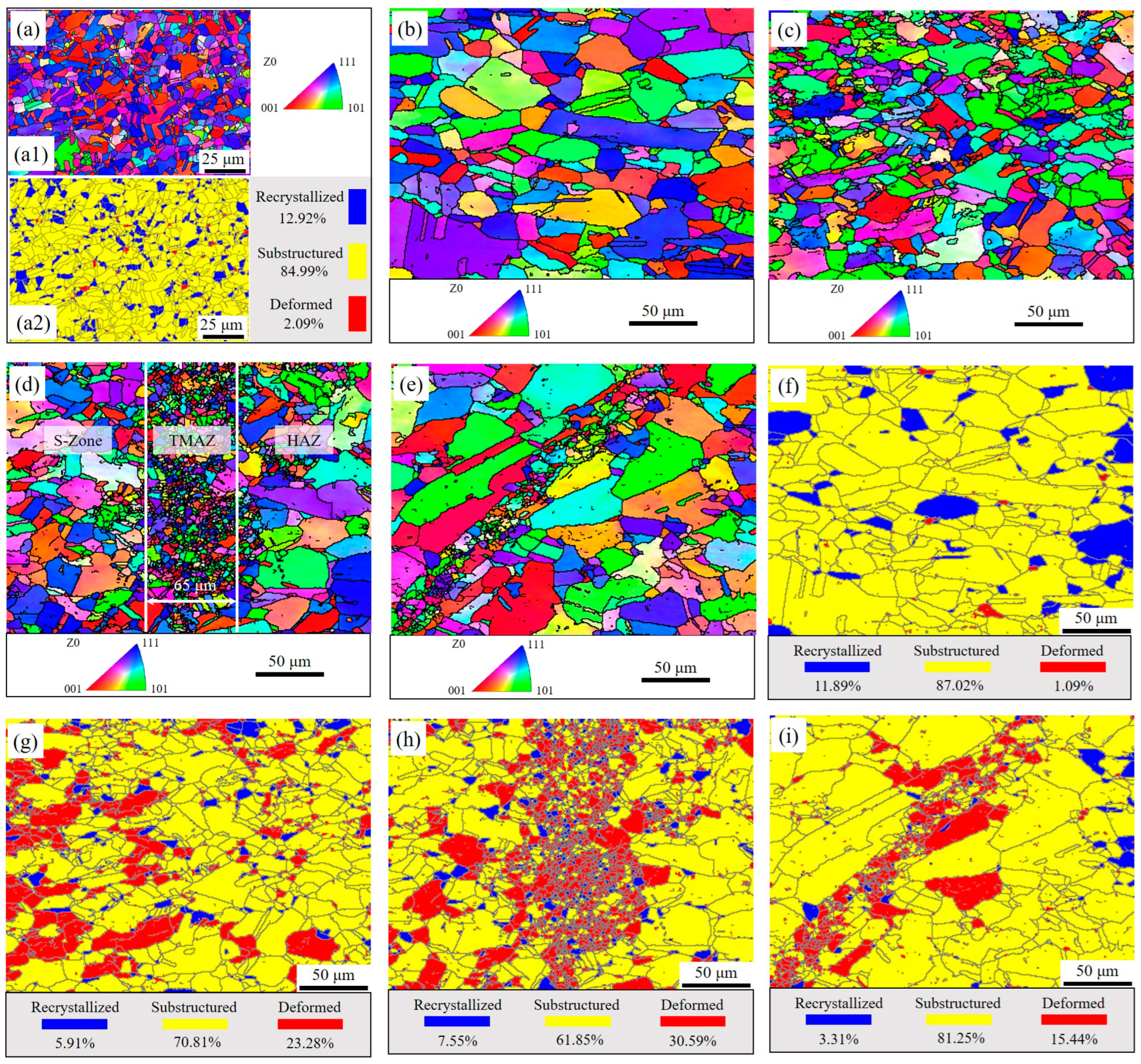
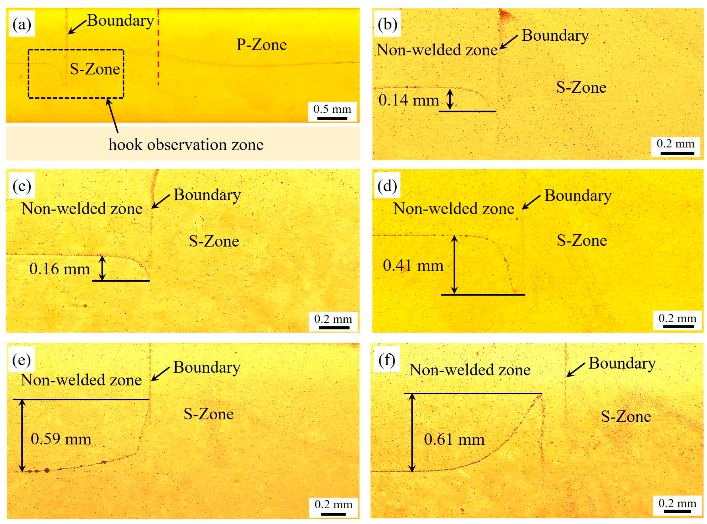
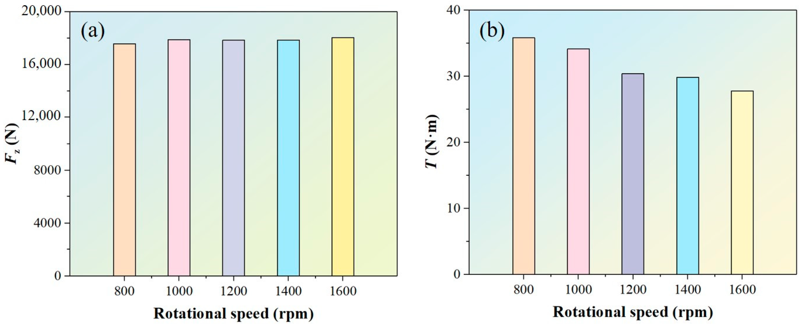
Two types of welding defects were identified: incomplete refill and surface unevenness. These defects can be mitigated by increasing the rotational speed or adjusting the relative position of the tool. The cross-sectional morphology of the welded joints at different rotational speeds exhibited similar structural features. Higher rotational speeds resulted in coarser microstructures in the stir zone. The average grain size in the S-Zone was smaller than that of the P-Zone. In the welded joints, the substructured grains are predominant. The proportion of substructured grains in the S-Zone is lower than that in the P-Zone, whereas the fraction of deformed grains in the S-Zone is higher than that in the P-Zone. With increasing rotational speed, the hook height gradually increased. During welding, the maximum axial force occurred near the second dwell stage before the welding process concluded, while the maximum torque appeared during the sleeve plunging stage.
(2)
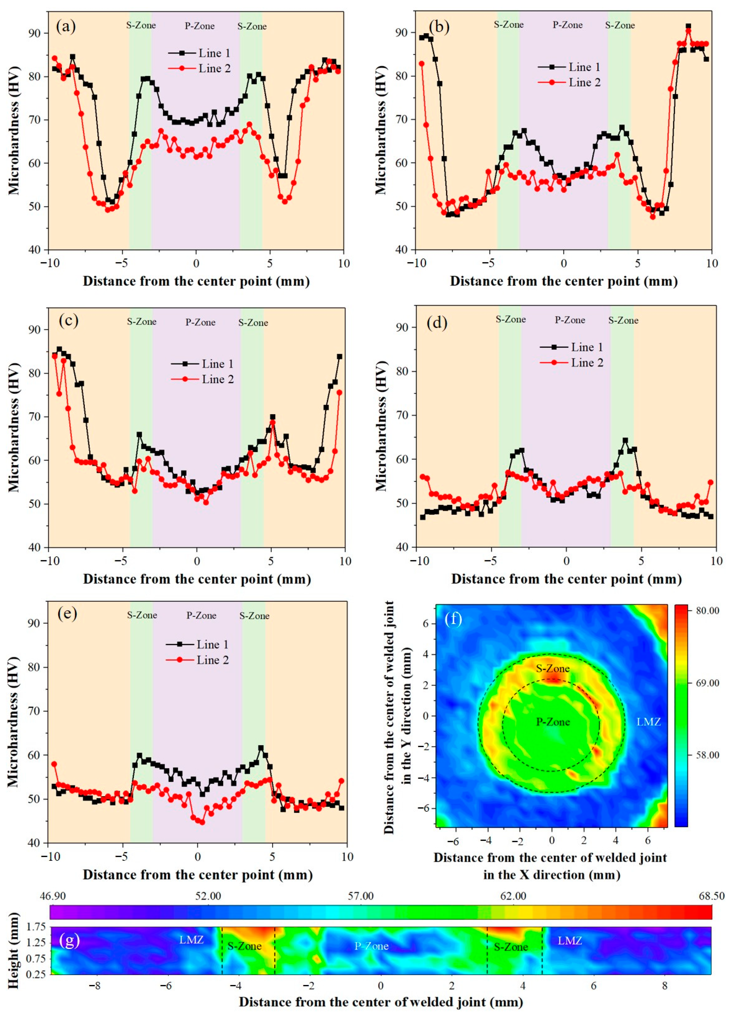
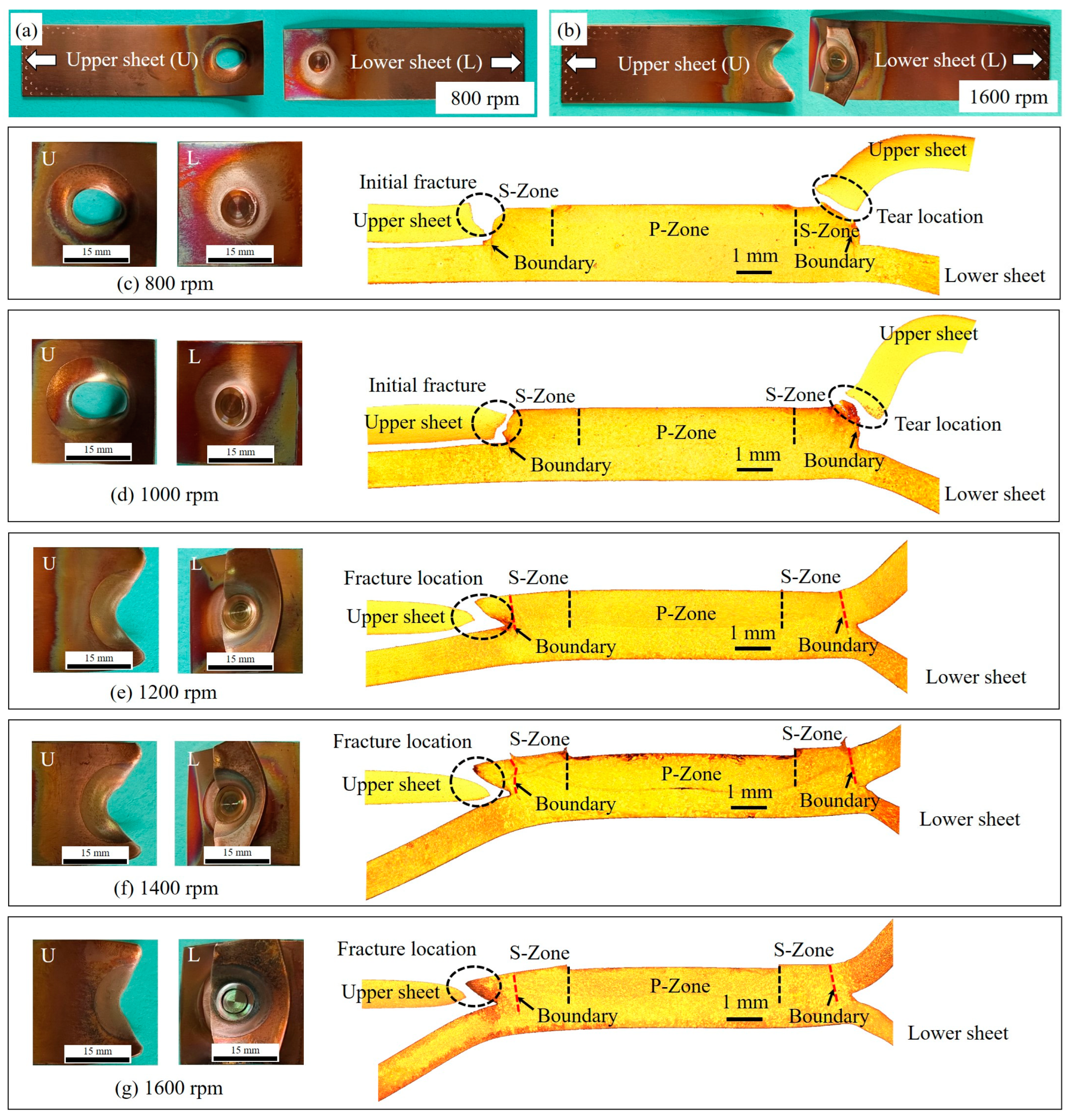
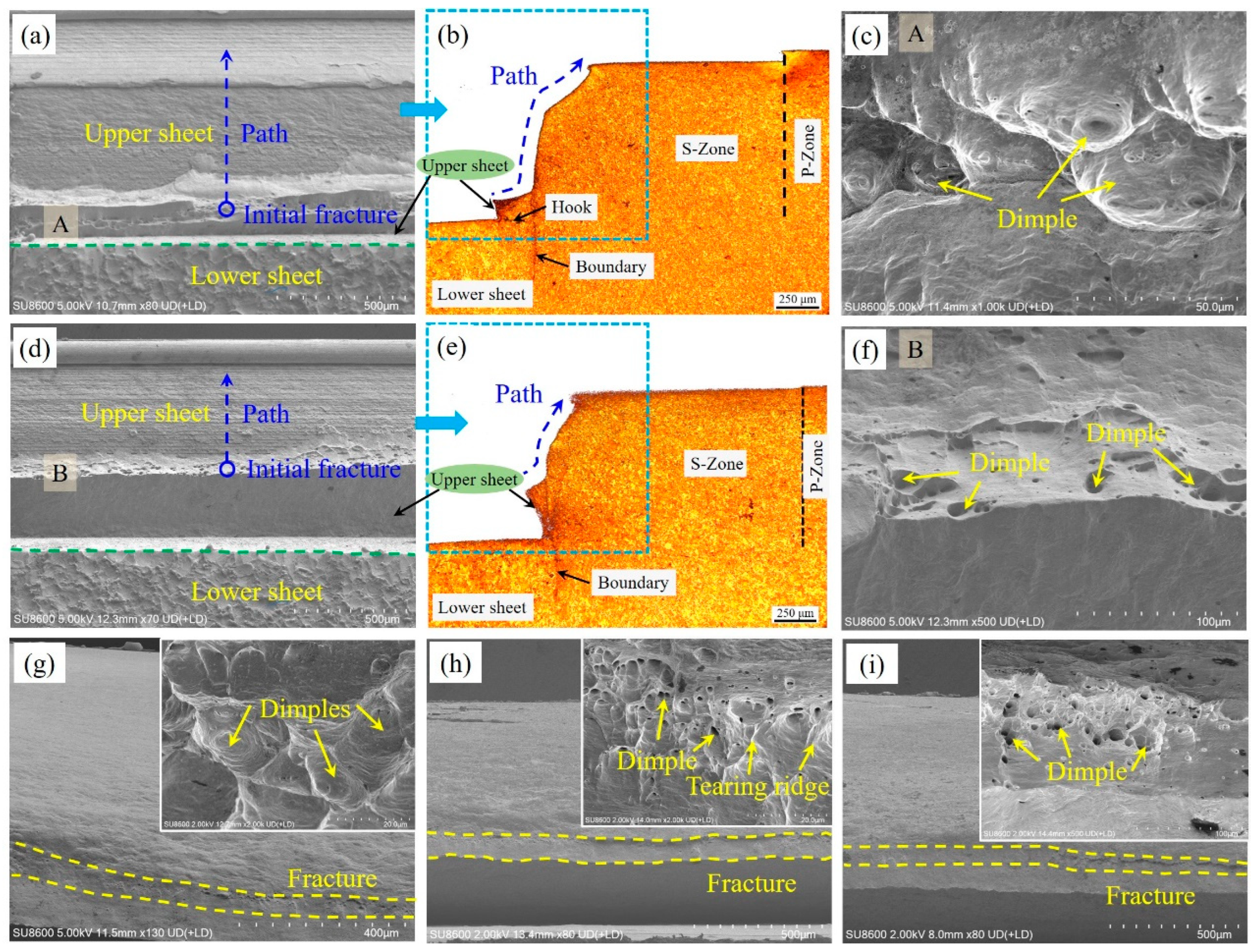
The microhardness in the welded zone exhibited an M-shaped distribution, with higher microhardness at the top of the S-Zone and the lowest microhardness at the center of the P-Zone. With increasing rotational speed, the tensile-shear failure load of the welded joint initially increased and then decreased, peaking at 5229 N at a rotational speed of 1200 rpm. At rotational speeds of 800 rpm and 1000 rpm, the welded joints exhibited plug fracture. The initial fracture originated near the bottom of the upper sheet outside the boundary of the welded joint. In the rotational speed range of 1200 rpm to 1600 rpm, the fracture type shifted to upper sheet fracture. The fracture location was at an LMZ within the upper sheet, at a certain distance outside the boundary of the welded joint, coinciding with the transition zone between residual tensile stress and compressive stress.
(3)
This study bridges the knowledge gap in understanding the influence of rotational speed on the RFSSW joint characteristics of pure copper, a high-melting-point and high-thermal-conductivity material, which has not been fully revealed in previous research. The findings contribute to a deeper understanding of the welding characteristics of high-melting-point and high-thermal-conductivity materials. Future research should focus on investigating the effects of other process parameters such as plunge depth and welding time on the welding characteristics of pure copper, as well as developing numerical simulation models and temperature field measurements for RFSSW of pure copper to gain a more comprehensive understanding of the welding process.

Author Contributions

Conceptualization, I.N.K. and X.G.; methodology, D.J.; software, X.G.; formal analysis, D.J.; investigation, H.W.; resources, H.W. and W.S.; writing—original draft preparation, X.G.; writing—review and editing, I.N.K. and H.W.; visualization, W.S.; supervision, I.N.K. All authors have read and agreed to the published version of the manuscript.

Funding

This research was funded by the National Natural Science Foundation of China, grant number 52405479; the Key Research Project of Natural Science in Anhui Higher Education Institutions, grant number 2022AH051947; the Anhui Province Excellent Young Teacher Cultivation Project, grant number YQYB2024066; the Open Research Project of Anhui Simulation Design and Modern Manufacture Engineering Technology Research Center, grant number SGCZXYB2302; and the Research Project of Huangshan University, grant number hsxyssd006.

Data Availability Statement

Data will be made available on request.

Acknowledgments

The authors would like to express their gratitude to the Anhui Simulation Design and Modern Manufacture Engineering Technology Research Center for providing the welding and testing equipment. The authors also sincerely appreciate the guidance provided by Shouzhen Cao during the EBSD testing.

Conflicts of Interest

The authors declare no conflicts of interest.

References

  1. Forsström, A.; Bossuyt, S.; Yagodzinskyy, Y.; Tsuzaki, K.; Hänninen, H. Strain localization in copper canister FSW welds for spent nuclear fuel disposal. J. Nucl. Mater. 2019, 523, 347–359. [Google Scholar] [CrossRef]
  2. Ólafsson, D.; Vilaça, P.; Vesanko, J. Multiphysical characterization of FSW of aluminum electrical busbars with copper ends. Weld. World 2020, 64, 59–71. [Google Scholar] [CrossRef]
  3. Zhang, H.; Jiao, K.X.; Zhang, J.L.; Liu, J. Experimental and numerical investigations of interface characteristics of copper/steel composite prepared by explosive welding. Mater. Des. 2018, 154, 140–152. [Google Scholar] [CrossRef]
  4. Chen, D.; Li, J.; Xiong, J.; Shi, J.; Dou, J.; Zhao, H. Enhance mechanical properties of refill friction stir spot welding joint of alclad 7050/2524 aluminum via suspension rotating process. J. Mater. Res. Technol. 2021, 12, 1243–1251. [Google Scholar] [CrossRef]
  5. Heidarzadeh, A.; Jabbari, M.; Esmaily, M. Prediction of grain size and mechanical properties in friction stir welded pure copper joints using a thermal model. Int. J. Adv. Manuf. Technol. 2015, 77, 1819–1829. [Google Scholar] [CrossRef]
  6. Barlas, Z. Effect of friction stir spot weld parameters on Cu/CuZn30 bimetal joints. Int. J. Adv. Manuf. Technol. 2015, 80, 161–170. [Google Scholar] [CrossRef]
  7. Zohoori-Shoar, V.; Eslami, A.; Karimzadeh, F.; Abbasi-Baharanchi, M. Resistance spot welding of ultrafine grained/nanostructured Al 6061 alloy produced by cryorolling process and evaluation of weldment properties. J. Manuf. Process. 2017, 26, 84–93. [Google Scholar] [CrossRef]
  8. Wang, Y.; Tao, W.; Yang, S. A method for improving joint strength of resistance spot welds of AA 5182-O aluminum alloy. J. Manuf. Process. 2019, 45, 661–669. [Google Scholar] [CrossRef]
  9. Li, G.; Zhou, L.; Zhou, W.; Song, X.; Huang, Y. Influence of dwell time on microstructure evolution and mechanical properties of dissimilar friction stir spot welded aluminum–copper metals. J. Mater. Res. Technol. 2019, 8, 2613–2624. [Google Scholar] [CrossRef]
  10. Yang, X.W.; Fu, T.; Li, W.Y. Friction stir spot welding: A review on joint macro- and microstructure, property, and process modelling. Adv. Mater. Sci. Eng. 2014, 2014, 697170. [Google Scholar] [CrossRef]
  11. Fu, B.; Shen, J.; Suhuddin, U.F.H.R.; Chen, T.; dos Santos, J.F.; Klusemann, B.; Rethmeier, M. Improved mechanical properties of cast Mg alloy welds via texture weakening by differential rotation refill friction stir spot welding. Scr. Mater. 2021, 203, 114113. [Google Scholar] [CrossRef]
  12. Suhuddin, U.F.H.R.; Mironov, S.; Sato, Y.S.; Kokawa, H.; Lee, C.W. Grain structure evolution during friction-stir welding of AZ31 magnesium alloy. Acta Mater. 2009, 57, 5406–5418. [Google Scholar] [CrossRef]
  13. Patel, V.K.; Bhole, S.D.; Chen, D.L. Influence of ultrasonic spot welding on microstructure in a magnesium alloy. Scr. Mater. 2011, 65, 911–914. [Google Scholar] [CrossRef]
  14. Zhang, Z.; Yang, X.; Zhang, J.; Zhou, G.; Xu, X.; Zou, B. Effect of welding parameters on microstructure and mechanical properties of friction stir spot welded 5052 aluminum alloy. Mater. Des. 2011, 32, 4461–4470. [Google Scholar] [CrossRef]
  15. Pankaj, P.; Medhi, T.; Dhara, L.N.; Tiwari, A.; Biswas, P. A route for properties enhancement by utilizing external auxiliary energy systems for FSW of aluminum-steel. CIRP J. Manuf. Sci. Technol. 2023, 46, 204–229. [Google Scholar] [CrossRef]
  16. Ge, X.; Jiang, D.; Song, W.; Wang, H. Effects of tool plunging path on the welded joint properties of pinless friction stir spot welding. Lubricants 2023, 11, 150. [Google Scholar] [CrossRef]
  17. Uematsu, Y.; Tokaji, K.; Tozaki, Y.; Kurita, T.; Murata, S. Effect of re-filling probe hole on tensile failure and fatigue behaviour of friction stir spot welded joints in Al–Mg–Si alloy. Int. J. Fatigue 2008, 30, 1956–1966. [Google Scholar] [CrossRef]
  18. Buffa, G.; Fratini, L.; Piacentini, M. On the influence of tool path in friction stir spot welding of aluminum alloys. J. Mater. Process. Technol. 2008, 208, 309–317. [Google Scholar] [CrossRef]
  19. Suresh, S.; Venkatesan, K.; Natarajan, E.; Rajesh, S.; Lim, W.H.J.M.E. Evaluating weld properties of conventional and swept friction stir spot welded 6061-T6 aluminium alloy. Mater. Express 2019, 9, 851–860. [Google Scholar] [CrossRef]
  20. Suresh, S.; Venkatesan, K.; Natarajan, E.; Rajesh, S. Performance analysis of nano silicon carbide reinforced swept friction stir spot weld joint in AA6061-T6 alloy. Silicon 2021, 13, 3399–3412. [Google Scholar] [CrossRef]
  21. Tozaki, Y.; Uematsu, Y.; Tokaji, K. A newly developed tool without probe for friction stir spot welding and its performance. J. Mater. Process. Technol. 2010, 210, 844–851. [Google Scholar] [CrossRef]
  22. Prangnell, P.B.; Bakavos, D. Novel approaches to friction spot welding thin aluminium automotive sheet. Mater. Sci. Forum 2010, 638–642, 1237–1242. [Google Scholar] [CrossRef]
  23. Yazdi, S.R.; Beidokhti, B.; Haddad-Sabzevar, M. Pinless tool for FSSW of AA 6061-T6 aluminum alloy. J. Mater. Process. Technol. 2019, 267, 44–51. [Google Scholar] [CrossRef]
  24. Alaeibehmand, S.; Mirsalehi, S.E.; Ranjbarnodeh, E. Pinless FSSW of DP600/Zn/AA6061 dissimilar joints. J. Mater. Res. Technol. 2021, 15, 996–1006. [Google Scholar] [CrossRef]
  25. Schilling, C.; dos, S.J. Method and Device for Joining at Least Two Adjoining Work Pieces by Friction Welding. US Patent US6722556B2, 20 April 2004. [Google Scholar]
  26. Zhao, Y.-Q.; Yang, H.-K.; Andriia, A.; Lo, H.-H.; Li, J.-X. Refill friction stir spot welding (RFSSW): A review of processing, similar/dissimilar materials joining, mechanical properties and fracture mechanism. J. Iron. Steel Res. Int. 2024, 31, 1825–1839. [Google Scholar] [CrossRef]
  27. Mehta, K.; Astarita, A.; Carlone, P.; Della Gatta, R.; Vyas, H.; Vilaça, P.; Tucci, F. Investigation of exit-hole repairing on dissimilar aluminum-copper friction stir welded joints. J. Mater. Res. Technol. 2021, 13, 2180–2193. [Google Scholar] [CrossRef]
  28. Derlatka, A.; Lacki, P. Experimental study and numerical simulation of cellular I-beam manufactured using refill friction stir spot welding technology. Thin-Walled Struct. 2024, 200, 111890. [Google Scholar] [CrossRef]
  29. Zhang, D.; Dong, J.; Xiong, J.; Jiang, N.; Li, J.; Guo, W. Microstructure characteristics and corrosion behavior of refill friction stir spot welded 7050 aluminum alloy. J. Mater. Res. Technol. 2022, 20, 1302–1314. [Google Scholar] [CrossRef]
  30. Liu, Z.; Fan, Z.; Liu, L.; Miao, S.; Lin, Z.; Wang, C.; Zhao, Y.; Xin, R.; Dong, C. Refill friction stir spot welding of AZ31 magnesium alloy sheets: Metallurgical features, microstructure, texture and mechanical properties. J. Mater. Res. Technol. 2023, 23, 3337–3350. [Google Scholar] [CrossRef]
  31. Li, Y.; Sun, G.; Zhang, Z.; Zhou, L.; Guo, N.; Meng, Q.; Dong, J.; Zhao, H. Texture evolution of refill friction stir spot welding in alclad 2A12-T42 aluminum alloy. Mater. Charact. 2023, 205, 113289. [Google Scholar] [CrossRef]
  32. Becker, N.; dos Santos, J.F.; Klusemann, B. Experimental investigation of crack propagation mechanism in refill friction stir spot joints of AA6082-T6. Eng. Fract. Mech. 2024, 300, 109963. [Google Scholar] [CrossRef]
  33. Gera, D.; Fu, B.; Suhuddin, U.F.H.R.; Plaine, A.; Alcantara, N.; dos Santos, J.F.; Klusemann, B. Microstructure, mechanical and functional properties of refill friction stir spot welds on multilayered aluminum foils for battery application. J. Mater. Res. Technol. 2021, 13, 2272–2286. [Google Scholar] [CrossRef]
  34. de Castro, C.C.; Plaine, A.H.; de Alcântara, N.G.; dos Santos, J.F. Taguchi approach for the optimization of refill friction stir spot welding parameters for AA2198-T8 aluminum alloy. Int. J. Adv. Manuf. Technol. 2018, 99, 1927–1936. [Google Scholar] [CrossRef]
  35. Li, S.; Xing, Y.; Liu, X. Effect of rotational speed on forming and tensile shear properties of 2060 Al-Li RFSSW joint. Trans. China Weld. Inst. 2019, 40, 156–160. [Google Scholar] [CrossRef]
  36. Chai, P.; Wang, Y. Effect of rotational speed on microstructure and mechanical properties of 2060 aluminum alloy RFSSW joint. Met. Mater. Int. 2019, 25, 1574–1585. [Google Scholar] [CrossRef]
  37. Dong, Z.; Hu, W.; Ai, X.; Lv, Z. Effect of rotation speed on intermetallic compounds and failure load of RFSSW-ed dissimilar Al/Mg. Trans. Indian Inst. Met. 2019, 72, 2249–2256. [Google Scholar] [CrossRef]
  38. Li, G.; Zhou, L.; Luo, L.; Wu, X.; Guo, N. Microstructural evolution and mechanical properties of refill friction stir spot welded alclad 2A12-T4 aluminum alloy. J. Mater. Res. Technol. 2019, 8, 4115–4129. [Google Scholar] [CrossRef]
  39. Shi, Y.; Yue, Y.; Zhang, L.; Ji, S.; Wang, Y. Refill friction stir spot welding of 2198-T8 aluminum alloy. Trans. Indian Inst. Met. 2018, 71, 139–145. [Google Scholar] [CrossRef]
  40. Zou, Y.; Li, W.; Chu, Q.; Shen, Z.; Wang, F.; Tang, H.; Vairis, A.; Liu, L. The impact of macro/microstructure features on the mechanical properties of refill friction stir spot–welded joints of AA2219 alloy with a large thickness ratio. Int. J. Adv. Manuf. Technol. 2021, 112, 3093–3103. [Google Scholar] [CrossRef]
  41. Zhou, L.; Luo, L.Y.; Zhang, T.P.; He, W.X.; Huang, Y.X.; Feng, J.C. Effect of rotation speed on microstructure and mechanical properties of refill friction stir spot welded 6061-T6 aluminum alloy. Int. J. Adv. Manuf. Technol. 2017, 92, 3425–3433. [Google Scholar] [CrossRef]
  42. Li, Z.; Gao, S.; Ji, S.; Yue, Y.; Chai, P. Effect of rotational speed on microstructure and mechanical properties of refill friction stir spot welded 2024 Al alloy. J. Mater. Eng. Perform. 2016, 25, 1673–1682. [Google Scholar] [CrossRef]
  43. Nan, X.; Zhao, H.; Jia, B.-B.; Ma, C.; Sun, G.; Zhou, L.; Wang, R.; Song, X. The effect of rotational speed on microstructure and mechanical properties of Al/Ti dissimilar joint produced by refill friction stir spot welding. J. Mater. Eng. Perform. 2024, 34, 1812–1824. [Google Scholar] [CrossRef]
  44. Cui, Y.; Wang, B.; Dong, W.; Li, Z.; Yan, J. Refill friction stir spot welding of an Al-Li alloy: The effects of rotating speed and welding time on joint microstructure and mechanical properties. Metals 2024, 14, 1383. [Google Scholar] [CrossRef]
  45. Kluz, R.; Kubit, A.; Trzepiecinski, T.; Faes, K.; Bochnowski, W. A weighting grade-based optimization method for determining refill friction stir spot welding process parameters. J. Mater. Eng. Perform. 2019, 28, 6471–6482. [Google Scholar] [CrossRef]
  46. Xiong, J.; Peng, X.; Shi, J.; Wang, Y.; Sun, J.; Liu, X.; Li, J. Numerical simulation of thermal cycle and void closing during friction stir spot welding of AA-2524 at different rotational speeds. Mater. Charact. 2021, 174, 110984. [Google Scholar] [CrossRef]
  47. Ji, S.; Li, Z.; Wang, Y.; Ma, L.; Zhang, L. Material flow behavior of refill friction stir spot welded LY12 aluminum alloy. High Temp. Mater. Process. 2017, 36, 495–504. [Google Scholar] [CrossRef]
  48. GB/T 3355-2014; Test Method for in-Plane Shear Response of Polymer Matrix Composite Materials. Chinese National Standard, General Administration of Quality Supervision, Inspection and Quarantine of the People’s Republic of China, Standardization Administration of China: Beijing, China, 2014.
  49. Łogin, W.; Śliwa, R.E.; Ziaja, W.; Ostrowski, R. The influence of modification of the geometry of the front surface of the RFSSW tool inner sleeve on the fatigue life of joints during joining clad sheets made of aluminum alloy 2024-T3. Arch. Civ. Mech. Eng. 2024, 25, 17. [Google Scholar] [CrossRef]
  50. Wu, T.; Liu, Y.; Ji, S.; Sui, X.; Li, Z. Refill friction stir spot welding of a graphene-reinforced AA 6061 aluminum alloy. JOM 2025, 77, 1280–1291. [Google Scholar] [CrossRef]
  51. Li, Z.; Ji, S.; Ma, Y.; Chai, P.; Yue, Y.; Gao, S. Fracture mechanism of refill friction stir spot-welded 2024-T4 aluminum alloy. Int. J. Adv. Manuf. Technol. 2016, 86, 1925–1932. [Google Scholar] [CrossRef]
  52. Zuo, Y.; Kong, L.; Liu, Z.; Lv, Z.; Wen, H. Process parameters optimization of refill friction stir spot welded Al/Cu joint by response surface method. Trans. Indian Inst. Met. 2020, 73, 2975–2984. [Google Scholar] [CrossRef]
  53. de Castro, C.C.; Plaine, A.H.; Dias, G.P.; de Alcântara, N.G.; dos Santos, J.F. Investigation of geometrical features on mechanical properties of AA2198 refill friction stir spot welds. J. Manuf. Process. 2018, 36, 330–339. [Google Scholar] [CrossRef]
  54. Zhao, Y.; Liu, H.; Yang, T.; Lin, Z.; Hu, Y. Study of temperature and material flow during friction spot welding of 7B04-T74 aluminum alloy. Int. J. Adv. Manuf. Technol. 2016, 83, 1467–1475. [Google Scholar] [CrossRef]
  55. Janga, V.S.R.; Awang, M.; Yamin, M.F.; Suhuddin, U.F.H.; Klusemann, B.; Santos, J.F.d. Experimental and numerical analysis of refill friction stir spot welding of thin AA7075-T6 sheets. Materials 2021, 14, 7485. [Google Scholar] [CrossRef]
  56. Marek, M.; Krzysztof Jan, K. Generalised stacking fault energies of copper alloys—Density functional theory calculations. J. Min. Metall. Sect. B 2019, 55, 271–282. [Google Scholar] [CrossRef]
  57. Cao, J.Y.; Wang, M.; Kong, L.; Guo, L.J. Hook formation and mechanical properties of friction spot welding in alloy 6061-T6. J. Mater. Process. Technol. 2016, 230, 254–262. [Google Scholar] [CrossRef]
  58. Zou, Y.; Li, W.; Yang, X.; Su, Y.; Chu, Q.; Shen, Z. Microstructure and mechanical properties of refill friction stir spot welded joints: Effects of tool size and welding parameters. J. Mater. Res. Technol. 2022, 21, 5066–5080. [Google Scholar] [CrossRef]
  59. Adamus, J.; Adamus, K. The analysis of reasons for defects formation in aluminum joints created using RFSSW technology. Manuf. Lett. 2019, 21, 35–40. [Google Scholar] [CrossRef]
  60. Kubit, A.; Faes, K.; Aghajani Derazkola, H. Refill friction stir spot welding tool plunge depth effects on shear, peel, and fatigue properties of alclad coated AA7075 aluminum joints. Int. J. Fatigue 2024, 185, 108308. [Google Scholar] [CrossRef]
  61. Fritsche, S.; Schindler, F.; de Carvalho, W.S.; Amancio-Filho, S.T. Wear mechanisms and failure analysis of a tool used in refill friction stir spot welding of AA6061-T6. Wear 2025, 560–561, 205610. [Google Scholar] [CrossRef]
  62. Silva, B.H.; Zepon, G.; Bolfarini, C.; dos Santos, J.F. Refill friction stir spot welding of AA6082-T6 alloy: Hook defect formation and its influence on the mechanical properties and fracture behavior. Mat. Sci. Eng. A 2020, 773, 138724. [Google Scholar] [CrossRef]
  63. Ragab, A.E.; Alsaty, A.; Alsamhan, A.; Al-Tamimi, A.A.; Dabwan, A.; Sayed, A.; Alghilan, W. Open-source real-time monitoring system of temperature and force during friction stir spot welding. J. Eng. Res. 2023, 2023, 1–13. [Google Scholar] [CrossRef]
  64. Badwelan, A.; Al-Samhan, A.M.; Anwar, S.; Hidri, L. Novel technique for enhancing the strength of friction stir spot welds through dynamic welding parameters. Metals 2021, 11, 280. [Google Scholar] [CrossRef]
  65. Liu, W.H.; Wu, Y.; He, J.Y.; Nieh, T.G.; Lu, Z.P. Grain growth and the Hall–petch relationship in a high-entropy fecrnicomn alloy. Scr. Mater. 2013, 68, 526–529. [Google Scholar] [CrossRef]
  66. Sun, Q.; Di, H.S.; Li, J.C.; Wu, B.Q.; Misra, R.D.K. A comparative study of the microstructure and properties of 800Mpa microalloyed C-Mn steel welded joints by laser and gas metal arc welding. Mat. Sci. Eng. A 2016, 669, 150–158. [Google Scholar] [CrossRef]
  67. Choi, I.-C.; Kim, Y.-J.; Wang, Y.M.; Ramamurty, U.; Jang, J.-i. Nanoindentation behavior of nanotwinned Cu: Influence of indenter angle on hardness, strain rate sensitivity and activation volume. Acta Mater. 2013, 61, 7313–7323. [Google Scholar] [CrossRef]
  68. Zhou, G.; Huang, T.; Su, L.; Huang, Q.; Wu, S.; Zhang, B. The microstructure and mechanical properties of deposited alcusc alloy wall structures fabricated by waam with FSP assistance. Thin-Walled Struct. 2025, 209, 112954. [Google Scholar] [CrossRef]
  69. Tang, H.W.; Li, W.Y.; Feng, X.S.; Cui, F.; Zou, Y.F. Microstructure and mechanical properties of refill friction stir spot welded Al–Mg-Li alloy joints. Weld. World 2023, 67, 385–393. [Google Scholar] [CrossRef]
  70. Rosendo, T.; Tier, M.; Mazzaferro, J.; Mazzaferro, C.; Strohaecker, T.R.; Dos Santos, J.F. Mechanical performance of AA6181 refill friction spot welds under lap shear tensile loading. Fatigue Fract. Eng. Mater. Struct. 2015, 38, 1443–1455. [Google Scholar] [CrossRef]
  71. Plaine, A.H.; Suhuddin, U.F.H.; Alcântara, N.G.; dos Santos, J.F. Microstructure and mechanical behavior of friction spot welded AA6181-T4/Ti6Al4V dissimilar joints. Int. J. Adv. Manuf. Technol. 2017, 92, 3703–3714. [Google Scholar] [CrossRef]
Figure 1. Schematic diagram of welding equipment, tools and copper sheet lap: (a) Welding machine; (b,c) RFSSW tools; (d) Lap dimensions; (e) Welding principle.
Crystals 15 00268 g001
Figure 2. Appearance and typical defects of welded joints at different rotational speeds: (a) Welded specimens at different rotational speeds; (b) Enlarged views of welded joints; (c) Incomplete refill defect at 800 rpm; (d) Surface unevenness defect at 1400 rpm.
Crystals 15 00268 g002
Figure 3. Cross-sectional macrostructure of the welded joints at different rotational speeds: (a) 800 rpm; (b) 1000 rpm; (c) 1200 rpm; (d) 1400 rpm; (e) 1600 rpm.
Crystals 15 00268 g003
Figure 4. Microstructure at zone ① under different rotational speeds: (a) 800 rpm; (b) 1000 rpm; (c) 1200 rpm; (d) 1400 rpm; (e) 1600 rpm.
Crystals 15 00268 g004
Figure 5. EBSD maps and DRX maps of the base material and different zones of ①, ②, ③ and ④: (a1) IPF map of the base material; (a2) DRX map of the base material; (b) IPF map of the Zone ①; (c) IPF map of the Zone ②; (d) IPF map of the Zone ③; (e) IPF map of the Zone ④; (f) DRX map of the Zone ①; (g) DRX map of the Zone ②; (h) DRX map of the Zone ③; (i) DRX map of the Zone ④.
Crystals 15 00268 g005
Figure 6. Hook morphology at different rotation speeds: (a) Hook observation position; (b) 800 rpm; (c) 1000 rpm; (d) 1200 rpm; (e) 1400 rpm; (f) 1600 rpm.
Crystals 15 00268 g006
Figure 7. Variations in axial force and torque at different rotational speeds: (a) 800 rpm; (b) 1000 rpm; (c) 1200 rpm; (d) 1400 rpm; (e) 1600 rpm.
Crystals 15 00268 g007
Figure 8. Peak axial forces and torques at different rotational speeds: (a) Axial force; (b) Torque.
Crystals 15 00268 g008
Figure 9. Microhardness at different rotation speeds: (a) 800 rpm; (b) 1000 rpm; (c) 1200 rpm; (d) 1400 rpm; (e) 1600 rpm; (f) Surface microhardness and (g) Cross-sectional microhardness cloud maps at 1400 rpm.
Crystals 15 00268 g009
Figure 10. Displacement-load curves and tensile-shear failure loads of the welded joints at different rotational speeds: (a) Displacement-load curves; (b) Tensile-shear failure loads.
Crystals 15 00268 g010
Figure 11. Fracture types of welded joints at different rotational speeds: (a) Fracture specimen at 800 rpm; (b) Fracture specimen at 1600 rpm; (cg) Fracture types and cross-sectional fracture locations of welded joints at different rotational speeds.
Crystals 15 00268 g011
Figure 12. Fracture morphologies of welded joints at different rotation speeds: (ac) Fracture morphologies at 800 rpm; (a) SEM image of fracture; (b) Cross-sectional image at fracture; (c) Initial fracture morphology at position A; (df) Fracture morphologies at 1000 rpm; (d) SEM image of fracture; (e) Cross-sectional image at fracture; (f) Initial fracture morphology at position B; (g) Fracture morphology at 1200 rpm; (h) Fracture morphology at 1400 rpm; (i) Fracture morphology at 1600 rpm.
Crystals 15 00268 g012
Figure 13. Residual stress on the surface of typical welded joints.
Crystals 15 00268 g013
Disclaimer/Publisher’s Note: The statements, opinions and data contained in all publications are solely those of the individual author(s) and contributor(s) and not of MDPI and/or the editor(s). MDPI and/or the editor(s) disclaim responsibility for any injury to people or property resulting from any ideas, methods, instructions or products referred to in the content.

