Article

Effect of Interface Relief on the Occurrence of Cracks at the Contact Point of Laser-Direct-Energy-Deposited Copper Alloy and Nickel Base Superalloy

1
Department of the Engine Production Technology, Samara University, Moskovskoye Shosse, 34, Samara 443086, Russia
2
Department of the Metal Technology and Aviation Material Science, Samara University, Moskovskoye Shosse, 34, Samara 443086, Russia
3
World-Class Research Center “Advanced Digital Technologies”, State Marine Technical University, Saint Petersburg 190121, Russia
*
Authors to whom correspondence should be addressed.
Crystals 2025, 15(2), 121; https://doi.org/10.3390/cryst15020121
Submission received: 11 December 2024 / Revised: 15 January 2025 / Accepted: 18 January 2025 / Published: 23 January 2025
(This article belongs to the Section Inorganic Crystalline Materials)

Abstract

:
The relevance of the study is related to the need to join dissimilar copper and nickel alloys by laser direct energy and material deposition (LDED). The purpose of research is studying the distribution of elements, structure, and properties of contact zone of nickel-based super alloy and CuCr1 bronze obtained by direct energy and material deposition with preliminary formation of relief of contact surface. For the purposes of research, samples were made from UNS C18200 copper alloy CuCr1 without relief, with a relief of 0.5 mm depth, and with a relief of 1 mm depth. The Ni50Cr33W4.5Mo2.8TiAlNb (EP648) alloy powder was deposited onto the bronze samples with a micro-relief. The deposition was produced by direct injection of energy and material. The influence of interphase interaction of CuCr-chromium carbide system on the possibility of initiation of a crack in the area of carbide secretions is not significant and does not exceed 3.1% according to CIC criterion from the background level for CuCr1 (CIC = 1.54% for CuCr1-Al4C3 interface and CIC = 3.1% for CuCr1-Cr23C6 interface). An X-ray analysis revealed the presence of tensile residual macro-stresses, arising from differences in thermal expansion coefficients in the CuCr1-EP648 interface area, which may be the main cause of crack formation. Cracks are generated and run along the grain boundaries, on which traces of excretion are visible. The contact surface in the CuCr1-EP648 interface area has no visible defects, which indicates the good adhesion of materials when applying an initial layer of EP648 by LDED. The presence of a 0.5-mm micro-relief on CuCr1 has a positive effect on the strength of the connection, as it increases the surface area of the contact CuCr1-EP648 and therefore reduces the contact stress of the breakout.

1. Introduction

Bimetal designs are widely used in various industries, including aerospace, automotive, and biomedical [1,2]. In the aerospace industry, they are particularly valuable for thermal barrier protection [3] and high heat conductivity in gas turbines and rocket engines [4]. Additive manufacturing (AM) has further expanded the capabilities of these bimetallic components, allowing for complex internal configurations and multi-material systems that are required in modern engineering. In particular, the combustion chambers for liquid propellant rocket engines have become the main candidates for use as AM [5,6] due to their complex design, often requiring internal lining cooling channels, made of high-tensile copper alloys, in combination with an outer structural shell made of a high-tensile nickel alloy [7].
The use of additive technologies in modern technology allows complex shape designs to be obtained from heterogeneous materials.
For the creation of large-scale products and assemblies, direct energy and material deposition technology is mainly used. This allows the labor intensity of manufacturing products to be reduced by several times. However, when mixed alloys are joined together, there is no fusion, and cracks do not allow the required quality to be achieved.
One of the possible options for solving the problem of joining heterogeneous materials—bronze- and nickel-based super alloys—can be to create a certain regular surface roughness. The material adhesion can be improved due to the uneven and heterogeneous thermal profile in the melting and crystallization zone between the materials.
In general, the researchers paid much attention to the effect of the boundary of metal layers, joined by metallurgical way, on nano- and micro-scales [8,9,10]. The impact of macro-relief on the boundary properties of bound materials has been the subject of relatively few studies [11]. The effect of macroscopic flat, wave, and sloping phase boundaries on shock wave propagation in AM GRCop-84-Inconel® 625 bi-metallic alloys was investigated by experiments with single-axis plate deformation under gas gun impact [12].
Laser direct energy deposition (LDED) technology, applied to join dissimilar materials, has its own features, which require the consideration of differences in the thermophysical properties of the materials to be joined and the consideration of differences in the depth of penetration of the laser beam for these materials, which is particularly important when forming their interface area [11].
The proposed study is aimed at studying the structure and properties of the contact zone of nickel base high-tensile alloy and CuCr1 bronze, obtained by the LDED method and material with pre-formed macro-roughness of the contact surface.

2. Materials and Methods

2.1. Raw Materials

The following materials were used for experiments:
-
Pressed rod made from CuCr1 (UNS C18200 copper alloy) according to Russian Standard [13] with a diameter of 40 mm;
-
Nickel alloy powder Ni50Cr33W4.5Mo2.8TiAlNb (EP648) with a fraction size of 60–110 μm.

2.2. Experimental Setup

Experimental design of the research:
-
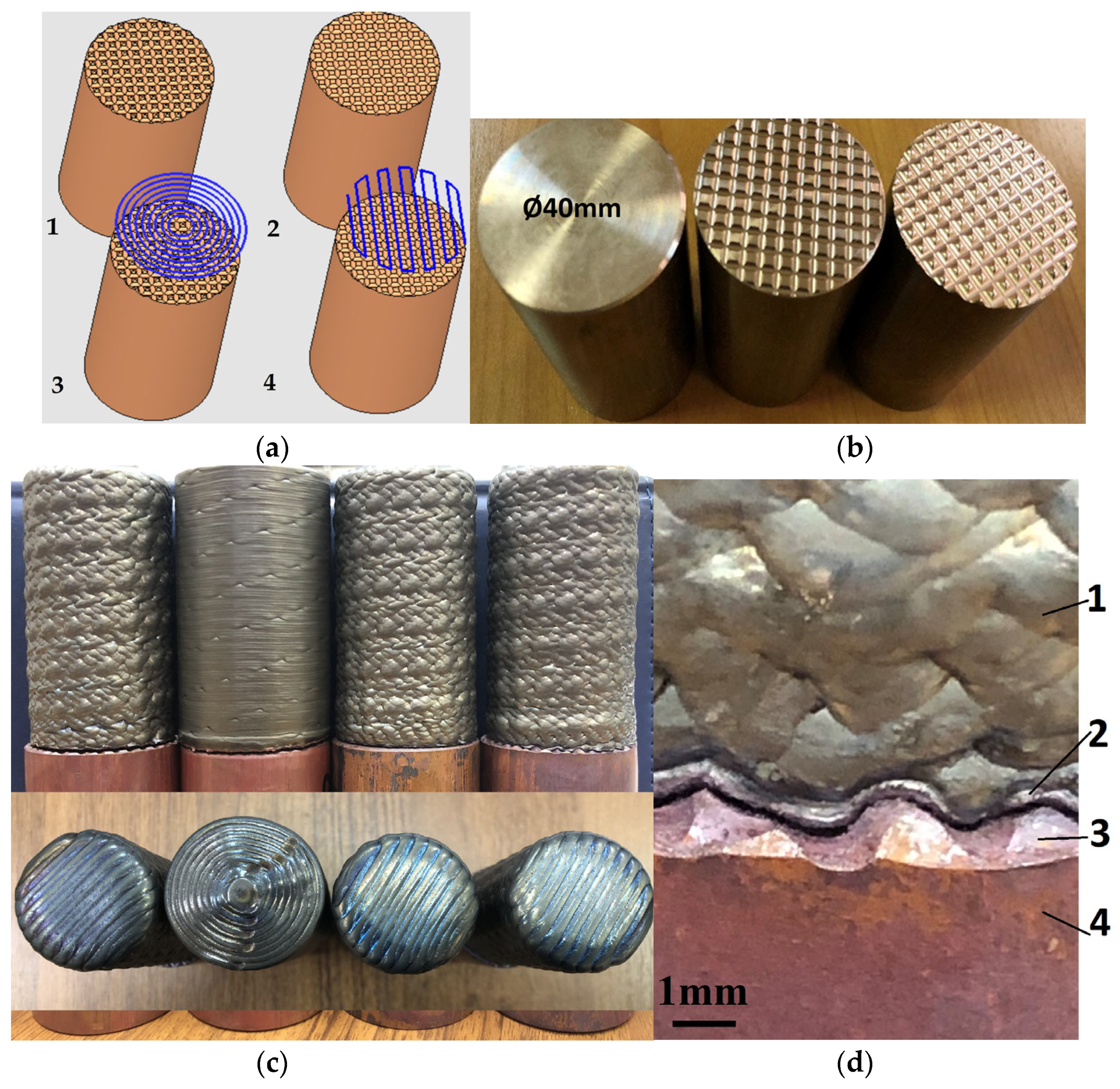
Preparation of samples from copper alloy CuCr1 with different cases of regular surface roughness;
-
Production of bimetallic samples by LDED superalloy technology using 2 different deposition tool path strategies;
-
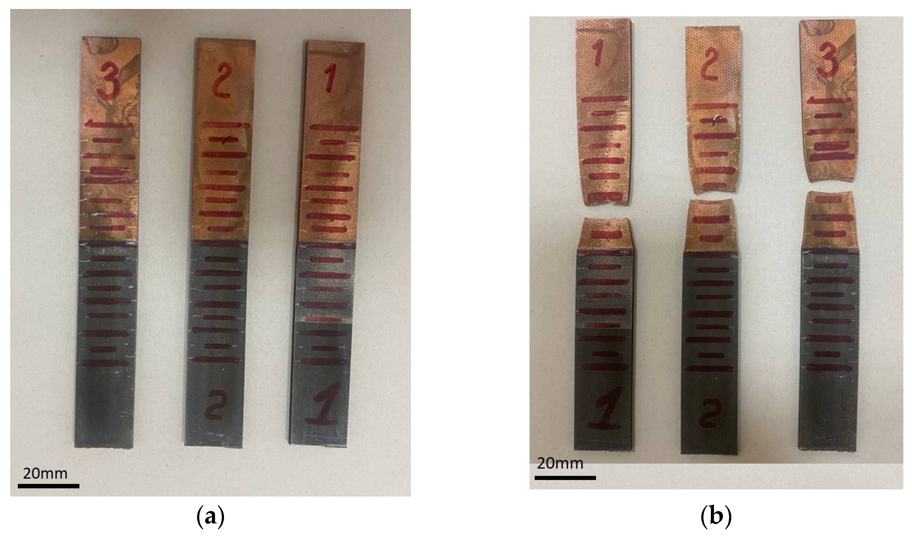
Cutting of standard samples and conducting tensile tests;
-
Investigation of the area of interface of bimetal connection and identification of causes of possible crack formation.
For the purposes of research, samples with a diameter of 40 mm and a height of 70 mm were made of copper alloy CuCr1 with different surface relief: 1 sample with a flat end, 2 samples with a 0.5-mm depth of textured macro-roughness, and 2 samples with a 1-mm depth of textured macro-roughness. The minimization of the random error in the experiment, and the creation of the macro-roughness at specified depths, were performed by using 3D milling with a high precision of 0.05 mm. The clad volume of the samples has been built up with LDED using the metal powder of the EP648 alloy.
The deposition was carried out by the direct feeding of energy and material according to the modes of LDED shown in Table 1. All experiments were carried out using ILIST (ILIST, St-Petersburg, Russia; Nd:YAG, 4000 W, cw laser) with a laser beam movement system, powder feeding system, coaxial nozzle based on the Fanuc 6–axis robot, and a 2–axis rotary platform.
The following tool path strategies were used for deposition:
-
Zig-Zag (raster).
-
Concentric circles.
Kinds of tool path strategies were chosen due to often-faced ones on production technologies and cut device options.
Total height of the clad volume—70 mm, total height of the received sample—140 mm.
The macro-structure cross-section of the sample is shown in Figure 1 as a macro-structure. The sample was removed from the material bond area of the bimetallic sample.
Figure 2 shows the process of deposition of EP648 powder onto a substrate made of bronze CuCr1 with the ILIST equipment. The processing parameters were chosen based on preliminary experiments and the possibilities given by the equipment.
Figure 3 shows samples with prepared textured macro-roughness of different depths subjected to LDED (a, b), samples with different deposition tool path strategies (c), macro-image of the interface area from the outside (d).

2.3. Tension Tests

The samples of standard sizes 130 × 20 × 3 (type 2, No 23 ISO 6892-1:2019 [14]) for tensile tests were obtained by cutting plates from cylindrical samples Ø40 × 70 mm (Figure 3) with a fine 0.5-mm macro-roughness, grown in optimal conditions (Table 1). The before and after strain test samples are shown in Figure 4.
A tensile test was conducted on a SHIMADZU EHF-E servo hydraulic testing machine (SHIMADZU Corporation, Kyoto, Japan).
No cracks were found at the interface in tensile tests. The samples have been broken to form a typical neck on the CuCr1 bronze. The strength achieved is 241 ± 0.6 MPa, which corresponds to the characteristics of the material CuCr1 copper alloy at the annealed state.

2.4. Microstructure Characterisation

The selection of the samples for structural analysis was carried out by cutting the obtained samples in a longitudinal direction using an electro-erosional wire-cutting machine. Then, one of the fragments from each sample was placed in a cylindrical shape and was coated with epoxy resin to make a metallographic investigation.
Macro-structural studies of the samples in the crack development zone were carried out using the stereoscopic microscope Altami SPM0880 (Altami Ltd., St-Petersburg, Russia.). Microstructure investigations were conducted using a TESCAN VEGA3 SBH scanning electron microscope (Tascan, Brno—Kohoutovice, Czech Republic), equipped with the power analysis apparatus «Oxford Instruments X-Act».
The microstructure was studied after etching with 5 mL of solution H2SO4, 3 mL of HNO3, and 92 mL of HCl. The phase composition of the obtained structures was determined by X-ray diffraction (PSA) on a diffractometer “DRON-7” (“Burevesnik”, St-Petersburg, Russia) (manufacturer, city, and country) with Cu-Ka radiation.

3. Results

The preliminary analysis showed that the samples cladded by the tool path strategy ‘concentric circles’ are most prone to crack formation (Figure 5). In all cases of this strategy, the cracks develop from the periphery towards the center. This is because the heating during the LDED process is uniform along the annular regions. In the peripheral annular region, due to the difference in the thermal expansion coefficients of the CuCr1-EP648 layers, higher values of radial stresses are obtained because the heat dissipation rate is lower than the thermal absorption rate. Therefore, the normal stresses responsible for cracking will be greater. In this regard, it was decided to analyze the interface of CuCr1-EP648 only for samples cladded by the raster strategy, which showed the absence of cracks during cladding at optimum modes according to Table 1. Thus, the samples obtained by the raster tool path strategy of cladding with three variants of a textured macro-roughness depth of initial substrate were subjected to the interface quality study.
Figure 6 shows a photograph of the specimen fractured along the crack showing traces of 1 mm macro-roughness. The contours of the protrusions are clearly visible in the outline.
On samples with a macro-roughness depth of 0.5 mm and samples with a smooth surface, cracks were detected only at increasing laser power above 2000 W in comparison to optimal technological modes shown in Table 1. On the contrary, a decrease in power leads to the formation of the luck of fusion of the heat-resistant alloy material. Since the difference in the contact area of CuCr1-EP648 layers for samples with fine macro-roughness in comparison to the contact area of samples with large macro-roughness is insignificant and amounts to about 7%, it can be concluded that the main cause of crack formation for large macro-roughness is its depth—1 mm. In this case, in the process of cladding layers of EP648 during the movement of the melt bath, strong vortex flows are formed, leading to the appearance of gas pores and increased liquation.
The map of chemical element distribution in the area of material contact and crack appearance (Figure 7) shows that the increased concentration of elements Al, C, O is observed on the surface of the pore with subsequent formation and development of the crack. Evaporation and oxidation of Al in the EP648 alloy is thought to be the cause of pore formation. As the EP648 deposit layer forms on the CuCr1 surface, Al penetrates into the CuCr1. Excessive overestimation of the macro-roughness depth when cladding the first layer is the cause of intense vortex formation in the melt bath and, as a consequence, the release of aluminum carbide on the pore surface.
The XRD diagrams of near and outside the crack CuCr1 regions were obtained from the study of the interface of CuCr1-EP648 samples (Figure 8 and Figure 9).

4. Discussion

The authors’ study [14] describes the conditions of Al4C3 and mixture carbide formation at high temperatures in solid-phase carbonate recovery processes at reduced CO partial pressure. The XRD database was used to determine the Al4C3 content when reducing corundum to aluminum carbide in inert gas environments at 1500–1700 °C.
Comparing the resulting XRD diagrams (Figure 7 and Figure 8) with data of research [15] you can find aluminum carbide peaks at the indexed intervals of 2θ. It can be seen that the XRD peaks corresponding to the Al4C3 phase are within the values of angles 2θ = 30… 33°, and corundum and carbon within the values of 2θ = 25… 28°.
The carbon thermic recovery of solid oxides is known to occur through the gas phase when the oxides are recovered by CO gas, which is regenerated by a Boudouard reaction. The recovery of corundum by CO with the formation of aluminium carbide can occur through the following reaction:
2Al2O3 + 12CO = Al4C3 + 9CO
In addition to the described reaction, the following cyclic sequence of reactions is possible, leading to the formation of aluminium carbide under certain conditions of partial gas pressures in the pores [15]:
(3)→(4)↔(5)→(6),
where numbers in brackets denote equations of reactions (3)–(6)
Al2O3 + 2C = Al2O(g) + 2CO;
Al2O3 + 4Al(g) = 3Al2O(g)
Al2O(g) + C = 2Al(g) + CO
2Al2O(g) + 5C = Al4C3 + 2CO
As noted above, cracks in CuCr1 can be formed by overlaps of thermal stresses in the material mass and interphase interface caused by the release of carbides along grain boundaries.
In addition to the aluminum carbide in the area of the interphase interface, there is a possibility of chromium carbide, which can be added to CuCr1 due to the vortex effect in the bath melt when cladding the EP648.
To quantify the influence of the interphase interaction of the system’s ‘main material—precipitation’ on the stressed state, one can refer to the continuity preservation condition (CPC) and the crack initiation criteria CIC [16,17].
The first parameter, dependent on the microelement composition, describes the dimensionless relation of thermodynamic values at a local point. The second parameter defines the amount of CPC exceeded at the crack border compared to its safe value outside the crack. The CPC at the boundary of two phases v and w is described by a dependency
C P C v / w = 1 4 C Ω v + C Ω w C p v C Ω v α m v + C p w C Ω w α m w 1 T 0 1 T m v
C Ω v ,   C Ω w —the molar heat capacities of matrix (v) and precipitation (w) phase;
C p v ,   C p w —isobar molar heat capacities of matrix (v) and precipitation (w) phase;
T 0 —normal temperature, T m v —matrix melting point;
α m v ,   α m w —the linear expansion coefficients of the matrix phase and the precipitation phase.
For the matrix phase, CPC is determined by the
C P C v = 1 4 C Ω v C p v C Ω v α m v 1 T 0 1 T m v
To determine the excess of internal stress in the interphase space compared with the matrix, enter the CIC parameter
C I C = C P C v / w C P C v C P C v
The relationship of the isochoric heat capacity with the isochoric heat capacity is determined by the Magnus–Lindemann equation [18]
C p = C Ω + β T 3 / 2 , β = 6.076 n T m * 3 / 2 ,
where n is the number of atoms in a compound (n = l + m + k); T m * —melting point of the compound with chemical formula AlBmDk.
Taking into account the Magnus–Lindeman equation, the CPC dependency is:
C P C v / w = 1 24.304 C Ω v + C Ω w n w α m w T m w 3 / 2 + n v α m v T m v 3 / 2 1 T 0 1 T m v
C P C v = 1 24.304 C Ω v n v α m v T m v T m v T 0 1 / 2 1
Table 2 shows the results of the estimation of the effect of the interphase interaction of the CuCr1-carbide system on stress and crack formation.
It should be noted that cracks are generated and go along the grain boundaries (fragile destruction)—Figure 10. The specific material structure in the form of columnar grains, which is prone to liquation cracking, forms with DED. The columnar structures were a result of the rapid cooling and solidification rate of the AM process and formed with the growth direction along the direction of laser scanning [24]. Modern copper alloys GRCop-84 and GRCop-42, developed for NASA, contain Cr and Nb [4,5,6]. Cr and Nb have limited solubility in Cu, which causes the formation of Cr2Nb precipitates inside a relatively pure Cu matrix upon solidification [25,26]. The Cr2Nb precipitates can contribute to strengthening within GRCop alloys [27,28] and, due to their high thermal stability, can restrict Cu grain growth at high temperatures through grain boundary pinning [25,27]. Grain boundary pinning provides a physical barrier that interferes with the directional growth of grains, promoting a more uniform and equiaxed microstructure instead of allowing the formation of columnar grains.
The conditions of crack formation were considered from the point of view of thermodynamics of interphase interaction and the ratio of the influence of macro- and micro-residual stresses on crack formation, taking into account the initial microgeometry of the surface in the contact area.
It should be noted that cracking due to thermal phase transition occurs not only in metal alloys [29] but also in organic crystals [30].
The topology of the crystalline phase has a great influence on the level of interfacial interaction, which can be the cause of crack formation. The main factors determining the topological properties of crystalline phases are temperature and pressure [31], their conductivity depending on chemical composition [31], and atomistic electrostatic potentials for inorganics or molecular electrostatic potentials for organic compounds [32,33,34,35].
Surface geometry is used to tune and control the surface interactions of materials, thereby modifying their interface properties. The study shows that the crystalline phase influences the formation of cracks at the contact points of alloys. The properties are determined by boundary-localized states where unusual interaction phenomena occur and are observed. Consequently, the creation of tunable surface structures involves phenomena at the atomic and molecular levels. Facets, edges, and defects in the crystalline phase, as well as deviations in interparticle distances, are essential. The crystal structural architecture of both bulk and surface materials with tunable properties changes the relations between the chemical composition of crystals, the symmetry of crystal structures, and their topological properties.

5. Conclusions

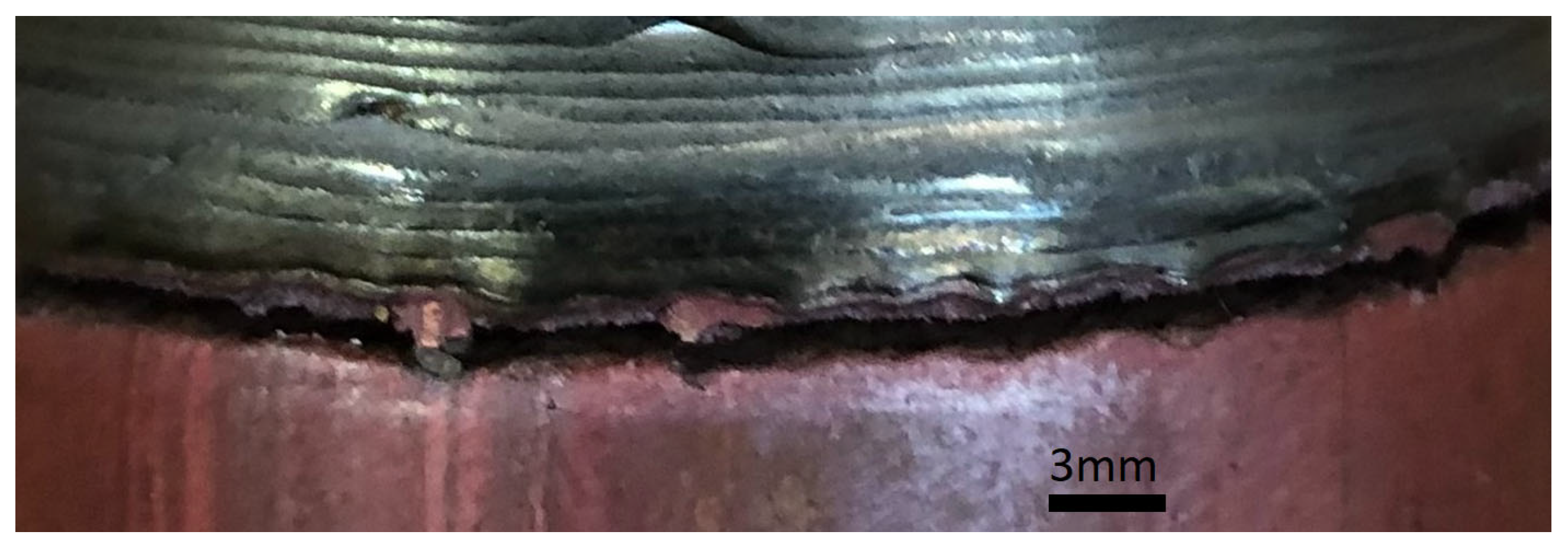
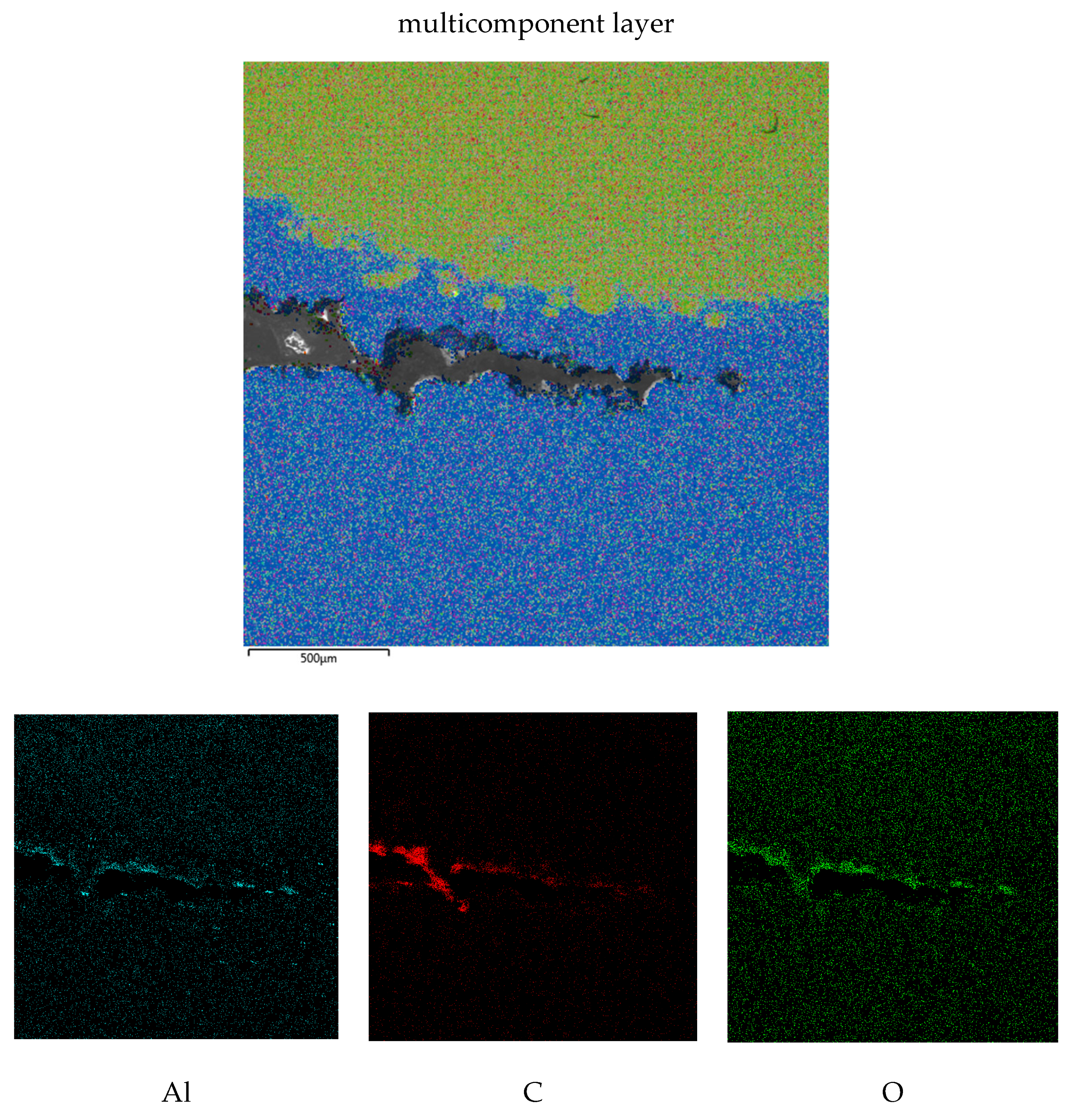
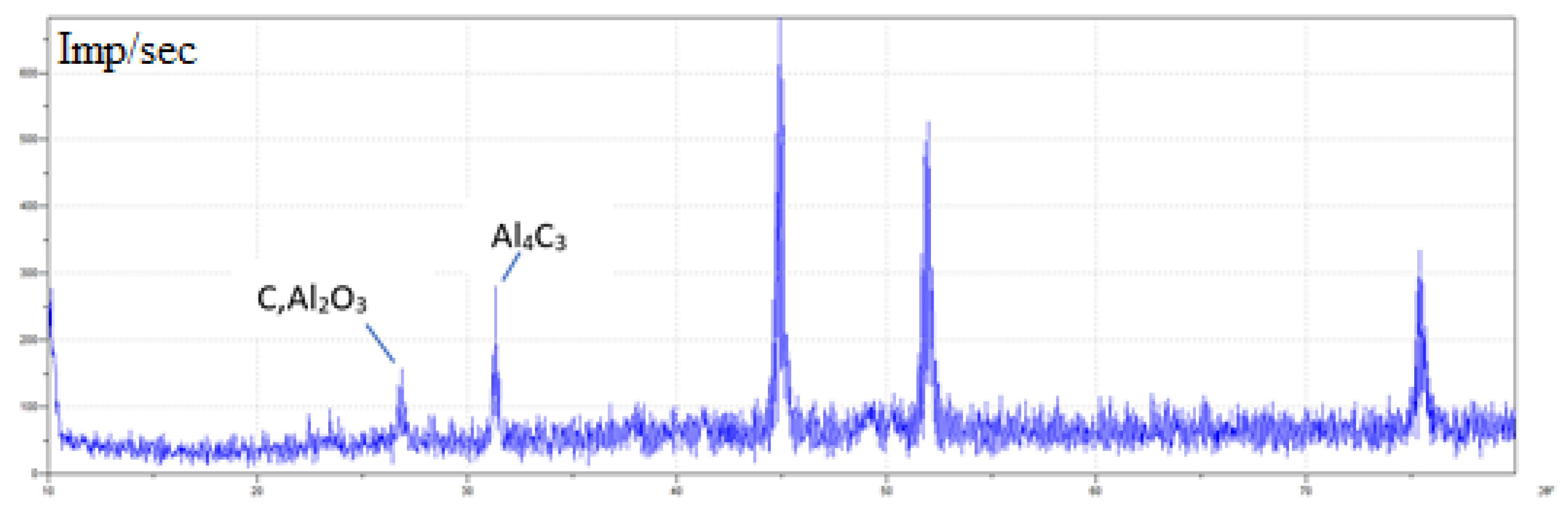
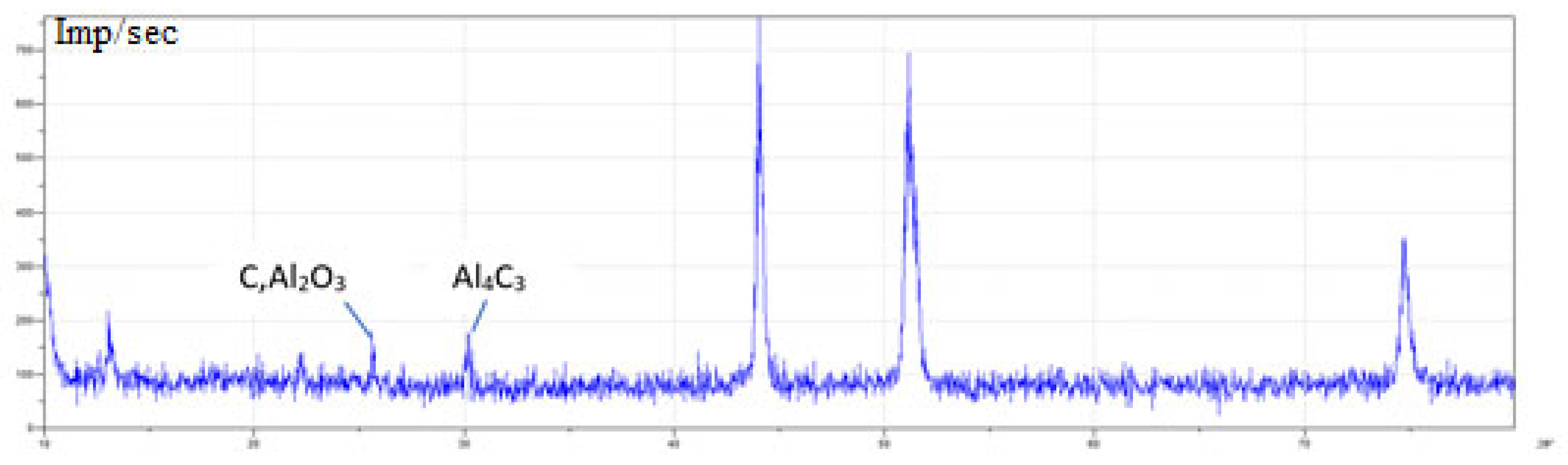
  • The calculations in Table 1 show that the influence of the interfacial interaction of the CuCr1-carbide system on the possibility of crack initiation in the area of carbide precipitations is not significant and does not exceed 3.1% by the CIC criterion from the background values for CuCr (CIC = 1.54% for the CuCr1-Al4C3 interface and CIC = 3.1% for the CuCr1-Cr23C6 interface). Consequently, the main cause of crack initiation is macroscale residual stresses due to the difference in thermal expansion coefficients in the CuCr1-EP648 interface region. Nevertheless, cracks nucleate and follow the grain boundaries (brittle fracture), on which traces of precipitates are visible.
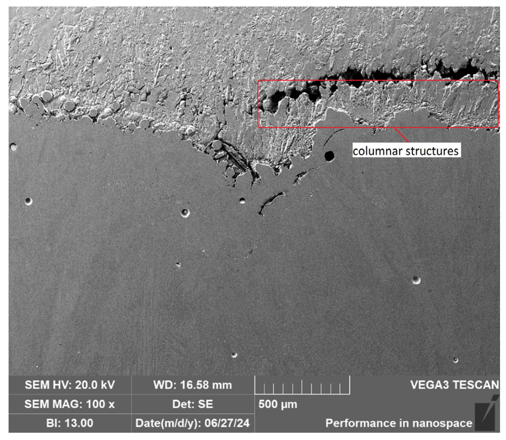
  • The contact surface in the area of the CuCr1-EP648 interface has no visible defects, which demonstrates good adhesion of the materials during the deposition of the EP648 layer by DED.
  • The presence of medium-sized macro-roughness of 0.5 mm on the CuCr1 surface before the DED of the Ni-based alloy has a positive effect on the strength of the joint, as it increases the contact surface area of CuCr1-EP648 and, therefore, reduces the contact fracture stresses.
  • The study examines crack formation through the lens of thermodynamics, focusing on how macro- and micro-residual stresses, along with the initial surface microgeometry, influence this process at contact points in joining alloys. Surface geometry plays a crucial role in modifying material interactions and properties. The crystalline phase has a significant impact on crack formation, with boundary-localized states generating unique interaction phenomena.

Author Contributions

Conceptualization, A.K. (Alexander Khaimovich) and V.S.; methodology, A.K. (Alexander Khaimovich), A.B. and E.N.; sample’s characterization, M.K. and E.Z.; validation, M.K., A.B. and E.N.; investigation, A.K. (Alexander Khaimovich), A.B. and E.N.; data curation, M.K. and A.K. (Anton Kovchik); writing—original draft preparation, E.N., A.K. (Anton Kovchik) and M.K.; writing—review and editing, E.N., M.K. and A.K. (Alexander Khaimovich); visualization, M.K., A.K. (Anton Kovchik) and E.N.; project administration, V.S., A.K. (Alexander Khaimovich) and E.N.; funding acquisition, V.S., A.K. (Alexander Khaimovich) and E.Z. All authors have read and agreed to the published version of the manuscript.

Funding

This work was financially supported by the Ministry of Science and Higher Education of the Russian Federation within the framework of the «World-class Science Center» program: Advanced Digital Technologies (Grant Agreement No. 075-15-2022-312, 20 April 2022).

Data Availability Statement

The original contributions presented in the study are included in the article, further inquiries can be directed to the corresponding authors.

Conflicts of Interest

The authors declare no conflicts of interest.

References

  1. DebRoy, T.; Wei, H.L.; Zuback, J.S.; Mukherjee, T.; Elmer, J.W.; Milewski, J.O.; Beese, A.M.; Wilson-Heid, A.; De, A.; Zhang, W. Additive manufacturing of metallic components–Process, structure and properties. Prog. Mater. Sci. 2018, 92, 112–224. [Google Scholar] [CrossRef]
  2. Milewski, J.O. Understanding metal for additive manufacturing. In Additive Manufacturing of Metals: From Fundamental Technology to Rocket Nozzles, Medical Implants, and Custom Jewelry; Springer Series in Materials, Science; Milewski, J.O., Ed.; Springer International Publishing: Cham, Switzerland, 2017; pp. 49–83. [Google Scholar] [CrossRef]
  3. Padture, N.P.; Gell, M.; Jordan, E.H. Thermal barrier coatings for gas turbine engine applications. Science 2002, 296, 280–284. [Google Scholar] [CrossRef]
  4. Onuike, B.; Heer, B.; Bandyopadhyay, A. Additive manufacturing of Inconel 718—Copper alloy bimetallic structure using laser engineered net shaping (LENS™). Addit. Manuf. 2018, 21, 133–140. [Google Scholar] [CrossRef]
  5. Gradl, P.R.; Protz, C.S.; Ellis, D.L.; Greene, S.E. Progress in Additively Manufactured Copper-Alloy GRCop-84, GRCop-42, and Bimetallic Combustion Chambers for Liquid Rocket Engines. In Proceedings of the International Astronautical Congress (IAC), Washington, DC, USA, 21–25 October 2019; pp. 1–14. [Google Scholar]
  6. Gradl, P.R.; Protz, C.S.; Cooper, K.; Ellis, D.; Evans, L.J.; Garcia, C. GRCop-42 development and hot-fire testing using additive manufacturing powder bed fusion for channel–cooled combustion chambers. In Proceedings of the AIAA Propulsion Energy Forum, Indianapolis, IN, USA, 19–22 August 2019; pp. 1–26. [Google Scholar]
  7. Gradl, P.R.; Protz, C.S.; Zagorski, K.; Doshi, V.; McCallum, H. Additive manufacturing and hot-fire testing of bimetallic GRCop-84 and C-18150 channel-cooled combustion chambers using powder bed fusion and inconel 625 hybrid directed energy deposition. In Proceedings of the AIAA Propulsion Energy Forum, Indianapolis, IN, USA, 19–22 August 2019; pp. 1–13. [Google Scholar] [CrossRef]
  8. Yang, Y.; Wang, C.; Chen, X.; Hu, H.; Chen, K.; Fu, Y. Effects of the phase interface on spallation damage nucleation and evolution in multiphase alloy. Alloys Compd. 2018, 740, 321–329. [Google Scholar] [CrossRef]
  9. Srinivasan, S.G.; Baskes, M.I.; Wagner, G.J. Spallation of single crystal nickel by void nucleation at shock induced grain junctions. J. Mater. Sci. 2006, 41, 7838–7842. [Google Scholar] [CrossRef]
  10. Specht, P.E.; Thadhani, N.N.; Weihs, T.P. Configuration effects on shock wave propagation in Ni-Al multilayer composites. J. Appl. Phys. 2012, 111, 073527. [Google Scholar] [CrossRef]
  11. Iams, A.D.; Lienert, T.J.; Otazu, D.A.; Ramoni, M. Effects of deposition sequence on microstructural evolution in additively manufactured Cu-Cr-Nb alloy/superalloy bimetallic structures. Addit. Manuf. Lett. 2023, 6, 100151. [Google Scholar] [CrossRef]
  12. Boddorff, A.K.; Jang, S.; Kennedy, G.; Taminger, K.; Thadhani, N.N. Spall failure of additively manufactured two-layered Cu–Ni bimetallic alloys. J. Appl. Phys. 2022, 131, 175901. [Google Scholar] [CrossRef]
  13. Russian Standard GOST 18175-78; Tinless Bronzes, Pressure-Treated Stamps. State Committee of the USSR on Product Quality Management and Standards: Moscow, USSR, 1978; 13p.
  14. International Standard ISO 6892-1:2019; The Materials Are Metal. The Tensile Test. Part 1. Test Method at Room Temperature. International Organization for Standardization (ISO): Geneva, Switzerland, 2019; 9p.
  15. Li, J.; Zhang, G.; Liu, D.; Ostrovski, O. Low-temperature Synthesis of Aluminium Carbide. ISIJ Int. 2011, 51, 870–877. [Google Scholar] [CrossRef]
  16. Khaimovich, A.; Shishkovsky, I.; Erisov, Y.; Agapovichev, A.; Smelov, V.; Razzhivin, V. Research on Cracked Conditions in Nickel Chrome Alloy Ni50Cr33W4.5Mo2.8TiAlNb, Obtained by Direct Laser Deposition. Metals 2022, 12, 1902. [Google Scholar] [CrossRef]
  17. Shishkovsky, I.; Kakovkina, N.; Nosova, E.; Khaimovich, A. Laser In Situ Synthesis of Gradient Fe-Ti Composite during Direct Energy Deposition Process. J. Manuf. Mater. Process 2023, 7, 66. [Google Scholar] [CrossRef]
  18. Moracheskij, A.; Sladkov, I. Thermodynamic Calculations in Metallurgy; Metallurgiya: Moscow, Russia, 1985; 136p. (In Russian) [Google Scholar]
  19. Deffrennes, G.; Gardiola, B.; Allam, M.; Chaussende, D.; Pisch, A.; Andrieux, J.; Schmid-Fetzer, R.; Dezellus, O. Critical assessment and thermodynamic modeling of the Al–C system. Calphad 2019, 66, 101648. [Google Scholar] [CrossRef]
  20. Pisch, A.; Pasturel, A.; Deffrennes, G.; Dezellus, O.; Benigni, P.; Mikaelian, G. Investigation of the thermodynamic properties of Al4C3: A combined DFT and DSC study. Comput. Mater. Sci. 2020, 171, 109100. [Google Scholar] [CrossRef]
  21. Japan Atomic Energy Agency. Thermodynamic Database for Nuclear Fuels and Reactor Materials. Available online: https://thermodb.jaea.go.jp/data/en/td/Cr23C6.html (accessed on 9 January 2025).
  22. Pripisnov, O. Synthesis of Composite Materials Based on Chrome Carbides with the Application of Preliminary Mechanical Activation. Ph.D. Thesis, MISIS, Moscow, Russia, 10 March 2015; p. 97. (In Russian). [Google Scholar]
  23. Available online: https://www.matweb.com/search/DataSheet.aspx?MatGUID=3f65d35b2aa74047a29a2f85172ce2a6 (accessed on 9 January 2025).
  24. Chen, Y.; Zhang, K.; Huang, J.; Hosseini, S.R.E.; Li, Z. Characterization of heat affected zone liquation cracking in laser additive manufacturing of Inconel 718. Mater. Des. 2016, 90, 586–594. [Google Scholar] [CrossRef]
  25. Minneci, R.P.; Lass, E.A.; Bunn, J.R.; Choo, H.; Rawn, C.J. Copper-based alloys for structural high-heat-flux applications: A review of development, properties, and performance of Cu-rich Cu–Cr–Nb alloys. Int. Mater. Rev. 2021, 66, 394–425. [Google Scholar] [CrossRef]
  26. Yang, Z.Q.; Chisholm, M.F.; Yang, B.; Ma, X.L.; Wang, Y.J.; Zhuo, M.J.; Pennycook, S.J. Role of crystal defects on brittleness of C15 Cr 2Nb Laves phase. Acta Mater. 2012, 60, 2637–2646. [Google Scholar] [CrossRef]
  27. Ellis, D.L.; Michal, G.M. Precipitation Strengthened High Strength, High Conductivity Cu-Cr-Nb Alloys Produced by Chill Block Melt Spinning. 1989. Available online: https://ntrs.nasa.gov/search.jsp?R=19900002537 (accessed on 9 January 2025).
  28. Kini, A.R.; Maischner, D.; Weisheit, A.; Ponge, D.; Gault, B.; Jägle, E.A.; Raabe, D. In-Situ synthesis via laser metal deposition of a lean Cu–3.4Cr–0.6Nb (at%) conductive alloy hardened by Cr nano-scale precipitates and by Laves phase micro-particles. Acta Mater. 2020, 197, 330–340. [Google Scholar] [CrossRef]
  29. Zhai, Z.; Pan, W.; Liang, B.; Liu, Y.; Zhang, Y. Behavior, Microstructure and properties of selective laser melted Al-Mn-Mg-Sc-Zr Alloy. Crystals 2022, 12, 565. [Google Scholar] [CrossRef]
  30. Pathan, J.R.; Balan, H.; Commins, P.; Ravi, A.; Al-Handawi, M.B.; Hou, I.C.-Y.; Naumov, P.; Sureshan, K.M. A self-healing crystal that repairs multiple cracks. J. Am. Chem. Soc. 2024, 146, 27100–27108. [Google Scholar] [CrossRef]
  31. Bose, A.; Banerjee, R.; Narayan, A. Pressure-induced magnetic and topological transitions in non-centrosymmetric MnIn2Te4. J. Phys. Condens. Matter. 2024, 36, 505807. [Google Scholar] [CrossRef]
  32. Joshi, B.; Thamizhavel, A.; Ramakrishnan, S. Superconductivity in cubic noncentrosymmetric PdBiSe crystal. J. Phys. Conf. Ser. 2015, 592, 012069. [Google Scholar] [CrossRef]
  33. Bolat, R.; Guevara, J.M.; Leinen, P.; Knol, M.; Arefi, H.H.; Maiworm, M.; Findeisen, R.; Temirov, R.; Hofmann, O.T.; Maurer, R.J.; et al. Electrostatic potentials of atomic nanostructures at metal surfaces quantified by scanning quantum dot microscopy. Nat. Commun. 2024, 15, 2259. [Google Scholar] [CrossRef] [PubMed]
  34. Matten, M.; Lange, T.; Rohe, M.; Mei, B.; Reichenberger, S.; Barcikowski, S. Defect-selective energy barrier crossing during adsorption of colloidal gold nanoparticles on zinc sulfide crystals under overall electrostatic repulsion. J. Phys. Chem. C 2024, 128, 18622–18633. [Google Scholar] [CrossRef]
  35. Wang, Y.; Xing, J.; Zhao, Y.; Wang, Y.; Zhao, J.; Jiang, X. Alloying driven antiferromagnetic skyrmions on NiPS3 monolayer: A first-principles calculation. Adv. Sci. 2024, 11, 2401048. [Google Scholar] [CrossRef]
Figure 1. Cross-section of sample for CuCr1-EP648 bonding modes.
Crystals 15 00121 g001
Figure 2. Process of EP648 Ni-based super alloy deposition onto a copper alloy substrate: 1 nozzle, 2 EP648 deposited volume, 3 copper alloy substrates with textured macro-roughness, 4 grown samples.
Crystals 15 00121 g002
Figure 3. Samples subjected to the LDED. (a)—preparation of the textured macro-roughness for creating a bimetallic interface (1—0.5 mm depth of the macro-roughness, 2—1 mm depth of the macro-roughness, 3 and 4—deposition tool path with «concentric circles» and «zig-zag» strategies); (b)—prepared macro-roughness of samples; (c)—grown samples (side and top view); (d)—side view of bimetallic interface (1—EP648 DED build volume, 2—EP648 buffer deposited layers, 3—macro-roughness of copper alloy surface, 4—copper alloy rod.
Crystals 15 00121 g003
Figure 4. Samples for tensile tests (a)—before testing, (b)—after testing.
Crystals 15 00121 g004
Figure 5. Peripheral crack formation during cladding using the ‘concentric circles’ strategy.
Crystals 15 00121 g005
Figure 6. The fracture surface of the sample whose surface was macro-roughened to 1-mm depth before LDED.
Crystals 15 00121 g006
Figure 7. Distribution of chemical elements in sample 1 material in the crack development zone.
Crystals 15 00121 g007
Figure 8. XRD-diagram of the interface of the samples EP648- CuCr1 in the area CuCr1 on the crack.
Crystals 15 00121 g008
Figure 9. XRD-diagram of the interface of samples EP648-CuCr1 in the area CuCr1 on the section without crack.
Crystals 15 00121 g009
Figure 10. Formation of cracks in CuCr1 along the edges of the column structures.
Crystals 15 00121 g010
Table 1. Modes of laser direct energy deposition used in research.
Technological Parameters
Laser Power, W1800
Scan Speed, mm/s25
Laser Spot Size, mm2.7
Width of the roller, mm2.5
Hatch Spacing, mm1.67
Layer Thickness, mm0.6
Pre-heating of the substrate (CuCr1 samples with a diameter of 40 mm and a height of 70 mm) to T = 650 °C. Heating time—7 min, heating power—3000 W, rotation angle of the unit on the boards—30 degrees. The deposition tool path strategy is raster. Buffering layers were built using a 15-degree angle of inclination. The first 3 layers—without pauses at 50% speed, then 2 layers at 75% speed with pauses and nozzle tilt off.
Depth of textured macro-roughness, mm 0.5
Technological pause between layers, s40
Table 2. Evaluation of the effects of interphase interaction of CuCr1-carbide system on the stressed state.
Al4C3Cr23C6Copper Alloy (CuCr1)-Matrix
[19,20][21,22][23]
Isochoric heat capacity Cv, J·mol−1·K−1
120696.3624.61
Melting temperature Tm, K
247017901346
Coefficient of thermal expansion, K−1
1.00 × 10−51.10 × 10−51.700 × 10⁻⁵
Continuity preservation condition CPC (Equation (11))CPC (Equation (12))
2.65 × 10−22.53 × 10−22.61 × 10⁻²
Crack initiation criteria CIC (Equation (9))
1.54 × 10−23.07 × 10−20
Disclaimer/Publisher’s Note: The statements, opinions and data contained in all publications are solely those of the individual author(s) and contributor(s) and not of MDPI and/or the editor(s). MDPI and/or the editor(s) disclaim responsibility for any injury to people or property resulting from any ideas, methods, instructions or products referred to in the content.

