Article

A Long-Wave Infrared Circularly Polarized Photodetector Based on an Array of Trapezoidal Silicon Pillars

1
Postdoctoral Innovation Practice Base, Chengdu Polytechnic, 83 Tianyi Street, Chengdu 610041, China
2
Sichuan Provincial Engineering Research Center of Thermoelectric Materials and Devices, Chengdu 610041, China
3
Kunming Institute of Physics, Kunming 650223, China
4
Institute of Intelligent Photonics, Nankai University, Tianjin 300071, China
5
Institute of Semiconductors, Chinese Academy of Sciences, Beijing 100083, China
*
Authors to whom correspondence should be addressed.
Crystals 2025, 15(11), 993; https://doi.org/10.3390/cryst15110993 (registering DOI)
Submission received: 9 October 2025 / Revised: 9 November 2025 / Accepted: 12 November 2025 / Published: 17 November 2025
(This article belongs to the Special Issue Metamaterials and Their Devices, Second Edition)

Abstract

Integrating metasurface-based polarizing filters atop photodetectors enables the expansion of detection capabilities from intensity to polarization, offering significant potential for applications requiring high-precision discrimination in scientific, industrial, and defense sectors. However, such metasurfaces often introduce optical efficiency losses. Here, we present a long-wave infrared (8.6 μm) circularly polarized photodetector capable of direct chiral discrimination, eliminating the need for additional optical components. The polarization selectivity arises from Guided-Mode resonances (GMRs) excited by two horizontally offset right-trapezoidal unit cells within a chiral metasurface. This design exhibits a pronounced transmittance contrast (~100%) between left circularly polarized light (LCP) and right circularly polarized light (RCP) while maintaining fabrication simplicity via a conventional single-step lithographic process. The proposed detector is expected to achieve high-dimensional physical characterization by resolving polarization-encoded vectorial information, demonstrating enhanced performance in complex environments.

1. Introduction

Conventional photodetectors [1] are fundamentally limited to measuring light intensity and can only provide scalar information about optical signals. Although this is sufficient for many applications, in critical fields such as quantum communication [2], remote sensing [3], and biomedical imaging [4], it is necessary to obtain the circular polarization state of light—this chiral vector property carries important information about the interaction of light with matter. Traditional methods for circular polarization detection rely on cascaded optical elements [5] (such as waveplates and linear polarizers), which inevitably lead to system complexity, alignment difficulties, and significant optical losses.
Metasurfaces [6,7,8,9,10] have emerged as a promising platform for manipulating optical signals, enabling flexible control of amplitude, phase, and polarization at subwavelength scales. Chiral metasurfaces [11,12,13,14,15], a subset of metasurfaces, can generate differential electromagnetic responses to circularly polarized light (such as selective absorption, phase modulation, or transmission differences), thereby actively regulating the spin degree of freedom of light. Chiral metasurfaces are generally characterized by two metrics: circular dichroism [16,17,18] and circular polarization extinction ratio [19,20,21], which correspond to the difference and ratio of the signals of left and right circularly polarized light, respectively. Chiral metasurfaces offer an intriguing lightweight alternative to cascaded optical components, as their breaking of mirror symmetry [22,23,24,25] allows for the direct discrimination of circularly polarized light without the need for auxiliary optical devices.
In this paper, we designed a long-wave infrared circularly polarized photodetector (CPPD) with an efficiency close to 100% based on the COMSOL 5.6 simulation platform. Firstly, we introduced the structural composition, material information and optical model configuration of the CPPD, analyzed the influence of the geometric changes in the unit cell structure on circular dichroism, then dissected the characteristics of the electric field distribution map of the chiral metasurface filter and the impact of the thickness of the support layer hs on the coupling between the metasurface and the detector, and finally demonstrated the possible impact of process errors on this device.

2. Materials and Methods

Figure 1a illustrates the three-dimensional structure of the CPPD, which consists of a silicon metasurface on top and a type-II superlattice photodetector [26,27] operating at a wavelength of 8.6 μm at the bottom. As shown in Figure 1b, the silicon metasurface is a periodically arranged array, and its unit cell is composed of two right-angled trapezoidal columns. Figure 1c presents the information on the cross-sectional view of the silicon metasurface in the XY plane, revealing that the lower trapezoid can be obtained by rotating the upper trapezoid 180 degrees counterclockwise. The long-wave infrared type-II superlattice photodetector, from bottom to top, consists of a 350 μm thick GaSb substrate, a 0.67 μm thick GaSb buffer layer, a 0.1 μm thick p-type doped GaSb lower contact layer, approximately 400 periods of InAs/GaSb absorption layers, a 0.16 μm thick AlGaSb barrier layer, a 0.37 μm thick n-type doped InAs upper contact layer, and a 3.1 μm thick MgF2 antireflection layer. The optical refractive index of the absorption region in the type-II superlattice is estimated by the effective medium theory (EMT) [28,29], and the imaginary part of the refractive index at a wavelength of 8.6 μm is approximately 0.09, as shown in Figure 1d. The absorption rate of the CPPD is obtained by the simulation COMSOL Multiphysics, which is equal to 1 minus the reflectance minus the transmittance. Periodic boundary conditions (PBC) are chosen for the four sides of the optical simulation model, while perfect matching layers are added to the upper and lower end faces to truncate the electromagnetic field. The polarization characteristics of the incident light are controlled by the incident port. The reflectance and transmittance are, respectively, the area integrals of the Poynting vector at the reflection port and the incident port. More details of the simulation model and process can be found in the Supplementary Materials.

3. Results

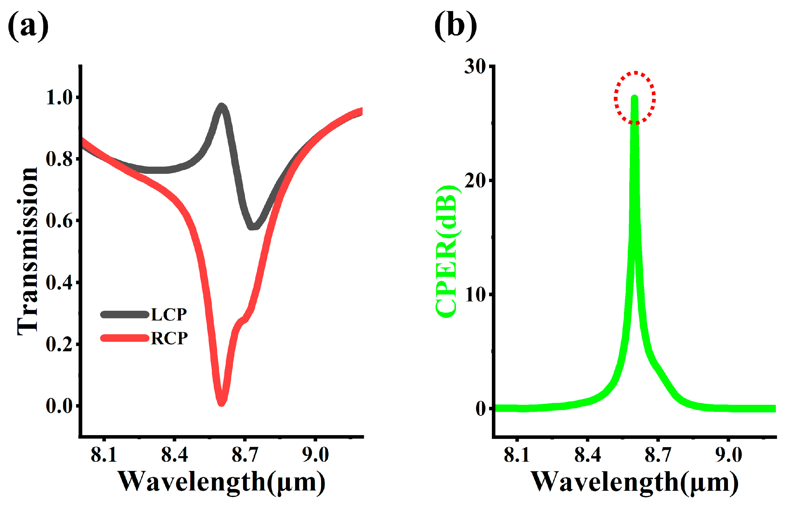
Figure 2a shows the transmission spectrum of the chiral metasurface in the wavelength range from 8.0 μm to 9.2 μm. In case of the LCP incidence, the transmission first increases, then decreases, and then increases again, with the maximum transmission of 0.97 corresponding to the operating wavelength of 8.6 μm. For RCP, there is a significant attenuation at the wavelength of 8.6 μm, and the transmission is already close to 0. Clearly, near the wavelength of 8.6 μm, the chiral metasurface exhibits distinct transmission characteristics for different chiral circularly polarized light. As shown in Figure 2b, the circular polarization extinction ratio (CPER) spectrum of the silicon metasurface filter shows the characteristics of a Dirac function. At the wavelength near 8.6 μm, CPER is a sharp peak, and on both sides far from the 8.6 μm wavelength, the value of CPER rapidly approaches 0. Here, C P E R = 10 × l o g ( T L C P / T R C P ) , where T L C P and T R C P are the transmission of the chiral metasurface for LCP and RCP, respectively.

3.1. The Influence of Geometric Structures in Metasurfaces

Generally, the geometric structure of the unit cell of the metasurface can directly determine the peak position, line shape and intensity of the circular dichroism (CD) spectrum, and its asymmetric parameters (such as displacement Δx, tilt angle θ) have a close mapping relationship with the CD value. Figure 3a–d, respectively, show the influence of the geometric changes in the unit cell of the chiral metasurface on the CD spectrum, where C D = T L C P T R C P . Figure 3a shows the case where the unit cell of the metasurface is two aligned rectangles, which is a typical C2 symmetric structure. Figure 3e shows the CD spectrum of the metasurface corresponding to the structure in Figure 3a, which is a constant zero, reflecting the fact that the unit cell of the metasurface is a non-chiral symmetric structure. Compared with Figure 3a,b introduces a horizontal displacement dx, which makes the unit cell of the metasurface transition from a non-chiral symmetric structure to a chiral symmetric structure. Figure 3f shows the CD spectrum of the geometric structure in Figure 3b, which presents a typical double-hump function spectrum shape, with the maximum CD peak value being approximately 0.2. In Figure 3c, triangles are added to both sides of the rectangle, introducing the concept of a tilted structure. As shown in Figure 3g, a huge CD peak (>0.8) appears at a wavelength of 8.6 μm, indicating that the metasurface has acquired significant chiral symmetry after undergoing dual changes in displacement and tilt angle. The structures in Figure 3c,d satisfy the mirror symmetry relationship about the YZ plane, which means that the metasurface’s control over the transmission of chiral beams has been reversed; that is, the CD values at each wavelength in Figure 3g,h are opposite to each other.

3.2. Analysis of the Electric Field Distribution of Metasurfaces

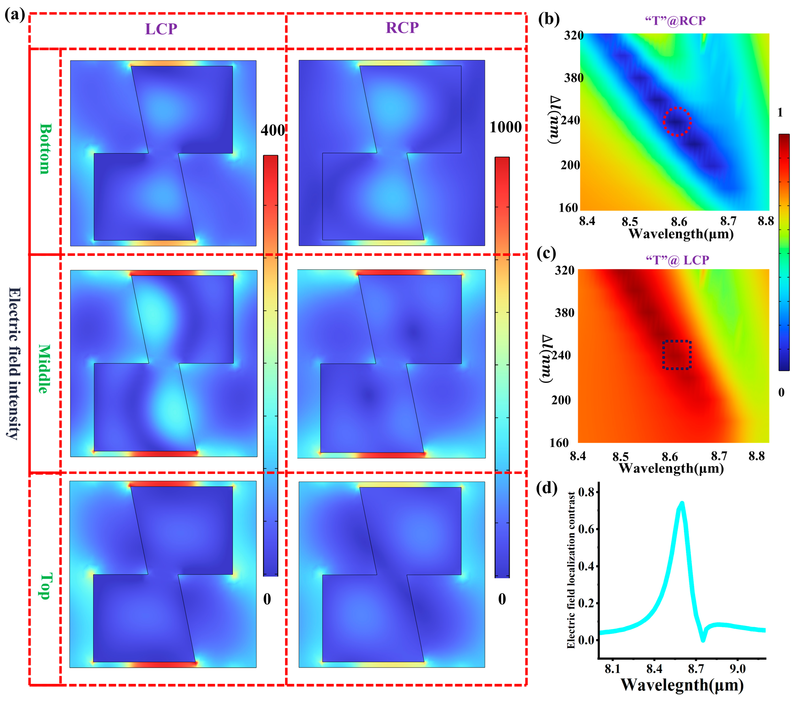
Observing the near-field intensity distribution of metasurfaces is also an effective means to analyze the optical resonance modes. Figure 4a shows the electric field intensity distribution of the metasurface on different XY cross-sections, all sharing the same color scale. All six sub-figures indicate a strong electric field localization phenomenon in the air gap between adjacent unit cells along the Y-axis, which is represented by the red areas in the images. Additionally, as shown in Figure 4b,c, there is a clear linear relationship between the length of the air gap, ∆l, and the incident wavelength, which exhibits the typical characteristics of the GMRs. The red dashed circles and black boxes, respectively, indicate the cases corresponding to the metasurface structure in Figure 1, which simultaneously correspond to the extremely high LCP transmission and extremely low RCP transmission. Figure 4d shows the electric field localization contrast (ELC) of the chiral metasurface for different chiral CPs, which quantitatively measures the concentration degree of the electromagnetic field energy in Figure 4a. The maximum ELC corresponds to a wavelength of 8.6 μm, indicating a direct correlation between the resonance wavelength and the distribution of electric field hotspots. Here, E L C = Q L C P Q R C P , Q L C P = | E L | E 0 d V / I m a x , Q R C P = | E R | E 0 d V / I m a x , where d V corresponds to the volume occupied by the metasurface. I m a x is the normalization term in the denominator and is the maximum value of | E L | E 0 d V . E0 corresponds to the electric field intensity of the incident light. EL and ER, respectively, correspond to the electric field intensities when the incident light is LCP and RCP.

3.3. The Influence of the Thickness of the Support Layer (hs)

In the previous sections, we focused on analyzing the transmission characteristics of chiral metasurfaces for different circularly polarized lights. In this subsection, we mainly discuss the influence of the thickness hs of the support layer (MgF2) between the chiral metasurface and the type-II superlattice photodetector on chirality. One fact must be noted, which is that we have pre-assumed the metasurface and the photodetector to be two independent sub-modules when designing the CPPD, so hs must be carefully scanned to ensure that the coupling effect between them is not a negative feedback. Figure 5a depicts the impact of hs on the CPPD at a wavelength of 8.6 μm. The absorption spectrum of LCP has a typical fluctuating characteristic, while the absorption spectrum of RCP first decreases and then remains basically unchanged. CPER is also a fluctuating curve, with the maximum CPER value corresponding to hs of 3.1 μm. Here, CPER = 10 × l o g ( A LCP / A RCP ) , where A LCP and A RCP are the absorption rate of the chiral metasurface filter for LCP and RCP, respectively. Figure 5b shows the absorption spectrum and CPER spectrum of the CPPD when hs = 3.1 μm. The maximum LCP absorption rate (≈0.33) and CPER value (≈28 dB) both occur at the operating wavelength of 8.6 μm. Figure 5c–f show the electric field distribution in the detector region under different CP incident conditions. It can be found that a large amount of electric field energy from the upper region penetrates into the absorption layer corresponding to LCP. However, in the case of RCP incidence, the upper metasurface acts like a perfect reflector, and almost no free photons can enter the absorption region, which is represented by the blue color indicating low electromagnetic energy in the picture.

3.4. Analysis of Potential Process Errors

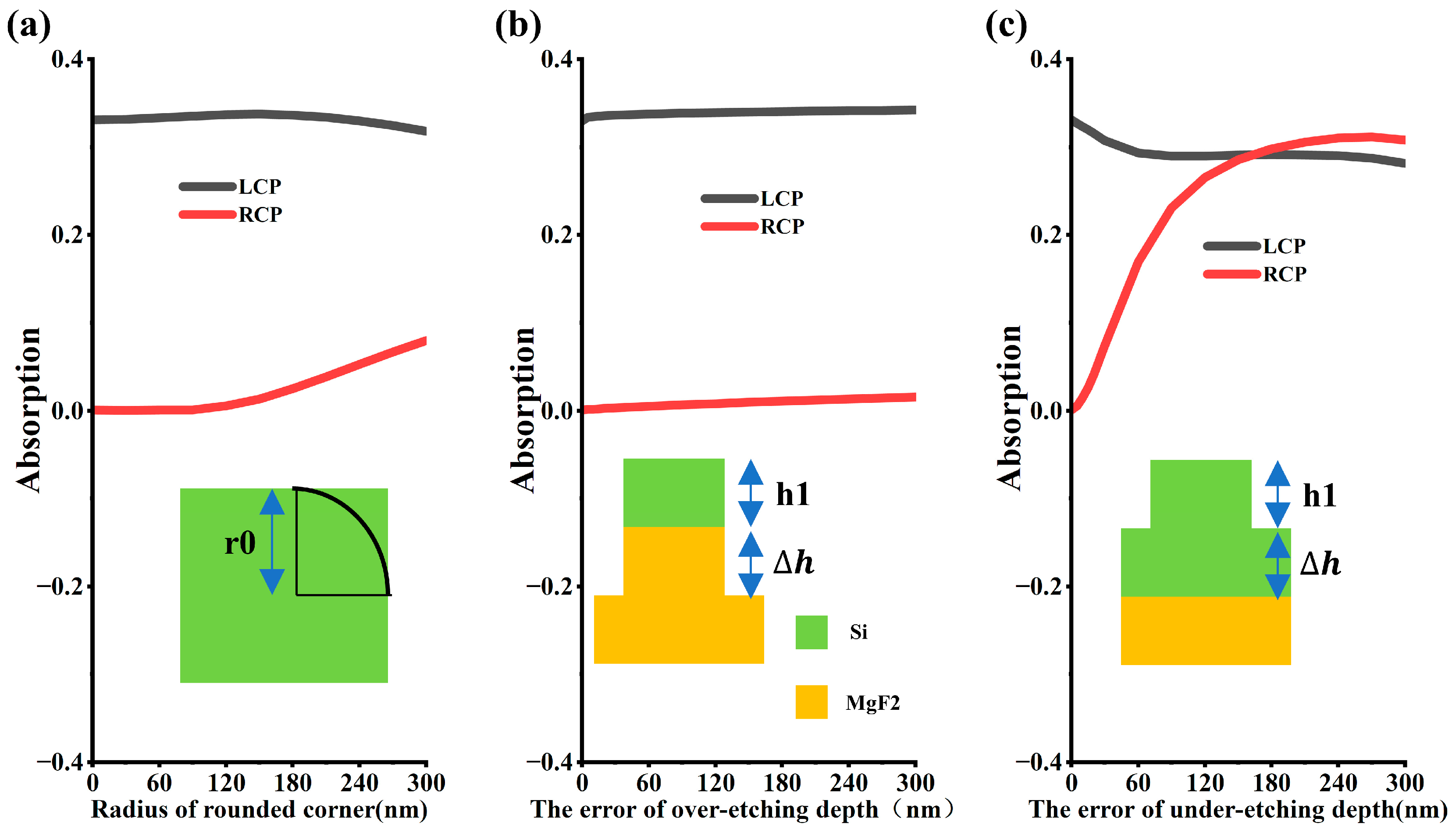
Since the chirality of the polarization detector is determined by the nanostructure pattern of the metasurface, the influence of line errors cannot be ignored. In semiconductor processing, it is impossible to achieve an ideal rectangle, and instead, a circular arc replaces the right angle of the rectangle. This is a result of the combined effects of photolithography diffraction, microloading during etching, and the natural tendency of surface energy minimization. Figure 6a shows the influence of the radius of the inscribed circle in the silicon metasurface on the polarization detector. When the radius is less than 100 nm, the absorption rates of LCP and RCP remain almost unchanged. When the radius is greater than 100 nm, the two absorption rates approach each other as the radius increases. Additionally, over-etching and under-etching phenomena are often encountered during semiconductor etching, and the resulting etching depth errors also require additional attention. The inset in Figure 6b shows the over-etching phenomenon, where not only is the silicon completely etched away, but also the underlying substrate material is patterned. As shown in Figure 6b, the change caused by the etching error ∆h is weak. However, a completely different phenomenon occurs in Figure 6c. For LCP, when the current etching error ∆h is within the range of 0 nm to 60 nm, the absorption rate decreases significantly as ∆h increases. When ∆h is greater than 60 nm, the absorption rate remains almost unchanged. Moreover, for RCP, the absorption rate increases as ∆h increases. When ∆h equals 150 nm, the absorption rates of RCP and LCP are the same, indicating that the detector has lost its chiral detection capability. Therefore, it is very necessary to intentionally over-etch for a few more seconds during etching to guarantee that the etching process unequivocally reaches the over-etching state. Table 1 presents the performance of some chiral metasurfaces published in the recent two years. It can be found that the CD and CPER of the metasurfaces in the manuscripts are both excellent. Particularly for the CPER index, our work has basically led by one order of magnitude.

4. Discussion

We have developed a novel CPPD capable of direct chiral discrimination in free-space optical systems, comprising a silicon-based chiral metasurface integrated with a type-II superlattice photodetector. By precisely engineering the air gap dimension (Δl) between adjacent meta-atoms, our device achieves near 100% CD at the operational wavelength of 8.6 μm through excitation of optimized GMRs modes. This CPPD scheme provides access to the chirality of photons—a critical light parameter that remains inaccessible to conventional intensity-based photodetectors, thereby opening new possibilities in quantum optics and interdisciplinary applications. Future research directions will focus on two key aspects, namely (1) bandwidth enhancement to enable spectrally broadband operation and (2) integration of chiral metasurfaces with dual-color or multicolor detection systems, to simultaneously achieve multi photon acquisition and polarization-resolved measurements.

Supplementary Materials

The following supporting information can be downloaded at https://www.mdpi.com/article/10.3390/cryst15110993/s1. Figure S1: (a): XZ cross-sectional view of the COMSOL model of the chiral metasurface. (b): XZ cross-sectional view of the COMSOL model of the circularly polarized photodetector. Figure S2: Basic Structure of TEC.

Author Contributions

Conceptualization, B.C. and Y.Z.; methodology, A.Y.; software, B.C.; validation, B.C., Y.Z. and K.Z.; formal analysis, A.Y.; investigation, T.L.; resources, K.Z.; data curation, L.L.; writing—original draft preparation, B.C.; writing—review and editing, K.Z.; visualization, K.Z.; supervision, K.Z.; project administration, L.L.; funding acquisition, K.Z. All authors have read and agreed to the published version of the manuscript.

Funding

This research was funded by the Natural Science Foundation of Tianjin, grant number No. 24JCQNJC01880; This research was funded by the Research on Optoelectronic Fusion Technology, ZB253015; This research was funded by the Young Elite Scientists Sponsorship Program of Cast, grant number No. YESS20240775; This research was funded by the Strategic Priority Research Program of the Chinese Academy of Sciences (grant no. XDB0980000).

Data Availability Statement

The raw data supporting the conclusions of this article will be made available by the authors on request.

Acknowledgments

The authors are grateful to Jietao Liu, Hanxiao Shao and GuoFeng Song of Institute of Semiconductors, Chinese Academy of Sciences.

Conflicts of Interest

The authors declare no conflicts of interest.

References

  1. Smith, W.H.; Born, J.; Cochran, W.D.; Gelfand, J. Spectroscopic photoelectric imaging Fabry-Perot interferometer—Its development and preliminary observational results. Appl. Opt. 1976, 15, 717–724. [Google Scholar] [CrossRef]
  2. Pathak, A. Elements of Quantum Computation and Quantum Communication; Taylor & Francis: Abingdon, UK, 2013. [Google Scholar]
  3. King, M.D.; Kaufman, Y.J.; Tanré, D.; Nakajima, T. Remote sensing of tropospheric aerosols from space: Past, future and present. Bull. Am. Meteorol. Soc. 1999, 80, 2229–2259. [Google Scholar] [CrossRef]
  4. Rudolph, W.; Kempe, M. Trends in optical biomedical imaging. Opt. Acta Int. J. Opt. 1997, 44, 1617–1642. [Google Scholar] [CrossRef]
  5. Sambles, J.R. Polarized Light in Optics and Spectroscopy. Opt. Acta Int. J. Opt. 1991, 38, 1204–1205. [Google Scholar] [CrossRef]
  6. Liu, Y.; Ling, X.; Yi, X.; Zhou, X.; Luo, H.; Wen, S. Realization of polarization evolution on higher-order Poincare sphere with metasurface. Appl. Phys. Lett. 2014, 104, 191110. [Google Scholar] [CrossRef]
  7. Wei, Z.; Cao, Y.; Su, X.; Gong, Z.; Li, H. Highly efficient beam steering with a transparent metasurface. Opt. Express 2013, 21, 10739–10745. [Google Scholar] [CrossRef] [PubMed]
  8. Arbabi, A.; Arbabi, E.; Horie, Y.; Kamali, S.M.; Faraon, A. Planar metasurface retroreflector. Nat. Photonics 2017, 11, 415–420. [Google Scholar] [CrossRef]
  9. Liu, C.; Wang, H.; Zhao, R.; Lei, Y.; Dong, S.; Cai, Y.; Zhou, W.; Wang, Y.; Huang, L.; Xu, K.M. Multi-plane vectorial holography based on a height tunable metasurface fabricated by femtosecond laser direct writing. Photonics Res. 2024, 12, 8. [Google Scholar] [CrossRef]
  10. Li, S.; Chen, C.; Wang, G.; Ge, S.; Zhao, J.; Ming, X.; Zhao, W.; Li, T.; Zhang, W. Metasurface Polarization Optics: Phase Manipulation for Arbitrary Polarization Conversion Condition. Phys. Rev. Lett. 2025, 134, 023803. [Google Scholar] [CrossRef] [PubMed]
  11. Li, Z.; Liu, W.; Cheng, H.; Chen, S.; Tian, J. Tunable dual-band asymmetric transmission for circularly polarized waves with graphene planar chiral metasurfaces. Opt. Lett. 2016, 41, 3142–3145. [Google Scholar] [CrossRef] [PubMed]
  12. Ma, C.; Yu, P.; Jing, Z.; Zhu, Y.; Li, P.; Wang, W.; Xu, H.; Zhang, Y.; Pan, L.; Choi, T.-Y.; et al. Circular polarization-selective optical, photothermal, and optofluidic effects in chiral metasurfaces. Photonics Res. 2024, 12, 331. [Google Scholar] [CrossRef]
  13. Jang, J.; Park, M.; Park, Y. Non-interleaved chiral metasurfaces and neural networks enhance the spatial resolution of polarimetry. Light Sci. Appl. 2024, 13, 53. [Google Scholar] [CrossRef]
  14. Wang, C.; Cheng, X.; Wang, R.; Hu, X.; Wang, C. Flexibly Designable 2D Chiral Metasurfaces with Pixelated Topological Structure Based on Machine Learning. Laser Photonics Rev. 2024, 18, 2300958. [Google Scholar] [CrossRef]
  15. Gromyko, D.; Loh, J.S.; Feng, J.; Qiu, C.W.; Wu, L. Enabling All-to-Circular Polarization Up-Conversion by Nonlinear Chiral Metasurfaces with Rotational Symmetry. Phys. Rev. Lett. 2025, 134, 023804. [Google Scholar] [CrossRef]
  16. Stephens, P.J.; Devlin, F.J.; Chabalowski, C.F.; Frisch, M.J. Ab Initio Calculation of Vibrational Absorption and Circular Dichroism Spectra Using Density Functional Force Fields. J. Phys. Chem. 1994, 98, 247–257. [Google Scholar] [CrossRef]
  17. Greenfield, N.J.; Fasman, G.D. Computed circular dichroism spectra for the evaluation of protein conformation. Biochemistry 1969, 8, 4108. [Google Scholar] [CrossRef] [PubMed]
  18. Berova, N.; Nakanishi, K.; Woody, R.W. Circular Dichroism: Principles and Applications. In Circular Dichroism Principles Applications; John Wiley & Sons: Hoboken, NJ, USA, 2000. [Google Scholar]
  19. Zhang, R.; Zhang, Z.; Fan, Y.; Zhang, H.; Chu, J. Single-Layer Transmissive Chiral Plasma Metasurface with High Circular Polarization Extinction Ratio in Visible Wavelength. Nanomaterials 2023, 13, 813. [Google Scholar] [CrossRef]
  20. Ye, Y.; Li, X.; Zhuang, F.; Chang, S.W. Homogeneous circular polarizers using a bilayered chiral metamaterial. Appl. Phys. Lett. 2011, 99, 031111. [Google Scholar] [CrossRef]
  21. Cheng, B.; Zou, Y.; Song, G. Full-Stokes polarization short-wave infrared photodetector based on the doubly regulated dielectric metasurfaces. Optik 2025, 322, 172198. [Google Scholar] [CrossRef]
  22. Tang, Y.; Xie, B.; Liu, H.; Zhang, Y.; Cheng, H.; Chen, S. Mirror Symmetry Broken of Sound Vortex Transmission in a Single Passive Metasurface via Phase Coupling. Phys. Rev. Lett. 2024, 132, 6. [Google Scholar] [CrossRef] [PubMed]
  23. Shen, Z.; Huang, D.; Lin, X. Dual-band chirality-selective absorbing by plasmonic metasurfaces with breaking mirror and rotational symmetry. Opt. Express 2023, 31, 12. [Google Scholar] [CrossRef]
  24. Petronijevic, E.; Cesca, T.; Scian, C.; Mattei, G.; Voti, R.L.; Sibilia, C.; Belardini, A. Demonstration of extrinsic chirality in self-assembled asymmetric plasmonic metasurfaces and nanohole arrays. Sci. Rep. 2024, 14, 17210. [Google Scholar] [CrossRef]
  25. Levanon, N.; Indukuri, S.C.; Frydendahl, C.; Bar-David, J.; Han, Z.; Mazurski, N.; Levy, U. Angular Transmission Response of In-Plane Symmetry-Breaking Quasi-BIC All-Dielectric Metasurfaces. ACS Photonics 2022, 9, 3642–3648. [Google Scholar] [CrossRef]
  26. Gordon, I.E.; Rothman, L.S.; Hargreaves, R.J.; Hashemi, R.; Karlovets, E.V.; Skinner, F.M.; Conway, E.K.; Hill, C.; Kochanov, R.V.; Tan, Y.; et al. The HITRAN2020 molecular spectroscopic database. J. Quant. Spectrosc. Radiat. Transf. 2022, 277, 107949. [Google Scholar] [CrossRef]
  27. Beer, R. TES on the aura mission: Scientific objectives, measurements, and analysis overview. IEEE Trans. Geosci. Remote Sens. 2006, 44, 1102–1105. [Google Scholar] [CrossRef]
  28. Brown, G.J.; Szmulowicz, F.; Linville, R.; Saxler, A.; Mahalingham, K.; Lin, C.H.; Kuo, C.H.; Hwang, W.Y. Type-II superlattice photodetector on a compliant GaAs substrate. IEEE Photonics Technol. Lett. 2002, 12, 684–686. [Google Scholar] [CrossRef]
  29. Koyama, M.; Kudo, J.; Iguchi, Y.; Inada, H.; Muramatsu, Y.; Kumihashi, I.; Sano, M. Indium Gallium Arsenide/Gallium Arsenide Antimonide Type II Superlattice Photodetector That Can Utilize Night Airglow. Sens. Mater. 2024, 36, 2183–2197. [Google Scholar]
  30. Wu, Y.; Li, J.; Zhang, Z.Q.; Chan, C.T. Effective medium theory for magnetodielectric composites: Beyond the long-wavelength limit. Phys. Rev. 2006, B74, 085111, Erratum in Phys. Rev. 2015, B92, 199901. [Google Scholar] [CrossRef]
  31. Chang, L.; Ho, C.C.; Wei, H.S.; Wu, G.Y. Effective medium theory with dimensionality reduction for band structures of photonic crystals. J. Appl. Phys. 2007, 101, 2059. [Google Scholar] [CrossRef]
  32. Gao, Z.; Wang, P.; Xu, Z.; Zhao, T. Chiral metasurface absorber with near-infrared excitation-induced dual circular dichroism. Opt. Laser Technol. 2024, 175, 110826. [Google Scholar] [CrossRef]
  33. Toftul, I.; Tonkaev, P.; Koshelev, K.; Lai, F.; Song, Q.; Gorkunov, M.; Kivshar, Y. Chiral Dichroism in Resonant Metasurfaces with Monoclinic Lattices. Phys. Rev. Lett. 2024, 133, 216901. [Google Scholar] [CrossRef] [PubMed]
  34. Sun, Y.; He, C.; Deng, Z.; Li, X.; Li, X.; Zhang, Z.; Sui, X.; Li, N.; He, W.; Chen, F. Optical chirality of all dielectric q-BIC metasurface with symmetry breaking. Nanophotonics 2025, 14, 559–569. [Google Scholar] [CrossRef] [PubMed]
  35. Wang, G.; Zhang, X.; Liu, J.; Feng, H.; Li, M.; Yang, S.; Jia, Y.; Meng, H.; Gao, Y. A multifunction tunable terahertz chiral metasurface based on graphene and photosensitive silicon. Opt. Mater. 2024, 150, 115177. [Google Scholar] [CrossRef]
  36. Raza, F.; Chen, R.; Ma, Y. Fano-modulated chiral metasurface for near-infrared sensing via bound states in the continuum. J. Appl. Phys. 2024, 136, 243103. [Google Scholar] [CrossRef]
  37. Han, J.; Jang, H.; Lim, Y.; Kim, S.; Lee, J.; Jun, Y.C. Chiral Emission from Optical Metasurfaces and Metacavities. Adv. Photonics Res. 2024, 5, 2400060. [Google Scholar] [CrossRef]
  38. Asefa, S.A.; Seong, M.; Lee, D. Design of Bilayer Crescent Chiral Metasurfaces for Enhanced Chiroptical Response. Sensors 2025, 25, 915. [Google Scholar] [CrossRef] [PubMed]
Figure 1. The structure and materials of micro-devices. (a) A circularly polarized type-II superlattice photodetector operating at a wavelength of 8.6 μm; (b) Three-dimensional structure of chiral metasurface. The h1 = 5.59 μ m, h2 = 3.1 μ m. (c) The XY cross-sectional view of the unit cell of the metasurface. The px = py = 4 μ m, a0 = 2.19 μ m, a1 = 0.64 μ m, a2 = 1.17 μ m, a3 = 1.88 μ m. (d) The imaginary part of the optical refractive index of the absorption region in a type-II superlattice photodetector. The orange cross cursor corresponds to 8.6 μ m, which is a characteristic wavelength for monitoring the concentration and distribution of ozone in the atmosphere [30,31].
Crystals 15 00993 g001
Figure 2. Transmission characteristics of the chiral metasurface. (a) Transmission spectra of circularly polarized light; (b) CPER spectra. The red dotted circle corresponds to the CPER at the operating wavelength.
Crystals 15 00993 g002
Figure 3. The influence of geometric operations. (a) Two aligned rectangles; (b) Two rectangles with a horizontal dislocation dx; (c) The combination of the rectangle and the triangle; (d) The mirror image pattern of Figure 3c in the YZ plane. The colored dotted lines correspond to the boundaries of the structures located above the long strips in the unit cell; (e) The CD spectrum corresponding to Figure 3a; (f) The CD spectrum corresponding to Figure 3b; (g) The CD spectrum corresponding to Figure 3c; (h) The CD spectrum corresponding to Figure 3d.
Crystals 15 00993 g003
Figure 4. The distribution of the electric field of the metasurface and the GMRs. (a) Electric field distribution on the XY cross-section of the metasurface. “Bottom”, “Middle”, and “Top” correspond to the positions of the XY cross-section at the bottom, middle, and top of the metasurface, respectively; (b,c) The influence of the air gap length ∆l on the transmission spectrum; (d) The difference in the localization of the electric field in the LCP and RCP cases. The dashed circles and boxes correspond to the transmittance at the operating wavelength.
Crystals 15 00993 g004
Figure 5. (a) The influence of the thickness of the supporting layer hs on the absorption of the left circularly polarized photodetector at an operating wavelength of 8.6 μm; (b) The absorption spectrum and CPER spectrum of the polarization detector corresponding to the optimal hs, The plus sign corresponds to the position of the peak; (c) The electric field distribution diagram of the CPPD under LCP incidence in the XZ cross-section; (d) The electric field distribution diagram of the CPPD under RCP incidence in the XZ cross-section; (e) The electric field distribution diagram of the CPPD under LCP incidence in the YZ cross-section; (f) The electric field distribution diagram of the CPPD under RCP incidence in the YZ cross-section.
Crystals 15 00993 g005
Figure 6. The influence of potential process errors. (a) Radius of the fillet. (b) Error of over-etching depth. (c) Error of under-etching depth. Green represents silicon.
Crystals 15 00993 g006
Table 1. A comparison of the performance of chiral metasurfaces.
StructurePublicationWavelength (μm)CDCPER (dB)
π-shaped [32]20241.55, 2.550.7, 0.75~10, ~10
Monoclinic Lattices [33]20241.60.3/
Broken circle [34]20251.350.17/
Graphene and silicon [35]20242500.99
Double Si columns [36]20241.01~0.96
Swastika-shaped [37]20240.530.263
Double-layered gold [38]20251.250.55~8
This work 8.6~127
Disclaimer/Publisher’s Note: The statements, opinions and data contained in all publications are solely those of the individual author(s) and contributor(s) and not of MDPI and/or the editor(s). MDPI and/or the editor(s) disclaim responsibility for any injury to people or property resulting from any ideas, methods, instructions or products referred to in the content.