3.1. Microstructure and Elemental Gradient
Comparison of the parameters of the preliminary mechanical treatment showed that the optimal mode should provide a compromise between the reduction in surface roughness and the increase in microhardness, both necessary for stable microarc ignition and accelerated nitrogen diffusion during EPN (
Table 1). Compared to the initial surface (Ra = 3.93 μm; HV = 236), the best balance is achieved in three optimal modes: sample 3 (d = 6 mm, t = 20 min, v = 40 Hz, filling 80%), which provides the minimum roughness Ra = 2.05 μm with high microhardness HV = 497.8; sample 6 (d = 6 mm, t = 20 min, v = 50 Hz), where a moderate Ra = 2.54 μm is accompanied by increased work hardening HV = 514.6; and sample 8 (d = 7.5 mm, t = 20 min, v = 40 Hz), demonstrating a combination of Ra = 3.03 μm and the maximum HV = 515.6 among the selected modes, reflecting the higher impact energy of larger balls. The remaining variants are inferior in terms of combined criteria: for example, increasing the treatment time to 30 min (sample 5) yields a peak hardness of HV = 574.9 but is accompanied by an unacceptable increase in roughness (Ra = 4.96 μm), while reducing the frequency to 30 Hz (sample 7) worsens both parameters. Therefore, for subsequent electrolytic-plasma nitriding, samples 3, 6, and 8 were selected as the most appropriate, providing a smooth yet work-hardened surface (Ra ≈ 2.0–3.0 μm; HV ≈ 500–516), favorable for uniform microarc discharge and the formation of a high-quality nitride layer.
In
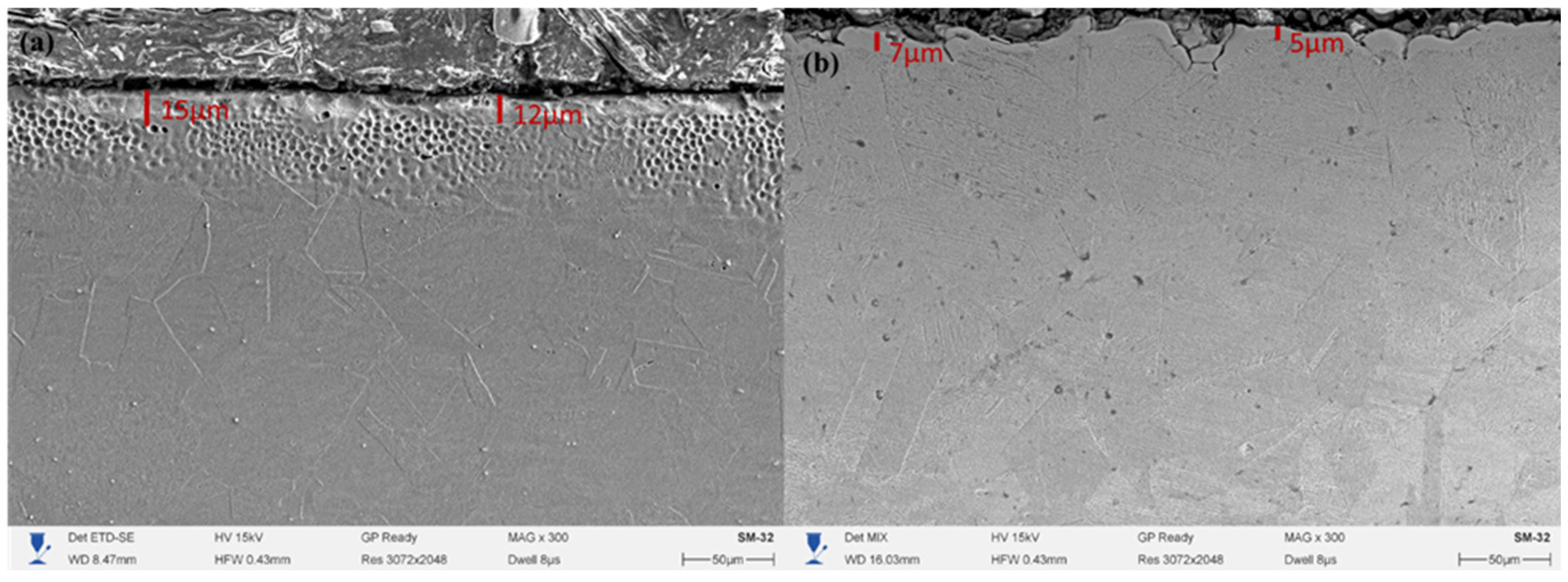
Figure 4a, a uniform and dense surface layer with a thickness of about 12–15 μm is observed, corresponding to the expanded austenite (γN) zone. The structure is characterized by uniform contrast, absence of pores and nitride phase precipitates, indicating a metastable solid solution of nitrogen in the γ-Fe lattice. The surface of the layer exhibits a more developed morphology with rounded craters caused by microplasma discharges, but without signs of overheating or local melting. The formation of a thicker γN layer after mechanical treatment is associated with an increased defect density of the crystal lattice and a higher dislocation density, which facilitates nitrogen diffusion into the metal. Similar results were reported in studies [
25,
26], where mechanical surface strengthening prior to nitriding promoted accelerated growth of expanded austenite.
In contrast, in
Figure 4b, for the sample without preliminary mechanical treatment, the thickness of the hardened layer is only 5–7 μm, while the structure is less contrasted and contains individual microdefects along the layer boundary. The absence of active diffusion centers and the lower surface energy limit nitrogen penetration, leading to the formation of a thinner γN zone. A slight inhomogeneity is also observed in the near-surface region, indicating local variations in the plasma exposure intensity. Mechanical surface treatment prior to electrolytic-plasma nitriding has a significant effect on the nitrogen diffusion kinetics and the thickness of the formed hardened layer. The increase in the γN zone thickness to 12–15 μm after preliminary work hardening is explained by the higher number of crystal lattice defects and the formation of a substructure that facilitates accelerated interstitial nitrogen penetration.
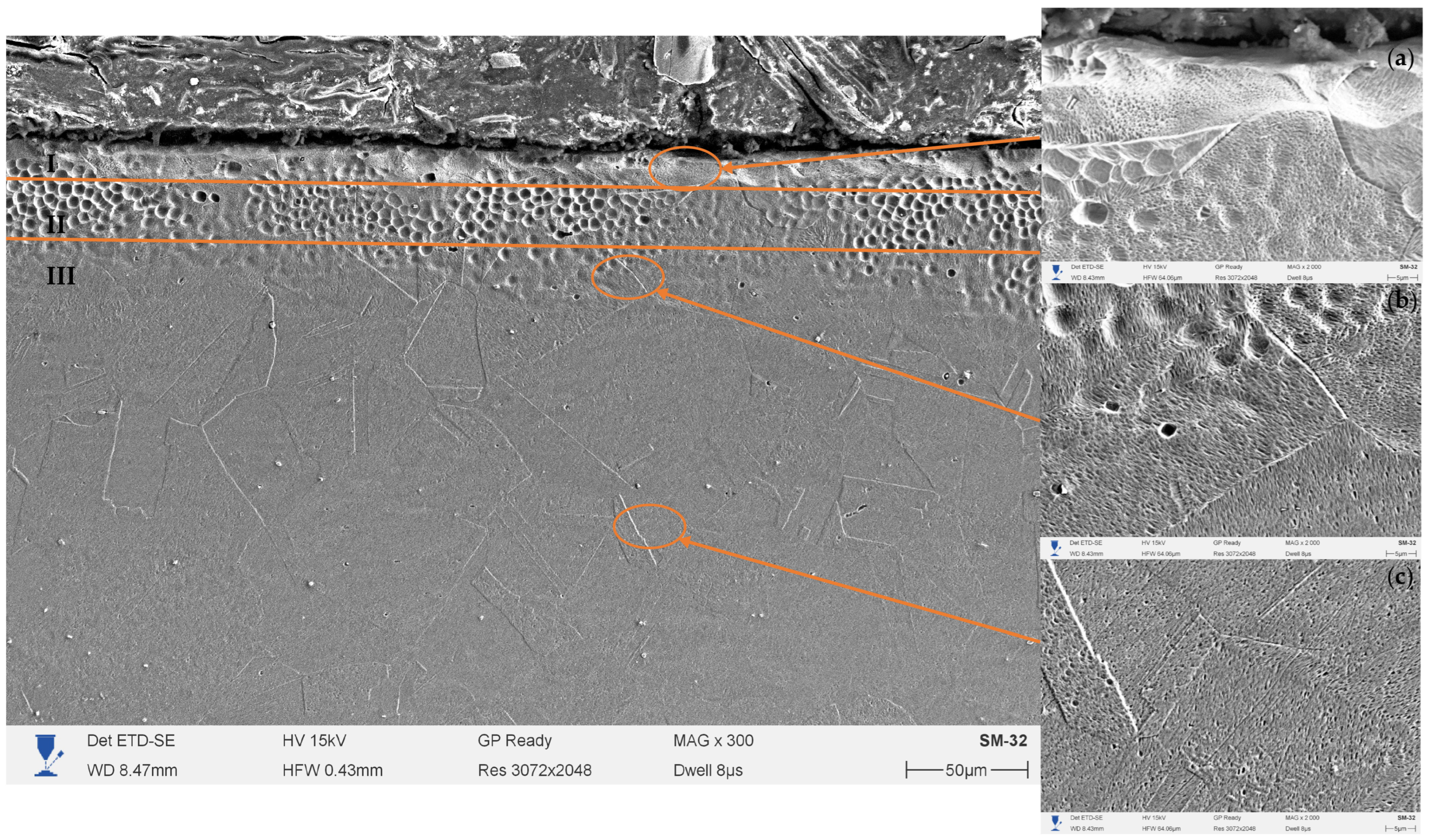
Figure 5 shows the SEM microstructure of the cross-section of 12Kh18N10T (AISI 321) steel after preliminary mechanical surface treatment and subsequent electrolytic-plasma nitriding at a temperature of 500 °C, voltage of 180 V, and duration of 10 min. The microstructure of the hardened layer exhibits a clearly defined zonal morphology and consists of three regions: I—nitride zone, II—transition zone, and III—initial austenitic structure. Detailed images of these zones at ×2000 magnification are shown in fragments (a–c).
The upper part of the layer (zone I) is represented by a dense and continuous near-surface structure about 1–2 μm thick, exhibiting increased contrast. This zone is characterized by the formation of a thin nitride film containing fine-dispersed chromium and iron particles (CrN, Fe4N), which are formed as a result of surface supersaturation with active nitrogen ions. The uniformity and absence of pores indicate the stability of the plasma discharge and the uniformity of nitriding in the near-surface region. Such microstructural features are typical of low-temperature electrolytic-plasma saturation modes, where intense surface interaction occurs without significant melting or metal erosion.
Beneath the surface nitride zone lies the transition zone (II), about 10–15 μm thick, which constitutes the main hardened region. Here, the expanded austenite (γN) phase is formed—a metastable solid solution of nitrogen in the γ-Fe lattice, free from chromium nitride precipitates. The microstructure of this zone is characterized by fine grains and uniform contrast, reflecting the high defect density of the crystal lattice and the presence of significant internal compressive stresses. Such features are caused by the interstitial incorporation of nitrogen atoms, which leads to an increase in the lattice parameter and the formation of expanded austenite. The observed subgrain boundaries and characteristic diffusion flow lines in micrographs (b) indicate active atomic migration processes in the near-surface region. The thickness of this zone is consistent with the results obtained at similar temperatures in studies [
27,
28], where the formation of a γN structure without CrN precipitates was also observed at temperatures up to 550 °C. During EPN, microdischarges are localized at the protrusions of the surface microrelief and produce short-term local melting/boiling; when polished across this zone, such craters are cut and appear as rounded dark cavities with a diameter of about 0.5–2 µm, arranged in a band parallel to the surface. Below in depth (region III), the matrix without pores is observed, showing characteristic slip traces.
Below lies zone III, corresponding to the original austenitic structure. It is characterized by a coarse-grained morphology, low contrast, and the absence of phase transformations. The transition between layers II and III is gradual, confirming the diffusion nature of the hardened layer formation and the good metallurgical bonding of the modified zone with the substrate. Residual traces of plastic deformation caused by mechanical treatment are observed in this region; however, they do not compromise the integrity of the layer.
A comparison of the zone structures allows the conclusion that preliminary mechanical surface treatment significantly enhances the nitriding processes. The increased dislocation density, along with the presence of microrelief and microcracks after treatment, creates additional pathways for interstitial nitrogen diffusion, promoting the growth of the γN zone and a more uniform nitrogen distribution with depth. As a result, a multilayer system is formed: a thin nitride film, a developed expanded austenite region, and a stable austenitic substrate. Such a combination provides an optimal balance between high surface hardness, adhesion, and preservation of corrosion resistance.
In
Figure 5, the SEM study of the cross-section of 12Kh18N10T (AISI 321) steel after electrolytic-plasma nitriding shows a clearly pronounced zonal structure, indicating the diffusion nature of saturation. In the near-surface region, a dense, porous-granular layer with pronounced contrast is observed, corresponding to the γN-phase of supersaturated austenite. Deeper in the layer, the structure gradually becomes more homogeneous, with a decrease in the number of micropores and dislocation accumulations, indicating a transition to the sublayer of deformed γ-austenite and further to the original γ-matrix. Such a gradient structure of the layer confirms the diffusion mechanism of nitrogen incorporation during electrolytic-plasma treatment and the preservation of a smooth structural transition between the hardened zone and the substrate, which ensures high adhesion strength of the coating.
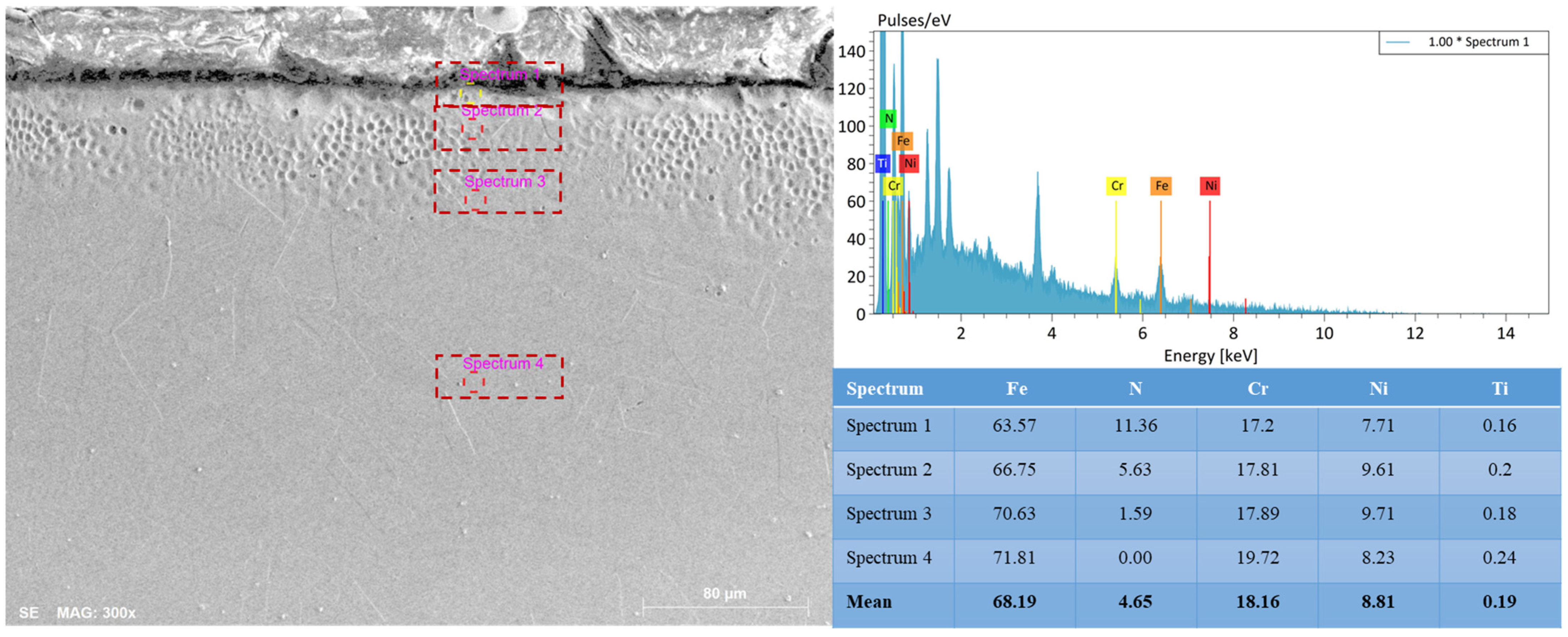
The results of the EDS analysis (
Figure 6) show a gradual decrease in nitrogen concentration from 11.36 at.% at the surface to 1.6 at.% at a depth of ~10–12 µm, and its almost complete absence in the core. At the same time, the proportion of iron and chromium increases, while the content of nickel and titanium remains stable. The obtained data indicate the formation of a stable chemical and structural gradient characteristic of low-temperature nitriding. The high nitrogen content in the near-surface zone leads to an expansion of the γ-phase lattice parameter and an increase in microhardness, while the gradual decrease in concentration toward the substrate prevents the formation of brittle CrN nitrides. Thus, the developed nitrogen distribution gradient confirms the effectiveness of the selected EPN mode and its compliance with the optimal conditions for the formation of functional γN layers with enhanced wear and corrosion resistance.
According to SEM data (
Figure 4 and
Figure 5), the structure of the modified layer exhibits a multilayer configuration typical of low-temperature EPN:
surface nitride film 1–2 µm thick (CrN/Fe4N),
transition zone 10–15 µm thick consisting of expanded austenite (γN),
stable γ-Fe substrate.
The transition zone is characterized by a fine-grained structure and high contrast, indicating intense lattice distortions. The Cr and Ni contents remain virtually unchanged, confirming the absence of local chromium depletion that could impair corrosion resistance. Such a distribution ensures a smooth transition of mechanical properties and high adhesion between the modified layer and the base metal. As seen from the elemental distribution profile, the nitrogen concentration decreases from 17 at.% at the surface to less than 1 at.% at a depth of 20 µm, which corresponds to a diffusion saturation mechanism. However, the EDS method has limited sensitivity to low atomic number elements and does not allow detailed visualization of local enrichment and depletion regions. In a recent study [
29], it was shown that the use of EPMA provides high spatial resolution for elemental distribution mapping. In future work, EPMA is planned to be used to refine the structure of the γN layer.
3.2. Phase Evolution During EPN
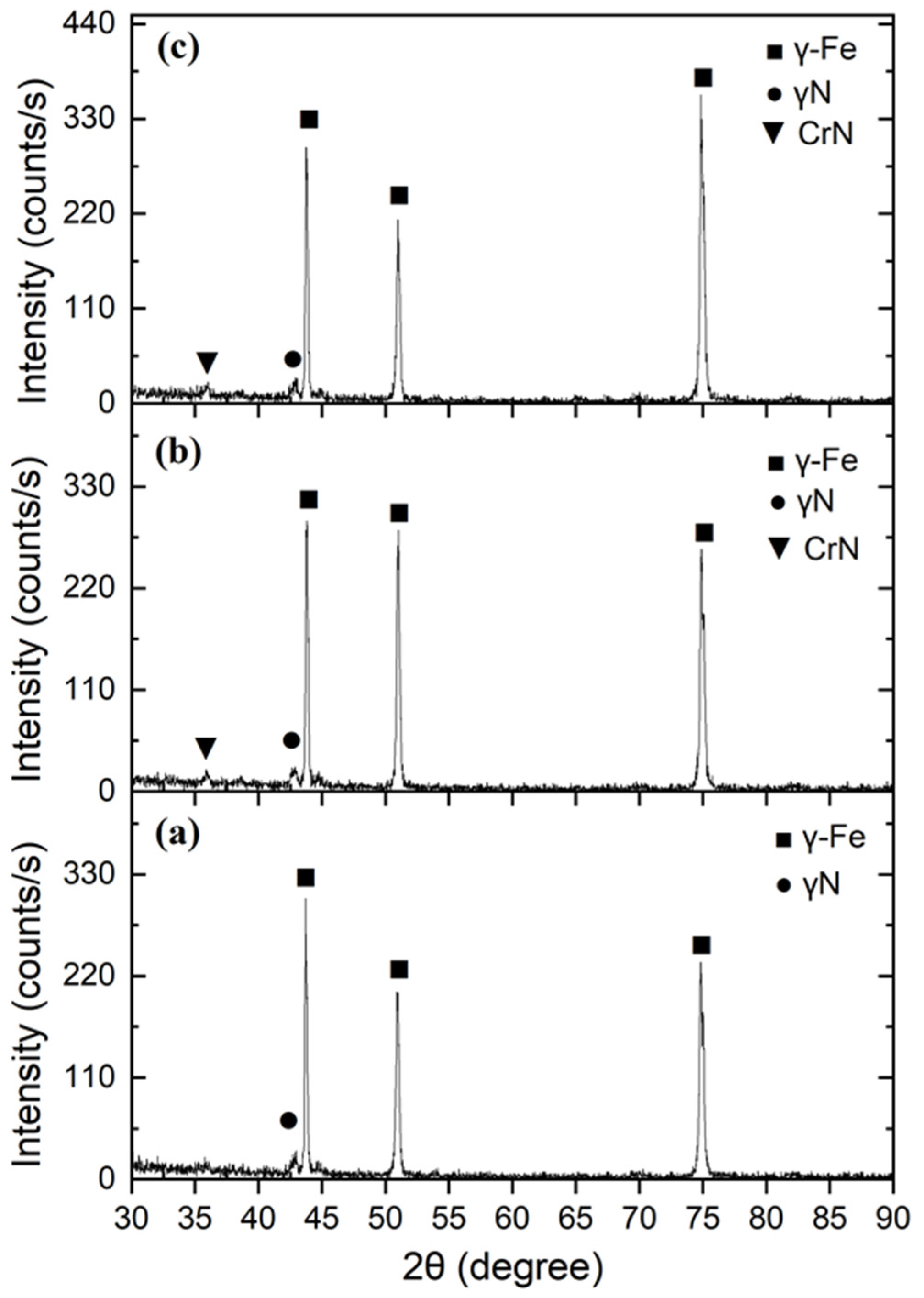
X-ray phase analysis shows that in all cases the matrix retains its austenitic FCC structure: intense γ-Fe reflections are observed at 2θ ≈ 43°, 50°, and 74°, corresponding to the (111), (200), and (220) planes. At the low-angle side of the (111) peak, a broadened shoulder is observed in the region of 2θ ≈ 41–42°, which is characteristic of expanded austenite γN (S-phase), formed as a result of supersaturation of the γ-Fe lattice with nitrogen atoms. For sample 3 (
Figure 7a), the γ-Fe peaks remain sharp, and the γN shoulder is weakly expressed; nitride phases such as CrN are absent. This indicates the predominance of nitrogen in solid solution and the formation of a stable single-phase γ-Fe(N) structure without chromium nitride precipitates. Such an X-ray pattern indicates a uniform nitrogen distribution under limited saturation, which is typical for moderate surface work hardening that creates optimal conditions for diffusion without local supersaturation. In sample 8 (
Figure 7b), the γN shoulder becomes more pronounced, and a weak CrN (111) reflection appears in the region of 2θ ≈ 37°. The increase in the γN peak intensity reflects a higher degree of nitrogen incorporation into the γ-Fe lattice, while the appearance of the nitride phase indicates the onset of local CrN precipitation under increased surface defect density. Such behavior is associated with the larger ball size used during mechanical treatment (d = 7.5 mm), which promotes deeper work hardening and increases dislocation density, thereby accelerating nitrogen diffusion into the metal.
The most pronounced changes were recorded for sample 6 (
Figure 7c), which was treated at an increased vibration frequency (v = 50 Hz). The γN peak becomes more intense and shifts toward lower angles, indicating a significant lattice parameter expansion due to the high concentration of interstitial nitrogen. At the same time, a weak appearance of CrN (111) is observed, with its intensity remaining significantly lower than that of the γ-Fe peaks. This indicates the partial nucleation of nitride inclusions while maintaining the dominant γN phase, representing a state close to the solubility limit of nitrogen in austenite. A comparison of the samples demonstrates a consistent evolution of the phase composition: from γ-Fe + weak γN (without CrN) in sample 3 to γ-Fe + γN + traces of CrN in samples 8 and 6. The enhancement of γN reflections and the appearance of CrN correlate with the increased energy intensity of mechanical treatment, which leads to higher defect density, accelerated nitrogen diffusion, and a greater degree of lattice supersaturation. At the same time, in all cases, the main γ-Fe matrix is preserved, confirming the metastable nature of the γN phase and the absence of global austenite decomposition.
X-ray phase analysis (
Figure 7) showed that after nitriding, all samples retain the austenitic γ-Fe lattice of the FCC type. The formation of expanded austenite (γN) is confirmed by the systematic shift in the (111) reflection toward lower diffraction angles (Δ2θ ≈ 1.3–1.6°). The corresponding lattice parameter expansion amounted to Δa/a
0 ≈ 1.4–1.8%, indicating supersaturation of γ-Fe with nitrogen atoms incorporated into interstitial sites.
For sample No. 3, the diffraction pattern is characterized by a single-phase γ-Fe(N) structure with a pronounced γN shoulder and no CrN peaks. For samples No. 6 and No. 8, weak CrN (111) reflections are observed at 2θ ≈ 37°, indicating partial nitride formation at higher deformation energy. This pattern demonstrates the presence of a threshold energy, the exceeding of which leads to local overheating and nitrogen segregation with the formation of CrN. The sequence of phase transformations can be expressed as follows:
Thus, moderate preliminary deformation (d = 6 mm, 40 Hz) promotes predominant formation of the γN phase, whereas excessive treatment leads to local decomposition of the supersaturated solid solution.
3.3. Mechanical Properties After EPN
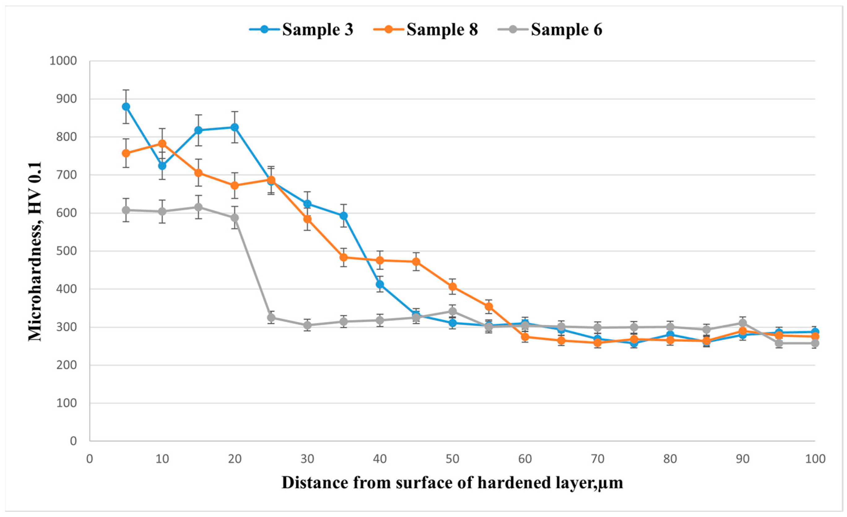
Microhardness profiles (
Figure 8) along the depth (HV0.1) for the three modes show pronounced surface hardening followed by a monotonic decrease to the substrate level (~260–300 HV) at a depth of 70–90 μm. Sample 3 (d = 6 mm, 20 min, 40 Hz) exhibits a maximum surface hardness of ≈880 HV at 5 μm and maintains ≥600 HV up to ~35 μm; the effective depth of the hardened layer (down to ~300 HV) is ≈58–60 μm. Sample 8 (d = 7.5 mm, 20 min, 40 Hz) shows a slightly lower surface hardness of ≈750–780 HV but a comparable layer depth (≈58–60 μm), while maintaining 450–500 HV in the 30–45 μm range. Sample 6 (d = 6 mm, 20 min, 50 Hz) is characterized by the lowest values: surface hardness of ≈600–620 HV and a sharp “break” in the curve at 20–25 μm, dropping to ≈320 HV, resulting in a layer thickness of ~25–30 μm. The obtained hierarchy (3 > 8 > 6 in terms of hardening level and depth) is consistent with the XRD phase analysis: samples 3 and 8 exhibit a more pronounced γN phase (expanded austenite), providing higher hardness and greater hardening depth, whereas sample 6 contains a smaller fraction of γN and forms a thinner layer.
Microhardness profiles (
Figure 8) exhibit an exponential decrease with depth, which can be described by the following expression:
where HV
s is the surface hardness, HV
0 is the substrate hardness, and δ is the effective diffusion depth (~60 µm for sample No. 3). The surface hardness reaches 880 ± 20 HV, which is 3.7 times higher than that of the initial state. The increase in hardness directly correlates with the fraction of the γN phase, confirming that strengthening is caused by lattice expansion and interstitial incorporation of nitrogen.
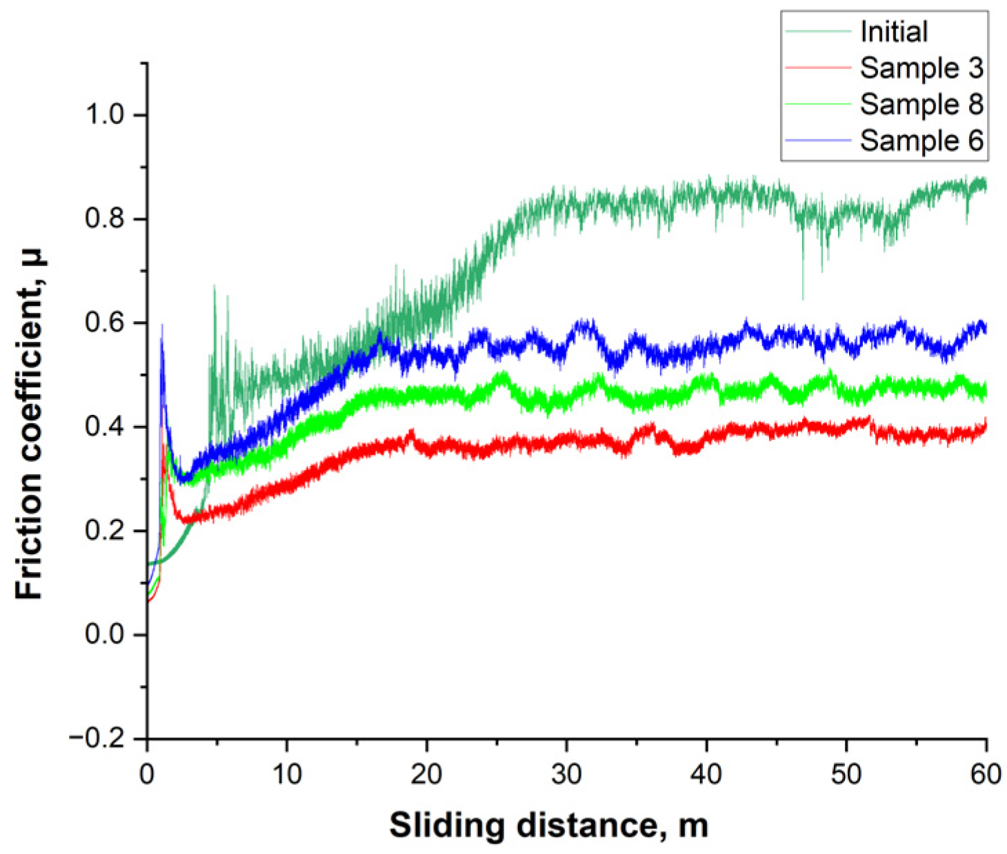
The behavior of the friction coefficient (μ) under dry sliding clearly distinguishes the initial steel from the nitrided samples, as shown in
Figure 9. After a short running-in stage (first ~1–2 m), the initial state exhibits a high and noisy plateau with μ ≈ 0.80–0.90, indicating intense formation and rupture of an oxide-abrasive third body. For sample 6, a lower and more stable level of μ ≈ 0.55–0.60 is established; however, the amplitude of fluctuations remains noticeable, and a tendency for an increase is observed at 40–60 m, which corresponds to the smaller thickness of the hardened layer (~25–30 μm) and the earlier involvement of the substrate in contact. Sample 8 exhibits intermediate behavior with a plateau of μ ≈ 0.45–0.50, stable throughout the entire track length, reflecting a deeper hardened layer (~60 μm) and stable tribofilm formation. The best result is shown by sample 3: after the running-in stage, the lowest plateau of μ ≈ 0.35–0.40 is formed with minimal signal noise, indicating stable performance of the γN surface layer and a low proportion of adhesive/abrasive events. Compared to the initial state, the reduction in friction level is approximately 55% (sample 3), 45% (sample 8), and 35% (sample 6). Overall, this is consistent with the XRD and microhardness results: samples 3 and 8, which have a higher fraction of expanded austenite γN and a thicker layer, provide lower and more stable friction, whereas sample 6, with a thinner modified layer, exhibits higher μ values and greater instability during prolonged sliding.
Figure 10 presents the cross-sectional profilograms of wear tracks obtained after tribological tests of austenitic stainless steel 12Kh18N10T samples in the initial state (a) and after electrolytic-plasma nitriding under different modes of preliminary mechanical treatment: sample 6 (b), sample 8 (c), and sample 3 (d). For the initial steel (
Figure 10a), a wide and deep wear track profile is characteristic, with a wear area of ≈1.76 × 10
4 μm
2 and significant bottom roughness. Such morphology indicates the predominance of an adhesive-abrasive wear mechanism with plastic metal flow along the edges of the groove.
After electrolytic-plasma nitriding, a significant reduction in wear area and smoothing of the profile are observed. For sample 6 (
Figure 10b), the depth of the wear track decreases by almost 1.5 times (S = 2.67 × 10
4 → 1.95 × 10
4 μm
2), which is associated with the formation of a hardened layer 25–30 μm thick. However, the profile shape remains asymmetric, indicating partial destruction of the γN layer in the central contact zone due to insufficient thickness and local involvement of the substrate in friction. For sample 8 (
Figure 10c), the wear depth and area are even smaller (S = 2.19 × 10
4 μm
2), the profile contour is symmetrical, and the track edges show no pronounced bulging. This confirms the stability and uniformity of the tribofilm, which is consistent with the optimal γN layer thickness (~60 μm) and high microhardness (~750–780 HV). The most favorable profile is exhibited by sample 3 (
Figure 10d): minimal wear depth (~10 μm), narrow contact zone (S = 1.95 × 10
4 μm
2), and smooth contours, indicating high wear resistance and stable friction without seizure. This confirms that under moderate preliminary mechanical treatment parameters (d = 6 mm, v = 40 Hz, t = 20 min), an optimal expanded austenite γN layer is formed, providing a combination of high hardness, plasticity, and low friction coefficient (μ ≈ 0.35–0.40). Comparison of the profilograms confirms a direct correlation between wear morphology and the microstructural state of the layer: as the profile depth and track area decrease, the fraction of γN phase increases, CrN decreases, and the stability of the tribosystem improves. Wear profiles showed a decrease in wear track area from 1.76 × 10
4 µm
2 (initial state) to 1.95 × 10
4 µm
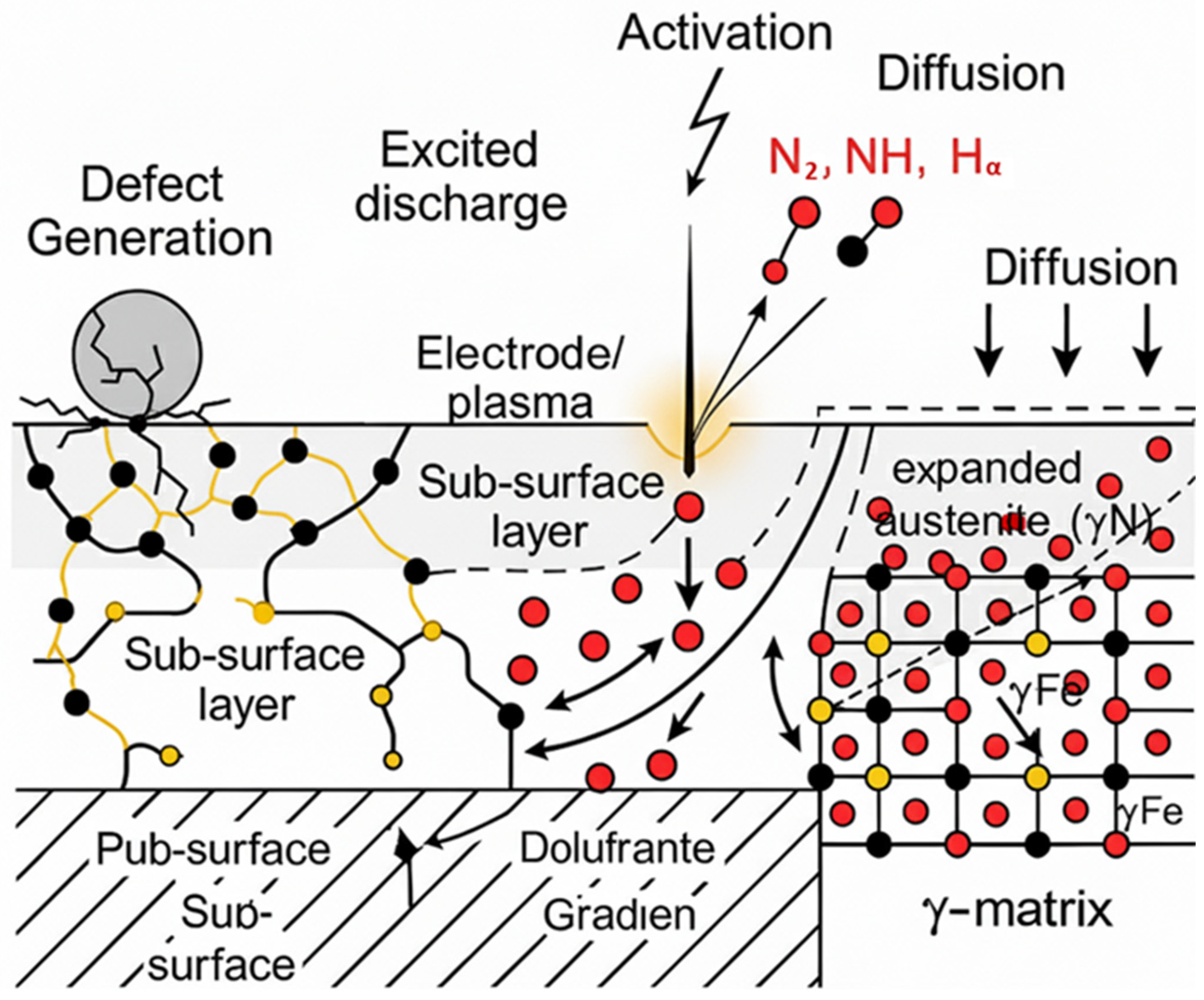
2 (sample No. 3) and a change in the dominant mechanism from adhesive–abrasive to mild oxidative wear, characterized by the formation of a stable tribofilm. The main mechanism of improved wear resistance and reduced friction is defect-assisted diffusion, which ensures stabilization of the γN phase and the formation of a self-lubricating surface layer during friction.
The specific volumetric wear (μ) was calculated using the classical tribological relationship:
where
μ—specific volumetric wear, mm3/(N·m);
V—volume of the worn material, mm3, determined by integrating the wear profile area;
F—applied load, N;
S—total sliding distance, m.
Analysis of the wear track profilograms (
Figure 10) showed that electrolytic-plasma nitriding significantly reduces the depth and area of wear compared to the initial 12Kh18N10T (AISI 321) steel. The greatest reduction in wear parameters is observed for sample No. 3, which underwent preliminary mechanical treatment with optimal intensity (d = 6 mm, v = 40 Hz). This effect is attributed to the formation of a uniform and ductile γN phase possessing increased hardness and resistance to adhesive–abrasive damage. Samples No. 6 and No. 8 show an intermediate reduction in wear, which is associated with partial formation of nitride phases and local reduction in the plasticity of the surface layer under more intense mechanical treatment. The calculation of specific volumetric wear showed a decrease in μ from 1.40 × 10
−3 mm
3/(N·m) for the initial state to 0.92 × 10
−3 mm
3/(N·m) for sample No. 3, corresponding to approximately a 35% reduction in material loss. The obtained results confirm that moderate mechanical activation of the surface prior to EPN is a key factor in enhancing the wear resistance of austenitic steel.
