1. Introduction
Supercontinuum (SC) generation has long been a research hotspot in the field of optics [
1]. The nonlinear dynamics of soliton tunneling offer a novel approach to enhancing SC generation efficiency [
2]. When conditions permit, fundamental solitons near the central wavelength can undergo tunneling effects through a finite region of normal group velocity dispersion induced by stimulated Raman self-shifting, forming stable tunneling solitons. This region is typically sandwiched between two regions of anomalous group velocity dispersion [
3]. This phenomenon shares numerous similarities with quantum tunneling in quantum mechanics; hence, it is termed Soliton Spectrum Tunneling (SST) [
4,
5]. The SST effect is also considered to be a way of soliton-induced dispersive wave generation, because the transmitted solitons are phase-matched with the emitted solitons. In this process, the dispersive wave is generated under the action of nonlinear effects and high-order dispersion, also known as ‘Cherenkov radiation wave’ [
6] or ‘non-soliton radiation wave’ [
7]. These waves will continue to radiate energy outward, which can effectively transfer the energy of solitons to other solitons after tunneling, thereby realizing the conversion between solitons and dispersive waves [
8,
9]. We can utilize its short-term stability and self-dissipation characteristics to achieve temporary propagation and automatic destruction of sensitive information, thereby effectively preventing eavesdropping and interception [
10]. At the same time, the SST effect can be applied to control the generation of SC, as it enables wavelength conversion of optical pulses and optimizes the energy distribution of specific wavelengths by generating high-power spectral components, thereby improving the flatness of SC [
11]. Traditional optical fibers have limitations in higher-order dispersion, whereas photonic crystal fibers (PCFs) break these limitations. Due to its tunable dispersion characteristics and high nonlinearity, PCF has become the ideal medium for generating SC [
12]. In 2011, S.P. Stark and other researchers successfully realized a PCF with three zero-dispersion wavelengths (ZDWs) by changing the geometric structure of the PCF and the shape and position of the air hole [
13]. Compared with the double-zero-dispersion PCF, the triple-zero-dispersion PCF has a more flexible dispersion curve and a longer wavelength interval between the dispersion zeros. The first zero-dispersion wavelength is tuned to the near-infrared region, and the third zero-dispersion wavelength is tuned to the mid-infrared region, which effectively controls the broadening of the supercontinuum in both the short-wavelength and mid-infrared directions [
14]. In the triple-zero-dispersion PCF, due to the simultaneous existence of positive dispersion and negative dispersion slopes, the soliton splitting process can not only generate blue-shifted dispersive waves but also generate redshifted dispersive waves at the same time [
15]. The redshifted dispersive wave can excite the SST effect in the mid-infrared region, thereby increasing the width of the dispersive wave and converting the wavelength. Therefore, the SST effect has a wide range of potential applications, especially in the fields of ultrashort pulse compression, optical sensing technology and multi-channel light source communication.
The Airy beam was first experimentally generated by Siviloglou et al. in 2007. It possesses the characteristics of self-acceleration, self-healing, and non-diffraction [
16]. The Airyprime beam is a beam with new propagation characteristics, which is essentially an extension of the Airy beam [
17]. The Airyprime beam is generated by phase modulation of the incident Gaussian beam using a spatial light modulator [
18]. In recent years, some researchers have found that Airyprime beams are generated by optical transformation [
19]. Specifically, an Airy transformation is performed on the incident beams, which are coherently superimposed from four elegant Hermite-Gaussian modes. Compared with the phase modulation generation method, this method can adjust the intensity, centroid, root mean square width, divergence angle, and propagation factor of the Airyprime beam by changing the width control parameters in the x and y directions, allowing for the flexible selection of the best beam configuration in different application scenarios. The Airyprime beam not only retains the characteristics of the Airy beam but also exhibits an interference enhancement effect [
20]. The interference enhancement effect refers to the spontaneous increase in the intensity of the Airyprime beam when it propagates in free space, exceeding the initial light intensity. This is because the Airyprime beam propagates in free space as a coherent superposition of the Airyprime mode and the Airy correlation mode [
21], which enhances the energy of the interference part. This characteristic can effectively resist the loss of light intensity caused by atmospheric disturbances [
22]. Suppose the Airyprime beam with Cartesian symmetry is extended to a circular Airyprime beam. In that case, it will exhibit stronger self-focusing ability than the traditional circular Airy beam under the same beam parameters, and the focusing intensity will be several times higher [
23]. Due to this advantage, the circular Airyprime beam can achieve stronger capture stiffness in particle capture and manipulation in the field of optical tweezers [
24]. In the case of introducing optical vortices, the self-focusing ability of the circular Airyprime beam changes significantly with changes in the topological charge and the radial position of the singular point [
25,
26]. This property enables the beam to generate various special focusing intensity modes and carry orbital angular momentum by adjusting the topological charge and singularity. The Airyprime beam is mathematically isomorphic to the Airyprime pulse. In an experiment, the frequency component is mapped to the time domain by means of dispersion elements (such as fiber or grating) or a pulse modulator so as to transform the characteristics of a spatial Airy beam into the time form of a pulse. The above research demonstrates that the propagation characteristics and potential applications of Airyprime pulses warrant further study on the dynamics of Airyprime pulse propagation.
Researchers have studied the formation and control of SC in single-ZDW [
27] and double-ZDW [
3] PCFs, as well as the generation of SC in triple-ZDW PCFs with conventional Gaussian pulses [
28]. Zhao et al. found that in the PCF with three zero-dispersion wavelengths, the redshifted dispersive wave will form a channel after entering the normal dispersion region, and the energy will be continuously transferred from the initial soliton to the stable tunneling soliton in the next anomalous dispersion region [
29]. Rong et al. studied the phenomenon of tunable multi-SST in such PCFs using Airy pulses with small truncation coefficients [
3]. Wang Qian et al. discussed the control of SST by symmetric Airy pulses. The results show that the tunneling solitons excited by symmetric Airy pulses not only have higher spectral energy but also can be excited over a shorter propagation distance [
30]. However, existing studies have employed limited Raman shifts, typically only once or a few times at most, resulting in relatively limited means for controlling the energy and spectral width of tunneling solitons. Zhang Lifu et al. demonstrated that Airyprime pulses can generate wide-tunable and robust multicolor solitons under Raman effects [
31]. Therefore, when an Airyprime pulse is incident onto a zero-dispersion photonic crystal fiber exhibiting Raman effects, it is anticipated that the generated multicolor Raman solitons can be converged into a stable tunneling soliton via the tunneling effect. The author further investigated the influence of the initial Airyprime pulse’s truncation coefficient, power, and center position on the tunneling soliton, thereby achieving pulse wavelength conversion. This constitutes a research topic of significant scientific value.
The structure of this paper is as follows:
Section 2 introduces the theoretical analysis, covering the generalized nonlinear Schrödinger equation model, the characteristics of triple-zero-dispersion photonic crystal fibers, and the spectral and propagation properties of Airyprime pulses. It also compares the differences between Airyprime pulses and Airy pulses in generating Raman solitons and tunneling solitons.
Section 3 presents results and discussion, investigating the effects of cutoff coefficient, peak power, and central wavelength on tunneling soliton formation and evolution while revealing propagation characteristics via X-FROG plots.
Section 4 concludes the paper by summarizing key findings and highlighting application prospects in wavelength conversion and supercontinuum control.
3. Results and Discussion
We conducted an in-depth investigation on the temporal and spectral evolution characteristics of Airyprime pulses and Airy pulses in a triple-zero-dispersion medium and performed a comparative analysis of their temporal waveforms and spectral distributions after propagation over 4 m. The results indicate that the Airyprime pulse exhibits significant advantages in generating tunneling solitons. On this basis, we further investigated how adjusting the initial truncation coefficient α, peak power P, and central wavelength λ of the Airyprime pulse can effectively control the energy, pulse width, and central wavelength characteristics of the tunneling solitons generated in the photonic crystal fiber with three zero-dispersion wavelengths.
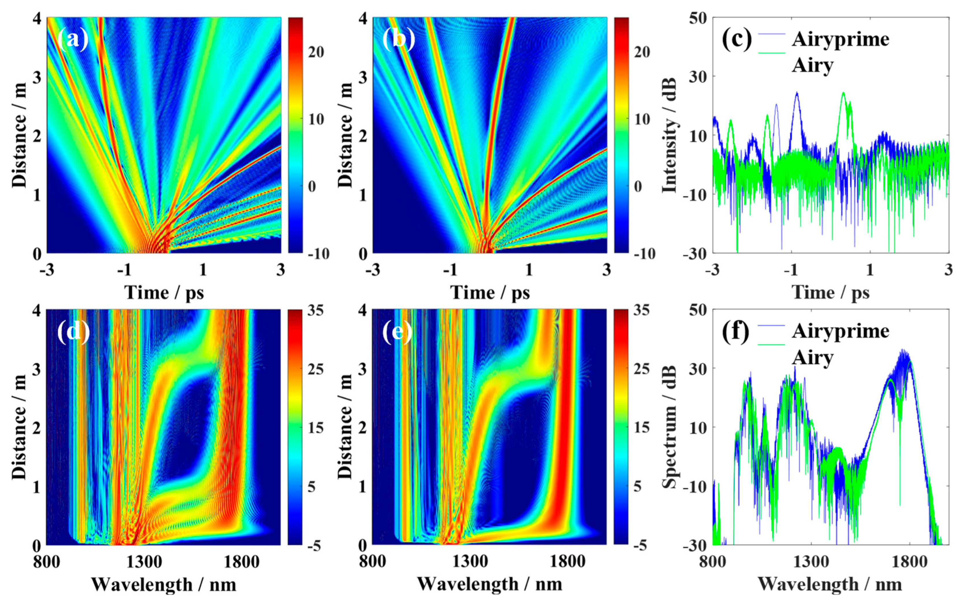
From the time domain evolution diagram, it can be observed that, under the influence of higher-order dispersion and nonlinear effects, the Airyprime pulse first undergoes temporal compression. It then splits into a series of solitons with different group velocities, simultaneously radiating dispersion wave energy outward [
Figure 3a]. Under the effect of Raman self-shift, the split solitons accelerate in a parabolic trajectory, deflecting to the right at a speed proportional to the energy of each peak in the Airyprime pulse. Due to the strong and slowly decaying side lobe energy of the Airyprime pulse, both the central peak and multiple side lobes to its left undergo self-deflection under the Raman effect. In contrast, the Airy pulse exhibits lower side lobe energy, with intensity rapidly decreasing with distance from the central peak, resulting in a significantly smaller number of formed Raman solitons [
Figure 3b,c]. From the frequency domain evolution diagram, it can be observed that the Airyprime pulse undergoes brief temporal compression before splitting into multiple static solitons. New frequency components emerge at shorter wavelengths, representing dispersion waves. Subsequently, the split static solitons undergo stimulated Raman scattering, gradually redshifting and linearly shifting toward longer wavelengths. Concurrently, a portion of energy transfers from the redshifted Raman solitons to shorter wavelengths via phase matching under the influence of higher-order dispersion [
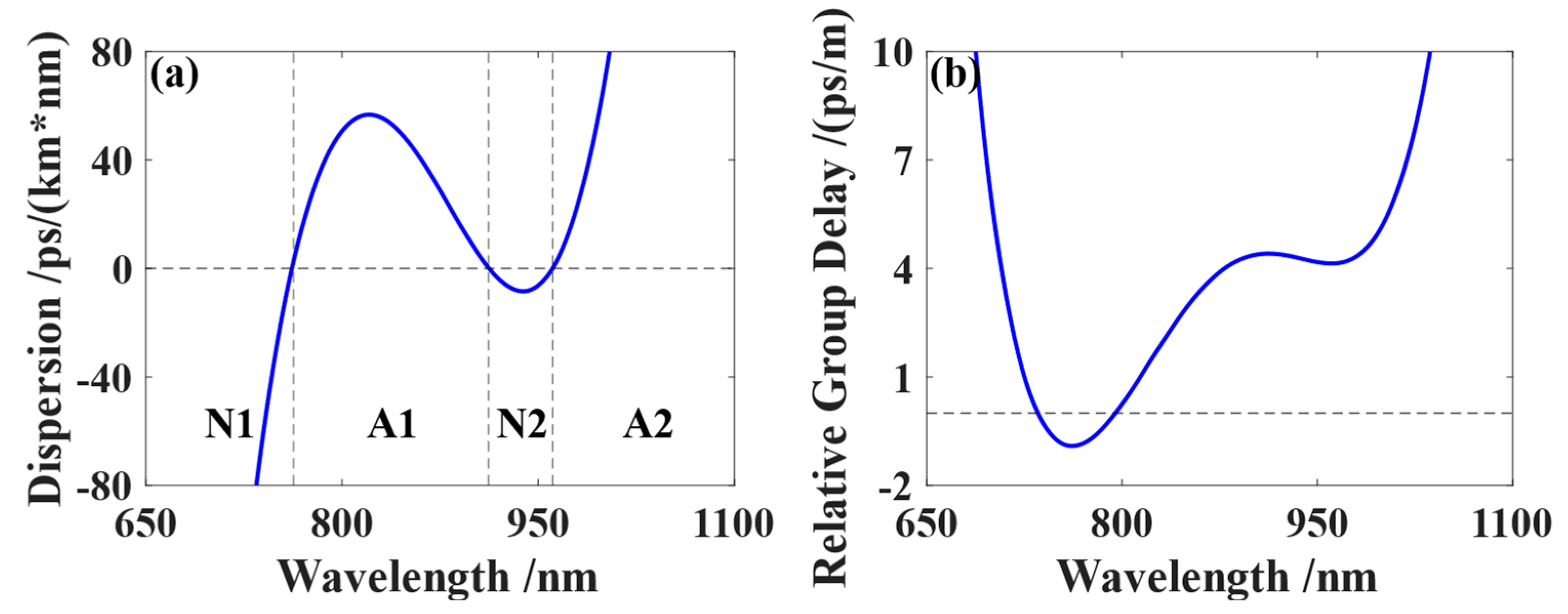
Figure 3d]. The triple-zero-dispersion wavelength PCF features multiple overlapping normal and anomalous GVD regions within its spectrum. Raman solitons in the anomalous GVD region continuously redshift into the normal GVD region, existing as R-DWs. They form a channel within the normal GVD region connecting two adjacent anomalous GVD regions, continuously transferring energy from the initial soliton to stable tunneling solitons within the subsequent anomalous GVD region. The SST effect can be understood as the process of soliton-induced R-DW generation, involving phase matching between the initial soliton and R-DW, as well as between R-DW and the tunneling soliton. The rapid side lobe attenuation of the Airy pulse resulted in only two Raman self-shift events [
Figure 3e]. Since the Airyprime pulse underwent more Raman self-shifts, the resulting tunneling soliton ultimately possessed higher energy [
Figure 3d]. The tunneling soliton formed from the Airy pulse exhibits a collapsed structure due to significant deviation in its central position [
Figure 3f].
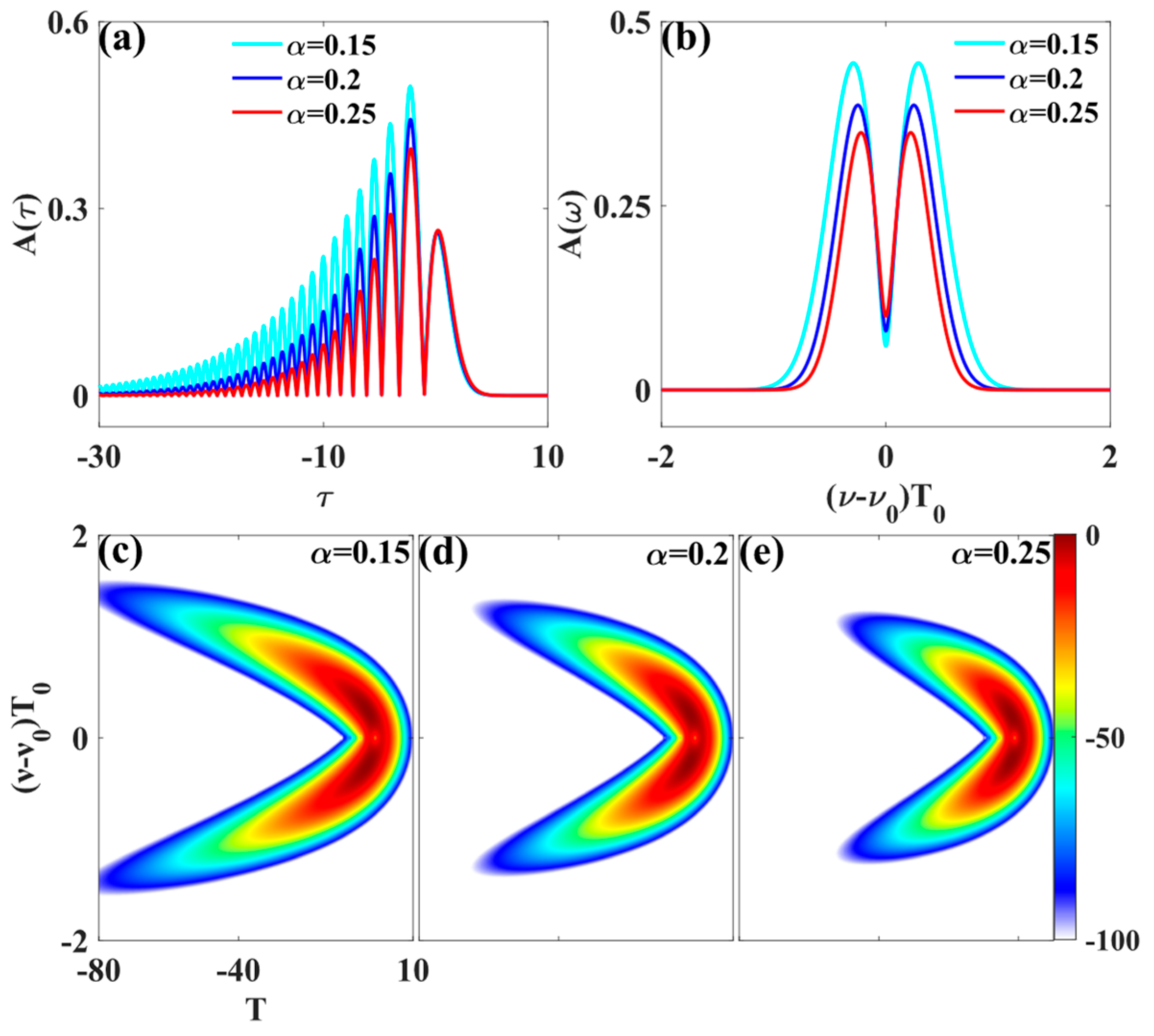
The truncation coefficient
α serves as a tuning parameter for the Airyprime pulse waveform, controlling both pulse width and amplitude. A smaller
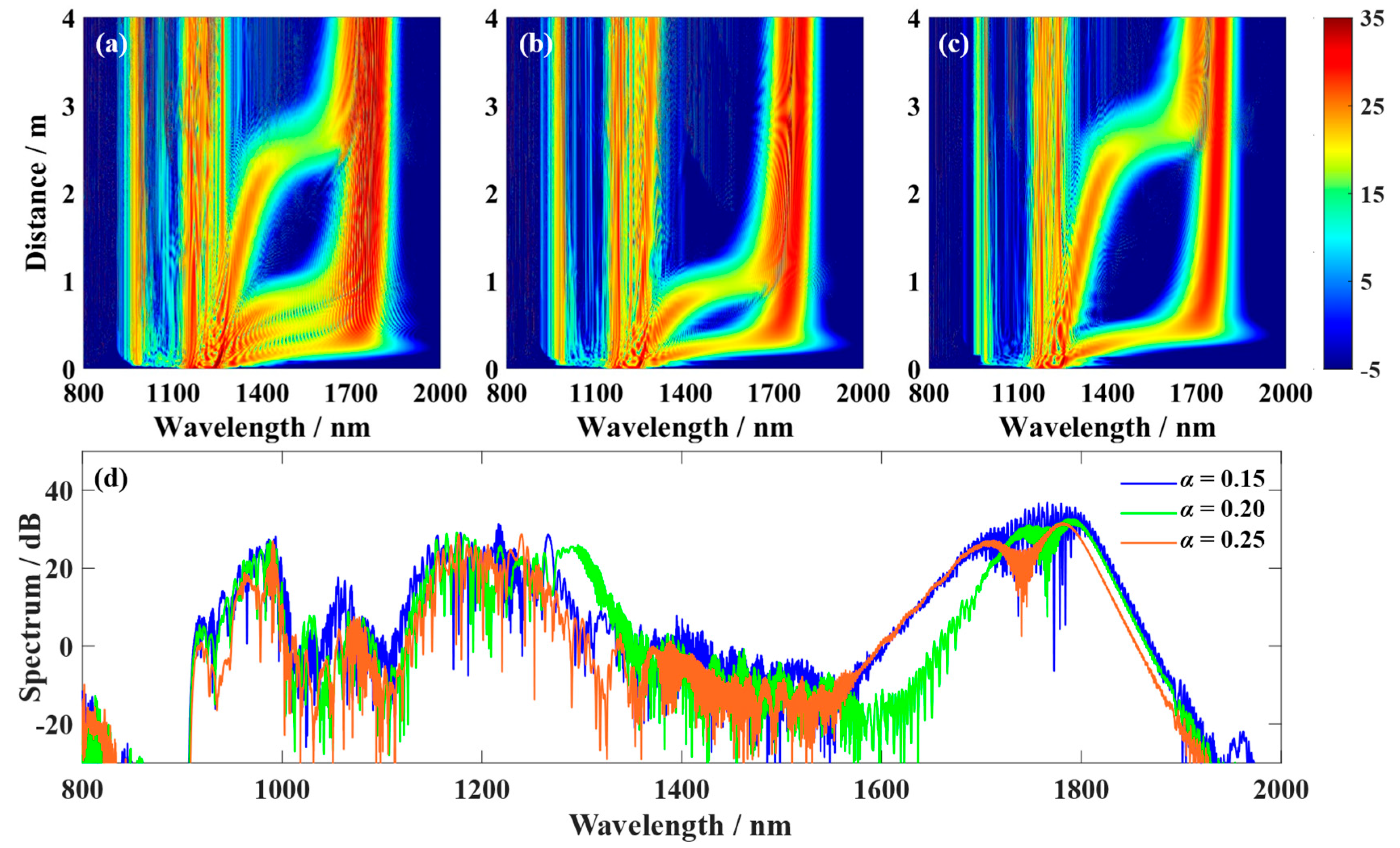
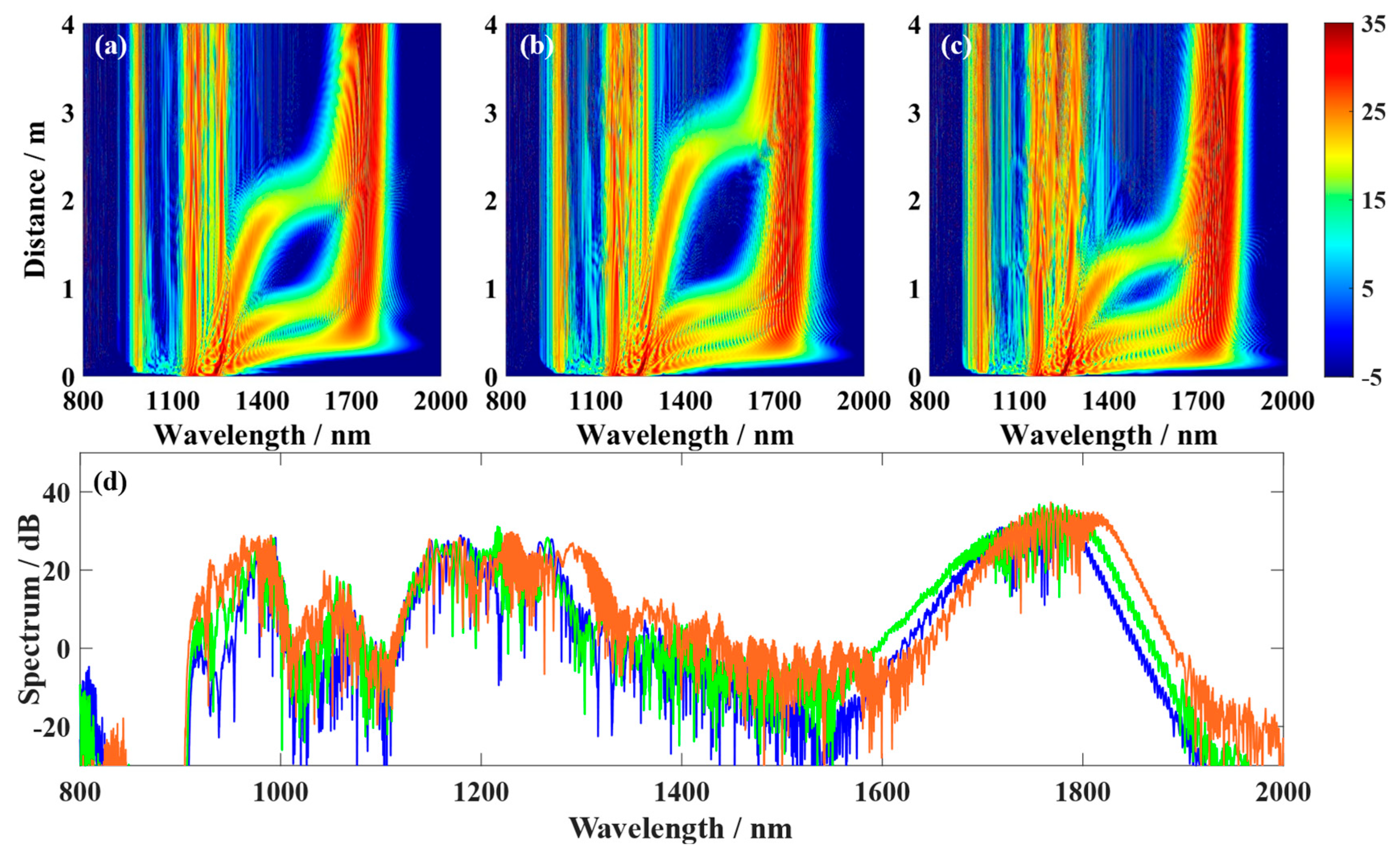
α yields higher peak power and more pronounced Raman effects. Therefore, investigating the influence of the truncation coefficient on Raman effects and spectral tunneling effects is crucial. To this end, numerical simulations were conducted to explore the impact of the truncation coefficient on the generation of spectral tunneling effects in Airyprime pulses. When
α = 0.15, the Airyprime pulse underwent four Raman self-frequencies. The stable propagation tunneling soliton, formed after traversing the quantum channel via tunneling, exhibited the maximum energy [
Figure 4a]. As
α increases, the energy of the central peak and side lobes significantly weakens, the Raman effect diminishes, the number of tunneling events decreases, and the spectral width of the tunneling soliton also narrows [
Figure 4b,c]. When
α = 0.25, the center positions of the generated tunneling solitons exhibit a large gap, resulting in a tunneling soliton spectrum with low flatness and a collapsed structure [
Figure 4c]. These phenomena can be explained as follows: When
α is small, the central peak and right-side lobe of the Airyprime pulse possess substantial energy, promoting Raman self-shifting in the main lobe and part of the side lobes.
The influence of power on Raman self-shift is particularly significant in nonlinear optics. Raman self-shift refers to the phenomenon of linear frequency deviation caused by the Raman effect, where light waves interact with excited states within a medium during propagation, resulting in frequency changes. To investigate the influence of peak power P on the SST effect in Airyprime pulses, numerical simulations were conducted in a triple-zero-dispersion PCF with a cutoff coefficient
α = 0.15 and a center wavelength
λ = 1200 nm. These simulations explored the regulatory role of
P in controlling the tunneling soliton in Airyprime pulses. By combining spectral evolution plots with two-dimensional comparison curves, the dynamic evolution of the SST effect was revealed during the
P value increment from 3000 W to 5000 W. Redshifted solitons detached from the incident pump pulse and exhibited linear deflection due to the Raman scattering effect. In the time domain, this manifested as changes in pulse trajectory, while in the frequency domain, it appeared as spectral redshift. The Raman self-shift effect causes a significant spectral shift toward longer wavelengths, while the short-wavelength spectrum remains nearly unchanged. At
P = 3000 W, the Airyprime pulse generates only three Raman solitons, with closely spaced firm peaks in the main spectrum and a relatively low redshift rate [
Figure 5a]. As
P increases, the Airyprime pulse releases four Raman solitons, with more redshifted peaks separated from the main spectrum [
Figure 5b,c]. At
P = 5000 W, although the number of Raman solitons remains four, their deflection angles significantly increase [
Figure 5c]. The spectrum of the Airyprime pulse at a propagation distance of 4
LD reveals that higher peak power enables stable propagation of Raman solitons tunneling through quantum channels. Although the peak intensity shows little change, the soliton width increases, and its center position undergoes greater redshift [
Figure 5d]. Additionally, the intensity of the blue-shifted dispersive wave (B-DW) exhibits linear growth with increasing power. By adjusting the peak power, the number of Raman self-frequency shifts, the deflection angle, and the energy of the soliton after Raman SST can be effectively controlled.
The central wavelength has an important influence on the generation of SC, especially in the optical fiber process. SC refers to the phenomenon where the spectrum expands to a broader frequency band through the interaction between an intense light pulse and the medium. SC usually depends on the nonlinear propagation characteristics of the pulse, where the central wavelength is a key factor that directly affects the width, intensity distribution, and generation process of SC.
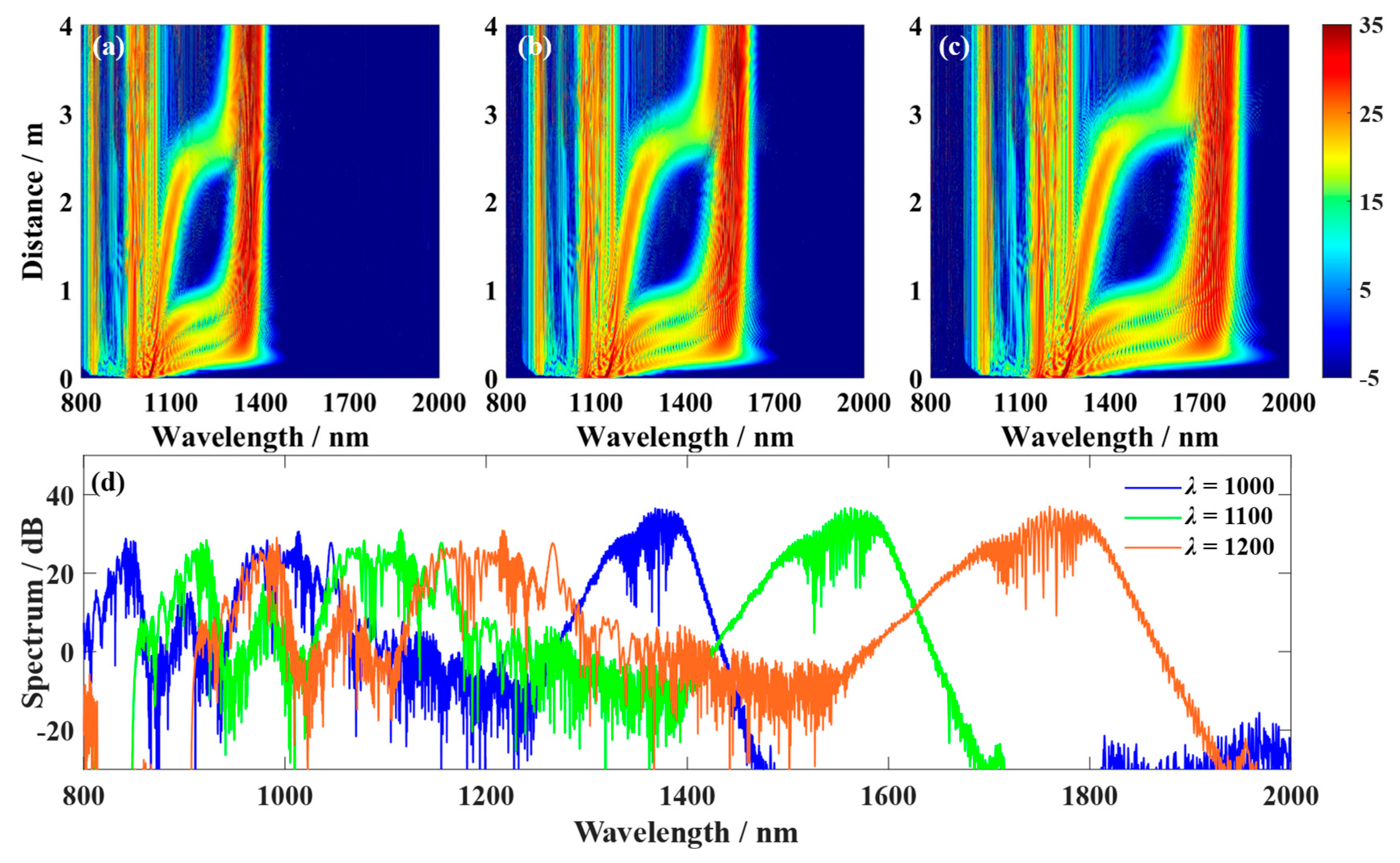
Figure 6 illustrates the generation of tunneling solitons in PCF with zero dispersion at different central wavelengths
λ for Airyprime pulses. At
λ = 1000 nm, the spectrum broadens toward both the short-wavelength (800 nm) and long-wavelength (1300 nm) regions [
Figure 6a]. As the central wavelength increases, although the degree of spectral linear shift due to Raman scattering effects changes little, higher-order soliton generation becomes pronounced [
Figure 6b,c]. This is accompanied by highly efficient redshifted dispersion waves, extending the tunneling soliton spectrum to 1800 nm on the long-wavelength side. Concurrently, the B-DW broadening diminishes to 900 nm. The spectrum of the Airyprime pulse at a propagation distance of 4
LD reveals. At
λ = 1000 nm, the energy enhancement of the tunneling soliton is limited due to the dispersion-induced redshift effect, resulting in the narrowest width. At
λ = 1200 nm, the tunneling intensity increases, leading to a significant expansion in both the width and central wavelength position of the tunneling soliton [
Figure 6d]. By adjusting the central wavelength of the pulse, the formation and evolution of tunneling solitons can be effectively controlled, thereby regulating the broadening range and energy distribution characteristics of the tunneling soliton spectrum.
Figure 7 illustrates the influence of different parameters on the width of tunneling solitons in a zero-dispersion wavelength PCF. It can be observed that as the cutoff coefficient increases, the soliton width first decreases and then increases, exhibiting a distinct U-shaped trend. When the cutoff coefficient approaches approximately 0.2, the width of the tunneling soliton reaches its minimum value [
Figure 7a]. When the cutoff coefficient exceeds 0.2, the continued increase in soliton width stems from significant positional deviation of the soliton center caused by multiple tunneling effects. Although the soliton width increases at this point, its flatness decreases markedly. Additionally, as the power increases, the tunneling soliton width continues to grow, exhibiting an overall trend of near-linear increase. This indicates that higher power leads to broadening of the tunneling soliton [
Figure 7b]. Finally, the tunneling soliton width increases significantly with increasing central wavelength, exhibiting a clear monotonic upward trend. This demonstrates that longer central wavelengths correspond to broader tunneling soliton spectral widths [
Figure 7c]. Overall, the cutoff coefficient, input power, and central wavelength all significantly influence the width of the tunneling soliton: a smaller cutoff coefficient results in a broader soliton with higher flatness; input power is positively correlated with soliton width; and a longer central wavelength leads to a broader soliton.
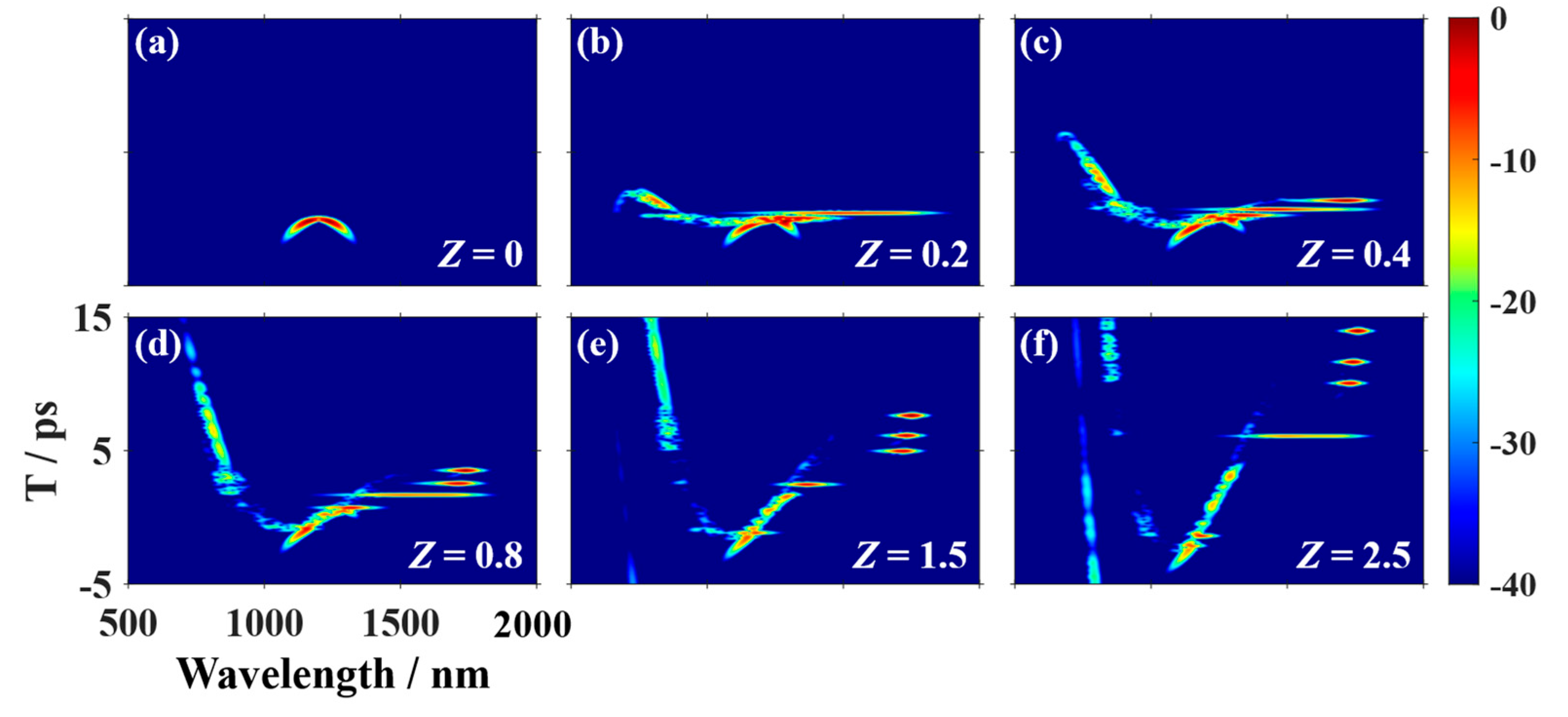
To gain deeper insight into the formation process of the SST effect during pulse propagation,
Figure 7 presents the X-FROG traces of output pulses for six different propagation distances when an Airyprime pulse with parameters
λ = 1200,
P = 4000, and
α = 0.15 propagates in a PCF featuring three zero-dispersion points. It can be seen from
Figure 8a that the Airyprime pulse signal has a highly narrow pulse width in the short-wavelength anomalous GVD region at the input end of the PCF. When the pulse is transmitted to the
Z = 0.2 position, it can be observed that the SPM-dominated spectrum broadening basically ends, and the higher-order solitons have begun to split. Because of the influence of nonlinear effects, the spectrum broadening is asymmetric. When the pulse signal is transmitted to 0.4 m, as shown in
Figure 8c, due to the high-order nonlinear effect and dispersion, the high-order solitons begin to split and emit the first fundamental soliton, accompanied by B-DW and R-DW in N1 and N2, respectively. At this time, the R-DW in N2 forms an energy channel. From
Figure 8d, it can be seen that under the action of SSFS, the fundamental solitons are continuously redshifted, and the number of quantum channels increases. In the process of the soliton self-frequency shift effect, as shown in
Figure 8e, the energy of the initial soliton in A1 is continuously transferred to the tunneling soliton in A2, and the number of quantum channels reaches the maximum. As the propagation distance continues to increase, the number of quantum channels remains unchanged. By reasonably adjusting the propagation distance, we can effectively control the generation time and spectral width of tunneling solitons.
4. Conclusions
In this paper, the generation of multicolor Raman solitons and tunneling solitons based on Airyprime pulses and their propagation characteristics in a triple-zero-dispersion wavelength PCF are studied. By adjusting the parameters of the Airyprime pulse, such as the truncation coefficient, input power, and center wavelength, we can discuss their effects on the SST effect. The results show that the Airyprime pulse has strong nonlinear effects and self-accelerating characteristics. It can generate multiple Raman solitons in the fiber and form stable tunneling solitons through the SST effect. This process is not only closely related to the Raman self-frequency shift but also significantly affected by the dispersion characteristics and nonlinear effects. By adjusting the truncation coefficient of the Airyprime pulse, the energy, width, and central wavelength characteristics of tunneling solitons can be effectively controlled. It is found that the smaller the truncation coefficient, the stronger the Raman effect and the greater the energy of the tunneling soliton; the width also increases. As the truncation coefficient increases, the number of Raman self-frequency shifts decreases, the final tunneling soliton energy is small, and the spectral width is narrow. In addition, the input power and central wavelength also have an essential influence on the characteristics of tunneling solitons. As the power increases, the width of the tunneling soliton significantly increases, and the energy distribution becomes more concentrated. The change in the central wavelength mainly affects the redshift degree and width of the tunneling soliton. The longer central wavelength leads to an increase in the width of the tunneling soliton, causing the spectrum to expand to longer wavelengths. These results provide a theoretical basis for more accurate wavelength conversion by adjusting the initial pulse parameters. It is also shown that in PCFs with multiple ZDWs, the SST effect can effectively realize applications such as ultrashort pulse compression, optical sensing technology, and multi-channel light source communication. Through in-depth analysis of the propagation of Airyprime pulses in PCF, this paper provides new ideas and methods for PCF-based SC generation and wavelength conversion technology. In summary, Airyprime pulses show great potential in Raman soliton generation, tunneling effect, and wavelength control, which will be used in future ultrafast optical devices and optical communication technology. Future research can be carried out in the following directions: Further studies can be conducted on the influence of different PCF structures—such as asymmetric cladding designs or adjustable air-hole arrangements—on the propagation characteristics of Airyprime pulses in order to achieve more precise control over the conditions for tunneling soliton generation. In addition, the effects of other types of abrupt pulses, such as Pearce pulses, swallowtail pulses, and butterfly pulses, on the formation of tunneling solitons can be explored to broaden the understanding of nonlinear pulse dynamics. Finally, future work can combine experimental investigations with numerical simulations to verify the theoretical results and provide stronger support for the proposed model.
