Abstract
Effective detection of acoustic signals plays a crucial role in numerous fields, including industrial equipment fault prediction and environmental monitoring. Acoustic sensing technology, owing to its substantial information carrying capacity and non-contact measurement advantages, has garnered widespread attention in relevant applications. However, the effective detection of weak target acoustic signals amidst strong noise interference remains a critical challenge in this field. The core bottleneck lies in the difficulty of traditional detection methods to simultaneously achieve both high sensitivity and high directionality. To address this limitation, this work proposes a line-defect phononic crystal (PnC) structure that enables directional enhancement and detection of weak target signals under intense spatial noise interference by coupling defect state localization characteristics with anisotropy mechanisms. Through theoretical derivation and finite element numerical simulation, the directional enhancement properties of this structure were systematically validated. Furthermore, numerical simulations were conducted to validate the detection of weak harmonic signals and weak bearing fault signals under strong spatial noise interference. The results demonstrate that this line-defect phononic crystal (PnC) structure exhibits high feasibility and outstanding performance in detecting weak acoustic signals. This work provides novel insights for developing new acoustic detection methods combining high sensitivity with high directivity, showcasing unique advantages and broad application prospects in acoustic signal sensing, enhancement, and localization.
1. Introduction
Acoustic signals are energy signals propagating through media such as gases and liquids, carrying rich physical information. Acoustic directional detection plays a crucial role in numerous fields, with typical applications including microphone design [1,2,3], acoustic communication [4,5,6] and industrial equipment health monitoring [7,8,9]. The core method for traditional acoustic directional detection is microphone array technology, but its detection accuracy is severely constrained by the performance of signal processing algorithms and the physical dimensions of the array [10,11,12]. Additionally, biomimetic microphones inspired by insects in nature offer novel approaches to acoustic directional detection. Examples include bionic directional perception microphones developed by mimicking the sensory characteristics of micro-insects such as Fly Ormia ochracea [13] and Achroia grisella [14]. However, while these technologies have opened new avenues for acoustic directional detection, spatial noise from multiple directions easily overlaps with target acoustic signals in high-noise environments, causing detection accuracy to plummet or even fail. Therefore, developing novel acoustic direction-finding methods to overcome the technical bottleneck of detecting weak acoustic signals holds significant theoretical value and engineering importance.
Over the past two decades, phononic crystals (PnCs) have emerged as artificial structures capable of manipulating acoustic wave propagation, garnering significant academic and engineering interest through their unique physical properties. Consequently, PnCs demonstrate broad application prospects in acoustic wave control, including but not limited to acoustic superlensing [15,16,17], acoustic cloaking [18,19,20], acoustic focusing [21,22,23,24], and acoustic diodes and acoustic noise reduction [25,26,27,28]. These characteristics establish a foundation for revolutionizing directional acoustic detection, enabling novel methodologies with high sensitivity and directivity. For instance, Miniaci et al. [29] proposed a hypersensitive PnC device that demonstrates filtering and spatial focusing functionalities within specific target frequency ranges. When integrated with time reversal techniques, this device allows for the detection and localization of nonlinear elastic sources, including cracks and delaminations. Ma et al. [30] designed a PnC structure with near-zero refractive index, achieving effective detection of weak Gaussian distributed sinusoidal pulse signals submerged within 30° spatial noise. Xiao et al. [31] created a phononic crystal resonator (PnCR) with directional enhancement capability, which successfully detected gear fault signals under 104.4 dB sound pressure level noise interference. PnCs with defect patterns enable the localization and amplification of acoustic energy, demonstrating significant potential in numerous novel applications such as acoustic sensing [32,33], tunable actuation [34,35], and acoustic energy harvesting [36,37]. Recent studies [38,39,40,41] report novel defect-mode PnCs with integrated acoustic enhancement and directional sensing functions through coupled-resonator configurations. However, resonator-coupled designs inevitably increase structural complexity and manufacturing costs. Approaches leveraging intrinsic structural properties of defect-mode PnCs for directional enhancement remain underexplored.
Compared to coupled resonator PnCs, anisotropic PnCs offer the advantages of simpler structural design and lower manufacturing costs [42,43]. Inspired by anisotropic PnCs, this paper proposes a line-defect PnC structure that combines high sensitivity with high directivity. It aims to overcome the bottleneck in detecting weak acoustic signals in strong noise environments by achieving directional enhancement detection. To achieve this goal, a unit cell structure featuring an inner rectangular cavity intersecting with a straight channel is designed. This unit cell is then periodically arranged in two dimensions to construct a line-defect supercell. Through deep analysis of the structural dispersion relations and acoustic transmission properties, the physical mechanism enabling acoustic enhancement and directional sensing in the proposed line-defect PnC is elucidated. Furthermore, numerical simulation results demonstrate that the designed line-defect PnC exhibits superior directional enhancement detection performance for both weak harmonic signals and weak bearing fault signals under strong complex spatial noise interference.
2. Structural Design and Theoretical Calculations
2.1. Structural Design
To achieve directional enhancement of incident acoustic signals, this paper proposes a periodically distributed anisotropic line-defect PnC structure, as shown in Figure 1a. Based on the design principles of anisotropic PnCs [42,43], the unit cell was designed with a penetrating rectangular cavity and straight channels. Meanwhile, in consideration of structural fabrication and application constraints, the key geometric parameters were designed as follows: lattice constant a = 60 mm, inner rectangular cavity length b = 44 mm and straight channel width c = 10 mm, as shown in Figure 1b. The white region corresponds to air, characterized by a mass density of ρair = 1.21 kg/m3 and a sound velocity of cair = 343 m/s. Considering structural practicality and manufacturability, photosensitive resin (blue regions in Figure 1b) was selected with material properties: with the mass density ρ1 = 1050 kg/m3, sound speed c1 = 2540 m/s, Young’s modulus E1 = 5.08 GPa and Poisson’s ratio μ = 0.35, respectively. By periodically arranging structures in the x and y directions, one may obtain an ideal two-dimensional square lattice perfect PnC. Figure 1c illustrates a 4 × 1 perfect supercell. As depicted in Figure 1d, removing the two central columns of the perfect supercell (blue shaded region in Figure 1c) induces a line-defect cavity (orange shaded region in Figure 1d), thereby generating Anderson localization effects for acoustic energy [44].
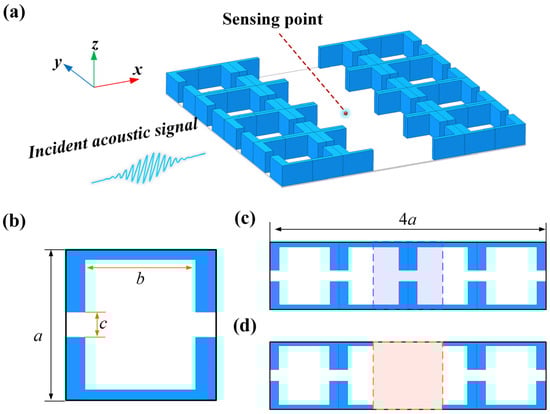
Figure 1.
(a) Three-dimensional view of the proposed directional enhanced line-defect PnC; (b) Unit cell; (c) 4 × 1 supercell of perfect PnC and (d) line-defect PnC. The blue shaded areas indicate sections to be removed, and the orange shaded areas represent line-defect cavities.
2.2. Theoretical Calculation of Dispersion Relations
Dispersion relation analysis serves as a fundamental approach for investigating wave-manipulation characteristics in PnCs. The finite element method (FEM) is commonly employed to investigate acoustic wave propagation in PnCs owing to its computational efficiency, superior convergence, and ability to accommodate arbitrarily complex structures [45,46,47]. In this study, the dispersion relations of the proposed structure were calculated using FEM combined with supercell analysis. The propagation of sound waves in periodic structures is governed by the Helmholtz equation [48]:
where P(r) represents the sound pressure field, r = {x, y} denotes the position vector, and ω stands for the angular frequency. In line with Bloch’s theory, P(r) within a periodic structure can be expressed as:
where k = {kx, ky} denotes the Bloch wave vector within the first irreducible Brillouin zone (IBZ), Φk is the scalar potential, and Gm stands for the reciprocal lattice vector. The scalar potential Φ(r, t) can be used to define this equation, which is expressed as follows [31]:
Assuming the initial harmonic sound pressure is , Equation (3) may be succinctly rewritten [49]:
As a result, the complete band structure of the structure can be obtained by solving the dispersion relation between the wave vector k and angular frequency ω in Equation (4). The finite element analysis software COMSOL Multiphysics 6.2 was utilized to compute the band structures of the perfect PnC supercell and the line-defect PnC supercell within the first IBZ, and these results are illustrated in Figure 2a,b. In the perfect PnC, an initial band gap exists within the frequency range of 1360 Hz to 3360 Hz (grey region in Figure 2a), indicating that sound waves within this range cannot propagate through the PnC structure. Introducing defects alters the original band gap profile, resulting in new band gaps and generating a defect band near 3324 Hz. This physical phenomenon enables the confinement of evanescent waves within the defect core and adjacent regions, achieving acoustic energy localization as depicted in Figure 2c. Typically, when using defect PnC for acoustic signal detection, the sound pressure signal at the center point is primarily measured to obtain the local sound pressure within the defect PnC. In actual experiments, micro-electro-mechanical system (MEMS) acoustic sensing units can be employed for measurement. This unusual physical property can be harnessed to boost the detection of acoustic signals, in turn enhancing the capabilities of sensing and manipulating sound waves.
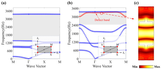
Figure 2.
The band structure of (a) the perfect PnC and (b) the line-defect PnC. (c) Absolute sound pressure distribution of the defective mode propagation solution. The inset shows the first irreducible Brillouin zone, and the red circle indicates the defect band.
2.3. Theoretical Calculation of Directional Enhancement Transmission
To accurately characterize the acoustic transmission properties of the designed line-defect PnC, the acoustic analysis module of COMSOL Multiphysics was used to establish a computational analysis model for the structure, and theoretical numerical calculations were performed on the transmission of the line-defect PnC structure. It should be noted that considering the application scenario of the designed line-defect PnC, where sound waves propagate along the x and y planes (parallel to the structure surface), a Two-dimensional (2D) simulation model was adopted in this study, as illustrated in Figure 3. The 2D model not only enables analysis of the propagation characteristics of the PnC but also significantly reduces computational complexity. This approach has been widely applied in PnC transmission calculations [31,33,39]. In the acoustic transmission calculation model, the incident plane wave propagates from left to right, the amplitude P0 is set to 1 Pa, and the incident angle α is 0°. Given that the material impedance of this structure is significantly higher than that of air, its boundary is defined as a hard acoustic boundary. Additionally, the top and bottom boundaries are configured as rigid boundaries to generate ideal plane waves. Meanwhile, the right boundary is designated as a perfectly matched layer boundary to absorb unwanted acoustic reflections.
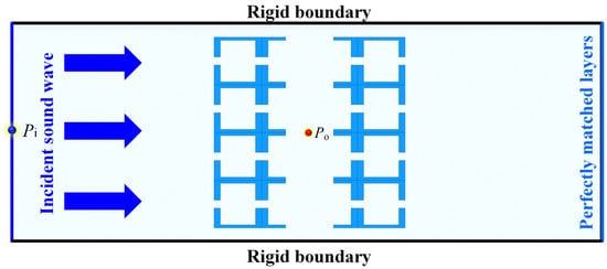
Figure 3.
2D schematic diagram for acoustic transmission analysis of design line-defect PnC.
To calculate the acoustic enhancement effect of the line-defect PnC, the midpoint of the incident boundary is designated as the acoustic incident point Pi, and the midpoint position of the line-defect PnC is set as the measurement point sound pressure Po. Therefore, the local measurement point sound pressure transmission power Tp of the designed line-defect PnC is denoted as [50]:
where incident acoustic power Pin and measured acoustic power Pout can be expressed as:
where pi denotes the sound pressure at the incident point Pi, and po denotes the sound pressure at the measurement point Po, denote the integral at the incident point and measurement point, respectively. S represents the connected acoustic boundary. Furthermore, the sound pressure gain PG of the structure is expressed as:
It should be noted that the designed line-defect PnC structure has narrow channels, and acoustic viscous effects must be taken into account to obtain more accurate numerical solutions for acoustic propagation. We employed the boundary layer impedance method [51,52] to simulate the dissipative effects arising from acoustic viscous forces at all boundaries of the line-defect PnC. To obtain the optimal gain structure, we calculated the sound pressure transmission power spectrum and pressure gain spectrum of the line-defect PnC for different straight channel widths c, with results shown in Figure 4a,b. The results indicate a maximum gain resonance peak near 3324 Hz, corresponding to the band frequency of the structural line defect. It has a transmission power exceeding 24.5 dB and a sound pressure gain exceeding 176.9 times. Therefore, considering the optimal balance between sound pressure gain and structural dimensions, we selected a straight channel width of c = 10 mm.
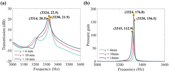
Figure 4.
(a) Pressure transmission power spectrum and (b) Pressure gain spectrum with different straight channel widths c.
To further validate the directional acoustic enhancement capability of the structure, the directional response of the designed line-defect PnC was calculated under varying incident angles α at its resonant frequency of 3324 Hz. Figure 5a presents the absolute sound pressure distributions for three incident angles (α = −25°, 0°, and 45°). It is observed that at α = 0°, the maximum sound pressure is localized at the center of the line-defect PnC. In contrast, waves incident at other angles (e.g., −25° and 45°) exhibit significant attenuation and become undetectable. The normalized sound pressure gain directional response of the structure was calculated and plotted in Figure 5b. The response curve demonstrates a maximum gain at normal incidence (α = 0°) with no observable sidelobe interference. It is worth mentioning that compared to PnCR with equivalent functionality (exceeding 15 dB in transmission power and achieving over 35 times sound pressure gain) [31], the structure designed in this study has a transmission power that is 9 dB higher and a sound pressure gain that is 141 times higher, without the need for complex coupled resonators. This advantage stems from the simplified structural design, which reduces the thermoviscous dissipation of acoustic energy, thereby effectively addressing the high complexity issue commonly faced by high-performance defective PnCs. These theoretical results confirm that the designed line-defect PnC possesses exceptional directional acoustic enhancement properties, establishing it as a high-gain directional acoustic sensing structure.
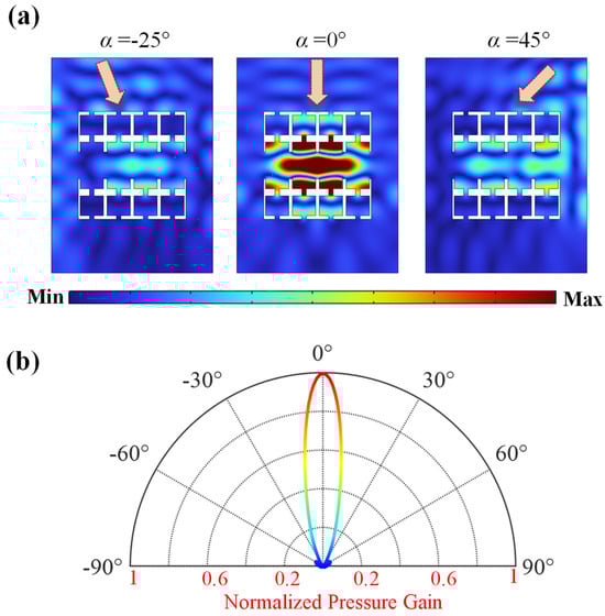
Figure 5.
(a) Absolute sound pressure distribution of the designed line-defect PnC under plane waves at different incident angles. (b) Directional response of normalized pressure gain at resonant frequency 3324 Hz.
3. Analysis of Numerical Simulation Verification Results
3.1. Directional Enhancement Detection of Weak Harmonic Signals
Effectively detecting harmonic signals obscured by spatial noise represents a critical requirement in practical engineering applications. To evaluate the directional enhancement capability of the structure, we constructed a harmonic signal Sh(t) with three distinct incident directions, the specific parameters are shown in Table 1. This was employed to simulate and validate the capability of the structure to detect weak target acoustic signals from the desired direction (α = 0°), which is mathematically expressed as follows:

Table 1.
Detailed parameters of the harmonic signal Sh(t) for numerical simulation detection.
Figure 6a,b show the time-domain and spectrum results of the incident harmonic signal Sh(t) propagating in free space, respectively. Analysis reveals that compared to interference signals from other incident directions, the amplitude of the target sound source at 3324 Hz in the desired direction is extremely weak. However, when detected using the designed line-defect PnC structure, as shown in Figure 6c, the weak harmonic component in the target direction is amplified from an initial 1 Pa to 36 Pa due to the directional enhancement property of this structure. Concurrently, as shown in Figure 6d, interference signals from the other two directions, falling within the structure’s bandgap range, experienced significant suppression of their propagated energy. Their amplitudes decreased from 10 Pa to 8 Pa and 3 Pa, respectively. Additionally, to clarify the distinction between this anisotropic property and the bandgap characteristic, this study constructed a signal Sg(t) with the same frequency as Sh(t) but with an incident angle of 0°. This signal was then detected by the line-defect PnC, with the results shown in Figure 6e,f. Comparing Figure 6d,f reveals that for signals with different frequencies but identical propagation directions, the designed line-defect PnC suppresses interference signals through anisotropic directional suppression. Conversely, for signals with both differing frequencies and propagation directions, interference signals are similarly suppressed via anisotropic directional suppression. This distinction not only results in different amplitude characteristics for interference signals but also leads to noticeable differences in their gain performance relative to the target signal. These results demonstrate that even when the target directional sound source is interfered with by signals from other directions, the designed line-defect PnC can effectively detect and recover the weak sound source from the desired direction while simultaneously suppressing irrelevant noise from other directions.
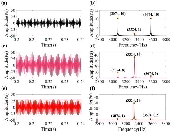
Figure 6.
(a) Time domain waveform and (b) frequency spectrum of the simulation harmonic signal Sh(t) propagating in the free field. (c) Time domain waveform and (d) frequency spectrum of the simulation harmonic signal Sh(t) propagating in the line-defect PnC. (e) Time domain waveform and (f) frequency spectrum of the simulation harmonic signal Sg(t) propagating in the line-defect PnC.
3.2. Directional Enhancement Detection of Weak Bearing Fault Signals
Bearings are the most critical fundamental components in rotating machinery, with their operational status directly impacting the reliable functioning of entire mechanical equipment and industrial production systems. When localized bearing failures occur (such as pitting, cracks, or spalling), rolling elements passing through the damaged area collide with it, generating impacts that excite the bearing’s natural vibrations and subsequently trigger structural resonance. Consequently, bearing fault signals manifest as amplitude-modulated (AM) signals centered on the carrier frequency with the modulation frequency forming the sidebands. These signals can be approximated as the product of an exponentially decaying function and a sine function [53]:
where fr is the rotating frequency, fn is the natural frequency of the bearing, fd is the bearing fault frequency, t = mod (t, 0.99/fn), and ζ is the damping coefficient. Based on this equation, further simulations were conducted to detect bearing fault signals, verifying the potential of the proposed line-defect PnC in industrial inspection applications. Table 2 lists the parameters of the simulated bearing fault signal Sb(t). Additionally, a strong noise source (maximum amplitude of 6 Pa, uniformly distributed broadband white noise) was positioned at approximately 40° azimuth in the horizontal direction to simulate spatial noise interference on the bearing fault signal, as illustrated in Figure 7a.
Table 2.
Detailed parameters of bearing fault signal Sb(t) for numerical simulation detection.

Figure 7.
(a) Schematic of the propagation of bearing fault signals disturbed by spatial noise in 40° direction. (b) Time domain waveform, (c) frequency spectrum and (d) envelope spectrum diagram of the simulated bearing signal Sb(t). (e) Time domain waveform, (f) frequency spectrum and (g) envelope spectrum diagram of the detected bearing signal Sb(t) in the free field.
Figure 7b–d displays the time domain diagram, spectrum diagram and envelope spectrum diagram of the simulated bearing signal Sb(t). The bearing fault signal exhibits periodic impacts in the time domain, with its spectrum exhibiting a harmonic cluster centered on the natural frequency fn. The envelope spectrum obtained via Hilbert transform clearly reveals the characteristic fault frequency fd and its harmonics. Figure 7e–g presents the time domain waveform, spectrum, and envelope spectrum obtained from simulated detection in a free field. Unfortunately, strong noise obscures the bearing fault impact characteristics, rendering the fault sideband signals in the spectrum weak and indistinct. Consequently, the envelope spectrum fails to identify the bearing fault characteristic frequency fd, resulting in unsuccessful bearing fault detection.
The designed line-defect PnC exhibits outstanding acoustic directional enhancement properties, offering significant advantages for detecting weak bearing fault signals. Figure 8a shows the absolute sound pressure distribution of bearing fault signals under spatial noise interference in the free field. It is evident that no valid information can be captured in the free field under strong noise interference. Figure 8b the corresponding sound pressure distribution of a weak bearing fault signal at the line-defect PnC under spatial noise interference. It is observed that the fault signal energy is concentrated at the center of the line-defect PnC detection point. Surprisingly, the line-defect PnC significantly suppresses noise interference, fully preserving the bearing’s fault impact characteristics and faint fault features while markedly amplifying the fault signatures, as shown in Figure 8d,e. Furthermore, comparing Figure 7d and Figure 8e reveals that the envelope spectrum of the online defect PnC detection not only successfully identifies the fault characteristic frequency fd and its harmonics but also exhibits amplitudes far exceeding those of the characteristic frequencies in the bearing fault signal itself. All findings confirm that the proposed line-defect PnC enables directional enhancement of weak sound sources in the target direction amid strong spatial noise interference, while retaining excellent directional gain. This structure thereby demonstrates significant potential for detecting faint acoustic signals.
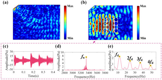
Figure 8.
Absolute sound pressure distribution of bearing fault signals under directional noise interference in (a) the free field and (b) the designed line-defect PnC. (c) Time domain waveform, (d) frequency spectrum and (e) envelope spectrum diagram of the detected bearing signal Sb(t) in the line-defect PnC.
4. Conclusions
To address the technical bottleneck of directional detection of weak acoustic signals in environments with strong spatial noise, this paper proposes a line-defect PnC structure that couples defect-state localization characteristics with structural anisotropy mechanisms. This structure achieves directional enhancement and detection of weak acoustic signals from the target direction. Through theoretical derivation and numerical simulation experiments, the directional enhancement characteristics of the designed structure were systematically evaluated and verified. The main conclusions are as follows:
- (1)
- The proposed PnC exhibits exceptional transmission gain for target signals, theoretically achieving over 24.5 dB acoustic power transmission gain and 176.9 times sound pressure enhancement.
- (2)
- Benefiting from the anisotropic design of the structure, this line-defect PnC achieves outstanding azimuthal resolution without relying on complex coupling structures. It demonstrates high sensitivity and directional sensitivity for target acoustic signals, particularly at points of interest such as 0°. Simultaneously, its straightforward structural design and manufacturing process significantly reduce costs in industrial applications, showcasing remarkable economic advantages.
- (3)
- Compared to conventional acoustic detection techniques, the method based on this line-defect PnC enables directional enhancement and detection of weak acoustic signals without requiring complex array sensor structures or post-processing algorithms. It effectively detects weak harmonic signals and weak bearing fault signals amidst strong spatial noise interference.
In summary, this approach provides novel insights and theoretical guidance for developing high-sensitivity and high-directivity acoustic detection technologies, demonstrating significant application potential in the perception, enhancement, and localization of weak acoustic signals.
Author Contributions
Conceptualization, S.Z. and J.X.; methodology, J.X.; software, S.Z. and J.X.; validation, J.M.; formal analysis, J.X.; investigation, J.M.; resources, J.X.; data curation, J.M.; writing—original draft preparation, S.Z.; writing—review and editing, S.Z. and J.X.; visualization, H.X.; supervision, H.X.; project administration, H.X.; funding acquisition, S.Z. and H.X. All authors have read and agreed to the published version of the manuscript.
Funding
This research was funded by the Key R&D Program of Henan Province, grant number 231111241300, and the Key Scientific Research projects in higher education institutions of Henan Province, grant number 24A460020.
Data Availability Statement
The original contributions presented in this study are included in the article. Further inquiries can be directed to the corresponding author(s).
Acknowledgments
The author sincerely expresses gratitude to all co-authors for their invaluable theoretical contributions and steadfast support throughout this research.
Conflicts of Interest
Huiqiang Xu was employed by China Xuchang Xuji Wind Power Technology Co., Ltd. The remaining authors declare that the research was conducted in the absence of any commercial or financial relationships that could be construed as a potential conflict of interest. The funders had role in the writing of the manuscript and in the decision to publish the results.
References
- Ivancic, J.; Alves, F. Directional Multi-Resonant Micro-Electromechanical System Acoustic Sensor for Low Frequency Detection. Sensors 2024, 24, 2908. [Google Scholar] [CrossRef]
- Spachos, P.; Gregori, S.; Deen, M.J. Voice Activated IoT Devices for Healthcare: Design Challenges and Emerging Applications. IEEE Trans. Circuits Syst. II-Express Briefs 2022, 69, 3101–3107. [Google Scholar] [CrossRef]
- Zhang, Z.; Wu, M.; Yin, L.; Gong, C.; Wang, J.; Zhou, S.; Yang, J. Robust feedback controller combined with the remote microphone method for broadband active noise control in headrest. Appl. Acoust. 2022, 195, 108815. [Google Scholar] [CrossRef]
- Mohammadgholiha, M.; Zonzini, F.; Moll, J.; De Marchi, L. Directional Multifrequency Guided Waves Communications Using Discrete Frequency-Steerable Acoustic Transducers. IEEE Trans. Ultrason. Ferroelectr. Freq. Control 2023, 70, 1494–1505. [Google Scholar] [CrossRef]
- Diamant, R.; Lampe, L. Low Probability of Detection for Underwater Acoustic Communication: A Review. IEEE Access 2018, 6, 19099–19112. [Google Scholar] [CrossRef]
- Zhang, M.; Li, M.; Xu, W.; Zhang, F.; Yao, D.; Wang, X.; Dong, W. Soft Wireless Passive Chipless Sensors for Biological Applications: A Review. Biosensors 2025, 15, 6. [Google Scholar] [CrossRef]
- He, Y.; Li, M.; Meng, Z.; Chen, S.; Huang, S.; Hu, Y.; Zou, X. An overview of acoustic emission inspection and monitoring technology in the key components of renewable energy systems. Mech. Syst. Signal Proc. 2021, 148, 107146. [Google Scholar] [CrossRef]
- Ding, X.; Li, Y.; Xiao, J.; He, Q.; Yang, X.; Shao, Y. Parametric Doppler correction analysis for wayside acoustic bearing fault diagnosis. Mech. Syst. Signal Proc. 2022, 166, 108375. [Google Scholar] [CrossRef]
- Zhang, S.; He, Q.; Ouyang, K.; Xiong, W. Multi-bearing weak defect detection for wayside acoustic diagnosis based on a time-varying spatial filtering rearrangement. Mech. Syst. Signal Proc. 2018, 100, 224–241. [Google Scholar] [CrossRef]
- Tang, L.; Tian, H.; Huang, H.; Shi, S.; Ji, Q. A survey of mechanical fault diagnosis based on audio signal analysis. Measurement 2023, 220, 113294. [Google Scholar] [CrossRef]
- Li, Z.; Yin, J.; Wei, Y. Study on fault diagnosis of gear fracture based on beamformer. Appl. Acoust. 2022, 199, 108994. [Google Scholar] [CrossRef]
- Huang, S.; Li, J.; Wu, L.; Zhang, W. Research on acoustic fault diagnosis of bearings based on spatial filtering and time-frequency domain filtering. Measurement 2023, 221, 113533. [Google Scholar] [CrossRef]
- Rahaman, A.; Kim, B. An mm-sized biomimetic directional microphone array for sound source localization in three dimensions. Microsyst. Nanoeng. 2022, 8, 66. [Google Scholar] [CrossRef]
- Diaz-Garcia, L.; Reid, A.; Jackson-Camargo, J.C.; Windmill, J.F.C. Toward a Bio-Inspired Acoustic Sensor: Achroia grisella’s Ear. IEEE Sens. J. 2022, 22, 17746–17753. [Google Scholar] [CrossRef]
- Kaina, N.; Lemoult, F.; Fink, M.; Lerosey, G. Negative refractive index and acoustic superlens from multiple scattering in single negative metamaterials. Nature 2015, 525, 77–81. [Google Scholar] [CrossRef]
- Robillard, J.F.; Bucay, J.; Deymier, P.A.; Shelke, A.; Muralidharan, K.; Merheb, B.; Vasseur, J.O.; Sukhovich, A.; Page, J.H. Resolution limit of a phononic crystal superlens. Phys. Rev. B 2011, 83, 224301. [Google Scholar] [CrossRef]
- Yang, X.; Yin, J.; Yu, G.; Peng, L.; Wang, N. Acoustic superlens using Helmholtz-resonator-based metamaterials. Appl. Phys. Lett. 2015, 107, 5. [Google Scholar] [CrossRef]
- Romero-García, V.; Lamothe, N.; Theocharis, G.; Richoux, O.; García-Raffi, L.M. Stealth Acoustic Materials. Phys. Rev. Appl. 2019, 11, 054076. [Google Scholar] [CrossRef]
- Zhan, J.; Mei, Y.; Li, K.; Zhou, Y.; Chen, J.; Ma, Y. Conformal metamaterial coats for underwater magnetic-acoustic bi-invisibility. Appl. Phys. Lett. 2022, 120, 094104. [Google Scholar] [CrossRef]
- Lian, M.; Duan, L.; Chen, J.; Jia, J.; Su, Y.; Cao, T. Acoustic transmissive cloaking with adjustable capacity to the incident direction. Microsyst. Nanoeng. 2022, 8, 108. [Google Scholar] [CrossRef] [PubMed]
- Ma, F.; Huang, Z.; Liu, C.; Wu, J.H. Acoustic focusing and imaging via phononic crystal and acoustic metamaterials. J. Appl. Phys. 2022, 131, 11103. [Google Scholar] [CrossRef]
- Zhang, F.; Tao, W.; Wang, S.; Hu, Q.; Flowers, G.T.; Gaidai, O. Novel phononic-crystal-arrayed acoustic metalens for long beam focusing in multi-band. Appl. Phys. Express 2023, 16, 75503. [Google Scholar] [CrossRef]
- Park, J.; Lee, G.; Lee, D.; Kim, M.; Rho, J. Double-Focusing Gradient-Index Lens with Elastic Bragg Mirror for Highly Efficient Energy Harvesting. Nanomaterials 2022, 12, 1019. [Google Scholar] [CrossRef]
- Lee, S.; Choi, W.; Park, J.W.; Kim, D.; Nahm, S.; Jeon, W.; Gu, G.X.; Kim, M.; Ryu, S. Machine learning-enabled development of high performance gradient-index phononic crystals for energy focusing and harvesting. Nano Energy 2022, 103, 107846. [Google Scholar] [CrossRef]
- Xiao, J.; Ding, X.; Pan, H.; Zhang, Y.; He, Q.; Shao, Y. Dual-band filtering and enhanced directional via tunable acoustic metamaterial antennas. Smart Mater. Struct. 2024, 33, 55015. [Google Scholar] [CrossRef]
- Zhang, W.; Xin, F. Coiled-up structure with porous material lining for enhanced sound absorption. Int. J. Mech. Sci. 2023, 256, 108480. [Google Scholar] [CrossRef]
- Zhu, X.; Lau, S.; Lu, Z.; Jeon, W. Broadband low-frequency sound absorption by periodic metamaterial resonators embedded in a porous layer. J. Sound Vib. 2019, 461, 114922. [Google Scholar] [CrossRef]
- Bai, Y.; Chen, Y.; Zheng, J. Design of phononic crystal for enhancing low-frequency sound absorption in mufflers. Sci. Rep. 2024, 14, 28921. [Google Scholar] [CrossRef]
- Miniaci, M.; Gliozzi, A.S.; Morvan, B.; Krushynska, A.; Bosia, F.; Scalerandi, M.; Pugno, N.M. Proof of Concept for an Ultrasensitive Technique to Detect and Localize Sources of Elastic Nonlinearity Using Phononic Crystals. Phys. Rev. Lett. 2017, 118, 214301. [Google Scholar] [CrossRef]
- Ma, C.; Gao, S.; Cheng, Y.; Liu, X. Acoustic metamaterial antennas for combined highly directive-sensitive detection. Appl. Phys. Lett. 2019, 115, 053501. [Google Scholar] [CrossRef]
- Xiao, J.; Ding, X.; Wang, Y.; Huang, W.; He, Q.; Shao, Y. Gear fault detection via directional enhancement of phononic crystal resonators. Int. J. Mech. Sci. 2024, 278, 109453. [Google Scholar] [CrossRef]
- Zhang, S.; Hao, G.; Zhao, X.; Liu, Y.; Han, J. Broadband acoustic signal enhancement via gradient metamaterials coupled to crystals. Front. Phys. 2023, 11, 1240468. [Google Scholar] [CrossRef]
- Xiao, J.; Ding, X.; Huang, W.; He, Q.; Shao, Y. Rotating machinery weak fault features enhancement via line-defect phononic crystal sensing. Mech. Syst. Signal Proc. 2024, 220, 111657. [Google Scholar] [CrossRef]
- Yi, C.; Liu, X.; Xiao, C.; Liu, J.; Chen, N. Soft Phononic Crystal with Tunable Bandgap Through Pneumatic Actuation. Adv. Eng. Mater. 2024, 26, 2401913. [Google Scholar] [CrossRef]
- Jo, S. Temperature-Controlled Defective Phononic Crystals with Shape Memory Alloys for Tunable Ultrasonic Sensors. Crystals 2025, 15, 412. [Google Scholar] [CrossRef]
- He, Z.; Zhang, G.; Chen, X.; Cong, Y.; Gu, S.; Hong, J. Elastic wave harvesting in piezoelectric-defect-introduced phononic crystal microplates. Int. J. Mech. Sci. 2023, 239, 107892. [Google Scholar] [CrossRef]
- Wang, K.; Li, X.; Cao, L.; Guo, P.; Fan, G.; Qin, J.; Ma, T. Enhancement of piezoelectric energy harvesting for flexural waves by a metasurface-assisted phononic cavity. Results Phys. 2024, 63, 107870. [Google Scholar] [CrossRef]
- Jiang, T.; He, Q.; Peng, Z. Enhanced directional acoustic sensing with phononic crystal cavity resonance. Appl. Phys. Lett. 2018, 112, 261902. [Google Scholar] [CrossRef]
- Chen, T.; Jiao, J.; Yu, D. Strongly coupled phononic crystals resonator with high energy density for acoustic enhancement and directional sensing. J. Sound Vib. 2022, 529, 116911. [Google Scholar] [CrossRef]
- Zhao, X.; Hao, G.; Shang, Y.; Han, J. Three-Dimensional Gradient Metamaterial Devices Coupled with Phononic Crystals for Acoustic Enhancement Sensing. Crystals 2023, 13, 1191. [Google Scholar] [CrossRef]
- Han, J.; Hao, G.; Yang, W.; Zhao, X. Phononic Crystal Coupled Mie Structure for Acoustic Amplification. Crystals 2023, 13, 1196. [Google Scholar] [CrossRef]
- Lei, Y.; Wu, J.H.; Huang, Z.; Wang, L.; Huang, Y. Broadband directional resonant tunneling emission enhancement via acoustic anisotropic metamaterials. Appl. Acoust. 2022, 200, 109050. [Google Scholar] [CrossRef]
- Qian, J.; Sun, H.; Yuan, S.; Liu, X. Enhanced directional acoustic emission based on anisotropic metamaterials. Appl. Phys. Lett. 2019, 114, 013506. [Google Scholar] [CrossRef]
- Jo, S.; Yoon, H.; Shin, Y.C.; Choi, W.; Park, C.; Kim, M.; Youn, B.D. Designing a phononic crystal with a defect for energy localization and harvesting: Supercell size and defect location. Int. J. Mech. Sci. 2020, 179, 105670. [Google Scholar] [CrossRef]
- Wang, X.; Sun, H.; Chen, T.; Wang, X. Enhanced acoustic localization in the two-dimensional phononic crystals with slit tube defect. Phys. Lett. A 2019, 383, 125918. [Google Scholar] [CrossRef]
- Ma, X.; Li, Z.; Xiang, J.; Wang, C. Optimization of a ring-like phononic crystal structure with bonding layers for band gap. Mech. Syst. Signal Proc. 2022, 173, 109059. [Google Scholar] [CrossRef]
- Li, Y.; Gao, Z.; Cai, K.; Luo, Y. Design of multi-state tunable phononic crystals based on the reconstruction mechanism of guide-rail lattice. Int. J. Mech. Sci. 2023, 254, 108442. [Google Scholar] [CrossRef]
- Jiang, Z.; Zhou, Y.; Zheng, S.; Liu, J.; Xia, B. Waveguides induced by replacing defects in phononic crystal. Int. J. Mech. Sci. 2023, 255, 108464. [Google Scholar] [CrossRef]
- Huang, H.; Huo, S.; Chen, J. Subwavelength elastic topological negative refraction in ternary locally resonant phononic crystals. Int. J. Mech. Sci. 2021, 198, 106391. [Google Scholar] [CrossRef]
- Chen, T.; Wu, B.; Yu, D. Acoustic fault signal extraction via the line-defect phononic crystals. Front. Mech. Eng. 2022, 17, 10. [Google Scholar] [CrossRef]
- Berggren, M.; Bernland, A.; Noreland, D. Acoustic boundary layers as boundary conditions. J. Comput. Phys. 2018, 371, 633–650. [Google Scholar] [CrossRef]
- Thibault, A.; Chabassier, J.; Boutin, H.; Hélie, T. Transmission line coefficients for viscothermal acoustics in conical tubes. J. Sound Vib. 2023, 543, 117355. [Google Scholar] [CrossRef]
- Feng, Z.; Liang, M.; Zhang, Y.; Hou, S. Fault diagnosis for wind turbine planetary gearboxes via demodulation analysis based on ensemble empirical mode decomposition and energy separation. Renew. Energy 2012, 47, 112–126. [Google Scholar] [CrossRef]
Disclaimer/Publisher’s Note: The statements, opinions and data contained in all publications are solely those of the individual author(s) and contributor(s) and not of MDPI and/or the editor(s). MDPI and/or the editor(s) disclaim responsibility for any injury to people or property resulting from any ideas, methods, instructions or products referred to in the content. |
© 2025 by the authors. Licensee MDPI, Basel, Switzerland. This article is an open access article distributed under the terms and conditions of the Creative Commons Attribution (CC BY) license (https://creativecommons.org/licenses/by/4.0/).