Article

Ligament-Size Effects on the Mechanical Behavior of Au/Cu Dual-Phase Spinodoid Nanocubes

1
School of Science, Xi’an University of Architecture and Technology, Xi’an 710055, China
2
School of Materials Engineering, Jiangsu University of Technology, Changzhou 213001, China
*
Author to whom correspondence should be addressed.
Crystals 2025, 15(11), 957; https://doi.org/10.3390/cryst15110957
Submission received: 28 September 2025 / Revised: 1 November 2025 / Accepted: 3 November 2025 / Published: 5 November 2025
(This article belongs to the Section Inorganic Crystalline Materials)

Abstract

Spinodoid nanocubes, inspired by spinodal decomposition, feature bicontinuous dual-phase architectures with high interfacial area, offering a promising platform for tuning nanoscale mechanics. In the present study, classical molecular dynamics simulations are carried out to investigate the mechanical properties and deformation behaviors of Au/Cu dual-phase spinodoid nanocubes. It is revealed that the ligament size of the spinodoid structure strongly influences material strength. As ligament size decreases, the strength of nanocubes increases until reaching a critical threshold, beyond which further refinement induces softening. This transition is governed by the semi-coherent interfaces through two competing mechanisms: for ligament sizes above the critical threshold, interfaces primarily impede dislocation motion, thereby strengthening the material; for smaller ligaments, interfacial plasticity, such as atomic rearrangements within the interface, provides a dominant softening mechanism. These findings highlight the critical role of characteristic length scale in determining the strength of nanocubes, and offer guidance for tailoring the mechanical performance of nanoscale dual-phase materials through structural design.

1. Introduction

Metallic nanoparticles, distinguished by their superior chemical, physical, and mechanical properties compared to the bulk counterparts, have attracted extensive attention for potential applications in diverse fields such as high-efficiency catalysis, drug delivery, energy storage, and lubrication additives [1,2]. In practical applications, however, nanoparticles inevitably experience mechanical constraints, regardless of the domain of use [3]. Such constraints can induce structural changes or modifications that critically influence both their functional performance and long-term reliability [4]. Understanding their mechanical response, deformation mechanisms, and the structure–property relationships is therefore critical for enabling nanoparticle-based technologies.
Extensive experimental and computational studies have established strong size and shape effects in metallic nanoparticles. For example, Au nanoparticles exhibit a Young’s modulus of ~120 GPa, exceeding that of bulk gold [3], while ultrasmall tungsten nanoparticles display strength enhancements of up to 69% compared to their bulk counterparts [5]. Molecular dynamics (MD) simulations and nanoindentation experiments consistently demonstrate that elastic modulus and yield strength scale with particle size and morphology. For example, both Cu and Pt nanoparticles exhibit a pronounced size effect in the elastic modulus [6,7,8], and similar trends are observed in the yield strength of Ni and Au nanoparticles [9,10]. In addition, the surface morphology and particle shape have significant influences on the yield behaviors and overall strength [8,10,11]. Moreover, plastic deformation in single-crystal nanoparticles typically initiates via surface dislocation nucleation [11,12,13,14], producing orientation-dependent defective structures such as hillocks, deformation twins, and jogged dislocations [15,16,17]. Remarkably, some of these dislocation-mediated plastic processes are reversible, giving rise to pseudoelastic behavior [18,19]. These findings underscore the importance of structural length scales in dictating the nanoscale mechanical behavior.
Defects and internal architectures further enrich the mechanical responses of nanoparticles. For example, point defects [20], interfaces [21,22,23], twin boundaries [24], grain boundaries [25,26], and precipitates [27] can act either as dislocation barriers or as active deformation carriers, thereby tailoring strength and plasticity. Among such defect architectures, spinodoid morphologies are particularly intriguing. Inspired by spinodal decomposition, spinodoid structures are bicontinuous, non-periodic, dual-phase networks with interpenetrating ligaments [28]. This architecture provides an exceptionally high interfacial area, structural anisotropy, and tunable connectivity, making spinodoid nanoparticles attractive for both functional and structural applications. Moreover, their ligament dimensions can be precisely tuned in experiments through dealloying and refilling processes [29], offering a unique opportunity to manipulate deformation mechanisms at the nanoscale.
Despite this potential, the fundamental mechanical behavior of spinodoid nanoparticles remains poorly understood, particularly the role of ligament size in governing strength and plasticity. Addressing this knowledge gap is essential for establishing design principles for nanomaterials with controlled performance. In this study, by using the classical MD simulations, the characteristic mechanical behaviors of Au/Cu dual-phase spinodoid nanocubes are investigated via uniaxial compression. Through varying the ligament size while keeping the overall nanoparticle size fixed, we highlight ligament-size-dependent mechanics and clarify the competing roles of semi-coherent interfaces in strengthening and softening. The insights gained from this work provide a mechanistic basis for tailoring the strength and reliability of dual-phase spinodoid nanostructures through structural design.

2. Material and Methodology

In the present study, the preparation of spinodoid Au/Cu dual-phase nanocubes was analogous to the electrochemical dealloying and refilling processes adopted in experiments [29] and was carried out in two steps: (i) a three-dimensional spinodoid structure was generated by simulating the process of spinodal decomposition; and (ii) within the spinodoid structure, the two obtained interwoven separated phases were refilled with single-crystalline gold and copper materials, respectively, to form an alloyed composite structure. Nanocubes were then carved out of this spinodoid sample.

2.1. Construction of Spinodoid Structure

Spinodal decomposition describes the spontaneous separation of a homogeneous mixture into regions enriched in a single component, and the physical process is governed by the Cahn–Hilliard equation [30], expressed as
c t = D 2 c 3 c γ 2 c ,
where c represents the concentration of the mixture, with ±1 corresponding to the two distinct domains; D is a diffusion coefficient; γ denotes the square of interfacial width between domains; and 2 is the Laplacian operator. The solution of Equation (1) describes the time evolution of domains in a two-component mixture, which can be obtained numerically using such schemes as the finite difference method.
In this study, to solve Equation (1), a three-dimension cubic region was discretized into a 64 × 64 × 64 grid, and dimensionless parameters were used. The diffusion coefficient D was set to 15.0, the interfacial width squared γ was set to 50, and the timestep was set to 0.0008. These parameters were adjusted according to such factors as the grid size, computational costs, and convergence of the solution. The finite difference algorithm was implemented in C++ code, version 1.0. The initial concentration at each grid site was randomly assigned a value between −1.0 and +1.0. For a mixture with equal volume fractions of two components, characteristic interwoven structures emerged and coarsened over time. The ligament size γ, defined as the average radius of the ligaments of one domain, was used to characterize the interwoven domain structures.

2.2. Materials and Setups in MD Simulations

For a given spinodal structure, the two domains were refilled with single-crystal gold and copper, respectively, forming a spinodoid dual-phase sample. The crystal orientations of both phases were set to [100], [010], and [001] along the three axial directions, thereby producing a semi-coherent interface between the two phases. Spinodoid nanocubes were then carved out of the prepared bulk sample, and the ligament size was determined based on the larger spinodoid structure. The edges of all nanocubes were set to ~25.0 nm, with ligament size λ varied in the range of ~1.0 to ~5.0 nm. The volume fraction of each phase was approximately 0.5. The total number of atoms in a nanocube was in the range from ~1.09 to ~1.13 million. The number of atoms in each phase was in the range from 0.63 to 0.53 million, approximately half of the total atoms. A typical Au/Cu dual-phase spinodoid nanocube is depicted in Figure 1, where the mean ligament size is ~2.45 nm. It is noted that the spinodoid structure is characterized by a bicontinuous, interpenetrating network of the two constituent phases, separated by smooth and curvature-rich interfaces.
Atomic interaction among all atoms was described by the embedded atom method (EAM), with a potential parameterized by Zhou et. al. [31]. This potential has been validated for the Au/Cu dual-phase systems in previous studies [29]. Time evolution of the atomic system was carried out within the canonical ensemble (NVT), which was defined by such mechanical quantities as the number of particles, system volume, and temperature. Atomic trajectories were integrated using the velocity-Verlet algorithm with a timestep of 0.002 ps. To minimize thermal fluctuations, all simulations were performed at a low temperature of 10 K, maintained via a Nosé–Hoover thermostat [32,33].
After constructing the nanocube, structural relaxation was first performed using the conjugate gradient algorithm, followed by a dynamic equilibration at 10 K. This relaxation allows initial misfit dislocation embryos to nucleate at the Au/Cu semi-coherent interfaces, as shown in Figure 1d. Uniaxial compression was conducted along the z-axis direction by two planar rigid indenters, with atom-indenter interactions modeled as purely repulsive, consistent with our previous work [34]. To perform the compression test, the equilibrated nanocube was positioned between the two rigid indenters with its top and bottom surfaces parallel to the indenter planes. To start uniaxial compression, both indenters moved simultaneously toward the center of the nanocube at a speed of 0.02 Å/ps. The compression strain was defined as the ratio of the penetration depth of one indenter to half the nanocube height, yielding an equivalent strain rate of ~1.6 × 10⁸ s−1, which fell within the typical range of strain rate used in MD simulations [8,11,25].
During compression, the reaction force on the indenter was recorded as the compressive load. The contact area between the indenter and nanocube was calculated according to the contacted atoms. During compression, those atoms experiencing the repulsive force from the indenter were identified as the contacted atoms. The coordinates of these atoms were then projected to the indenter plane. Subsequently, the total contact area was calculated based on Delaunay triangulations of the projected atom coordinates [34]. The concurrent average contact stress was then obtained by dividing the load by the corresponding contact area.
Atomic defects were identified throughout relaxation and compression using the common neighbor analysis (CNA) [35,36]. In this algorithm, atoms associated with the defects such as dislocation, twin boundary, stacking faults, surface, and interface were distinguished from those in the perfect lattice by the CNA parameters. This approach allowed systematic tracking of defect evolution during the simulations. All simulations in the present study were performed using the Large-scale Atomic/Molecular Massively Parallel Simulator (LAMMPS), version 28-Mar-2023 [37], and the atomic structures were visualized by using the software OVITO of version 3.10 [38].

3. Results and Discussions

3.1. Contact Stress–Strain Curves

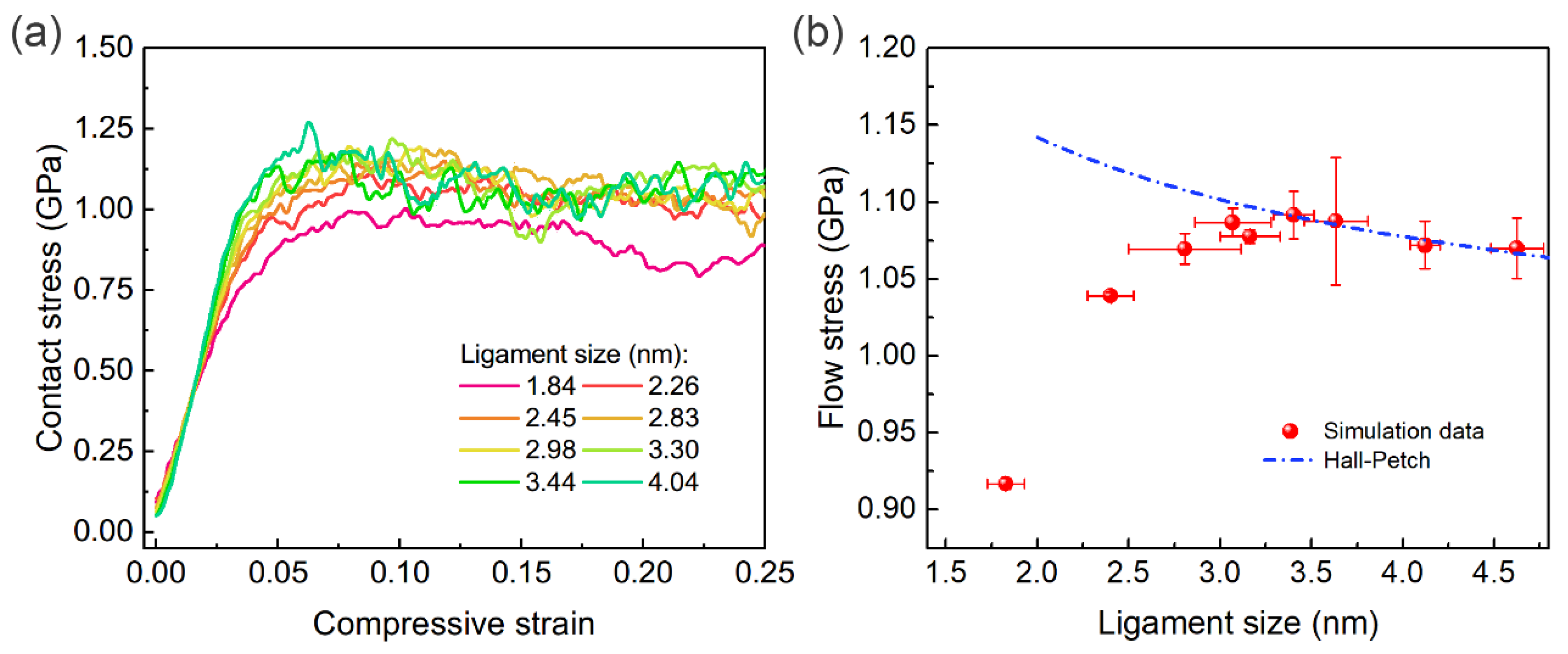
Figure 2a presents the loading curves of contact stress versus compressive strain for a series of nanocubes with varying ligament sizes. For all cases, the contact stress increases linearly with compressive strain in the initial elastic regime (0~0.04). When compressive strain exceeds this range, the linear behavior disappears, indicating the onset of yielding in the nanocubes. In the following stage, the contact stress fluctuates with further accumulation of the compressive strain. However, the overall flow stress of a given nanocube remains nearly constant, suggesting that the plastic deformation saturates immediately after yielding.
Moreover, the overall stress level exhibits a pronounced dependence on ligament size. To quantify the size dependence of strength, Figure 2b plots the mean flow stress (averaged over the strain range of 0.075~0.25) as a function of ligament size. To take account of the influences from the variation in structure, three independent simulations with different spinodoid samples were considered for each ligament size. It is noted that as the ligament size decreases from ~4.62 nm, the mean flow stress keeps increasing. However, after reaching a critical threshold, further reduction in ligament size results in a rapid decrement in contact flow stress. The maximum strength is attained at a ligament size of ~3.30 nm. These characteristics imply that the characteristic length scale of the structure governs the maximum strength of material by regulating the competition between dislocation nucleation/motion and the intrinsic load-bearing capacity of the ligaments.

3.2. Atomic Deformation Mechanisms

To elucidate the size dependence of plasticity, the atomic deformation processes of two representative nanocubes with ligament sizes of 4.62 nm and 1.83 nm were examined. Both the initial dislocation nucleation and subsequent dislocation multiplication under severe deformation are analyzed.

3.2.1. Deformation in Nanocube with a Larger Ligament Size (λ = 4.62 nm)

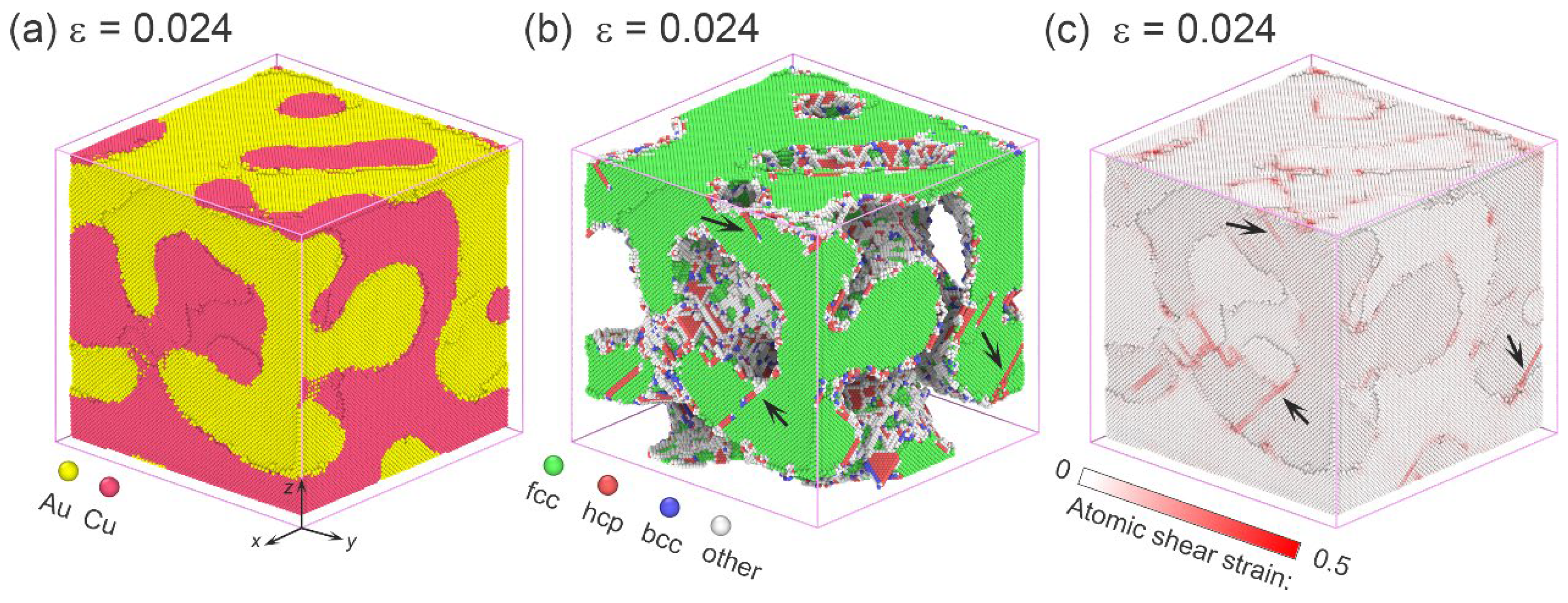
Initial dislocation nucleation in the Au/Cu dual-phase nanocube with a ligament size of 4.62 nm is shown in Figure 3. The Au and Cu phases are separated by smooth, curvature-rich semi-coherent interfaces, which contain dense misfit dislocation embryos due to lattice mismatch (Figure 3a,b). At a compressive strain of 0.024, multiple dislocations are observed to nucleate directly from the interface and propagate into the phase interior (Figure 3b), and similar deformation mechanisms such as dislocation bow-out from interfaces have also been observed in an experimental study [29]. The gliding of these dislocations results in an increase in the local shear strain around interfaces, as evident in Figure 3c. Moreover, Figure 3b demonstrates that the misfit dislocations are dominant at the semi-coherent interfaces, which may act as dislocation sources during subsequent deformation stage.
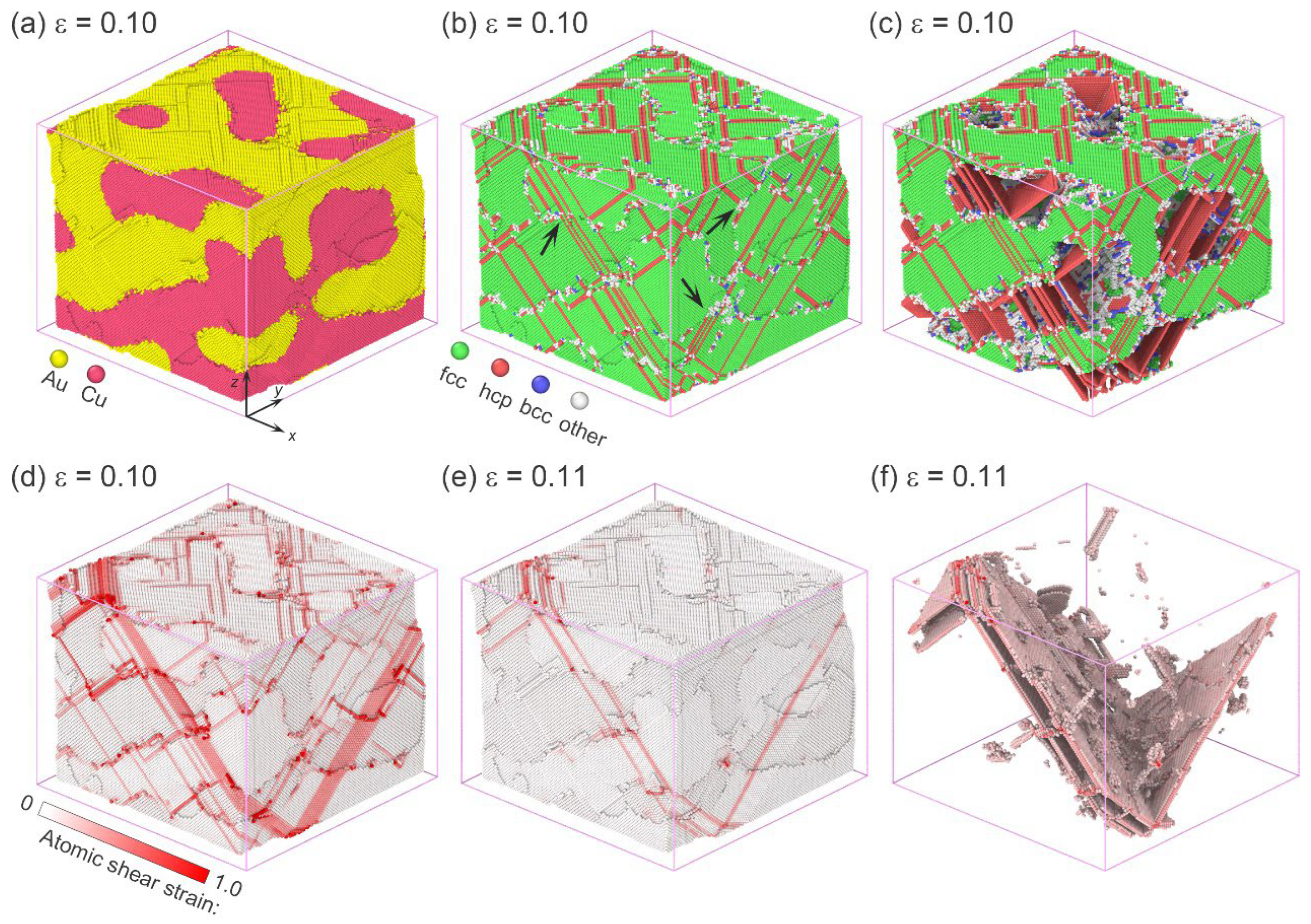
Figure 4 shows the plastic deformation and the associated dislocation activities at a compressive strain of 0.10, representative of the severe deformation stage. Slip trace can be observed around the surface of the deformed nanocube (Figure 4a). With an increasing number of dislocation sources being activated, multiple dislocations are simultaneously nucleated at the curved interfaces. The nucleated dislocations either traverse the ligament and are absorbed at opposite interfaces, or transmit across phase boundaries, as marked in Figure 4b. These behaviors represent common characteristics of dislocation activities around the semi-coherent interfaces in the spinodoid structures [29]. The interaction of dislocations on differently oriented slip planes gives rise to some stable structures, including stair-rod dislocations and Lomer–Cottell junctions [39], as shown in Figure 4c.
By analyzing the distribution of the atomic shear strain at a strain of 0.10 (Figure 4d), the formation of a shear band is revealed, which is characterized by the coexistence of parallel stacking faults and twin boundaries [12]. Figure 4e shows the additional accumulated shear strain when the overall compression strain increases from 0.10 to 0.11. It indicates that shear deformation mainly occurs around the shear band region in the severe deformation stage. The stacking fault associated with this slip is illustrated in Figure 4f. Unlike the relatively flat stacking faults typically observed in deformed single crystal nanocubes [40,41], the stacking faults here are rugged, a feature attributed to interactions between the gliding dislocations and the semi-coherent interfaces during their propagation [42].

3.2.2. Deformation in Nanocube with a Smaller Ligament Size (λ = 1.83 nm)

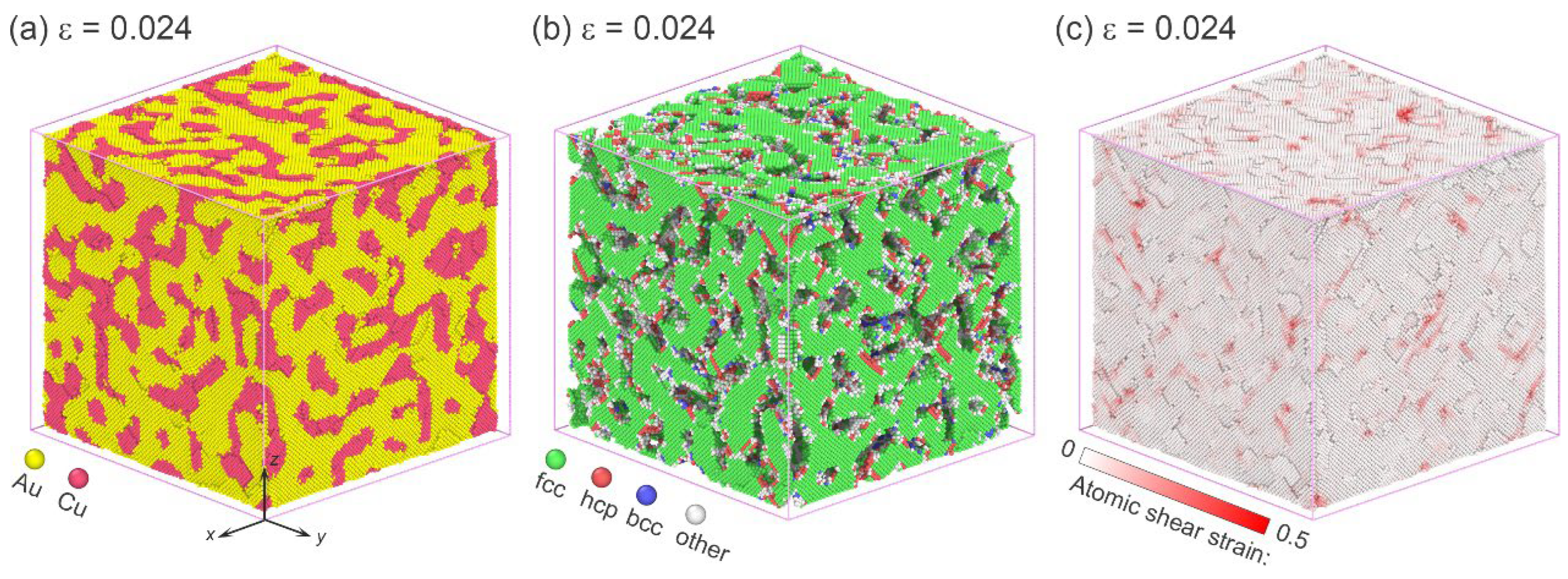
Figure 5 shows the dislocation nucleation in the dual-phase spinodoid nanocube with a smaller ligament size (γ = 1.83 nm). Due to the increased interfacial area, a higher density of misfit dislocations forms inside the nanocube (Figure 5a,b). At the initial stage with a strain of 0.024, there are more dislocations nucleated at the interface than the previous case (Figure 5b,c). Owing to the reduced ligament size, the free path for dislocation gliding within ligaments is restricted, resulting in narrow stacking faults.
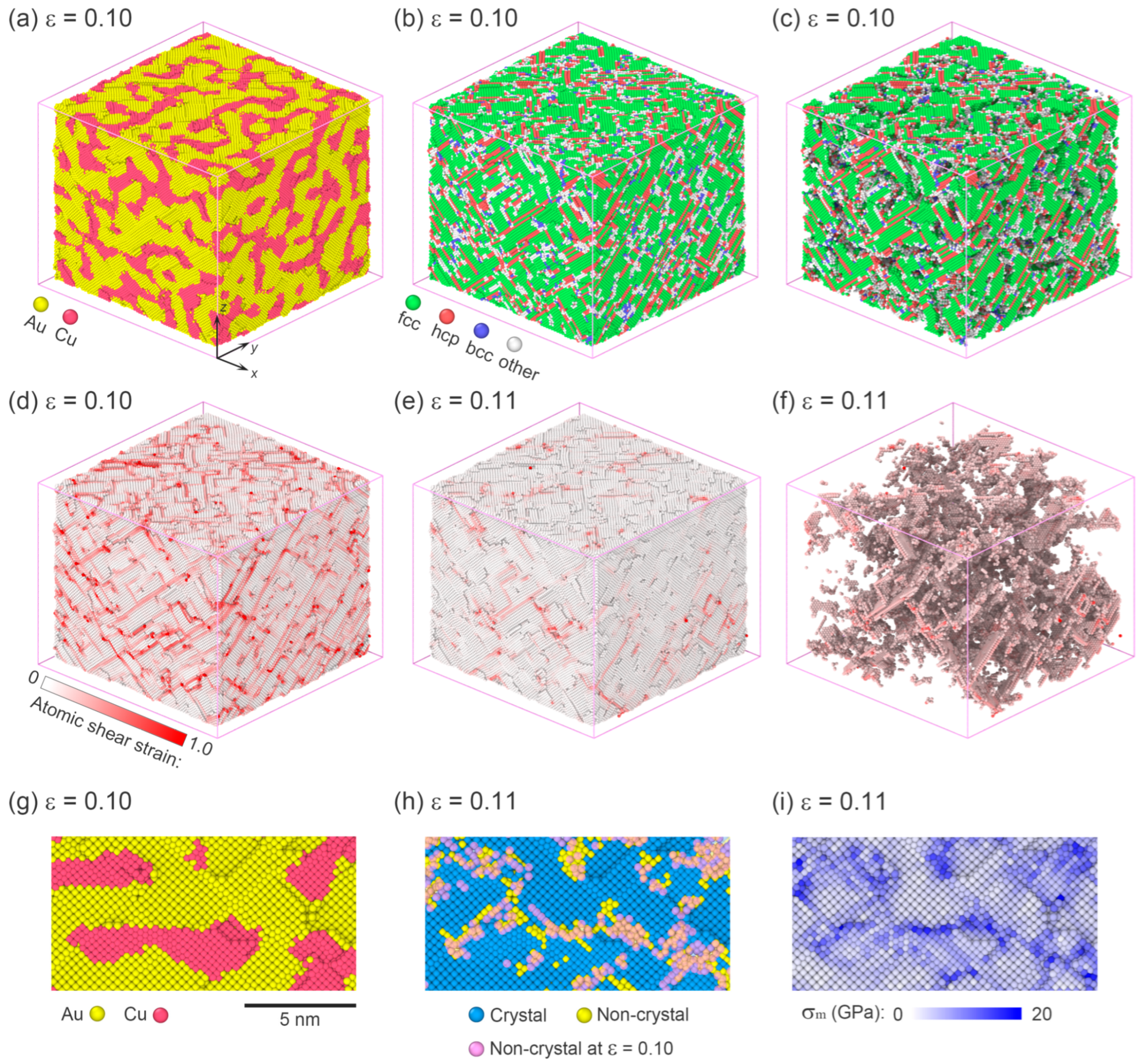
When the compressive strain increases to 0.10, dislocations become almost evenly distributed within the deformed nanocube. The average size of stacking faults and twin boundaries decreases under this condition (Figure 6b,c), which can be attributed to two factors: (i) the smaller ligament size restricts the free path of dislocation gliding within the phase interior; and (ii) the larger interfacial area provides more dislocation nucleation sites, thereby enhancing interactions among stacking faults on different slip planes and impeding the long-distance propagation.
The atomic shear strain distribution further supports these observations. In the nanocube with a smaller ligament size, no dominant shear band is detected (Figure 6d). When the compressive strain increases from 0.10 to 0.11, the additional shear deformation remains uniformly accommodated throughout the nanocube (Figure 6e). The atoms associated with this shear strain are shown in Figure 6f. Notably, plastic deformation is not carried by large, extended stacking faults. Instead, it is sustained by smaller stacking-fault plates and some non-crystal amorphous atoms. The defective atoms, originating from the interfaces, act simultaneously as dislocation sources and sinks, and plays a critical role in accommodating severe plastic deformation. At the interfaces, these non-crystal atoms rearrange during the plastic deformation stage, and atomic rearrangement arises either from dislocation reactions or from plastic deformation confined to the interface [43,44]. To further examine the interfacial plasticity, the deformation around selected local interfaces is analyzed. Figure 6g presents a snapshot of the local interfacial morphology at a strain of 0.10. As the strain increases to 0.11, the non-crystal atoms near the interfaces undergo positional rearrangements, resulting in an increased number of defective atoms in these regions (Figure 6h). The deformation is attributed to the stress concentrations localized around the interfaces (Figure 6i).

3.3. Ligament-Size-Dependent Strengthening Effects

Spinodoid structure governs the dislocation behaviors at the atomic scale, and consequently determines the strength of nanocubes. In the nanocubes with larger ligaments, plastic deformation in the severe deformation stage becomes localized within distinct shear bands, where dislocation nucleating from the interface glides parallel to existing stacking faults and deformation twin boundaries. Similar to nano-twinned crystalline materials [45], this slip mode experiences only weak resistance from stacking faults or twin boundaries. While the dominant resistance to dislocation glide arises from the interfaces. Some stable structures at interfaces, such as stair-rod dislocations and Lomer–Cottrell junctions [39], produce substantial energy barriers that hinder dislocation transmission across the interfaces. With decreasing ligament size, dislocations are more likely to encounter interfaces, thereby increasing the frequency of such interactions. As a result, the material exhibits enhanced strength.
By contrast, the deformation mode changes in the nanocubes with smaller ligaments. As the ligament size decreases, the area of the semi-coherent interface increases, leading to a higher density of misfit dislocations and additional dislocation sources. On one hand, under continued compression, dislocations on different slip planes are simultaneously nucleated. Their accumulation and mutual interactions suppress shear localization, thereby preventing the formation of a dominant shear band. On the other hand, the enlarged semi-coherent interfaces begin to actively participate in plastic deformation, playing a role analogous to grain boundaries in nanocrystalline materials with ultrasmall grain size, which are known to induce softening effects [43,44].
Therefore, the interface exerts two competing effects on the atomic-scale deformation in the dual-phase spinodoid nanocubes: it impedes dislocation motion, thereby strengthening the material, while the interfacial plasticity, such as atomic rearrangements within the interfaces, provides a softening mechanism. In nanocubes with larger ligament sizes, the strengthening effects originating from interfaces dominate the plastic deformation. As the ligament size decreases, the strengthening effects become more pronounced. When the ligament size is reduced beyond a critical threshold, plastic deformation sustained by the interface starts to prevail. When the softening effects surpass the strengthening effects from the interface, the strength of the material decreases with the continuous decrease in ligament size.
Based on the strengthening effect of the ligament and the semi-coherent interface, a Hall–Petch-type [46,47] relationship can be used to characterize the ligament-size-dependent strength of the dual-phase spinodoid nanocubes, which is expressed as
σ = σ 0 + k λ 1 / 2 ,
where σ0 represents the stress required to move the dislocation in ideal crystals, λ is the average ligament size, and k is the Hall–Petch coefficient. In Figure 2b, Equation (2) successfully describes the strengthening stage, and the fitted value of k is 0.31. The critical ligament size corresponding to the maximum flow stress is approximately 3.30 nm. When the ligament size decreases below this critical value, the flow stress decreases with a further refinement of the ligament, indicating an inverse Hall–Petch behavior [46].
It should be noted that, in the present study, a high strain rate on the order of 108 s−1 and a cryogenic temperature of 10 K were adopted in MD simulations. Owing to the effects of strain rate and temperature, the strength of the material under realistic experimental conditions is expected to be notably lower than those observed in MD simulations [48,49]. In addition, higher temperatures would lower the critical stress for dislocation nucleation and gliding around the interfaces [50], thereby activating more dislocation sources and promoting the interfacial plasticity. Consequently, the critical ligament size for the transition from strengthening to softening increases with temperature [29]. Since the critical stress is an intrinsic material property [50], the critical ligament size of the spinodoid nanocube would also depend on elemental composition. Nevertheless, for the dislocation activities that are deterministic, the strengthening effects arising from dislocation–interface interaction and the softening induced by interfacial plasticity will remain. It should be reminded that, besides dislocation nucleation from interfaces, surface dislocations may play a comparable role as the external nanocube size varies, in turn influencing the overall strength. Hence, the ratio of ligament size to nanocube dimension serves as a more appropriate parameter to characterize the system size effect. A systematic investigation considering both the ligament size and the nanocube dimension will be carried out in our future work.
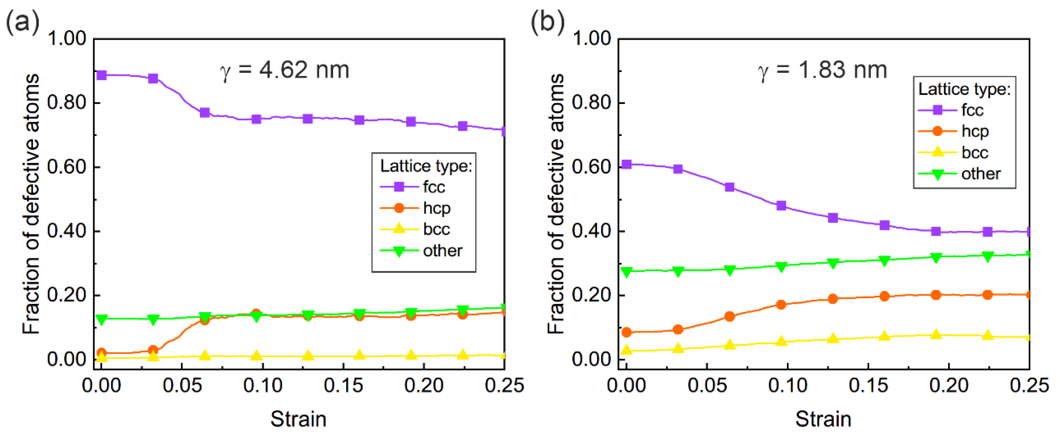
In Figure 7, the fractions of defective atoms classified as bcc, hcp, and non-crystal (labeled as “other”) structures are compared for nanocubes with larger and smaller ligament sizes. It should be noted that main defect atoms are hcp and non-crystal atoms. Initially, misfit dislocations nucleate around the semi-coherent interfaces upon structural relaxation. Following the nucleation of a leading partial dislocation, stacking faults appear, although their area remains small. Prior to loading, both the samples with larger and smaller ligaments sizes exhibit a non-zero fraction of hcp atoms. However, when the ligament size is small, the interfacial area increases significantly, resulting in a higher fraction of hcp atoms. During the loading stage, in the large-ligament nanocubes, the reduced interfacial area limits both structural disorder and available dislocation sources, resulting in a lower atom fraction of the defective non-crystal atoms and an earlier saturation of hcp atoms. By contrast, for the small-ligament nanocubes, the enlarged interfacial area promotes the formation of more defective non-crystal atoms, reflecting enhanced structural disorder at the interfaces. At the same time, the abundance of interfacial sites promotes potential dislocation sources and facilitates the nucleation of dislocations, leading to a higher and more sustained fraction of defective hcp atoms as the nucleated dislocations glide. Furthermore, the interfacial plasticity is primarily driven by local atomic rearrangements at the interfaces, without causing a notable increase in the fraction of “other” atoms, in contrast to the hcp atom fraction associated with dislocation gliding.

4. Conclusions

Classical molecular dynamics simulations were conducted to explore the mechanical responses of Au/Cu dual-phase spinodoid nanocubes under uniaxial compression. The results demonstrate that the ligament size of the spinodoid structure plays a decisive role in governing strength and deformation mechanisms. With decreasing ligament size, flow stress increases following a Hall–Petch-type relation until reaching a critical ligament dimension of ~3.30 nm, beyond which an inverse Hall–Petch trend is observed. Atomic-scale analysis reveals distinct deformation modes across the critical ligament size threshold. In large-ligament nanocubes, severe plastic deformation localizes into shear bands composed of stacking faults and twin boundaries, where dislocations glide parallel to the existing faults and twins. In contrast, small-ligament nanocubes exhibit a relatively homogeneous deformation sustained by short stacking-fault plates and interfacial atoms, reflecting a growing contribution of interfacial plasticity. These findings indicate that the semi-coherent interfaces exert two competing effects: they strengthen the material by impeding dislocation motion, while simultaneously inducing softening through interfacial plasticity when ligament size falls below the critical threshold. Overall, this study highlights the importance of characteristic length scale in dictating the balance between dislocation-mediated and interface-mediated plasticity, thereby providing a mechanistic basis for tailoring the strength and reliability of nanoscale dual-phase materials via the structural design of spinodoid architectures.

Author Contributions

Conceptualization, J.B.; methodology, J.B. and L.Y.; software, J.B. and L.Y.; validation, L.Y.; formal analysis, J.B.; investigation, J.B. and L.Y.; resources, J.B. and L.Y.; data curation, J.B.; writing—original draft preparation, J.B. and L.Y.; writing—review and editing, J.B. and L.Y.; visualization, J.B. and L.Y.; supervision, J.B.; project administration, J.B.; funding acquisition, J.B. All authors have read and agreed to the published version of the manuscript.

Funding

This research was funded by the Natural Science Foundation Research Program of Shaanxi Province, China, grant number 2024JC-YBMS-056.

Data Availability Statement

The original contributions presented in this study are included in the article material. Further inquiries can be directed to the corresponding author.

Conflicts of Interest

The authors declare no conflicts of interest.

References

  1. Amodeo, J.; Pizzagalli, L. Modeling the mechanical properties of nanoparticles: A review. Comptes. Rendus. Phys. 2021, 22, 35–66. [Google Scholar] [CrossRef]
  2. Guo, D.; Xie, G.; Luo, J. Mechanical properties of nanoparticles: Basics and applications. J. Phys. D Appl. Phys. 2014, 47, 013001. [Google Scholar] [CrossRef]
  3. Kim, T.; Myung, S.; Kim, T.H.; Hong, S. Robust single-nanoparticle probe for contact-mode analysis and dip-pen nanolithography. Small 2008, 4, 1072–1075. [Google Scholar] [CrossRef] [PubMed]
  4. Yao, Y.; McDowell, M.T.; Ryu, I.; Wu, H.; Liu, N.; Hu, L.; Nix, W.D.; Cui, Y. Interconnected silicon hollow nanospheres for lithium-ion battery anodes with long cycle life. Nano Lett. 2011, 11, 2949. [Google Scholar] [CrossRef] [PubMed]
  5. Pizzagalli, L.; Godet, J.; Durinck, J.; Brochard, S.; Furstoss, J.; Valencia, F. Twinning and amorphization as plasticity mechanisms in ultra small tungsten nanoparticles. Comp. Mater. Sci. 2025, 258, 114077. [Google Scholar] [CrossRef]
  6. Armstrong, P.; Peukert, W. Size effects in the elastic deformation behavior of metallic nanoparticles. J. Nanopart. Res. 2012, 14, 1288. [Google Scholar] [CrossRef]
  7. Espinosa, I.M.P.; Jacobs, T.D.B.; Martini, A. Atomistic simulations of the elastic compression of platinum nanoparticles. Nanoscale Res. Lett. 2022, 17, 96. [Google Scholar] [CrossRef]
  8. Erbi, M.; Amara, H.; Gatti, R. Tuning elastic properties of metallic nanoparticles by shape controlling: From atomistic to continuous models. Small 2023, 19, 2302116. [Google Scholar] [CrossRef]
  9. Mordehai, D.; Lee, S.; Backes, B.; Srolovitz, D.J.; Nix, W.D.; Rabkin, E. Size effect in compression of single-crystal gold microparticles. Acta Mater. 2011, 59, 5202–5215. [Google Scholar] [CrossRef]
  10. Sharma, A.; Hickman, J.; Gazit, N.; Mishin, E.R.Y. Nickel nanoparticles set a new record of strength. Nat. Commun. 2018, 9, 4102. [Google Scholar] [CrossRef]
  11. Yang, L.; Bian, J.J.; Wang, G.F. Impact of atomic-scale surface morphology on the size-dependency yield stress of gold nanoparticles. J. Phys. D Appl. Phys. 2017, 50, 245302. [Google Scholar] [CrossRef]
  12. Bian, J.J.; Wang, G.F. Atomistic deformation mechanisms in copper nanoparticles. J. Comput. Theor. Nanosci. 2013, 10, 2299–2303. [Google Scholar] [CrossRef]
  13. Salah, S.B.H.; Gerard, C.; Pizzagalli, L. Influence of surface atomic structure on the mechanical response of aluminum nanospheres under compression. Comput. Mater. Sci. 2017, 129, 273–278. [Google Scholar] [CrossRef]
  14. Bian, J.; Zhang, H.; Niu, X.; Wang, G. Anisotropic deformation in the compressions of single crystalline copper nanoparticles. Crystals 2018, 8, 116. [Google Scholar] [CrossRef]
  15. Han, W.Z.; Huang, L.; Ogata, S.; Kimizuka, H.; Yang, Z.C.; Weinberger, C.; Li, Q.J.; Liu, B.Y.; Zhang, X.X.; Li, J.; et al. From ‘smaller is stronger’ to ‘size-independent strength plateau’: Towards measuring the ideal strength of iron. Adv. Mater. 2015, 27, 3385–3390. [Google Scholar] [CrossRef] [PubMed]
  16. Bian, J.J.; Yang, L.; Xin, X.R.; Wang, G.F. Orientation-dependent deformation mechanisms of bcc niobium nanoparticles. Philos. Mag. 2018, 98, 1848–1864. [Google Scholar] [CrossRef]
  17. Kositski, R.; Mordehai, D. Depinning-controlled plastic deformation during nanoindentation of BCC iron thin films and nanoparticles. Acta Mater. 2015, 90, 370–379. [Google Scholar] [CrossRef]
  18. Carlton, C.E.; Ferreira, P.J. In situ TEM nanoindentation of nanoparticles. Micron 2012, 43, 1134–1139. [Google Scholar] [CrossRef]
  19. Mordehai, D.; Rabkin, E. Pseudoelastic deformation during nanoscale adhesive contact formation. Phys. Rev. Lett. 2011, 107, 449. [Google Scholar] [CrossRef]
  20. Bian, J.; Yang, L.; Yuan, W.; Wang, G. Influence of hydrogenation on the mechanical properties of Pd nanoparticles. RSC Adv. 2021, 11, 3115. [Google Scholar] [CrossRef]
  21. Goryaeva, A.M.; Fusco, C.; Bugnet, M.; Amodeo, J. Influence of an amorphous surface layer on the mechanical properties of metallic nanoparticles under compression. Phys. Rev. Mater. 2019, 3, 033606. [Google Scholar] [CrossRef]
  22. Sharma, A.; Amodeo, J.; Gazit, N.; Qi, Y.; Thomas, Q.; Rabkin, E. When more is less: Plastic weakening of single crystalline Ag nanoparticles by the polycrystalline Au shell. ACS Nano 2021, 15, 14061–14070. [Google Scholar] [CrossRef] [PubMed]
  23. Bian, J.; Yuan, W.; Ni, N.; Shao, Z.; Wang, G. Tunable mechanical properties of high-entropy alloy nanoparticles with core-shell structure. Mater. Today Commun. 2025, 49, 113839. [Google Scholar] [CrossRef]
  24. Casillas, G.; Palomares-Baez, J.P.; Rodrıguez-Lopez, J.L.; Luo, J.; Ponce, A.; Esparza, R.; Velazquez-Salazar, J.J.; Hurtado-Macias, A.; Gonzalez-Hernandez, J.; Jose-Yacaman, M. In situ TEM study of mechanical behavior of twinned nanoparticles. Philos. Mag. 2012, 92, 4437–4453. [Google Scholar] [CrossRef]
  25. Valencia, F.J.; Ramirez, M.; Varas, A.; Rogan, J. Understanding the stability of hollow nanoparticles with polycrystalline shells. J. Phys. Chem. C 2020, 124, 10143–10149. [Google Scholar] [CrossRef]
  26. Valencia, F.J.; Pinto, B.; Kiwi, M.; Ruestes, C.J.; Bringa, E.M.; Rogan, J. Nanoindentation of polycrystalline Pd hollow nanoparticles: Grain size role. Compu. Mater. Sci. 2020, 179, 109642. [Google Scholar] [CrossRef]
  27. Kiani, M.T.; Wang, Y.; Bertin, N.; Cai, W.; Gu, X.W. Strengthening mechanism of a single precipitate in a metallic nanocube. Nano Lett. 2019, 19, 255–260. [Google Scholar] [CrossRef]
  28. Xin, T.; Zhao, Y.; Mahjoub, R.; Jiang, J.; Yadav, A.; Nomoto, K.; Niu, R.; Tang, S.; Ji, F.; Quadir, Z.; et al. Ultrahigh specific strength in a magnesium alloy strengthened by spinodal decomposition. Sci. Adv. 2021, 7, 3039. [Google Scholar] [CrossRef]
  29. Guan, H.; Xie, H.; Luo, Z.; Bao, W.; You, Z.; Jin, Z.; Jin, H. Ultrastrong spinodoid alloys enabled by electrochemical dealloying and refilling. Proc. Nat. Acad. Sci. USA 2023, 120, e221477312. [Google Scholar] [CrossRef]
  30. Cahn, J.W.; Hillard, J.E. Free Energy of a nonuniform system. I. interfacial free energy. J. Chem. Phys. 1958, 28, 258–267. [Google Scholar] [CrossRef]
  31. Zhou, X.; Johnson, R.; Wadley, H. Misfit-energy-increasing dislocations in vapor-deposited CoFe/NiFe multilayers. Phys. Rev. B 2004, 69, 144113. [Google Scholar] [CrossRef]
  32. Nosé, S.A. A unified formulation of the constant temperature molecular dynamics methods. J. Chem. Phys. 1984, 81, 511–519. [Google Scholar] [CrossRef]
  33. Hoover, W.G. Canonical dynamics: Equilibrium phase-space distributions. Phys. Rev. A 1985, 31, 1695–1697. [Google Scholar] [CrossRef]
  34. Bian, J.; Yuan, W.; Yang, L.; Ding, Y.; Yu, X.; Shao, Z.; Zhang, H.; Wang, G. Influence of planar defects on the mechanical behaviors of spherical metallic nanoparticles. Phys. Scr. 2025, 100, 015921. [Google Scholar] [CrossRef]
  35. Tsuzuki, H.; Branicio, P.S.; Rino, J.P. Structural characterization of deformed crystals by analysis of common atomic neighborhood. Comput. Phys. Commun. 2007, 177, 518. [Google Scholar] [CrossRef]
  36. Stukowski, A. Structure identification method for atomistic simulations of crystalline materials. Model. Simul. Mater. Sci. 2012, 20, 045021. [Google Scholar] [CrossRef]
  37. Plimpton, S. Fast parallel algorithms for short-range molecular dynamics. J. Comput. Phys. 1995, 117, 1–19. [Google Scholar] [CrossRef]
  38. Stukowski, A. Visualization and analysis of atomistic simulation data with OVITO-the open visualization tool Modelling Simul. Mater. Sci. Eng. 2010, 18, 015012. [Google Scholar]
  39. Abu-Oden, A.; Allaparti, T.; Asta, M. Structure and glide of Lomer and Lomer-Cottrell dislocations: Atomistic simulations for model concentrated alloy solid solutions. Phys. Rev. Mater. 2022, 6, 103603. [Google Scholar] [CrossRef]
  40. Pizzagalli, L.; Gatti, R.; Amodeo, J.; Godet, J.; Durinck, J.; Brochard, S. Relation between strength and local stresses in nanostructures as a function of their size and shape. J. Mech. Phys. Solids 2025, 205, 106306. [Google Scholar] [CrossRef]
  41. Amodeo, J.; Lizoul, K. Mechanical properties and dislocation nucleation in nanocrystals with blunt edges. Mater. Des. 2017, 135, 223–231. [Google Scholar] [CrossRef]
  42. Li, X.; Wei, Y.; Yang, W.; Gao, H. Competing grain-boundary- and dislocation-mediated mechanisms in plastic strain recovery in nanocrystalline aluminum. Proc. Nat. Acad. Sci. USA 2009, 106, 16108–16113. [Google Scholar] [CrossRef]
  43. Schiotz, J.; Jacobsen, K.W. A maximum in the strength of nanocrystalline copper. Science 2002, 301, 1357–1359. [Google Scholar] [CrossRef] [PubMed]
  44. Schiotz, J.; Di Tolla, F.D.; Jacobsen, K.W. Softening of nanocrystalline metals at very small grain sizes. Nature 1998, 391, 561–563. [Google Scholar] [CrossRef] [PubMed]
  45. Li, X.; Wei, Y.; Lu, L.; Lu, K.; Gao, H. Dislocation nucleation governed softening and maximum strength in nano-twinned metals. Nature 2010, 464, 877–880. [Google Scholar] [CrossRef] [PubMed]
  46. Chokshi, A.H.; Rosen, A.; Karch, J.; Gleiter, H. On the validity of the Hall-Petch relationship in nanocrystalline materials. Scr. Metall. 1989, 23, 1679–1684. [Google Scholar] [CrossRef]
  47. Naik, S.N.; Walley, S.M. The Hall–Petch and inverse Hall–Petch relations and the hardness of nanocrystalline metals. J. Mater. Sci. 2020, 55, 2661–2681. [Google Scholar] [CrossRef]
  48. Wang, Y.M.; Ma, E. Temperature and strain rate effects on the strength and ductility of nanostructured copper. Appl. Phys. Lett. 2003, 83, 3165. [Google Scholar] [CrossRef]
  49. Campbell, J.D.; Ferguson, W.G. The temperature and strain-rate dependence of the shear strength of mild steel. Philos. Mag. 1970, 21, 63–82. [Google Scholar] [CrossRef]
  50. Smirnov, B.I. Temperature dependence of the Peierls-Nabarro forces in body-centered cubic metals. Mater. Sci. 1967, 3, 366–367. [Google Scholar] [CrossRef]
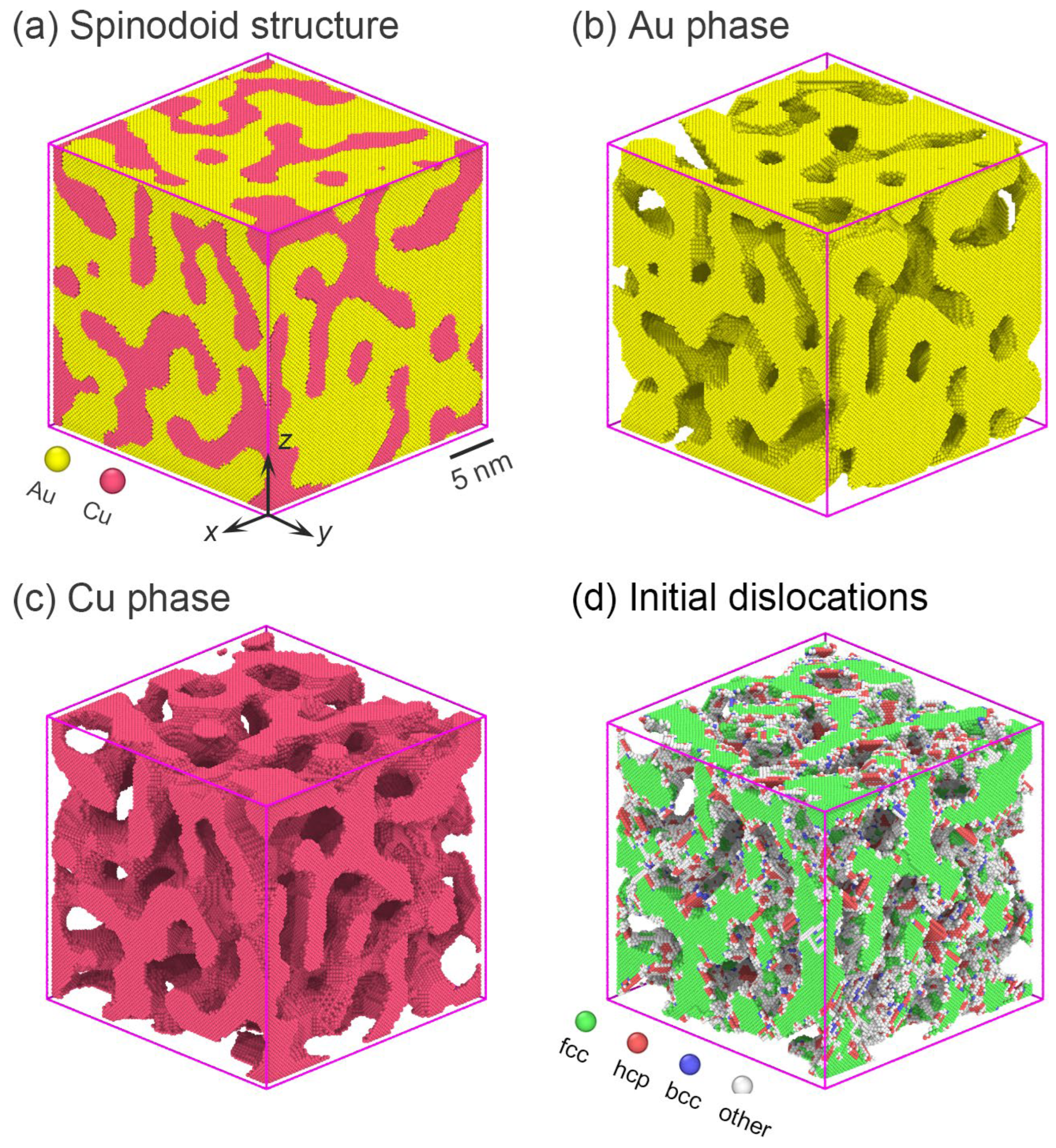
Figure 1. (a) A typical atomic model of the Au/Cu dual-phase spinodoid nanocube with mean ligament size, λ, of ~2.45 nm. (b,c) The structures of Au and Cu phases, respectively. (d) The initial dislocation after structural relaxation. To depict the dislocation structure, surface atoms and fcc atoms in the Au phase are not shown in (d), for clarity.
Crystals 15 00957 g001
Figure 2. (a) The contact stress–strain curves of the nanocubes with different ligament sizes. (b) The flow stress of the nanocube varying with ligament size (error bars denote the fluctuations from three independent simulations).
Crystals 15 00957 g002
Figure 3. Nucleation of dislocations from the semi-coherent Au/Cu interfaces. (a) Atomic morphology of the nanocube. (b) Distribution of the newly nucleated dislocations. To show the interfacial dislocations, surface atoms and the perfect fcc atoms in the copper phase are not shown for clarity. (c) Distribution of the atomic shear strain. The black arrows in (b) indicate three dislocations nucleated from interfaces, and those in (c) indicate the corresponding local shear strain distributions associated with dislocation glide.
Crystals 15 00957 g003
Figure 4. Dislocation gliding during severe deformation. (a) Atomic morphology of the deformed nanocubes. (b,c) The nucleated dislocations at a compressive strain of 0.10. (d) The distribution of the atomic shear strain at an overall strain of 0.10. (e) Distribution of an additional increment in atomic shear strain when the compressive strain increases by 0.01. (f) The associated sheared atomic planes in (e). The three black arrows in (b) indicate the dislocations that either transmit across phase boundaries or are absorbed at the interfaces.
Crystals 15 00957 g004
Figure 5. Nucleation of dislocation from Au/Cu semi-coherent interfaces at a strain of 0.024. (a) The atomic morphology of the nanocube. (b) Distribution of the nucleated dislocations. Atoms in the Cu phase are not shown, for clarity. (c) Distribution of the atomic shear strain.
Crystals 15 00957 g005
Figure 6. Dislocation gliding in severe deformation stage. (a) Atomic morphology of the deformed nanocubes. (b,c) The nucleated dislocations at a compressive strain of 0.10. (d) The distribution of the atomic shear strain at a strain of 0.10. (e) Incremental change in atomic shear strain when the compressive strain increases by 0.01. (f) The sheared atomic planes. To illustrate interfacial plasticity, (g) shows a local interfacial morphology at a strain of 0.10, (h) compares non-crystal atoms (as labeled ‘other’ in (b)) at strains of 0.10 and 0.11, and (i) presents the von Mises stress distribution.
Crystals 15 00957 g006
Figure 7. Evolution of defective atom fraction with compressive strain in nanocubes with (a) a larger ligament size (λ = 4.62 nm) and (b) a smaller ligament size (λ = 1.83 nm).
Crystals 15 00957 g007
Disclaimer/Publisher’s Note: The statements, opinions and data contained in all publications are solely those of the individual author(s) and contributor(s) and not of MDPI and/or the editor(s). MDPI and/or the editor(s) disclaim responsibility for any injury to people or property resulting from any ideas, methods, instructions or products referred to in the content.