Article

Seed-Layer-Assisted Liquid-Phase Epitaxial Growth of YIG Films on Single-Crystal Yttrium Aluminum Garnet Substrates: Evidence for Enhancement in Strain-Induced Anisotropy

1
Physics Department, Oakland University, Rochester, MI 48309, USA
2
Electrical and Computer Engineering, Oakland University, Rochester, MI 48309, USA
3
Microwave Laboratory, Department of Physics, Indian Institute of Technology-Madras, Chennai 600036, India
4
Materials and Manufacturing Directorate, Air Force Research Laboratory, Wright-Patterson Air Force Base, Dayton, OH 45433, USA
*
Author to whom correspondence should be addressed.
Current Address: Shanghai Institute of Microsystems and Technology, Shanghai 200050, China.
Current Address: Hubei Key Laboratory of Micro-Nanoelectronic Materials and Devices, Hubei University, Wuhan 430062, China.
Crystals 2025, 15(11), 953; https://doi.org/10.3390/cryst15110953
Submission received: 28 September 2025 / Revised: 28 October 2025 / Accepted: 1 November 2025 / Published: 4 November 2025
(This article belongs to the Special Issue Single-Crystalline Composite Materials (Second Edition))

Abstract

Epitaxial thick films of yttrium iron garnet (YIG) are ideal for use in microwave devices due to their low losses at high frequencies. This report is on the growth of strain-engineered YIG films by liquid-phase epitaxy (LPE) on yttrium aluminum garnet (YAG) substrates with −3% lattice mismatch with YIG. Since the use of a lattice-matched substrate is preferred for LPE growths, a seed layer of YIG, 370–400 nm in thickness, was deposited by pulsed laser deposition (PLD) on (100), (110), and (111) YAG substrates. The seed layers were stoichiometric with magnetic parameters in agreement with the parameters for bulk single-crystal YIG and with strain-induced perpendicular magnetic anisotropy field Ha = 0.19–0.43 kOe. YIG films, 4 to 8.4 μm in thickness, were grown by LPE at 870 °C on YAG substrates with the seed layers using the PbO+B2O3 flux and annealed in air at 1000 °C. The films were Y-rich and Fe-deficient and confirmed to be epitaxial single crystals by X-ray diffraction. The saturation magnetization 4πMs at room temperature was rather high and ranged from 1.9 kG to 2.3 kG. Ferromagnetic resonance at 5–15 GHz showed the absence of significant magneto-crystalline anisotropy in the LPE films with the line-width ΔH in the range 85–160 Oe, and Ha = 0.27–0.80 kOe which is much higher than for the seed layers. The high magnetization and Ha-values for the LPE films could be partially attributed to the off-stoichiometry. Although the strain due to the film–substrate lattice mismatch contributes to Ha, the mismatch in the thermal expansion coefficients for YIG and YAG is also a likely cause of Ha due to the high growth and annealing temperatures. The LPE-grown YIG films with high strain-induced anisotropy fields have the potential for use in self-biased microwave devices.

1. Introduction

Yttrium iron garnet (YIG), a ferrimagnetic oxide with desirable properties such as a Curie temperature well above room temperature and low magnetic and dielectric losses at high frequencies, has been of fundamental and technological importance since the 1950s [1,2,3]. Due to the very low magnetic damping characterized by an intrinsically low ferromagnetic resonance (FMR) line-width, YIG is used in a variety of FMR-based signal processing devices at microwave frequencies [4]. Thin films of YIG in particular are of interests for compact, planar microwave devices and for magnon-based applications related to information storage, processing, and transmission [5,6]. Early works on thin films involved synthesis by techniques such as chemical vapor deposition (CVD), metal–organic CVD (MOCVD), Radio Frequency (RF) sputtering, and ion beam sputtering [7,8,9,10]. Synthesis efforts on epitaxial, single-crystal thin-film YIG in recent years involved the use of pulsed laser deposition (PLD) [7,8,9,10,11]. The primary focus of the above studies was on the deposition of sub-micron thick YIG films on substrates providing a robust substrate–film lattice mismatch in order to explore its effects on stress-induced magnetic anisotropy.
This report is on the nature of growth-induced magnetic anisotropy in thick epitaxial YIG films grown on yttrium aluminum garnet (YAG) substrates. Several studies in the past were on YIG films with a lattice constant a = 1.2376 nm deposited on YAG substrates with a = 1.2009 nm, leading to a mismatch of −3% in the lattice constants [7,8,9,10,11,12,13,14,15,16]. Due to this mismatch, one anticipates an in-plane compressive strain and an out-of-plane tensile strain resulting in a growth-induced magnetic anisotropy field in YIG. With increasing film thickness, however, one expects relaxation in the strain and a decrease in the magnetic anisotropy. YIG films on substrates, either sputtered or deposited at ambient temperatures, are amorphous and must be annealed at high temperatures [12]. It is, therefore, essential to take into consideration the effects of the thermal expansion mismatch between YIG and YAG on the growth-induced anisotropy. YIG has a much higher thermal expansion coefficient α, ranging from 10 × 10−6 K−1 to 25.7 × 10⁻⁶ K−1, compared to α = 8 × 10⁻⁶ K−1 at 800 K for YAG that could manifest as an in-plane tensile strain and out-of-plane compressive strain upon cooling from high temperatures [13,14,15]. Thus, in addition to lattice mismatch effects, the overall Ha in films of YIG on YAG substrates will depend on the film thickness and deposition/annealing temperatures [15,16,17,18,19].
Past studies on PLD YIG films with a thickness of 18–460 nm reported a perpendicular magnetic anisotropy (PMA) field Ha. In YIG and rare-earth iron garnet (REIG) films on (111) YAG substrates, strain due to lattice mismatch, off-stoichiometry, and high temperature annealing were reported to result in a thickness-dependent Ha [16,17,18]. We recently carried out studies on 55–357 nm thick YIG films prepared by PLD on (100), (110), and (111) YAG substrates [19]. The films deposited at 650 °C were annealed at 1000 °C and characterized by structural and magnetic measurement techniques. The estimated Ha from magnetization and FMR measurements varied from 3 Oe to 450 Oe, decreased with increasing film thickness, and was the highest in films on (100) YAG substrates.
Although most studies in the past dealt with ultrathin YIG films prepared by techniques such as CVD, sputtering, or PLD, much thicker epitaxial YIG films are required for microwave devices such as resonators, filters, and phase shifters [20,21]. In this report, we discuss the results of our study on epitaxial, microns-thick YIG films on single-crystal YAG substrates grown by liquid-phase epitaxy (LPE), a preferred technique for the growth of thick films of ferrites and garnets on lattice-matched substrates [22,23,24,25]. The technique involves dissolving crystal components, Fe2O3 and Y2O3 for YIG films, in a flux of PbO (or BaO) and B2O3. The flux is homogenized at high temperatures and then cooled down to a lower temperature for film growth by dipping the substrate into the flux. It is possible to grow epitaxial films and achieve growth rates as high as 1 μm/min. Due to the difficulties associated with direct LPE growth of YIG film on YAG due to a large lattice mismatch, we followed a two-step process: first. a seed layer of YIG 370–400 nm in thickness was deposited by PLD on single-crystal YAG substrates and characterized in terms of structural and magnetic measurements. Then, YIG films of thickness 4–8.4 μm were grown by LPE techniques on the YAG substrates with the seed layer of YIG. Structural characterization by X-ray diffraction (XRD), electron and scanning probe microscopy, and energy-dispersive X-ray spectroscopy (EDS) confirmed the epitaxial nature of the films. Magnetization and FMR measurements on the films were carried out to determine Ha values that were found to vary from a minimum of 0.27 kOe to 0.8 kOe and were higher than Ha for YIG seed layers on YAG. Details on the synthesis and characterization of seed layers and thick LPE films of YIG on YAG substrates are discussed in the sections that follow.

2. Experiment

2.1. Deposition and Characterization of Seed Layer of YIG on YAG

A seed layer of YIG of thickness 370–400 nm was deposited by PLD as described in Ref. [19]. Briefly, the procedure involved the synthesis of a polycrystalline target of YIG by traditional ceramic techniques by mixing Y2O3 and Fe2O3 in a ballmill, followed by presintering at 950 °C, and final sintering at 1525 °C for 15 h. The deposition of the YIG on vendor-supplied 1 cm × 1 cm × 0.5 mm substrates of (100), (110). and (111) YAG was carried out for 120 min with the substrates kept at 5 cm from the target and heated to 650 °C. A Kf F laser was used for the deposition in an oxygen atmosphere. The films were annealed at 1000 °C for 2 h in an oxygen atmosphere [19].
The structural characterization of the PLD films were carried out by X-ray diffraction, an SEM, and a Park Systems XE-100E scanning probe microscope. The film thickness was measured by an SEM cross-section image and the composition was determined by EDS. Magnetization at room temperature was measured with a Faraday Balance (and could only be carried out for an applied-field H parallel to the film plane). For FMR measurements, an S-shaped coplanar waveguide was used that was excited with microwave power from an Agilent Vector Network Analyzer. Samples of dimensions 2 mm × 5 mm were placed on the waveguide with the static magnetic field H parallel to the sample plane and along its length and perpendicular to the microwave magnetic field. FMR profiles were recorded by two different techniques. For submicron PLD thin films, we employed the modulation of H at 100 kHz to record the profiles of the first derivative of the power absorbed by the sample dP/dH as a function of H for microwave frequencies f = 5–15 GHz. Data on resonance fields Hr were obtained as a function of f from the profiles.

2.2. Liquid-Phase Epitaxial Growth of YIG Films and Characterization

LPE is the technique of choice for the growth of thick single-crystal films of ferrites and garnets and facilitates the rapid growth on lattice-matched substrates [22,23,24,25,26,27]. The growth of YIG films, for example, with a thickness as high as 100 μm could be achieved on gadolinium gallium garnet (GGG) substrates with a substrate–film lattice mismatch of less than 0.5% [22,23,24,25]. The procedure requires the use of a flux such as PbO+B2O3 or BaO+B2O3 in a Pt-crucible in which the crystal components are dissolved and the films are grown by dipping the substrate in the flux. We choose the PbO-based flux due to the anticipated incorporation of small amounts of Pb impurity that was reported to result in an improvement in the magnetic and high-frequency characteristics of YIG films [22,23,28,29]. We grew the films on (100), (110), and (111) YAG with a seed layer of YIG. Ultrapure PbO, B2O3, Y2O3, and Fe2O3 with a purity greater than 99.999 (procured from Alfa Aesar, Stoughton, MA, USA) were mixed in the proper proportions required for stoichiometric YIG films [22]. The molar percentage and weights of the flux and the crystal components are listed in Table 1.
Our LPE growth system consists of a vertical split-furnace. A Pt-crucible filled with the oxides in Table 1 was placed in a 6 cm constant-temperature region of the furnace and heated to 1075 °C and kept at this temperature for 9 h in order to homogenize the solution and then cooled at 1 °C/min to the growth temperature Tg. Past studies on the LPE of YIG reported Tg in the range of 860–880 °C [28,29,30]. The growth rate increases with decreasing Tg values. All our films were grown at 870 °C. Substrates of YAG with a seed layer of YIG held on platinum wires were slowly lowered vertically into the flux to initiate and grow the film for a duration of 30 min. The films grew at a rate of 0.1–0.3 μm/min, depending on the growth temperature Tg. Following the growth, the substrate with the film was raised slowly from the melt, allowed to cool, and cleaned in warm acetic acid to remove any flux. All the grown films were annealed at 1000 °C for 2 h with a heating and cooling rate of 2 °C/min. Structural characterization was carried out by XRD, SEM, and SPM and magnetization was measured with a Faraday balance. For FMR, we obtained profiles of S21 vs. f for a series of H applied either parallel or perpendicular to the plane of the sample placed in an S-shaped coplanar waveguide.

3. Results

3.1. Seed Layers of YIG on YAG Substrates

Substrates of (100), (110), and (111) YAG were procured from vendors and used for the deposition of PLD films of YIG. Atomic force microscopy (AFM) topography images (shown in Figure S1 in the Supplementary Materials) for the YAG substrate showed excellent surface features with a root mean square roughness less than 1.5 nm for the substrates and free of any defects. X-ray diffraction profiles of intensity versus 2θ scans for the PLD YIG films are shown in Figure 1 (and in the Supplementary Figure S2). The data clearly indicate epitaxial single-crystal films of YIG on all three YAG substrates. The film thicknesses were determined by cross-section SEM images as shown in Figure 2a for the 370 nm film on the (100) YAG substrate and in Figure S3 in the Supplementary Materials for the 400 nm film on the (110) YAG. The thickness of the film on the (111) YAG determined by a similar SEM image was 380 nm.
A representative AFM topography image for the film on the (100) YAG substrate shown in Figure 2b indicated a smooth surface and the phase image of magnetic force microscopy shown in Figure 2c shows stripe domains, typical of films with a perpendicular growth-induced anisotropy for the film. Similar magnetic force microscopy (MFM) phase images for the films on the (110) and (111) YAG also showed stripe domains (Figures S4 and S5 in the Supplementary Materials). The chemical compositions for the films were determined to be Y3.0±0.02Fe5.0±0.02O12 (Supplementary Figures S6 and S7) by EDS. The above composition is the average value from four different spots on the film surface. Aluminum impurity was not detected in the films, and high-temperature annealing, thus, did not lead to the diffusion of Al from the substrate to the film.
Magnetic characterization on the PLD films were carried out by measuring the magnetization M and FMR at room temperature. Figure 3 shows 4πM vs. H data obtained with a Faraday Balance. The data are for H parallel to the sample plane and the technique does not allow for measurements for H perpendicular to sample plane. Data on 4πM vs. H for H up to 1 kOe are shown in Figure S8 in the Supplementary Materials. The error in H was ±2 Oe for H < 100 Oe and ±5 Oe at higher fields. The error in the magnetization, due to the 1% error in the film mass, was ±20 G. A sharp increase in M with H to saturation for H > ~30 Oe was observed for all the films. Upon a decrease in H to zero and the reversal of the H-direction, a coercive field less than 5 Oe was measured for the films.
The saturation magnetization ranged from a minimum of 1.84 kG for the film on the (110) YAG to a maximum of 1.95 kG for the film on the (100) YAG.
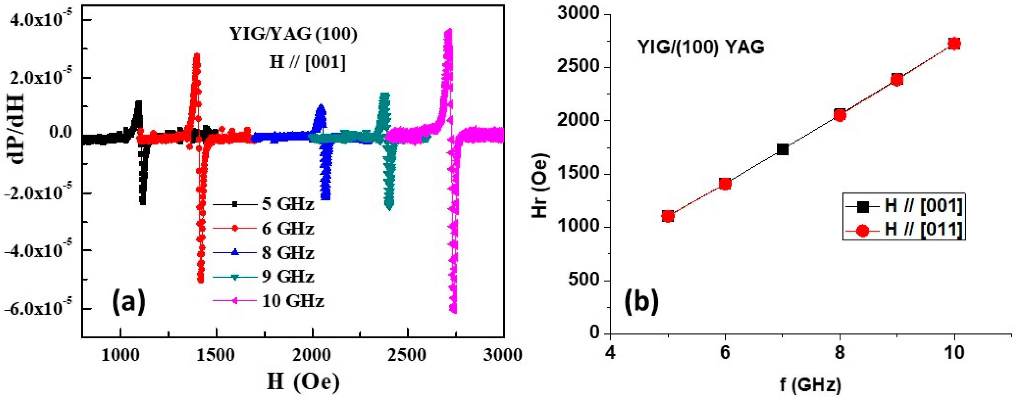
FMR measurements were carried out by placing the sample in a coplanar waveguide and recording the first derivative of the power-absorbed dP/dH as a function of H. Such profiles for the film on the (100) YAG for a series of microwave frequencies f = 5–10 GHz and for H parallel to the sample plane and along [001] axis of the YIG film are shown in Figure 4a. The resonance field Hr increased with increasing f as shown in Figure 4b. Similar measurements were carried out for the in-plane H parallel to the [011] axis of the YIG film and the measured variation in Hr with f are also plotted in Figure 4b. It is clear from the data that Hr is independent of the in-plane direction of H.
It is, therefore, evident from the data in Figure 4b that the magnetocrystalline anisotropy field Hc is negligible for the seed YIG film on the (100) YAG. One may fit the data on f vs. Hr to the Kittel’s resonance condition for in-plane H,
f2 = γ2 H (H + 4πMeff)
with
4πMeff = 4πMs + Ha.
Here, γ is the gyromagnetic ratio. The estimated values of the parameters γ and Ha from the fitting (Figure S9 in the Supplementary Materials) and measured 4πMs are γ = 2.94 GHz/kOe and Ha = −0.43 kOe. Thus, a negative value for Ha indicates that the anisotropy field is perpendicular to the film plane. The f-dependence of the peak-to-peak resonance line-width ΔH is shown in Figure S9 in the Supplementary Materials and ΔH varied from a minimum of 20 Oe at 5 GHz to a maximum of 25 Oe at 10 GHz for H // [001]. For H along [011], however, ΔH was higher and ranged from 32 Oe to 36 Oe for the same frequency range.
The films on the (110) and (111) YAG substrates were also characterized by similar FMR measurements for the in-plane H and the results are shown in Figures S10–S12 in the Supplementary Materials. The line-widths in Figures S9, S11 and S12 were estimated from dP/dH vs. H profiles and the error is 5 Oe. The parameters of importance obtained from the magnetic and FMR measurements are listed in Table 2. Key inferences from the parameters in Table 2 are as follows:
(i) The magnetocrystalline anisotropy field is negligibly small for all of the PLD YIG films. (ii) The 4πMs values for the films are in general agreement with the expected value of 1.78 kG for YIG. (ii) The γ-values of 2.89–2.94 GHz/kOe are close to the spin-only value of 2.98 GHz/kOe for YIG. (iii) Ha values in the range 0.19 kOe to 0.43 kOe are the smallest for the film on the (111) YAG and the highest for the YIG film on the (100) YAG substrate. (iv) ΔH is the smallest for the film on the (100) YAG and the highest for the one deposited on the (110) YAG and increases with increasing frequency.

3.2. LPE YIG Films on YAG with Seed Layer of YIG

Next, we consider the structural and magnetic characterization of LPE films of YIG grown on the YAG substrates with the seed layer of YIG. The X-ray diffraction data for the annealed films are shown in Figure 5 (and in Figures S13 and S14 in the Supplementary Materials) and the films were found to be epitaxial single crystals with the same orientation as the seed layer and YAG substrates. The lattice constants estimated from the XRD data are a = 1.2414 nm for YIG and a = 1.2018 nm for YAG and a film–lattice mismatch of −3.2%. The chemical compositions determined by EDS (Figure S15 in the Supplementary Materials) revealed that the films are yttrium-rich and iron-poor, Y3.195Fe4.805O12, with a Y-to-Fe ratio of 0.665 versus the expected 0.6 for stoichiometric films. Past studies reported a much higher deviation in the Y/Fe ratio, in the range of 0.74–0.85, for films prepared by a variety of techniques, including MOCVD [11]. Any excess Y in YIG is expected to result in an increase in the a-value since Y has a larger ionic radius than trivalent Fe. The anticipated increase, in fact, is evident from the estimated a-value of YIG, i.e., 1.2414 nm vs. the literature value of 1.2376 nm [31,32,33,34,35]. The film thickness was determined from the mass of the LPE film as well as from the cross-section SEM images (shown in Figures S16 and S17 in the Supplementary Materials). The SEM images showed some variation in film thickness along its length, similar to past reports [34], possibly due to the vertical dipping growth process we used. The estimated average thicknesses from SEM images (including the thickness of PLD YIG) are 9.5 μm, 5.0 μm, and 4.8 μm, respectively, for the films on the (100), (110), and (111) YAG. However, the corresponding average thicknesses estimated from the film mass, 8.4 μm, 4.0 μm, and 4.1 μm, respectively, are likely much more accurate than from SEM images and are listed in Table 3. The scanning probe microscopy (SPM) images showed defect-free surface profiles as in Figure 6 and the MFM phase images showed stripe domains in the films, indicative of a uniaxial anisotropy field perpendicular to the sample plane.
Magnetization at room temperature was measured as a function H and the results are shown in Figure 7 for −200 Oe < H < 200 Oe and in Figure S18 for −3 kOe < H < 3 kOe. A rapid increase in M with H to the saturation value for H > 300 Oe was observed for all the films and the coercive field was less than 10 Oe. The saturation values of the magnetization, including the seed layers of YIG, are 29.6, 34.9, and 35.6 emu/g for the films on the (100), (110), and (111) YAG substrates, respectively. The corresponding 4πMs values are 1.92, 2.27, and 2.31 kG and is higher than the 1.7 kG reported for bulk single crystals of YIG [35]. Ms is the smallest for the film on the (100) YAG and the highest for the YIG film on the (111) YAG.
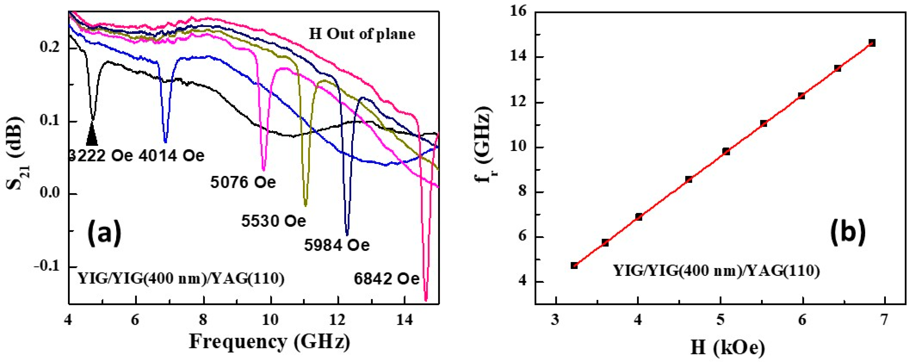
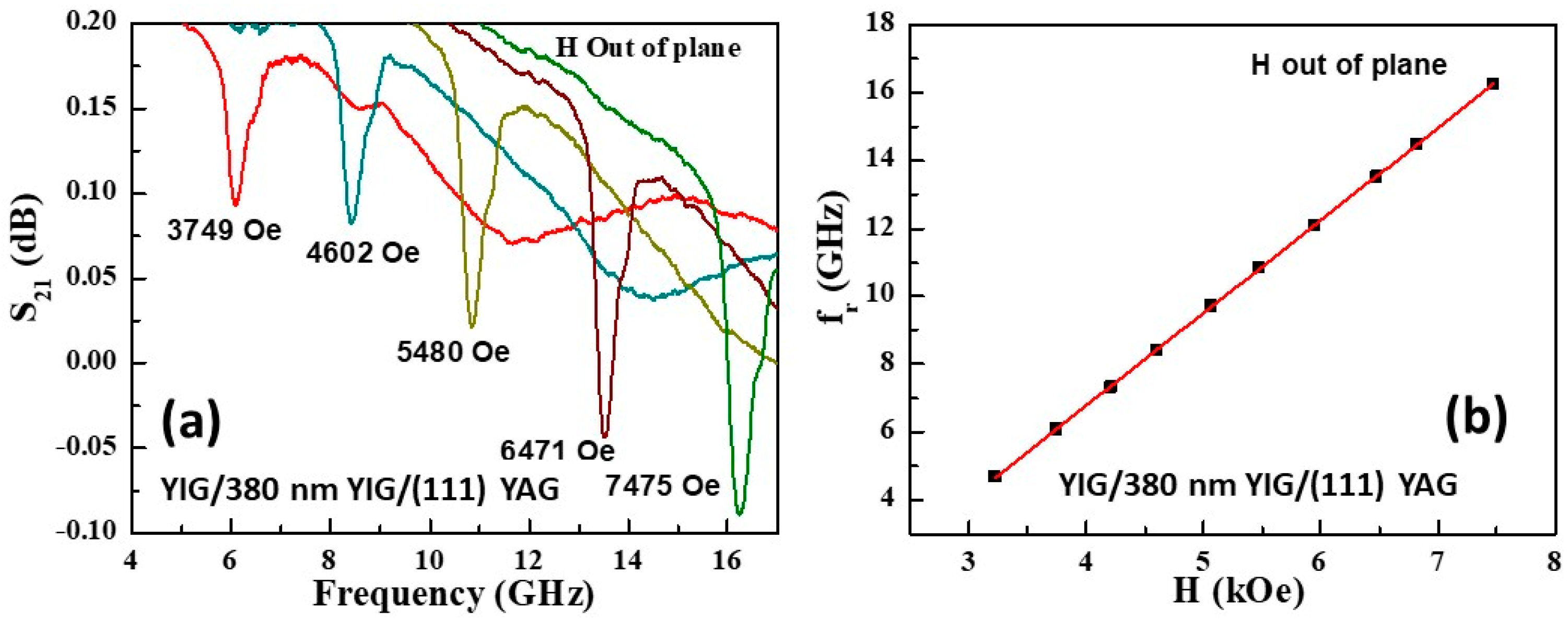
Ferromagnetic resonance measurements on the films were carried out using an S-shaped coplanar waveguide excited with microwave power from a vector network analyzer. The sample was placed in the waveguide so that the rf magnetic field was perpendicular to the static magnetic field H. Measurements were carried out for H both perpendicular and parallel to the sample plane. The scattering matrix parameter S21 was recorded as a function of frequency f for a series of H and the FMR manifested as a dip in S21. Figure 8 shows S21 vs. f profiles for a series of H applied perpendicular to the sample plane for the YIG film on the (100) YAG. The transmitted power shows a dip at FMR frequency fr and it shifts to a progressively higher frequency with increasing H, as expected. Figure 8 also shows fr as a function of H that has a linear dependence on the H-value.
One may fit the fr vs. H data to the Kittel equation for out-of-plane H:
fr = γ (H − 4πMeff),
and 4πMeff is defined in Equation (2). The linear fit to the fr vs. H data shown in Figure 8 yielded values of γ = 2.74 GHz/kOe and 4πMeff = 1.65 kG.
We carried out similar FMR measurements on the LPE YIG films grown on the (110) and (111) YAG substrates and the results are shown in Figure 9 and Figure 10. The profiles in Figure 9 for the film on the (110) YAG show a narrow frequency width compared to the film on the (100) YAG and the estimated parameters from the linear fit to the fr vs. H data are γ = 2.74 GHz/kOe and 4πMeff = 1.50 kG. The film on the (111) YAG shows the broadest FMR absorption profiles as seen in Figure 10 and the linear fit to fr dependence on H in the figure yielded γ = 2.74 GHz/kOe and 4πMeff = 1.51 kG. The magnetic parameters for the films estimated from FMR are listed in Table 3.
One may determine the FMR half-power frequency width Δf by estimating the S21 values for the half-power from the profiles in Figure 8, Figure 9 and Figure 10 using the following expression [36]:
S21,Δf = 10 log10 (10 S21,b/10 + 10 S21,fr/10)/2 dB,
where S21,b and S21,fr are the base-line and resonance values of S21. The line-width ΔH is related to Δf by the following expression:
ΔH = Δf/(2.98 GHz/kOe).
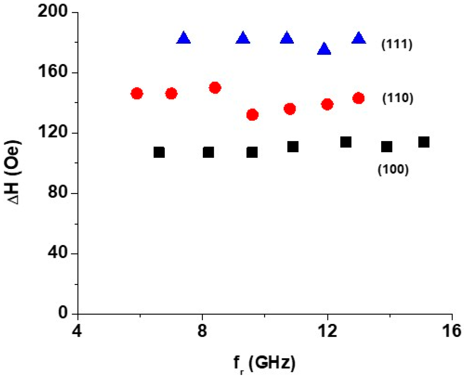
Variations in ΔH with fr are shown in Figure 11 and also listed in Table 3. The measurement error in the line-width data in Figure 11 was estimated from S21-values in the FMR profiles and using Equations (4) and (5). The error in the estimated line-width is ±10% of the values in Figure 11.
The line-width for the (110) film ranges from 85 Oe to 90 Oe and is the smallest amongst the three LPE films and is of the same magnitude as that for the 400 nm PLD YIG film on the (110) YAG. The (111) LPE film shows the highest ΔH value. The causes of the higher ΔH for the LPE films compared to the thin PLD films are discussed in the next section. We also carried out FMR measurements on LPE films for H parallel to the sample plane and the results on S21 vs. f for a series of H-values and fits to f vs. H are shown in Figures S19–S21. The results in Figure S22 on the dependence of the resonance frequency on the in-plane H-direction for the film on the (110) YAG clearly indicate the absence of magnetocrystalline anisotropy in the thick LPE films, a similar observation as for the PLD seed layers of YIG.

4. Discussion

Our approach detailed in this report for the growth of epitaxial YIG films on YAG substrates with a −3% mismatch was to use YAG substrates with a seed layer of YIG deposited by PLD techniques. The seed layers with thickness 370–400 nm deposited at 650 °C on the YAG substrates had to be annealed at 1000 °C in order to obtain fully crystalized films with a homogeneous composition and the desired low losses at high frequencies [12,19]. The X-ray diffraction data (Figure 1) confirmed the epitaxial nature of the films and the SPM images showed defect-free surfaces and stripe magnetic domain structures expected for films with out-of-plane uniaxial anisotropy (Figure 2). The EDS measurements confirmed a stoichiometric composition for the films with a Y-to-Fe ratio of 0.6.
The saturation magnetization at room temperature 4πMs for the films (Figure 3 and Table 2) ranged from 1.84 kG to 1.95 kG, in general agreement with the expected value of 1.78 kG reported for bulk single crystals of YIG [35]. The gyromagnetic ratio γ = 2.89–2.94 GHz/kOe for the films from the FMR measurements at 5–10 GHz for the in-plane H was in agreement with the value of 2.98 GH/kOe for YIG [35] (Figure 4). The uniaxial anisotropy field Ha determined from FMR (Table 2) ranged from 190 Oe for the film on the (111) YAG to 430 Oe for the film on the (100) YAG. In addition to the substrate–film lattice mismatch, both the high-temperature deposition of the film and post-deposition annealing are expected to contribute to Ha due to the significant difference in the thermal expansion coefficients for YIG and YAG [7,13,17]. The FMR profiles did not show a measurable variation in the resonance field Hr with the in-plane H-direction for the (100) and (110) YIG films and was indicative of negligible magneto-crystalline anisotropy field Hc for the films. Past studies on PLD films on YAG substrates, however, reported Hc ~ 47 Oe for 9.6 nm-thick films that increased to 95 Oe for 37 nm-thick film [17].
In our recent study on 55–380 nm-thick YIG films deposited on single-crystal YAG substrates by PLD, we reported the following values of the RT magnetic parameters: 4πMs = 1.67–1.98 kG, γ = 2.70–2.80 GHz/kOe, and Ha decreasing with increasing film thickness from a maximum of 450 Oe to a minimum of 3 Oe [19]. The magnetic parameters in Table 2 for the 370–400 nm PLD YIG films are in general agreement with the values in Ref. [19]. The FMR line-width ΔH (Table 2) showed significant dependence on the in-plane H direction, increased with increasing frequency, with the lowest value for the (100) YIG film and the highest for the film on (110) YAG.
Thick YIG films were grown by LPE on the YAG substrates with the seed YIG layers. The films were grown using the PbO+B2O3 flux and crystal components listed in Table 1 and by the vertical dipping of the substrates at 870 °C. The films were confirmed to be epitaxial single crystals by XRD (Figure 5). A chemical composition analysis by EDS showed the deviation from stoichiometry and the films were Y-rich and Fe-deficient with a Y-to-Fe ratio of 0.67 versus the desired value of 0.6. Similar Y-rich and Fe-deficient films with a much higher Y-to-Fe ratio of 0.74 to 0.85 was reported for YIG films on YAG substrates prepared by other techniques such as MOCVD [11]. MFM phase images for the 4 to 8.4 μm-thick films showed stripe domains that are indicative of a uniaxial anisotropy field perpendicular to the film plane (Figure 6). Room-temperature M vs. H data (Figure 7) revealed a soft magnetic behavior with the coercive fields as small as 5 Oe. The saturation magnetization 4πMs = 1.92, 2.27, and 2.31 kG, respectively, for the films on the (100), (110) and (111) YAG substrates, are higher than the expected value of 1.78 kG for YIG (Table 3). A possible cause of the higher magnetization could be the deviation in the chemical composition for the LPE films leading to a mixed valency for Fe. A much higher 4πMs of 2538 G was reported for thick YIG films deposited by MOCVD on YAG substrates and was attributed to the presence of both divalent and trivalent Fe in the garnet [8]. In a report on ultrathin YIG films, a rather high 4πMs = 2100 G on the GGG substrate was attributed to an off-stoichiometry in the films [37], but the cause of a similar high magnetization of 2.2 kG for a stoichiometric YIG film on GGG in another report was unknown [38].
Ferromagnetic resonance measurements over the frequency range of 3–16 GHz for both out-of-plane and in-plane H were carried out for the determination of the magnetic parameters, in particular, the growth induced anisotropy field Ha for the LPE films. The magnetic parameters estimated from out-of-plane FMR are listed in Table 3. In-plane FMR (Figures S19–S21) also yielded parameters in agreement with the values estimated for out-of-plane H. The most important inference from FMR for in-plane H is the absence of any dependence of fr vs. H on the direction of H (Figure S22) that implies negligible magneto-crystalline anisotropy for the LPE film, a similar observation as that for the PLD seed layers. The gyromagnetic ratio (in Table 3) γ ~ 2.74 GHz/kOe for the LPE films is 8% smaller than the expected value of 2.98 GHz/kOe. The anisotropy field Ha for the LPE films determined from FMR values of 4πMeff (=4πMs + Ha) and the saturation magnetization are much higher than that for the thin PLD films except for the film on the (100) YAG. The line-width ΔH for the LPE films is much higher than that for the seed PLD films except for the film on the (110) YAG.
Liquid-phase epitaxy is a mature and preferred technique for the growth of YIG primarily on lattice-matched substrates such as GGG with a substrate–film mismatch of less than 1% [22,23,24,25,26,27,28]. Stoichiometric YIG films on GGG are reported to have RT 4πMs = 1.78 kG, γ = 2.98 GHz/kOe, ΔH as small as 0.25 Oe, and uniaxial perpendicular anisotropy field Ha that depends on the film thickness [24,28]. There have been no reports so far on the direct LPE growth of YIG on YAG substrates, possibly due to a much higher substrate–film lattice mismatch of −3%. In this work, we have demonstrated the viability of the growth of thick YIG films with the aid of a thin seed layer of YIG on YAG. Although one expects the relaxation of the strain due to the film–substrate lattice mismatch with increasing film thickness and a decrease in Ha in the thick films, an enhancement in Ha compared to the thin seed layers is measured in our LPE films. The growth-induced anisotropy field, a key parameter of interest for the use of self-biased YIG films in miniature microwave devices, is as high as 0.8 kOe in the LPE films on YAG.
There are several contributing factors to the enhancement in Ha, including the lattice mismatch, deviation from stoichiometry for the YIG film, and mismatch in thermal expansion coefficients. The linear thermal expansion coefficient α for YAG is reported to be 8 × 10⁻⁶ K−1 at 800 K, whereas YIG has a higher α with reported values ranging from 10 × 10−6 K−1 to 25.7 × 10⁻⁶ K−1 [13,14,15]. Thus, the mismatch in α-values is a key factor in the overall strain induced in the LPE films since (i) the growth at 870 °C is followed by the rapid cooling of the film and (ii) the post-growth annealing of the film is carried out at an even higher temperature of 1000 °C. Several past studies also suggested the mismatch in α to be an important source of strain and Ha in YIG films on YAG. The mismatch in α was the primary source of strain in a YIG film grown by CVD on YAG [7]. The recrystallization in a PLD YIG film on YAG was found to induce tensile strain at the interface, giving rise to a perpendicular anisotropy field [17]. Similarly, the strain in rare-earth garnet films on YAG was reported to arise from a combination of lattice and thermal expansion mismatch and off-stoichiometry [16].

5. Conclusions

The successful growth of epitaxial, single-crystal films of YIG by liquid-phase epitaxy on (100), (110), and (111) YAG substrates was achieved with the aid of a seed layer of YIG of thickness 370–400 nm deposited by PLD techniques. The PLD films were found to be stoichiometric with the magnetization and γ-values in general agreement with values for bulk single crystals of YIG and negligible magneto-crystalline anisotropy. The strain induced perpendicular anisotropy field Ha ranged from 190 Oe for the film on the (111) YAG to 430 Oe for YIG on the (100) YAG. The FMR line-width ΔH values were in the range of 20–86 Oe. LPE films of YIG of average thickness 4–8.4 μm grown on YAG substates with the seed layer and annealed at high temperatures were found to be off-stoichiometric with a 4–6.6% deviation in Y and Fe contents and with a high RT 4πMs of 1.92–2.31 kG. The magnetocrystalline anisotropy was negligibly small and, in spite of a factor of 10–20 higher thickness than the seed layers, the strain anisotropy Ha was as high as 0.8 kOe in the LPE films. The high magnetization and Ha are attributed to off-stoichiometry and strain due mismatches in the lattice constants and thermal expansion coefficients for YIG and YAG.

Supplementary Materials

The following supporting information can be downloaded at: https://www.mdpi.com/article/10.3390/cryst15110953/s1, Figure S1: AFM topography for YAG substrate. Figure S2: XRD data for PLD films of YIG on YAG substrate. Figure S3: SEM cross-section image for PLD YIG on YAG. Figures S4 and S5: MFM amplitude and phases for PLD YIG on YAG. Figures S6 and S7: EDS data for PLD films on YAG. Figure S8: Magnetization vs. H for H up to ±1 kOe for PLD YIG films. Figures S9–S12: FMR profiles, fittings to resonance equation, and line-width data for PLD YIG films on YAG. Figures S13 and S14: XRD data for LPE YIG films. Figure S15: EDS data for LPE YIG film. Figures S16 and S17: Cross-section SEM images for LPE YIG films. Figure S18: M vs. H for LPE films for H up to ±3 kOe. Figures S19–S22: FMR profiles for in-plane H and line-width data for LPE YIG films.

Author Contributions

Conceptualization, G.S. and V.S.; methodology, G.S., V.S. and M.R.P.; investigation, C.K., R.B., Y.L., P.Z., S.M., A.B., H.Q., D.X., S.S., V.S. and M.R.P.; data curation, C.K., R.B. and G.S.; writing—original draft, G.S.; writing—review and editing, G.S.; visualization, S.M. and A.B.; supervision, R.B., G.S., V.S. and M.R.P.; project administration, G.S., H.Q., V.S. and M.R.P.; funding acquisition, H.Q., G.S., V.S. and M.R.P. All authors have read and agreed to the published version of the manuscript.

Funding

The research at Oakland University and at the Indian Institute of Technology-Madras, India was supported by a grant under the collaborative NSF (grant # ECCS-2415328) and Government of India-Ministry of Electronics and Information Technology (MeitY-Grant # 3149158) program. The efforts at Oakland University were also supported by grants from the National Science Foundation (ECCS-EAGER-2236879) and the Air Force Research Laboratory (AFRL—Award No. FA9550-23RXCOR001). The research at AFRL was supported by a grant from the AFOSR (Award No. FA9550-23RXCOR001).

Data Availability Statement

The original contributions presented in this study are included in the article and in the Supplementary Materials. Further inquiries can be directed to the corresponding author.

Conflicts of Interest

The authors declare no conflicts of interest.

References

  1. Mallmann, E.J.J.; Sombra, A.S.B.; Goes, J.C.; Fechine, P.B.A. Yttrium iron garnet: Properties and applications review. Solid State Phenom. 2013, 202, 65–96. [Google Scholar]
  2. Arsad, A.Z.; Zuhdi, A.W.M.; Ibrahim, N.B.Y.; Hannan, M.A. Recent advances in yttrium iron garnet films: Methodologies, characterization, properties, applications, and bibliometric analysis for future research directions. Appl. Sci. 2023, 13, 1218. [Google Scholar] [CrossRef]
  3. Schmidt, G.; Hauser, C.; Trempler, P.; Paleschke, M.; Papaioannou, E.T. Ultra thin films of yttrium iron garnet with very low damping: A review. Phys. Status Solidi (b) 2020, 257, 1900644. [Google Scholar] [CrossRef]
  4. Wigen, P.E. Microwave properties of magnetic garnet thin films. Thin Solid Film. 1984, 114, 135–186. [Google Scholar] [CrossRef]
  5. Serga, A.A.; Chumak, A.V.; Hillebrands, B. YIG magnonics. J. Phys. D Appl. Phys. 2010, 43, 264002. [Google Scholar] [CrossRef]
  6. Sheng, L.; Chen, J.; Wang, H.; Yu, H. Magnonics based on thin-film iron garnets. J. Phys. Soc. Jpn. 2021, 90, 081005. [Google Scholar] [CrossRef]
  7. Zeyfang, R. Stresses in Epitaxially Grown Single-Crystal Films: YIG on YAG. J. Appl. Phys. 1970, 41, 3718–3721. [Google Scholar] [CrossRef]
  8. Aida, H.; Watanuki, R.; Ito, A. High-speed epitaxial growth of Y3Fe5O12 thick film with high magnetization on (4 2 0) Y3Al5O12 substrate using metal-organic chemical vapor deposition. Mater. Lett. 2020, 276, 128228. [Google Scholar] [CrossRef]
  9. Cooper, J.F.K.; Kinane, C.J.; Langridge, S.; Ali, M.; Hickey, B.J.; Niizeki, T.; Uchida, K.; Saitoh, E.; Ambaye, H.; Glavic, A. Unexpected structural and magnetic depth dependence of YIG thin films. Phys. Rev. B 2017, 96, 104404. [Google Scholar] [CrossRef]
  10. Yoshihara, Y.; Ishiyama, K.; Watanabe, T.; Lim, P.B.; Inoue, M.; Ross, C.A.; Goto, T. Growth of magnetooptical cerium-substituted yttrium iron garnet on yttrium aluminum garnet using ion beam sputtering. Appl. Phys. Lett. 2023, 123, 112404. [Google Scholar] [CrossRef]
  11. Sposito, A.; May-Smith, T.C.; Stenning, G.B.G.; De Groot, P.A.J.; Eason, R.W. Pulsed laser deposition of high-quality μm-thick YIG films on YAG. Opt. Mater. Express 2013, 3, 624–632. [Google Scholar] [CrossRef]
  12. Sailler, S.; Skobjin, G.; Schlörb, H.; Boehm, B.; Hellwig, O.; Thomas, A.; Goennenwein, S.T.; Lammel, M. Crystallization dynamics of amorphous yttrium iron garnet thin films. Phys. Rev. Mater. 2024, 8, 043402. [Google Scholar] [CrossRef]
  13. Sato, Y.; Taira, T.; Takemasa, T. Comprehensive thermal properties of Y3Al5O12 from 160 K to 500 K. Opt. Express 2025, 33, 9479–9488. [Google Scholar] [CrossRef] [PubMed]
  14. Geller, S.; Espinosa, G.P.; Crandall, P.B. Thermal expansion of yttrium and gadolinium iron, gallium and aluminum garnets. J. Appl. Crystallogr. 1969, 2, 86. [Google Scholar] [CrossRef]
  15. Vértesy, G.; Tomáš, I.; Kadlecová, J.; Metlov, K. Temperature changes of coercivity in garnets. J. Phys. IV 1998, 8, Pr2-303. [Google Scholar] [CrossRef]
  16. Liu, S.Y.; Lin, Z.Y.; Chang, Y.R.; Liao, Y.T.; Wu, P.H.; Huang, S.Y.; Lin, W.C.; Lo, F.Y. Strain-induced magnetic anisotropy of REIG thin films grown on YAG (111) substrates by pulsed laser deposition. J. Alloys Compd. 2022, 922, 166217. [Google Scholar] [CrossRef]
  17. Krysztofik, A.; Özoğlu, S.; McMichael, R.D.; Coy, E. Effect of strain-induced anisotropy on magnetization dynamics in Y3Fe5O12 films recrystallized on a lattice-mismatched substrate. Sci. Rep. 2021, 11, 14011. [Google Scholar] [CrossRef]
  18. Zaki, A.M.; Blythe, H.J.; Heald, S.M.; Fox, A.M.; Gehring, G.A. Growth of high quality yttrium iron garnet films using standard pulsed laser deposition technique. J. Magn. Magn. Mater. 2018, 453, 254–257. [Google Scholar] [CrossRef]
  19. Liu, Y.; Zhou, P.; Bidthanapally, R.; Zhang, J.; Zhang, W.; Page, M.R.; Zhang, T.; Srinivasan, G. Strain Control of Magnetic Anisotropy in Yttrium Iron Garnet Films in a Composite Structure with Yttrium Aluminum Garnet Substrate. J. Compos. Sci. 2022, 6, 203. [Google Scholar] [CrossRef]
  20. Krupka, J.; Salski, B.; Kopyt, P.; Gwarek, W. Electrodynamic study of YIG filters and resonators. Sci. Rep. 2016, 6, 34739. [Google Scholar] [CrossRef] [PubMed]
  21. Costa, J.D.; Figeys, B.; Sun, X.; Van Hoovels, N.; Tilmans, H.A.; Ciubotaru, F.; Adelmann, C. Compact tunable YIG-based RF resonators. Appl. Phys. Lett. 2021, 118, 162406. [Google Scholar] [CrossRef]
  22. Glass, H.L. Growth of thick single-crystal layers of yttrium iron garnet by liquid phase epitaxy. J. Cryst. Growth 1976, 33, 183–184. [Google Scholar] [CrossRef]
  23. Glass, H.L.; Elliott, M.T. Accommodation of Pb in yttrium iron garnet films grown by liquid phase epitaxy. J. Cryst. Growth 1974, 27, 253–260. [Google Scholar] [CrossRef]
  24. Adam, J.D.; Owens, J.M.; Collins, J.H. Ferromagnetic-resonance linewidth of thick yttrium–iron-garnet films grown by liquid-phase epitaxy. Electron. Lett. 1973, 9, 325. [Google Scholar] [CrossRef]
  25. Aichele, T.; Lorenz, A.; Hergt, R.; Görnert, P. Garnet layers prepared by liquid phase epitaxy for microwave and magneto-optical applications–a review. Cryst. Res. Technol. J. Exp. Ind. Crystallogr. 2003, 38, 575–587. [Google Scholar] [CrossRef]
  26. Rao, Y.H.; Zhang, H.W.; Yang, Q.H.; Zhang, D.N.; Jin, L.C.; Ma, B.; Wu, Y.J. Liquid phase epitaxy magnetic garnet films and their applications. Chin. Phys. B 2018, 27, 086701. [Google Scholar] [CrossRef]
  27. Dubs, C.; Surzhenko, O.; Thomas, R.; Osten, J.; Schneider, T.; Lenz, K.; Grenzer, J.; Hübner, R.; Wendler, E. Low damping and microstructural perfection of sub-40nm-thin yttrium iron garnet films grown by liquid phase epitaxy. Phys. Rev. Mater. 2020, 4, 024416. [Google Scholar] [CrossRef]
  28. Blank, S.L.; Nielsen, J.W. The growth of magnetic garnets by liquid phase epitaxy. J. Cryst. Growth 1972, 17, 302–311. [Google Scholar] [CrossRef]
  29. Nielsen, J.W.; Dearborn, E.F. The growth of single crystals of magnetic garnets. J. Phys. Chem. Solids 1958, 5, 202–207. [Google Scholar] [CrossRef]
  30. Özgür, Ü.; Alivov, Y.; Morkoç, H. Microwave ferrites, part 1: Fundamental properties. J. Mater. Sci. Mater. Electron. 2009, 20, 789–834. [Google Scholar] [CrossRef]
  31. Görnert, P.; Hergt, R.; Sinn, E.; Wendt, M.; Keszei, B.; Vandlik, J. Growth kinetics and some properties of thick lpe yig layers. J. Cryst. Growth 1988, 87, 331–337. [Google Scholar] [CrossRef]
  32. Shone, M. The technology of YIG film growth. Circuits Syst. Signal Process. 1985, 4, 89–103. [Google Scholar] [CrossRef]
  33. Beaulieu, N.; Kervarec, N.; Thiery, N.; Klein, O.; Naletov, V.; Hurdequint, H.; De Loubens, G.; Youssef, J.B.; Vukadinovic, N. Temperature dependence of magnetic properties of a ultrathin yttrium-iron garnet film grown by liquid phase epitaxy: Effect of a Pt overlayer. IEEE Magn. Lett. 2018, 9, 3706005. [Google Scholar] [CrossRef]
  34. Syvorotka, I.I.; Sugak, D.; Yakhnevych, U.; Buryy, O.; Włodarczyk, D.; Pieniążek, A.; Zhydachevskyy, Y.; Levintant-Zayonts, N.; Savytskyy, H.; Bonchyk, O.; et al. Investigation of the interface of Y3Fe5O12/Gd3Ga5O12 structure obtained by the liquid phase epitaxy. Cryst. Res. Technol. 2022, 57, 2100180. [Google Scholar] [CrossRef]
  35. Von Aulock, W.H. Handbook of Microwave Ferrite Materials; Academic Press: London, UK, 1965. [Google Scholar]
  36. Chen, L.F.; Ong, C.K.; Neo, C.P.; Varadan, V.V.; Varadan, V.K. Microwave Electronics: Measurement and Materials Characterization; John Wiley & Sons: Hoboken, NJ, USA, 2004. [Google Scholar]
  37. Anane, A.; Bernard, R.; Ben Youssef, J.; Hahn, C.; Molpeceres, A.H.; Carrétéro, C.; Jacquet, E.; Deranlot, C.; Bortolotti, P.; Lebourgeois, R.; et al. Inverse spin Hall effect in nanometer-thick yttrium iron garnet/Pt system. Appl. Phys. Lett. 2013, 103, 082408. [Google Scholar]
  38. Gallagher, J.C.; Yang, A.S.; Brangham, J.T.; Esser, B.D.; White, S.P.; Page, M.R.; Meng, K.Y.; Yu, S.; Adur, R.; Ruane, W.; et al. Exceptionally high magnetization of stoichiometric Y3Fe5O12 epitaxial films grown on Gd3Ga5O12. Appl. Phys. Lett. 2016, 109, 072401. [Google Scholar] [CrossRef]
Figure 1. Profiles showing X-ray diffraction intensity vs. 2θ for YIG films deposited by PLD on (a) (111), (b) (100), and (c) (110) substrates of YAG.
Crystals 15 00953 g001
Figure 2. (a) SEM cross-sectional image for thickness determination, (b) AFM topography image, and (c) MFM phase image of stripe domains in a PLD YIG film grown on (100) YAG.
Crystals 15 00953 g002
Figure 3. Magnetization 4πM as a function of static magnetic field H for PLD films of YIG on (a) (100), (b) (110), and (c) (111) substrates of YAG. The field H was applied parallel to the sample plane.
Crystals 15 00953 g003
Figure 4. (a) Ferromagnetic resonance (FMR) profiles of the first derivative of the power-absorbed dP/dH as a function of static magnetic field H for a series of microwave excitation frequency obtained for a PLD YIG film on (100) substrate of YAG. (b) The FMR resonance field Hr as a function of microwave frequency f for H along [001] and [011] directions.
Crystals 15 00953 g004
Figure 5. X-ray diffraction data for an YIG film grown by LPE on a (100) YAG substrate with a seed layer of YIG film deposited by PLD.
Crystals 15 00953 g005
Figure 6. (a) Image showing surface topography and (b) MFM phase image for the LPE-grown YIG film on (100) YAG substrate with a seed layer of YIG. (c) MFM phase image for the LPE YIG film on (110) YAG.
Crystals 15 00953 g006
Figure 7. Magnetization M versus static magnetic field H for the LPE YIG films grown on (a) (100), (b) (110), and (c) (111) YAG substrates with a seed layer of YIG.
Crystals 15 00953 g007
Figure 8. (a) Scattering matrix parameter S21 as a function of f for the LPE YIG film grown on (100) YAG substrate with seed layer of YIG. (b) Resonance frequency fr vs. H data. The straight line is linear-fit to the data.
Crystals 15 00953 g008
Figure 9. (a) Similar data as in Figure 8 for the LPE YIG film grown on (110) YIG with a seed layer of YIG and (b) linear-fit to the data.
Crystals 15 00953 g009
Figure 10. (a) Similar data as in Figure 8 for the LPE YIG film grown on (111) YAG with a seed layer of YIG and (b) linear-fit to the data.
Crystals 15 00953 g010
Figure 11. Dependence of the FMR line-width ΔH on the resonance frequency fr for LPE YIG films on YAG substrates with the seed layer of YIG. The error in the ΔH values is ±10%.
Crystals 15 00953 g011
Table 1. Composition of the flux in molar percentage and their amount in grams used for the growth of YIG films by LPE.
Flux ComponentMole %Amount in g
PbO84.63377.18
B2O35.397.50
Fe2O39.5130.38
Y2O30.482.16
Table 2. Magnetic parameters determined from magnetization and FMR measurements for PLD YIG films on (100), (110), and (111) YAG substrates.
Substrate
Orientation
Film Thickness (nm)4πMs (kG)4πMeff (kG)γ (GHz/kOe)Ha (kOe)ΔH (Oe) and
H Direction
(100)3701.951.522.94−0.4320–25 [001]
32–36 [011]
(110)4001.841.572.93−0.2783–86 [001]
82–86 [1, −1, 0]
74–82 [1, −1, 1]
(111)3801.871.682.89−0.1955–61
Table 3. Magnetic parameters for LPE-grown films of YIG on YAG substrates with a seed layer of YIG.
Substrate
Orientation
LPE-Film
Thickness (μm)
4πMs (kG)4πMeff (kG)γ (GHz/kOe)Ha (kOe)ΔH (Oe)
(100)8.41.921.652.74−0.27125–140
(110)4.02.271.502.74−0.7785–90
(111)4.12.311.512.73−0.80140–160
Disclaimer/Publisher’s Note: The statements, opinions and data contained in all publications are solely those of the individual author(s) and contributor(s) and not of MDPI and/or the editor(s). MDPI and/or the editor(s) disclaim responsibility for any injury to people or property resulting from any ideas, methods, instructions or products referred to in the content.