1. Introduction
Liquid crystals (LCs) are known as suitable materials for the elaboration of optical elements of different types, tunable mostly by electric fields [
1,
2,
3]. In particular, the electrically controlled diffraction gratings have been known for quite a long time, and there are many ways to implement them [
4,
5,
6,
7,
8,
9,
10]. The main ones are the usage of one-dimensional or two-dimensional patterned electrodes, the creation of a periodic structure of director orientation in a flat LC layer, and the usage of polymer “walls”. As a modification of the latter case, the usage of substrates with a relief surface can be considered. For this purpose, materials in which the relief parameters can be controlled by non-contact methods are of particular interest. For example, it has been shown that photosensitive polymers, when illuminated by interference patterns, are capable of not only changing the relief depth with increasing illumination time, but also of moving the relief in the substrate plane by a shift in the position of the incident rays [
11,
12].
We have previously shown that the parameters of the photoinduced nanorelief on the PAZO polymer have a strong effect on the rheological properties of an NLC droplet spreading over such a surface (spreading dynamics, contact angle value, and its anisotropy). It was also shown that the anchoring energy on such a photo-profiled surface is quite high (
J/m
2,
J/m
2 for sinusoidal relief with 200 nm depth and 2 μm period), which confirmed the possibility of using these surfaces to control not only liquid crystal flows, but also optical radiation passing through the LC layer [
13].
In liquid crystal diffraction gratings, the orientation of the director and, accordingly, the intensity of transmitted light, is usually controlled by applying electric or magnetic fields to the liquid crystal layer [
14,
15]. Another way to change the bulk orientation of the director is to use the shear flow of LCs. The influence of shear flow of NLC, including oscillating one, on the orientational structure of the director has been previously studied for flat layers [
16,
17]. However, these experiments were devoted to investigating the influence of shear flow on the value of effective shear viscosity, but optical radiation was used to control the change in the orientation of the LC director. The use of a low-frequency oscillating flow suggests that the liquid crystal director has time to reorient under the influence of an instantaneous pressure difference, so quasi-steady flow can be considered. Thus, within a single experiment, it is possible to obtain the dependence of the change in the intensity of light transmitted through the LC layer for different values of the pressure difference acting on this layer. Using shear flow of an LC to control its optical characteristics has found application in a new type of modulators—optofluidics [
18,
19]. Such devices may have an advantage in cases where traditional electric control meets serious difficulties. For example, it takes place in the THz range, due to the high absorption of radiation by the conductive ITO coating [
20,
21]. The use of electrokinetic pump-induced shear flow to reorient the director field in a flat capillary and correspondingly change the intensity of transmitted light has been previously proposed for controlling radiation in the visible and THz ranges [
22].
In this article, we present the first experimental results concerning the effect of the oscillating Poiseuille shear flow on the optical properties of a flat homeotropic LC layer bounded on one side by a surface with submicron relief.The results obtained allow us to propose a new type of optofluidic LC modulator—a flow-controlled diffraction grating.
The outline of this paper is as follows: materials and methods are given in
Section 2, while the results are given in
Section 3. Discussions are given in
Section 4, and the conclusions are summarized in
Section 5.
2. Materials and Methods
The effect of the oscillating Poiseuille flow on the diffracted light transmitted through the LC layer was studied using the setup shown in
Figure 1a.
The setup included the following: 1—semi-conductor laser (
nm); 2—polarizer; 3—analyzer; 4—photodiode; 5—amplifier; 6—ADC; 7—PC; 8–11—mechanical air pressure supply system; 12—capillaries; 13—LC-cell; 14, 15—tubes partially filled with LC; 16–18—pressure sensor with power supply and amplifier [
23]. This setup allows creating low-frequency (
Hz) pressure difference with the values of an amplitude (
) from 30 to 1500
. In the experiments, several fixed frequencies (
,
,
and
) and amplitude values of the pressure difference from 30 to 700
were used. The experimental sample consisted of cylinders with NLC (14 and 15 in
Figure 1a) connected through a sandwich-type cell (13 in
Figure 1a). The homeotropic boundary orientation on one of the glass substrates of the LC cell was realized using chromolane (chromium stearyl chloride) deposited by spin coating (at 3000 rpm) with a concentration of 0.5% solution in isopropanol and further drying (90 min, at 100 °C). The opposite glass substrate was coated with a layer of high-molecular polymer PAZO (pol{1-[4–(3-carboxy-4-hydroxyphenylazo) benzenesulfonamido]-1,2-ethanediyl, sodiumsalt}) and then exposed using an interference pattern (
), in accordance with the technique described in [
24]. This technique leads to the formation of local opto-mechanical stress inside the polymer and deformation inside the layer, due to which the relief is formed. This treatment resulted in the formation of a sinusoidal relief with a period of 2 μm and a groove depth of 180 nm or 360 nm. These glass samples were provided by the group of Prof. Svetlana Santer from the University of Potsdam. The gap between the relief substrate and the substrate with a homeotropic boundary orientation (
μm) was fixed using film spacers (PET film). The gap size was controlled using a spectrophotometer. The length of the formed channel (
L) was 25 mm, the width (
A) was 5 mm, the irradiated area with diameter of
was located in the center of the channel. The experiments were carried out at room temperature
°C.
3. Results
Now, our main goal is to investigate the effect of oscillating Poiseuille shear nematic flow on the intensity of polarized light passing through a flat capillary with a sinusoidal relief on one of the substrates in the presence or absence of an analyzer (crossed with polarizer) in the optical scheme. The intensity
of polarized light passed through the LC layer in the presence of a crossed polarizer and analyzer can be expressed as [
25]
where
is the intensity of input light,
is the angle between polarizer and azimuthal director orientation, and
is the phase difference, which is expressed as [
25]
Here,
is the wavelength of the laser light, while
and
are the extraordinary and ordinary refractive indexes, respectively,
—distribution of the LC director’s polar angle along Z-axis,
. In our case
≈ 65° due to deviations of the polarizer and the director of the liquid crystal on the surface of the PAZO from the direction of the relief grooves (45° and 20°, respectively).
Figure 1b shows the structure of a planar–homeotropic LC layer after filling it with a nematic LC 5CB (4-Cyano-4′-pentylbiphenyl). It should be noted that the orientation of the LC director (
) on the PAZO surface is deviated from the direction of the grooves by an angle equal to
20° [
13]. This fact can be explained by the predominating effect of the polymer chain direction on the LC ordering compared with the relief effect. The diffraction pattern was observed with the normal (orthogonal) incidence of the laser beam to the substrate with a photo-profiled PAZO layer. In this case, the angle between the main and first diffraction maxima (
= 20.9°) was the same for the case of light passing through both the PAZO layer and the filled LC cell. When an oscillating pressure difference was applied to the LC layer, a periodic change in the intensity of the transmitted light was observed at the main and first diffraction maxima. Initial results show that at oscillation frequencies from
to
, the liquid crystal director manages to respond to the pressure drop, and the intensity changes are consistent over long periods of repeated oscillations. In our experiments, we decided to use a minimum repetition frequency of pressure drop oscillations to minimize the possibility of deviations from a quasi-steady flow regime.
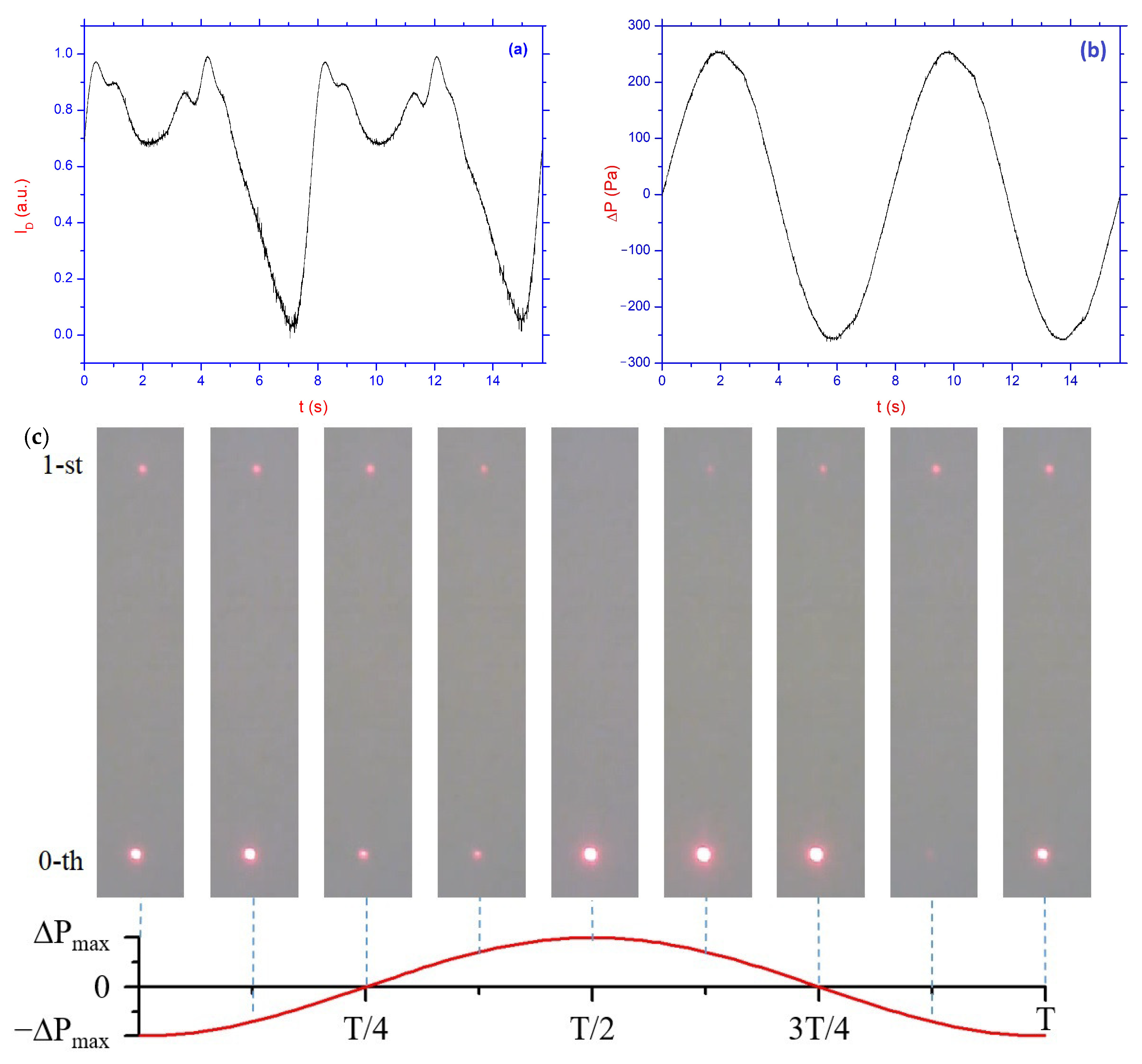
Figure 2a,b shows the time dependence of the normalized intensity
of the main maxima of diffracted light in the presence of the analyzer, as well as the corresponding pressure difference
applied to the LC layer. These measured values correspond to the LC cell with the relief height of 360 nm.
Figure 2c shows images of the 0th and 1st diffraction maxima when applying the corresponding pressure difference to the LC layer. The images were obtained for a cell with a relief height of 180 nm.
The asymmetric pattern of changes in the intensity of diffraction maxima in the corresponding compression and rarefaction phases can be explained by the sensitivity of the initial orientational planar–homeotropic structure realized in the experiments to the direction of flow. At the same time, the repetition of the intensity changes during the repetition of the whole pressure drop oscillation can be explained by the established mode of director reorientation. As can be seen in
Figure 2a,c, with the polarizer and analyzer crossed, there is a significant change in light intensity as the pressure gradient changes. This corresponds to the typical controlled birefringence for LC. Of particular interest are the changes in the intensity of diffracted light in the absence of an analyzer.
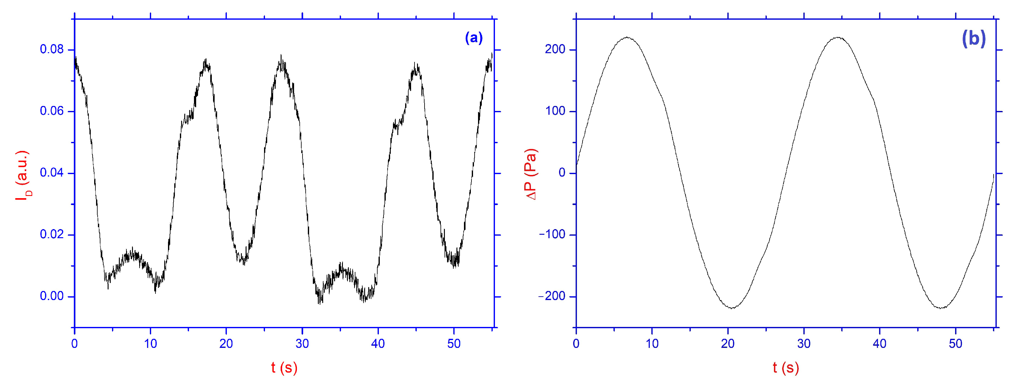
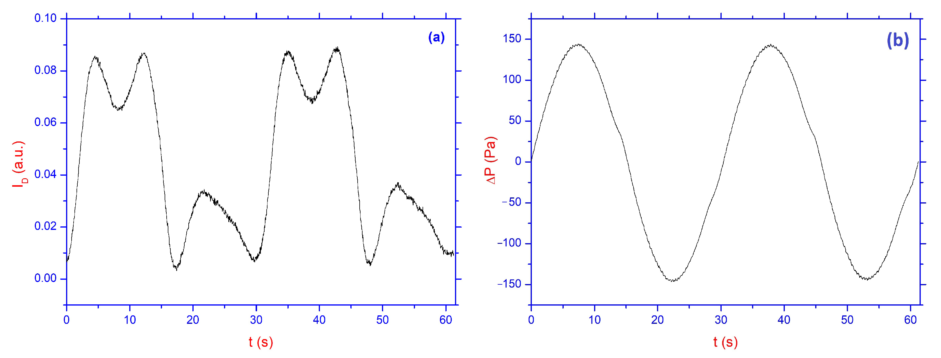
Typical time dependencies of the normalized intensity
of the main and first maxima of diffracted light in the absence of the analyzer, as well as time dependencies of the pressure difference
with an amplitude value from 0 to 200 Pa are shown in
Figure 3a and
Figure 4a, as well as in
Figure 3b and
Figure 4b, respectively. These measured values correspond to the LC cell with a relief height of 360 nm and 180 nm and a frequency of
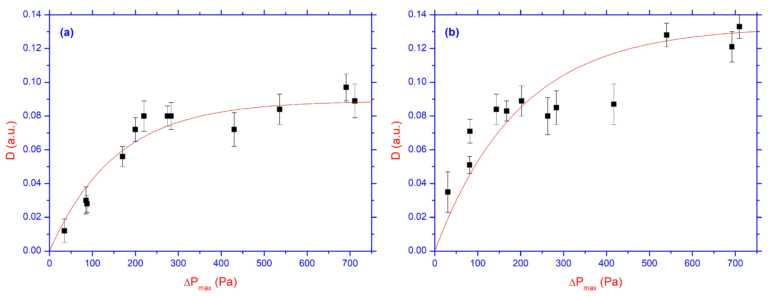
Hz. The quasi-steady flow approximation allows us to analyze all the obtained data, assuming that the maximum change in the intensity of polarized light depends mostly on the value of the maximum pressure difference.
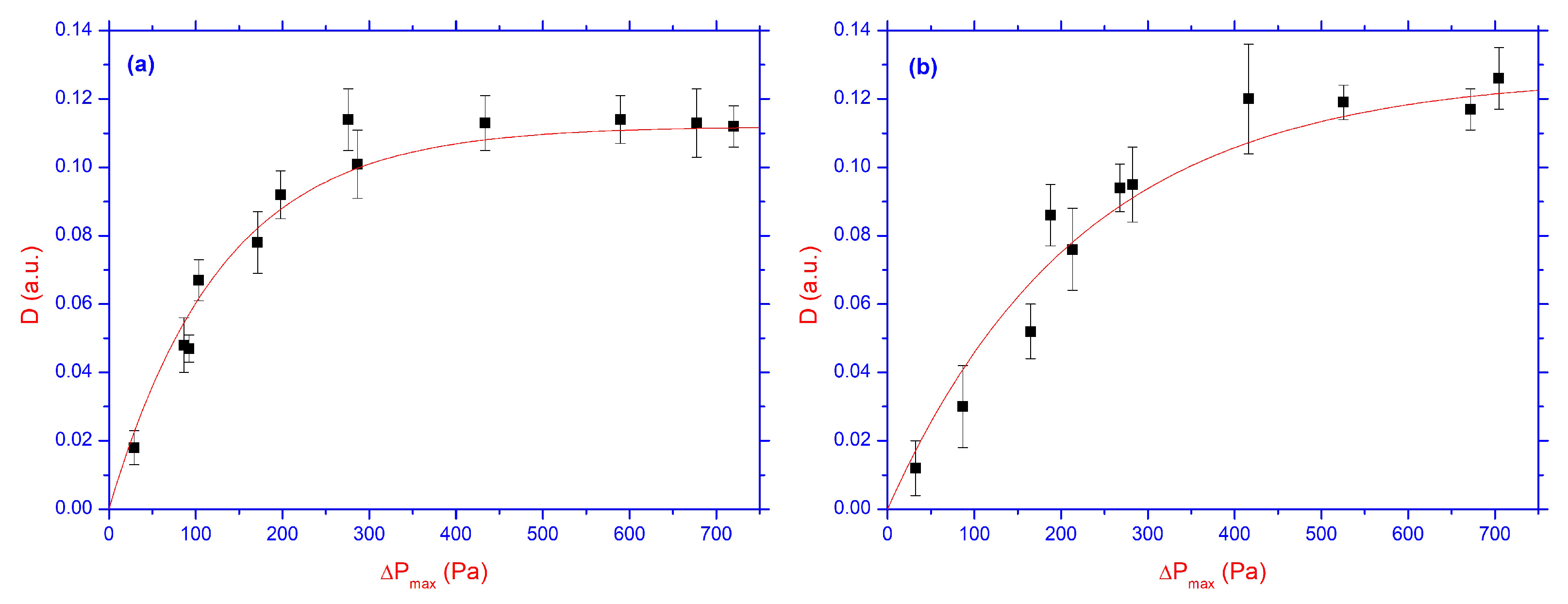
Figure 5 and
Figure 6 show the dependencies of the maximum change in the normalized intensity
of diffracted light on the amplitude of the pressure difference for the main (see
Figure 5a) and 1st maxima (see
Figure 5b), for the value of the relief height
nm, while in
Figure 6a,b, same as in
Figure 5a,b, but for
nm, respectively.
On average, the experiment with each value of the pressure drop amplitude was repeated from 3 to 7 times, which made it possible to analyze the deviations and approximate the obtained results. The solid lines in
Figure 5 and
Figure 6 described by exponential functions
, with
,
, and
,
,
, and
,
,
, and
,
,
, and
, respectively. Here, the number (1) corresponds to
Figure 5a, (2) to
Figure 5b, (3) to
Figure 6a, and (4) to
Figure 6b, respectively.
4. Discussion
As can be seen from
Figure 5 and
Figure 6, approximately the same (
) radiation modulation depth with saturation at 600–700 Pa is observed for both relief depths, as well as for the main and first diffraction maxima. Therefore, it can be assumed that the effect under consideration depends weakly on characteristics of the reliefs used in experiments and is largely associated with changes of director orientation in the region far from the PAZO surface. Our results also show that submicron relief with a depth of 180 and 360 nm and a period of 2 μm has a weak effect on diffracted light passing through the LC layer. This weak effect can be explained by analysis of the free energy density for the stressed state of the nematic phase, which is proportional to the square of the derivative of
as [
26]
where the surface relief can be approximately described by a sinusoidal wave
Here,
is the amplitude, while
is the period of the grooved microrelief. Further, for simplicity, let us assume that the director
belongs to the (
) plane, i.e.,
,
, and
, respectively.
Assuming that the director
is orthogonal to the wavelike surface, then it is not difficult to obtain a boundary condition for the
component of the director field
Then, the dependence of the distortion of the director field on the coordinates (
) can be written as
Substituting this expression into Equation (
5) and integrating the free energy density
over the half-space occupied by the nematic layer and by minimizing this functional, one can obtain the Euler–Lagrange equation for distortion
in the nematic film,
Taking into account the boundary condition Equation (
7), and the complete decaying of deformations in the nematic volume, when
, the solution of Equation (
9) has the form
where
is the characteristic depth of deformation decaying. Since the value of undulating relief
m, the depth of penetration of distortion in the case of nematic phase is
m, and the penetration depth does not depend on the amplitude of
.
The results obtained can be explained by taking into account the fact that the presented diffraction grating belongs to the phase gratings. Thus, changing the orientation of the LC layer under the action of the flow led to a change in the phase delay between ordinary and extraordinary rays passing through areas with minimum and maximum thicknesses of the liquid crystal layer. This is due to the strong dependence of the sensitivity of the orientation structure of the planar–homeotropic cell on the local thickness of the LC layer, established earlier in experiments with flat surfaces [
16]. Thus, under the influence of the flow, the phase delay changes both in the area of peaks and in the area of bottoms on the relief, but the magnitude of these changes is different. Estimates based on the data presented in [
16] show that for an extraordinary beam, the dependence of the phase change of the extraordinary wave caused by the flow is about 5–6% with a change in thickness corresponding to the depth of relief. For a phase diffraction grating, this also leads to a change in intensity of about 5–6% [
27].
In addition to the above-mentioned mechanism, there may be a different effect of the flow on the azimuthal director rotation angle at the bottoms and on the tops of the relief. Thus, light scattering may occur due to the non-uniformity of the refractive index in the neighboring areas of the LC layer. It is confirmed by the flow-induced light scattering observed in experiments.
The second mechanism responsible for changing the intensity of transmitted light is scattering by hydrodynamic instabilities in the LC layer and instability of the orientation of the LC on the PAZO layer. The occurrence of hydrodynamic instabilities in the LC layer is described using two dimensionless parameters, the Reynolds (Re) and the Eriksen (Er) numbers. Estimates show that the flow velocities at which LC-specific instabilities, described by the Eriksen number, occur are six orders of magnitude lower than the velocities at which the turbulent flow occurs. In our LC cells, the flow direction coincides with the direction of the relief grooves (
Figure 1b). However, in the absence of flow, the surface orientation of the NLC on the exposed area of the PAZO layer deviates from the relief grooves’ direction, and the initial plane of the director distribution forms an angle
with the flow plane. Thus, when a pressure difference is applied to the LC layer, a flow-induced torque is generated, which causes the director to rotate towards the direction of the flow. Theoretical estimates of the occurrence of this type of instability were made for a geometry in which, over the entire thickness of the LC layer, the director of NLC is perpendicular to the flow velocity and flow velocity gradient (
). The threshold pressure gradient at which such instabilities arise is determined by the critical value of the Eriksen number [
28]:
where
is the value of a pressure gradient,
L is the length of the LC channel,
and
are the Leslie coefficients,
and
are the splay and twist Frank`s elastic constants,
is the shear viscosity coefficient (Miesowicz viscosity), corresponding to the orientation of the NLC director perpendicular to the flow velocity and flow velocity gradient. Despite the significant difference between theoretical geometry and the geometry implemented in our case, it may be of interest to compare the theoretical estimate with the experimental results. In particular, the critical value of the Ericksen number corresponding to the threshold of the above-mentioned instability at the initial planar orientation normal to the direction of flow is defined as
[
29]. Using this value and well-known material parameter values for 5CB NLC (
Pa s,
Pa s,
pN,
pN,
Pa s [
30,
31]), we can determine the critical value of the pressure difference
kPa, which is almost 10 times greater than the maximum values of
used in the experiment. It indicates the absence of threshold phenomena in the experimentally realized geometry. Nevertheless, the influence of shear flow on the bulk structure of an LC director initially stabilized by a magnetic field at an angle of
has also been previously studied analytically (for example, [
32]). The modes of occurrence of nonequilibrium fluctuations in such a geometry were demonstrated, which may indicate the occurrence of a tumbling instability in this type of geometry.
The same conclusion of absence of threshold phenomena can be made regarding the instability caused by the flow (escape of the director from the flow plane), with an initially homeotropic orientation. Indeed, as mentioned above, the initial plane of the orientation distribution differs from the flow plane. This should stimulate the exit of the director from the flow plane caused by the flow, which can lead to a decrease, possibly down to zero, in the value of the threshold pressure gradient. Indeed, the previously obtained results of the study of such instability in the homeotropic layer of NLC MBBA led to the following expression for the critical amplitude of the pressure drop
applied to the LC channel length
mm as a function of the layer’s thickness (
m) [
16]:
where
m,
(for MBBA),
Pa. We can obtain an approximate estimate of the critical pressure drop
kPa corresponding to the escape of the director from the flow plane at the thickness of the LC layer and the length of the channel used in our experiment. Obviously, the correct explanation of the experimental results will demand the numerical solutions of the hydrodynamic equations of LC, taking into account the flow-induced changes in both the polar and azimuthal angles of the director. Previously, the flow-induced deformations of the initial planar–homeotropic orientation of the director of the nematic phase were considered only for the case of polar angle inclinations [
33,
34].
Orientation instabilities of the LC phase on the PAZO layer can occur due to the formation of a photoinduced relief (small deviations of incident interfering rays on the PAZO layer, the difference in the intensity of the interfering beams), as shown in
Figure 7.
This Figure shows microscopic polarizing images of a planar–homeotropic LC layer in a cell (the scheme of which is shown in
Figure 1b), when the oscillating pressure difference is applied. The images show that the orientation structure at the bottom part of the pictures is non-uniform, and at
Pa this non-uniformity persists throughout the entire period of pressure oscillation. At
kPa at time
–
, the action of the flow suppresses the above-mentioned non-uniformities, and the orientation structure looks uniform. Here,
s is the oscillating period. However, this behavior is not observed at the opposite phase of oscillation. This indicates that the flow direction has a different effect on the director’s reorientation in the upper and lower parts of the LC channel. This behavior may be due to the above-mentioned non-uniformity of the LC alignment at the different spots in the illuminated area, where the interference of incident rays could be disrupted, resulting in the formation of a relief with different characteristics and properties. As was shown, for example, in [
35], small deviations in the boundary orientation of the director can significantly change the profile of the LC flow, which can also affect the change in the intensity of the transmitted light.

