Article

Outcome of Hall Current and Mechanical Load on a Fiber-Reinforced Thermoelastic Medium per the Hypothesis of One Thermal Relaxation Time

by
Samia M. Said
1,
Emad K. Jaradat
2,
Hanan S. Gafel
3 and
Sayed M. Abo-Dahab
4,*
1
Department of Mathematics, Faculty of Science, Zagazig University, Zagazig 44519, Egypt
2
Department of Physics, Faculty of Science, Imam Mohammad Ibn Saud Islamic University (IMSIU), Riyadh 11623, Saudi Arabia
3
Department of Mathematics and Statistics, College of Science, Taif University, P.O. Box 11099, Taif 21944, Saudi Arabia
4
Mathematics Department, Faculty of Science, South Valley University, Qena 83523, Egypt
*
Author to whom correspondence should be addressed.
Crystals 2025, 15(11), 924; https://doi.org/10.3390/cryst15110924
Submission received: 11 September 2025 / Revised: 21 October 2025 / Accepted: 21 October 2025 / Published: 27 October 2025
(This article belongs to the Special Issue Mechanical Properties and Structure of Metal Materials)

Abstract

The current study shows the propagation of waves in a fiber-reinforced thermoelastic medium with an inclined load under the effect of Hall current and gravitational force. The problem is analyzed using the Lord–Schulman hypothesis of one thermal relaxation time. A normal mode method is utilized to acquire the analytical result for any boundary condition. Several investigations have been adapted into figures to display the impacts of the gravity field, Hall current, inclined load, and the empirical solid constant on all physical quantities. A comparison is made with the obtained results to indicate the strong impact of the external parameters acting on the phenomenon of mechanical load on the fiber-reinforcement thermoelastic medium.

1. Introduction

Lately, great attention has been given to the hypothesis of thermoelasticity due to its useful facets in various fields, particularly engineering, construction, geology, biology, geophysics, acoustics, physics, plasma, etc. Duhamel [1] and Neumann [2] introduced an uncoupled theory of thermoelasticity that has two defects. The first defect is that it ignores the effect of elastic changes on temperature. The second defect is that its parabolic heat equation predicts an infinite speed of heat propagation, which contradicts physical reality. Biot [3] introduced the coupled theory of thermoelasticity to improve the shortcomings of the uncoupled hypothesis, proposing that mechanical deformation has no effect on temperature. Lord and Shulman [4] presented the (L-S) hypothesis, which determines the bounded velocity of motion owing to a thermal field exploitation of a single relaxation time. A domain-of-influence proposition for an initial-boundary-value problem of thermoelasticity with a single relaxation time, as projected by Lord and Schulman, was created by Ignaczak and Bialy [5]. Thermoelasticity, with a single relaxation time for each problem, excluding heat sources, was formed into a matrix to exploit the state space and Laplace transforms by Sherief [6]. He and Cao [7] examined the magneto-thermoelastic properties of a thin, slim strip placed in a magnetic field and affected by a moving plane of heat via the (L-S) theory. Abo-Dahab and Abbas [8] analyzed the imminent phenomena in the magneto-thermoelastic model via the (L-S) theory. The (L-S) hypothesis has recently been cited in many studies across a broad scope of themes [9,10,11,12,13].
Recent works have analyzed the physical properties of semiconductor charge performance by creating new measurement methods that exploit the Hall effect. In the semiconductor world, Edwin Hall [14] found that when a magnetic field orthogonal to the path of the incumbent was practical, the regimen and denseness of electrons were aberrant. The Hall current that was adapted by Cowling [15] states that when the attitude of the magnetic field is sufficiently strong, Ohm’s law has to be adapted to exclude Hall currents. Salem [16] displayed the constant laminar flow rate of a power-law fluid in the context of an axial consistent magnetic field in the neighborhood of a perpetually rotating infinite disk, creating a Hall current as a result. Reddy and Rao [17] deliberated on the impacts of emission and thermal diffusion on an unsteady magneto-hydrodynamic (MHD) escaped activity flow of a viscous fluid with the Hall current and a heat source. Zakaria [18] displayed a micropolar thermoelastic solid affected by a magnetic field, taking into consideration the consequences of a Hall current capable of ramp-type heating. The impact of the Hall current on various thermoelastic media is constituted in many studies and articles on a wide range of themes [19,20,21,22].
Thermal stresses in a medium with temperature-dependent properties (TDP) were discussed broadly by Noda [23]. Roy Choudhuri and Chatterjee [24] applied the TDP theory via the Green and Lindsay hypothesis. Temperature-dependent measurement of Young’s modulus was accomplished for the first time on a black and crystalline bulk medium of chemical vapor deposited in diamond by Szuecs et al. [25]. Aouadi [26] established a hypothesis to create a mathematical statement for a thermo-piezoelectricity medium with the TDP hypothesis. Othman and Kumar [27] created a magneto-thermoelastic perfectly conducting medium via the TDP hypothesis. Abbas [28] demonstrated a three-dimensional problem by applying the Green-Naghdi hypothesis subordinate to the TDP hypothesis. The TDP theory has recently been included in many studies and articles over a broad scope of subject matter [29,30,31,32,33].
The present problem concerns a fiber-reinforced thermoelastic solid in the context of a consistent, powerful magnetic field that acts in the y-direction, interpreted using the Hall current. This brand-new problem is analyzed via the Lord–Schulman framework. The partial differential equations are created and precisely resolved using normal mode analysis. Comparisons are made between the physical fields for various magnitudes of gravity field, Hall current, and inclined load as well as the empirical solid constant.

2. Description of the Problem and the Fundamental Relations

The governing equations of a homogeneous anisotropic fiber-reinforced thermoelastic medium under the influence of a gravity field and Hall current via the Lord–Schulman hypothesis, as described by Belfield et al. [34] and Zakaria [18] are as follows:
(i)
The constitutive relations
σ i j = λ e k k δ i j + 2 μ T e i j + α ( a k a m e k m δ i j + a i a j e k k ) + 2 μ L μ T ( a i a k e k j + a j a k e k i ) + β a i a j a k a m e k m γ θ δ i j .
(ii)
The equations of motion
ρ 2 u i t 2 = σ j i , j + μ 0 ( J ¯ x H ¯ ) i + F i
where F 1 = ρ g w x ,   F 2 = 0 ,   F 3 = ρ g u x ,   are the components of force due to the existence of the gravitational field and μ 0   ( J ¯ x H ¯ ) i is the Lorentz force due to the existence of the magnetic field, as in Said [30].
(iii)
The equation of heat conduction after Lord and Shulman [4]
K   2 θ = 1 + τ 0 t   ρ C E θ t + γ   T 0   e t
(iv)
Hall current as follows Zakaria [18]
J ¯   = σ 0 1 + m 2   E ¯ + μ 0 ( u ¯ t H ¯ ) μ 0 e n e ( J ¯ H ¯ ) .
We assume that E = 0 , and Ohm’s law J 2 = 0 , for every place in the medium, and we obtain
J 1 =   σ 0 μ 0 H 0 ( 1 + m 2 ) m u t w t ,   J 2 =   0 ,   J 3 =   σ 0 μ 0 H 0 ( 1 + m 2 ) u t   + m w t .
We assume that as in Abbas [28]:
μ = μ 1 f ( T ) ,   λ = λ 1   f ( T ) ,   α =   α 1 f ( T ) ,   μ T =   μ T 1 f ( T ) ,   μ L =   μ L 1 f ( T ) ,   β = β 1 f ( T ) ,
where f ( T ) = ( 1 α * T 0 ) , the case of the temperature-independent modulus of elasticity if α * = 0 .
Equation (2) takes the following form:
ρ 2 u t 2 =   π 1 2 u x 2 + π 2 2 w x z + π 3 2 u z 2 γ θ x σ 0 μ 0 2 H 0 2 1 + m 2 u t σ 0 μ 0 2 H 0 2 1 + m 2 w t + ρ g w x ,
ρ 2 w t 2 = π 3 2 w x 2 + π 2 2 u x z + π 4 2 w z 2 γ θ z + σ 0 μ 0 2 H 0 2 1 + m 2 u t σ 0 μ 0 2 H 0 2 1 + m 2 w t ρ g u x ,
where π 1 = λ + 4 μ L 2 μ T + 2 α + β ,   π 2 = λ + μ L + α ,   π 3 = μ L ,   π 4 = λ + 2 μ T .
It is convenient to present the following non-dimensional quantities:
( x , z , u , w ) = 1 l 0 ( x , z , u , w ) ,   ( t , τ 0 ) = c 0 l 0 ( t , τ 0 ) ,   θ = γ θ λ + 2 μ T ,   g = l 0 c 0 2 g ,   σ i j = σ i j μ T ,
l 0 = K ρ C E T 0 ,   c 0 = λ + 2 μ T ρ .
The governing equations declared above have the leading form when exploiting the non-dimensional variants recorded above that are introduced in Equation (9).
2 u t 2 = r 1 2 u x 2 + r 2 2 w x z + r 3 2 u z 2 θ x π 5 u t π 6 w t + g w x ,
2 w t 2 = r 3 2 w x 2 + r 2 2 u x z + r 4 2 w z 2 θ z + π 6 u t π 5 w t g u x ,
2 θ = d 1 1 + τ 0 t θ t + d 2 1 + τ 0 t e t ,
where ( r 1 , r 2 , r 3 , r 4 ) = ( π 1 ρ c 0 2 , π 2 ρ c 0 2 , π 3 ρ c 0 2 , π 4 ρ c 0 2 ) ,   π 5 = σ 0 μ 0 2 H 0 2 l 0 2 ρ c 0 ( 1 + m 2 ) ,   π 6 = m π 5 ,   d 1 = ρ C E c 0 l 0 K ,   d 2 = γ 2 T 0 c 0 l 0 K ( λ + 2 μ T ) .

3. The Analytical Method

The following form can be utilized to break up the result of the physical variable subordinate thinking in the status of the normal mode method:
u , w , θ , σ i j ( x , z , t ) = u * , w * , θ * , σ * i j ( z ) exp i b x s t .
Using Equations (10)–(13), we obtain
D 2 u * = N 1 u * N 2 w * + N 3 θ * + N 4 D w * ,
D 2 w * = N 5 u * + N 6 w * + N 7 D u * + N 8 θ * ,
D 2 θ * = N 9 u * + N 10 θ * N 11 D w * ,
where
N 1 = s 2 + b 2 r 1 π 5 s r 3 ,   N 2 = π 6 s + i b g r 3 ,   N 3 = i b r 3 ,   N 4 = i b r 2 r 3 ,   N 5 = π 6 s + i b g r 4 ,   N 6 = s 2 + b 2 r 3 π 5 s r 4 ,   N 7 = i b r 2 r 4 ,   N 8 = 1 r 4 ,   N 9 = i b d 2 s ( 1 τ 0 s ) ,   N 10 = b 2 d 1 s ( 1 τ 0 s ) ,   N 11 = d 2 s ( 1 τ 0 s ) ,   D = d d z .
According to Said [35], rewrite Equations (14)–(16) as a vector-matrix differential equation.
D G ( z ) = A G ( z ) ,   G ( z ) = [ u * , w * , θ * , D u * , D w * , D θ * ] T ,
where
A = 0 0 0 1 0 0 0 0 0 0 1 0 0 0 0 0 0 1 N 1 N 2 N 3 0 N 4 0 N 5 N 6 0 N 7 0 N 8 N 9 0 N 10 0 N 11 0 .

4. The Resolution of the Differential Equation via a Vector Matrix

The characteristic equation of a matrix A is
K 6 C 1 K 4 + C 2 K 2 C 3 = 0 ,
where C 1 = N 1 + N 6 + N 10 + N 4 N 7 N 8 N 11 ,     C 2 = N 1 N 6 + N 2 N 5 + N 1 N 10 N 3 N 9 + N 6 N 10 N 1 N 8 N 11 + N 3 N 7 N 11 + N 4 N 7 N 10 N 4 N 8 N 9 , C 3 = N 1 N 6 N 10 + N 2 N 5 N 10 N 3 N 6 N 9 ,
Let K 1 2 , K 2 2 and K 3 2 be the roots of Equation (19) with positive real parts. For the eigenvalue
K of matrix A , the right eigenvector χ = ( x 1 , x 2 , x 3 , x 4 , x 5 , x 6 ) T is
x 1 = N 8 K ( N 4 K N 2 ) + N 3 ( K 2 N 6 )   ,     x 2 = N 8 K ( K 2 N 1 ) + N 3 ( N 5 + N 7 K ) ,   x 3 = N 9 ( N 4 K N 2 ) N 11 K ( K 2 N 1 )   ,       x 4 = K x 1   ,       x 5 = K x 2   ,       x 6 = K x 3 .
The following notations: χ 1 = [ χ ] K = K 1 ,   χ 2 = [ χ ] K = K 1 ,   χ 3 = [ χ ] K = K 2 ,   χ 4 = [ χ ] K = K 2 ,   χ 5 = [ χ ] K = K 3 ,   χ 6 = [ χ ] K = K 3 , are used to find the eigenvector χ j ( j = 1 , 2 , ... , 6 ) related to the eigenvalue ± K j ( j = 1 , 2 , 3 ) .
The result to Equation (17) is forced as z
u * ( z ) = n = 1 3 x 1 n Γ n e k n z ,   u ( z ) = n = 1 3 x 1 n Γ n e ( i b x s t k n z ) ,
w * ( z ) = n = 1 3 x 2 n Γ n e k n z ,   w ( z ) = n = 1 3 x 2 n Γ n e ( i b x s t k n z ) ,
θ * ( z ) = n = 1 3 x 3 n Γ n e k n z ,   θ ( z ) = n = 1 3 x 3 n Γ n e ( i b x s t k n z ) ,
where Γ n   ( n = 1 , 2 , 3 ) are parameters, x 1 n = [ x 1 ] K = k n ,   x 2 n = [ x 2 ] K = k n ,   x 3 n = [ x 3 ] K = k n .
Using the preceding equations, we acquire
σ z z * ( z ) = n = 1 3 x 4 n Γ n e k n z ,   σ z z ( z ) = n = 1 3 x 4 n Γ n e ( i b x s t k n z ) ,
σ x z * ( z ) = n = 1 3 x 5 n Γ n e k n z ,   σ x z ( z ) = n = 1 3 x 5 n Γ n e ( i b x s t k n z ) ,
where x 4 n = i b π 7 x 1 n π 4 K n x 2 n ( λ + 2 μ T ) x 4 n μ T ,   x 5 n = i b π 2 x 2 n π 3 K n x 1 n μ T .

5. Boundary Conditions

In physical problems, we should neglect the positive exponents that are unbounded at infinity. In order to determine the parameters Γ n ( n = 1 , 2 , 3 ) , we have to consider the boundary conditions at z = 0 as follows:
(a)
The condition of the thermal boundary is that the surface corresponds to an isothermal boundary
θ = 0 .
(b)
The condition of the mechanical boundary is that the surface corresponds to an inclined load
σ z z = f 0 cos ( φ 0 ) ,   σ x z = f 0 sin ( φ 0 ) ,
where f 0 is a constant and φ 0 is the angle of the inclined load.
By inserting Equations (23)–(25) into Equations (26) and (27), we have
n = 1 3 x 3 n Γ n = 0 , n = 1 3 x 4 n Γ n = f 0 cos ( φ 0 ) , n = 1 3 x 5 n Γ n = f 0 sin ( φ 0 ) .
The inverse matrix method is used to solve Equation (28) as follows:
Γ 1 Γ 2 Γ 3 = x 31 x 32 x 33 x 41 x 42 x 43 x 51 x 43 x 43 1 0 f 0 cos ( φ 0 ) f 0 sin ( φ 0 ) .

6. Results and Numerical Discussion

We show numerical results for physical constants to illustrate and validate the accuracy of the theoretical calculations created in the preceding sections via the L-S model, after Othman et al. [36].
λ 1 = 1.76 × 10 9   N · m 2 ,   μ T 1 = 2.86 × 10 9   N · m 2 ,   μ L 1 = 7.86 × 10 9   N · m 2 ,   T 0 = 293   K ,   ρ = 7800   kg · m 3 , s = s 0 + i ξ ,   s 0 = 1.9   s 1 ,   ξ = 0.7   s 1 ,   C E = 383   J · kg 1 · K 1 ,   β 1 = 2 × 10 9   N · m 2 ,   K = 386   w · m 1 · K 1 , α t = 1.78 × 10 6   K 1 ,   μ 1 = 3.86 × 10 9   N · m 2 ,   α 1 = 1.78 × 10 9   N · m 2 ,   μ 0 = 1.5   H · m 1 ,   σ 0 = 4.36 × 10 6 , b = 0.02 ,   τ 0 = 0.3   s ,   f 0 = 0.9 ,   H 0 = 1000   A · m 1 .
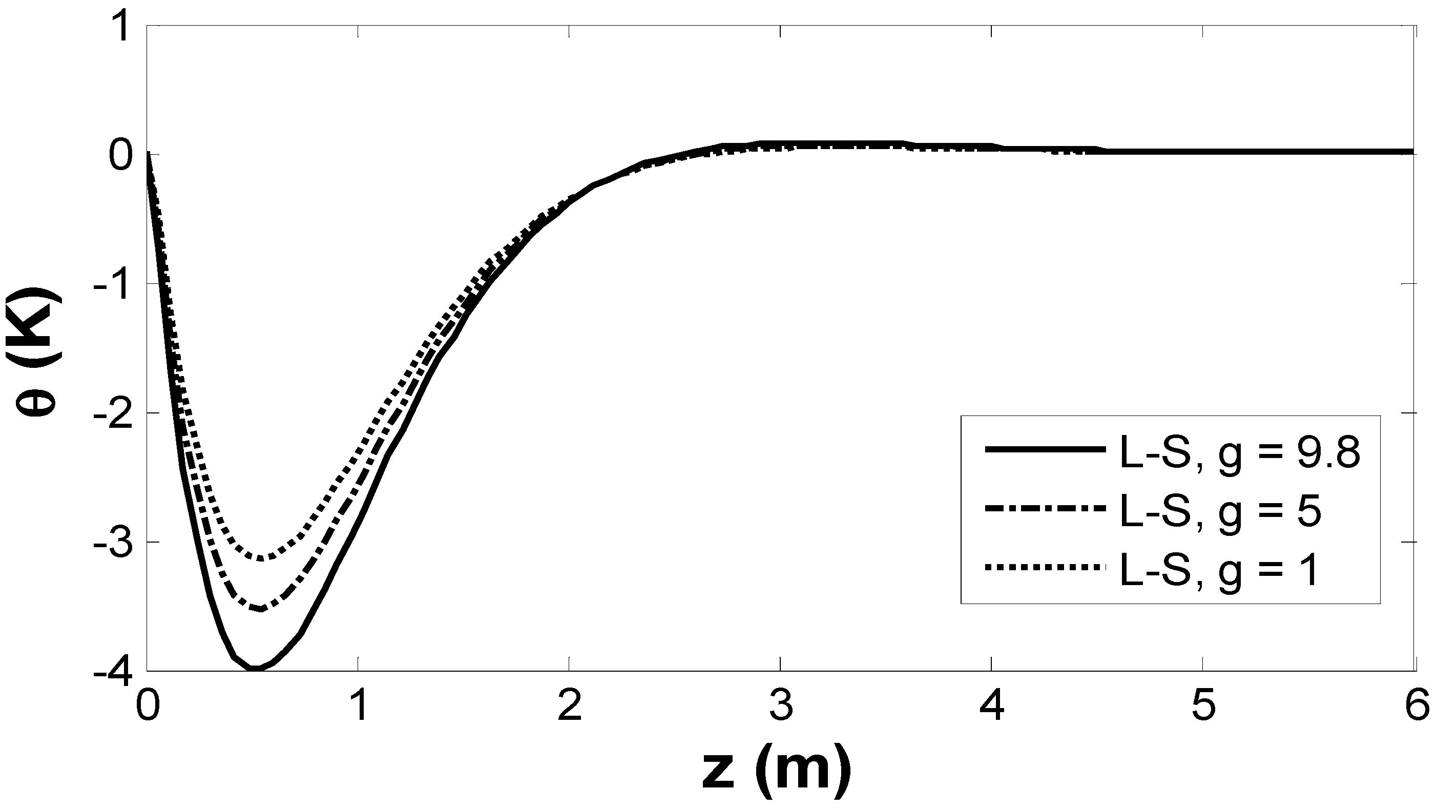
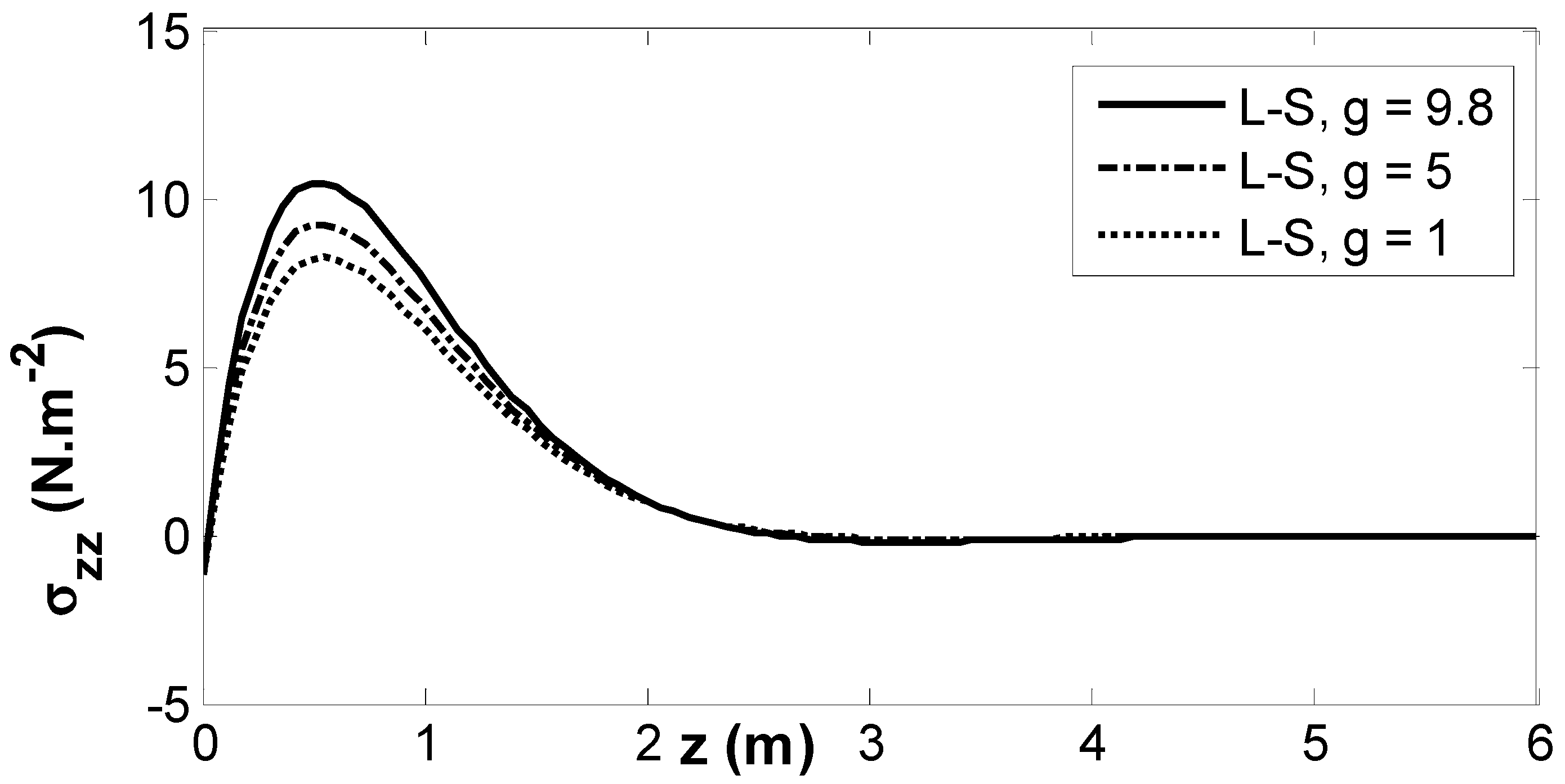
We calculate the numerical magnitudes of displacement, stresses, and temperature at t = 0.2   s ,   x = 1.5   m . The results are given in Figure 1, Figure 2, Figure 3, Figure 4, Figure 5, Figure 6, Figure 7, Figure 8, Figure 9, Figure 10, Figure 11, Figure 12, Figure 13, Figure 14, Figure 15 and Figure 16. Figure 1, Figure 2 and Figure 3 include a comparison via the L-S hypothesis, showing the behavior of these factors under different magnitudes of the gravity field ( g ) .  Figure 1 presents the displacement w through the L-S theory across the z -axis. For various magnitudes of the gravity field, w begins with a increase, and then a drop-off. The gain in gravity causes an increase in w .  Figure 2 exemplifies the dispersion of temperature θ for various magnitudes of the gravity field. The temperature θ matches to the boundary conditions, being an occurrence with a zero magnitude. It is illustrated that θ decreases to encompass a marginal value, then increases, and after that approaches a zero value as the distance x 6 . The increase in the gravity field causes a decrease in θ .  Figure 3 exemplifies the alteration of σ z z according to the L-S model under several values of the gravity field. σ z z corresponds to the boundary conditions, occurrences with a negative magnitude, rises over the specific range of 0 x 1 , then decreases, and finally becomes zero at x 6 . The increase in the gravity field drives the increasing of σ z z .
Figure 4, Figure 5 and Figure 6 include a comparison according to the L-S model, showing the behaviors of the different factors under various magnitudes of Hall current. Figure 4 presents w as a function of z . For different magnitudes of Hall current, w begins with an increase, then decreases, and finally becomes zero at x 6 . The increase in the Hall parameter causes an increase in w .  Figure 5 expands the dispersion of temperature θ according to the L-S model for various magnitudes of Hall current. It is discovered that θ bends to approach a minimum value, then increases, and after that drops to zero when the distance x 6 . The increase in the Hall parameter drives the decrease in θ .  Figure 6 presents the modification of σ z z according to the L-S model under various values of Hall parameter. σ z z adheres to the boundary conditions, first with a negative magnitude, then rises over the specific range of 0 x 1 to approach its peak value, then decreases, and eventually reaches zero at x 6 . The increase in the Hall parameter grounds the increase in σ z z .
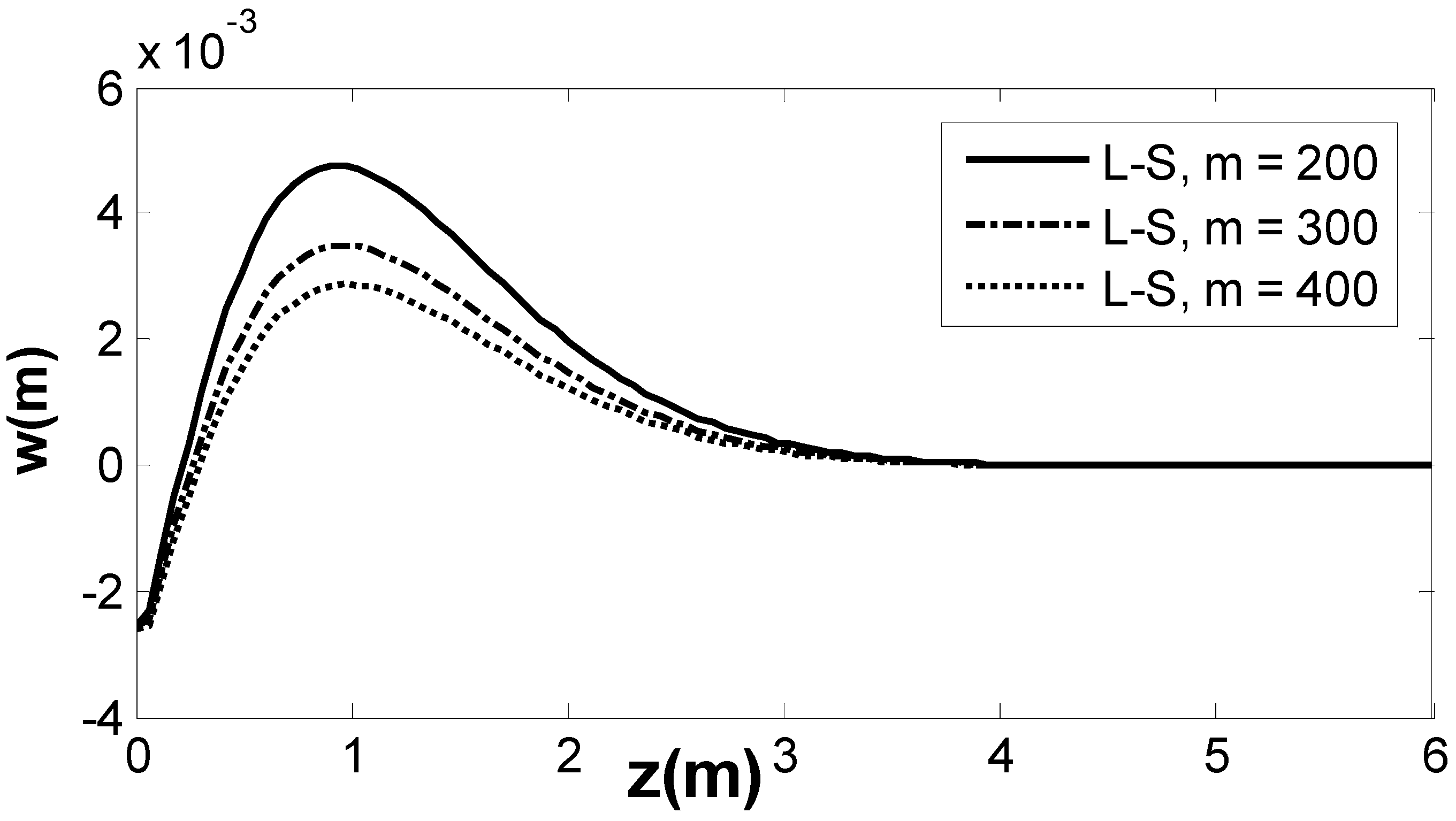
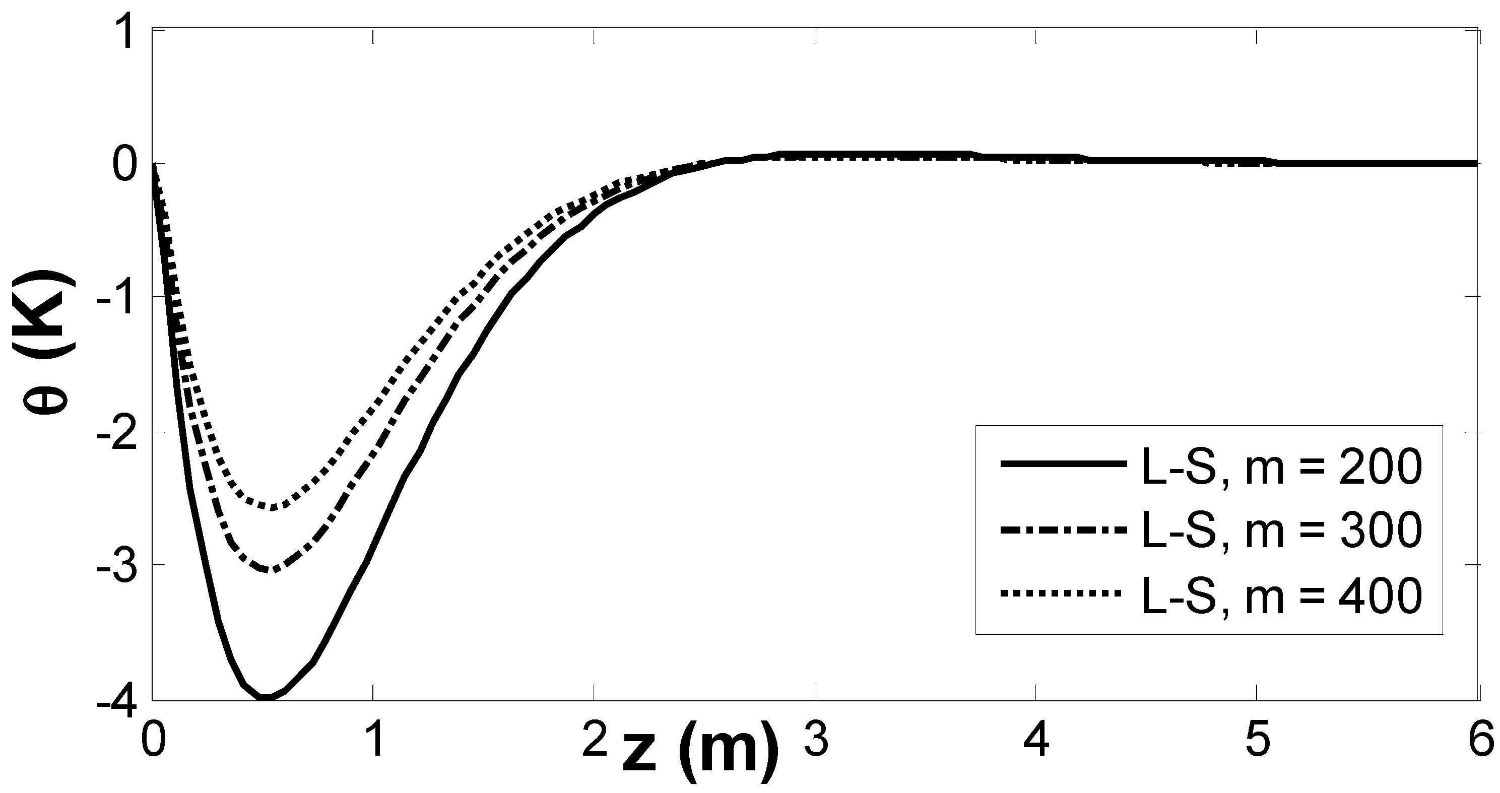
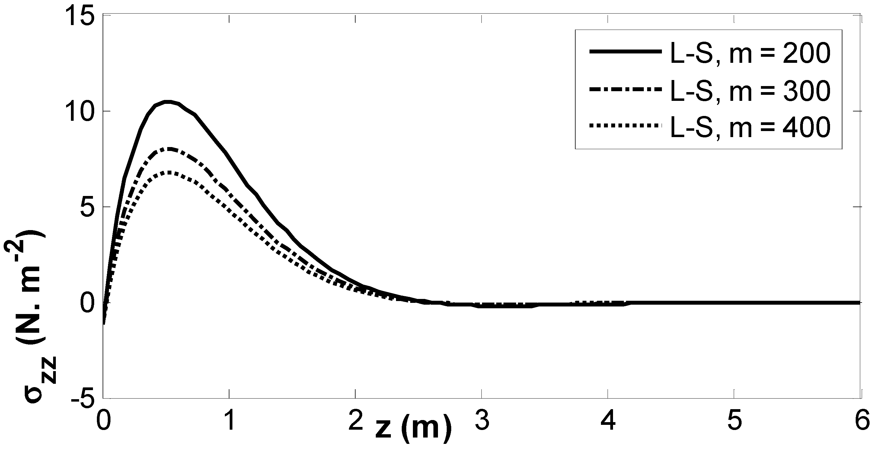
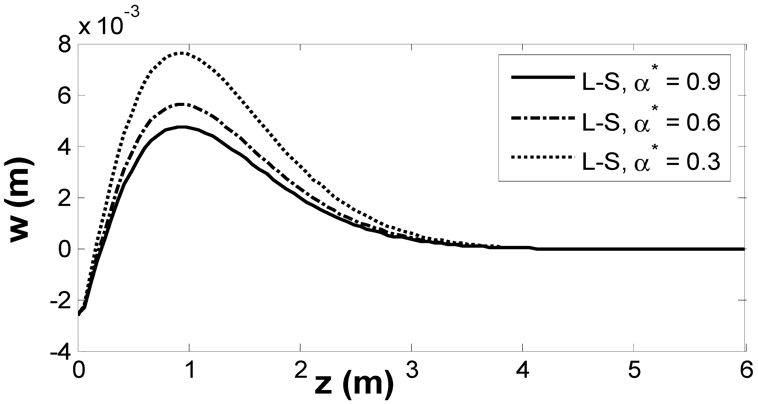
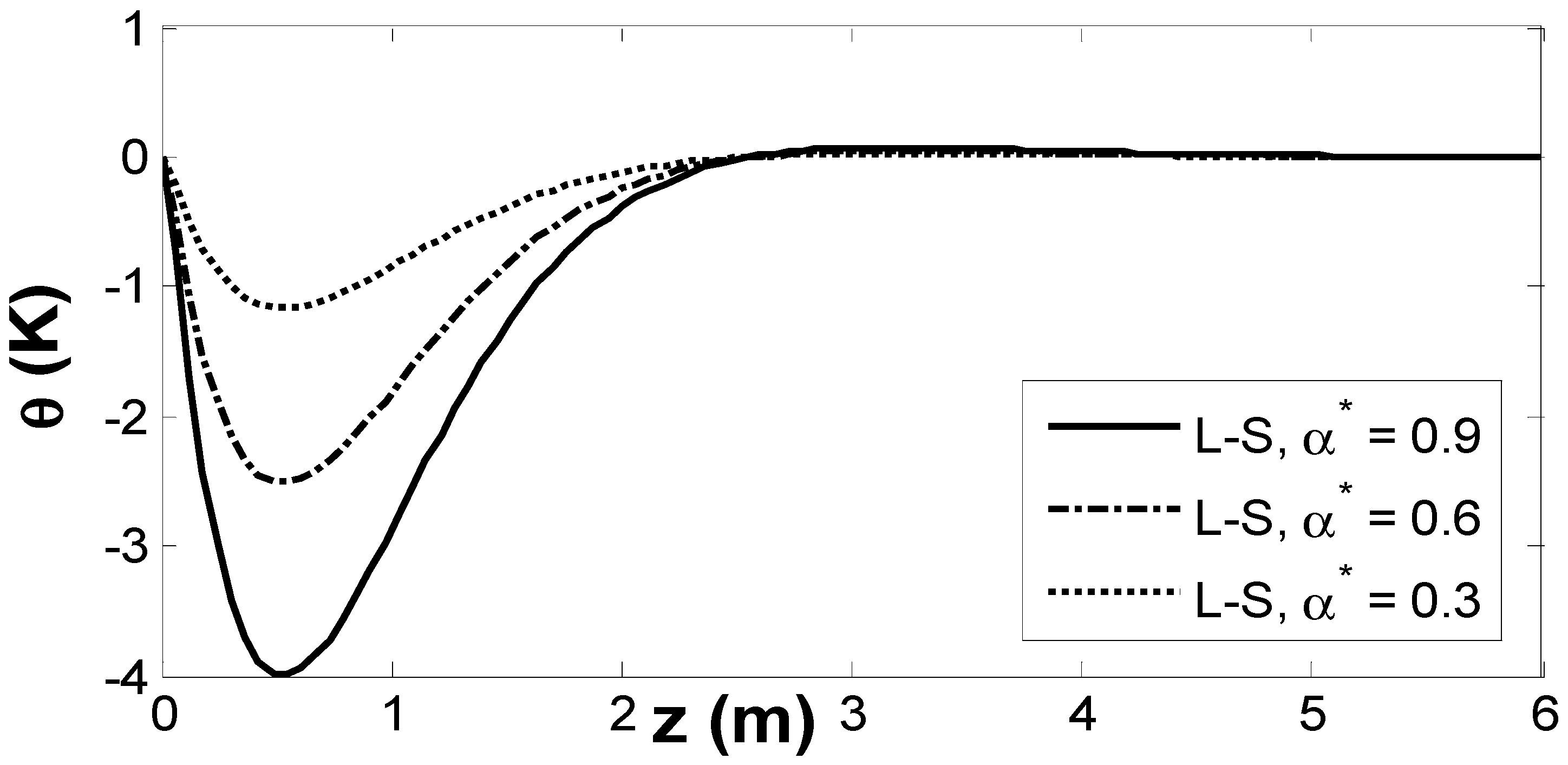
Figure 7, Figure 8 and Figure 9 include a comparison according to the L-S model, showing the behavior of different factors under various magnitudes of the empirical solid constant. Figure 7 demonstrates the fluctuation of w as a function of z . For various magnitudes of the empirical solid constant, w starts with an increase to approach a maximum magnitude, then decreases, and finally approaches zero at x 6 . The increase in the empirical solid constant causes the decrease in w .  Figure 8 displays the dispersion of temperature θ according to the L-S model for various magnitudes of the empirical solid constant. θ decreases to reach a minimum magnitude, then increases, and after that converges to zero as the distance x 6 . The increase in the empirical solid constant causes the diminishing of θ .  Figure 9 shows the fluctuation of σ z z according to the L-S model under different magnitudes of the empirical solid constant. σ z z starts out with a negative magnitude, rises over the specific range of of 0 x 1 to reach a maximum magnitude, then decreases, and finally becomes zero at x 6 . The increase in the empirical solid constant causes the increase in σ z z .
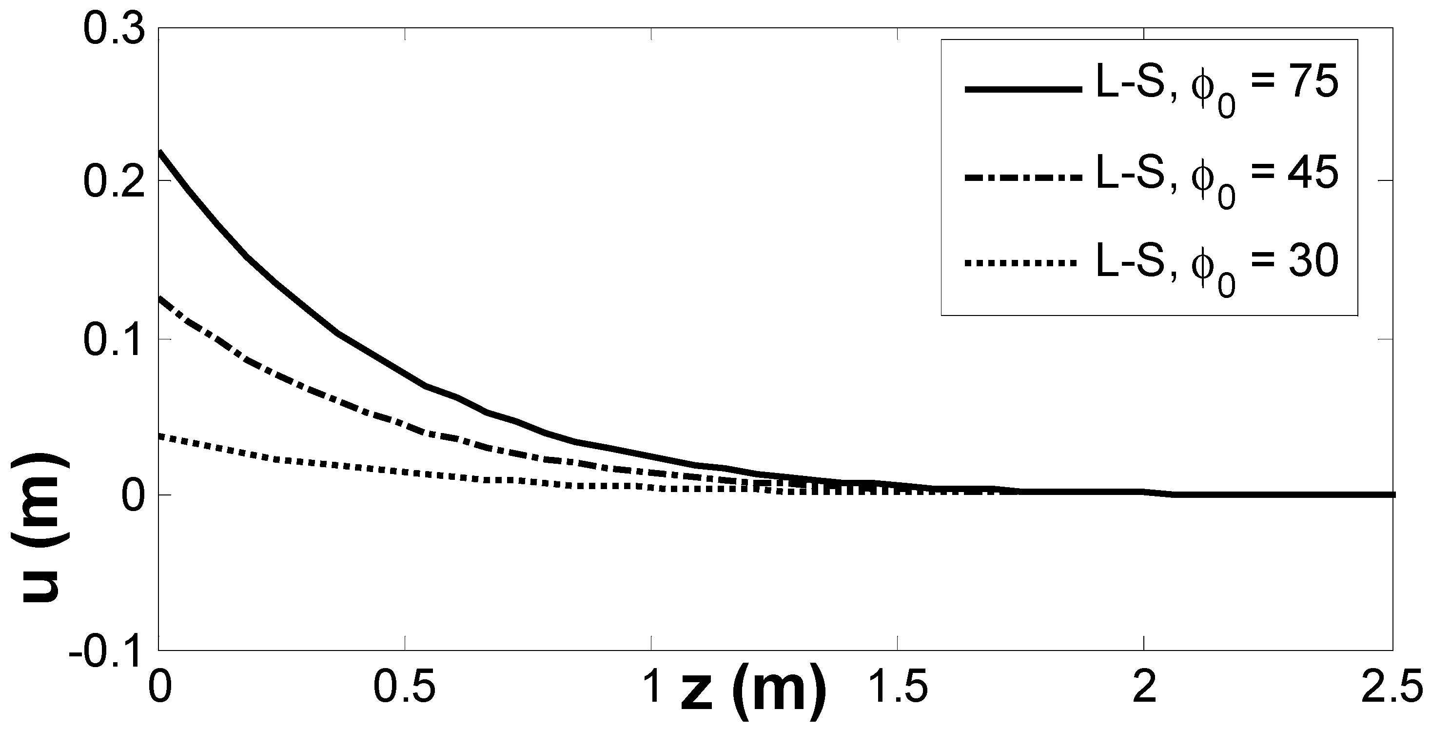
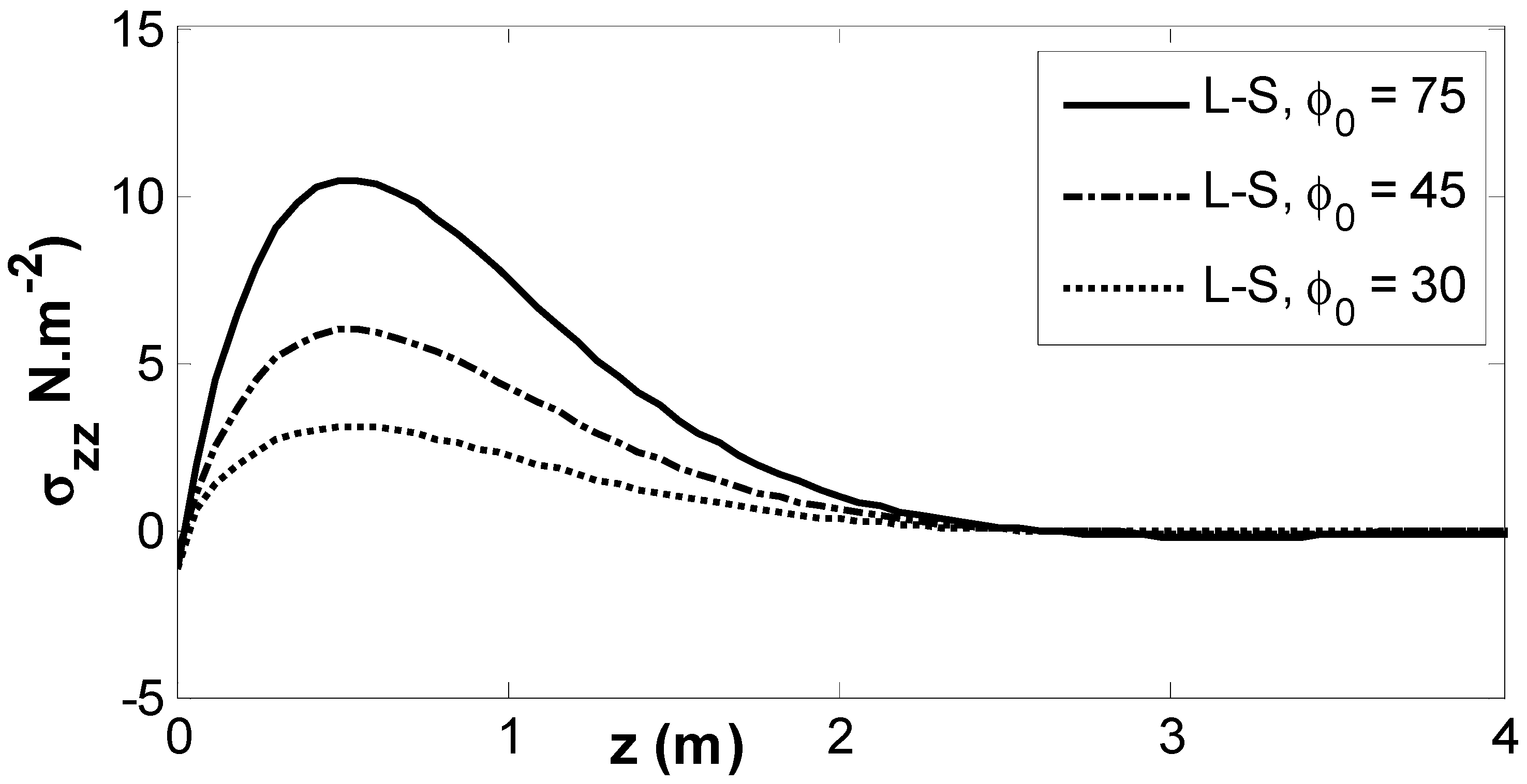
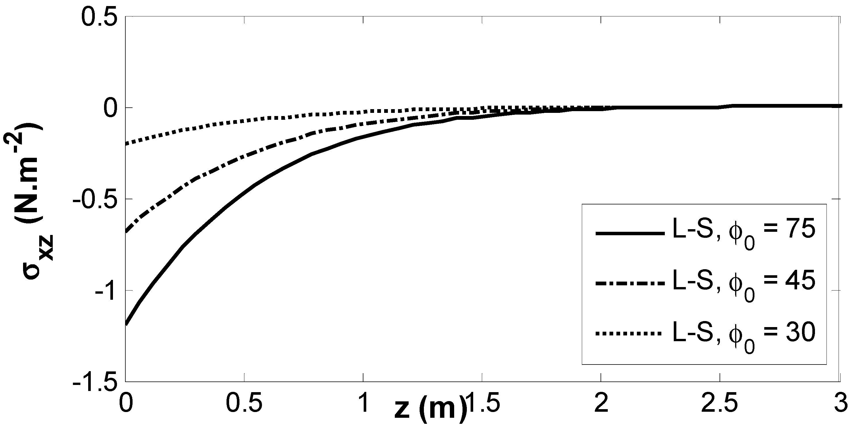
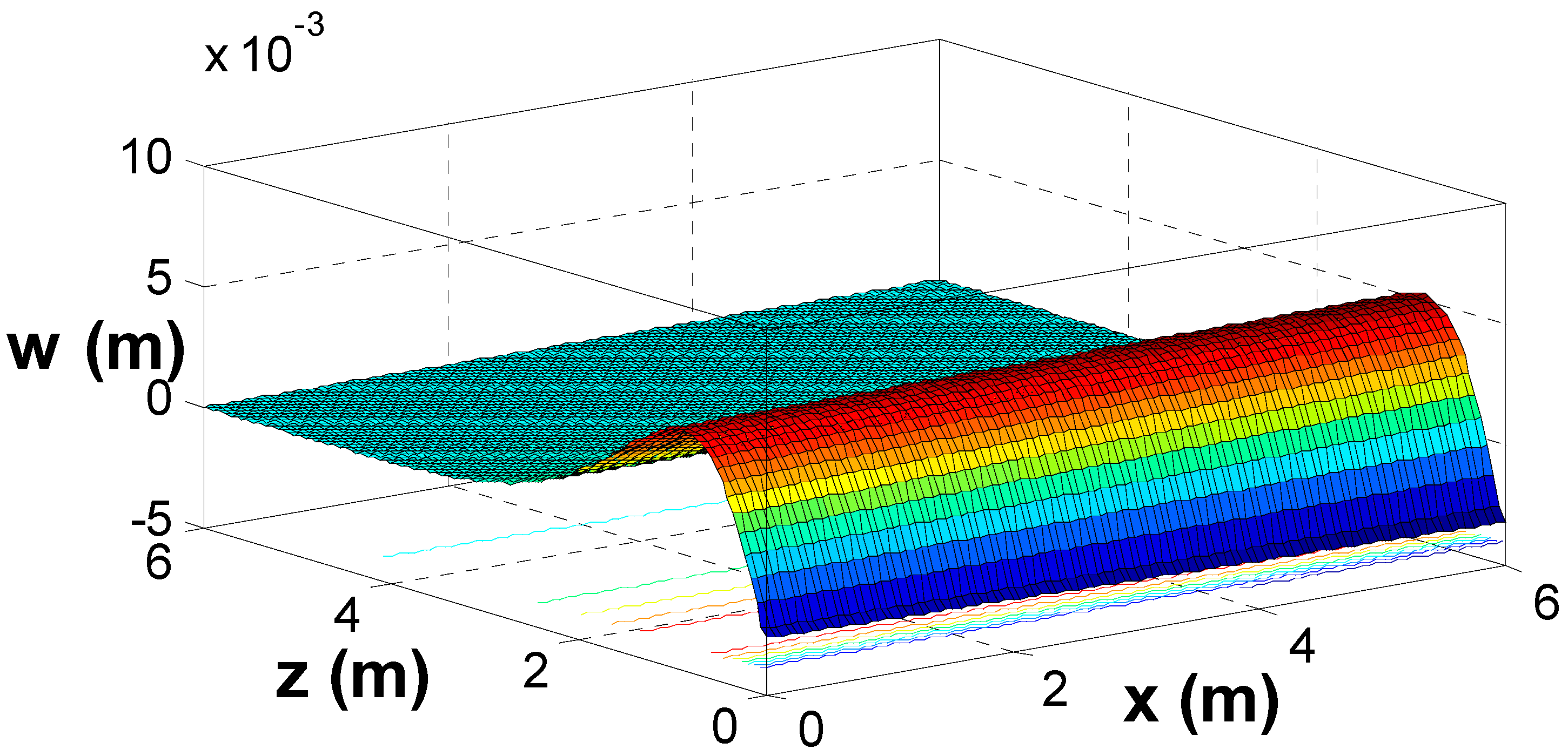
Figure 10, Figure 11, Figure 12 and Figure 13 display an examination according to the L-S model, showing the behavior of different factors under various magnitudes of the inclined load. Figure 10 depicts the fluctuation of u as a function of z . For various magnitudes of the inclined load, u decreases over the specific range of 0 x 2.5 and finally approaches zero. The increase in the inclined load causes the growth in u .  Figure 11 illustrates the dispersion of temperature θ with various values of the inclined load. It is noticed that θ starts by decreasing, then increases, and after that converges to zero. The modification of the inclined load causes the decrease in θ .  Figure 12 displays the fluctuation of σ z z for various magnitudes of the inclined load. σ z z fits to the boundary conditions, opens with a negative magnitude, rises to reach a maximum magnitude, then diminishes, and finally comes to zero as x increases. The increase in the inclined load causes the increase in σ z z .  Figure 13 shows the values of σ x z for different values of the inclined load. σ x z fits to the boundary conditions, opens with a negative value, and rises in the range of 0 x 3 . The increase in the inclined load causes the decrease in σ x z .  Figure 14, Figure 15 and Figure 16 entertain 3D surface curves for θ ,   w ,   σ x z via the L-S model. The results of the of the gravity field, Hall parameter, empirical solid constant, and inclined load on wave propagation in a thermoelastic fiber-reinforced medium have been explained. These figures are useful for addressing the dependence of these physical variables on the vertical distance.

7. Conclusions

The theoretical and numerical results show that several factors significantly impact all the physical fields taken into consideration. The results of the work mentioned in the preceding sections are the following conclusions.
  • The gravity field significantly impacts the magnitudes of the physical fields.
  • It is clear from Figure 4, Figure 5 and Figure 6 that the Hall current has an appreciable effect on the magnitude of physical fields.
  • The inclined load has a considerable effect on the magnitudes of physical fields.
  • All physical fields are subject to alteration, and are significantly impacted by the empirical solid constant.
  • All physical field variations approach a zero value with growing distance of z , and all physical fields are continuous.
The results of our study are a significant development for various innovative engineering applications. For example, in aerospace engineering, where materials are vulnerable to high magnetic fields and variable temperatures, our framework can modify the design of composite materials to guarantee greater reliability and efficiency. A comparison is made with the previous results obtained, which indicated the strong impact of the external parameters on the behaviors of mechanical load on the fiber-reinforced thermoelastic medium.

Author Contributions

Methodology, S.M.S., H.S.G. and S.M.A.-D.; Software, S.M.S.; Formal analysis, E.K.J. and S.M.A.-D.; Investigation, S.M.A.-D.; Data curation, S.M.S.; Writing – original draft, E.K.J.; Project administration, H.S.G.; Funding acquisition, E.K.J. All authors have read and agreed to the published version of the manuscript.

Funding

This work was supported and funded by the Deanship of Scientific Research at Imam Mohammad Ibn Saud Islamic University (IMSIU) (grant number IMSIU-DDRSP2502).

Data Availability Statement

The original contributions presented in this study are included in the article. Further inquiries can be directed to the corresponding author.

Conflicts of Interest

The authors declare no conflicts of interest.

Abbreviations

σ i j stress tensor H ¯ = (   0 ,     H 0 ,   0 ) magnetic field with constant intensity
e k k dilation τ 0 thermal relaxation time
e i j strain tensor a ( 1 ,   0 ,     0 ) fiber-direction as a ( a 1 ,   a 2 ,     a 3 ) , a 1 2 + a 2 2 + a 3 2 = 1 .
δ i j Kronecker delta T thermal temperature
ρ mass density T 0 reference temperature, T T 0 / T 1 , θ = T T 0
C E specific heat at constant strain α t linear thermal expansion coefficient, γ = (   3 λ + 2 μ   ) α t ,    
λ , μ elastic constants μ 1 , λ 1 , α 1 , β 1 , μ T 1 , μ L 1 constants of material
t time α * an empirical material constant
u ¯   = ( u , 0 , w ) the displacement vector u * ( z ) the function amplitude u ( x , z , t )
K thermal conductivity s complex constant
b a wave number in x -direction μ 0 permeability of magnetic field
( μ L μ T ) , α , β parameters of reinforcement ε 0 permeability of electric field
J ¯ vector of current density u ˙ ¯ velocity of the medium
m = Ω e τ e Hall parameter τ e electron relaxation time
Ω e = e B 0 m e cyclotron frequency B 0 induction of magnetic field
e charge of electron m e mass of electron
n e density of electron number i - 1
σ 0 = e 2 n e τ e m e the electrical conductivity

References

  1. Duhamel, J. Some memoire sur les phenomenes thermo-mechanique. J. l’École Polytech. 1837, 15, 1–31. [Google Scholar]
  2. Neumann, F. Vorlesungen über die Theorie der Elasticität; BG Teubner: Leipzig, Germany, 1885. [Google Scholar]
  3. Biot, M.A. Mechanics of Incremental Deformation; Wiley: New York, NY, USA, 1965. [Google Scholar]
  4. Lord, H.; Shulman, Y. A generalized dynamical theory of thermoelasticity. J. Mech. Phys. Solid 1967, 15, 299–309. [Google Scholar] [CrossRef]
  5. Ignaczak, J.; Bialy, J. Domain of influence in thermoelasticity with one relaxation time. J. Therm. Stress. 1980, 3, 391–399. [Google Scholar] [CrossRef]
  6. Sherief, H. State space formulation for generalized thermoelasticity with one relaxation time including heat sources. J. Therm. Stress. 1993, 16, 163–176. [Google Scholar] [CrossRef]
  7. He, T.; Cao, L. A problem of generalized magneto-thermoelastic thin slim strip subjected to a moving heat source. Math. Comp. Model. 2009, 49, 1710–1720. [Google Scholar] [CrossRef]
  8. Abo-Dahab, S.M.; Abbas, I.A. LS model on thermal shock problem of generalized magneto-thermoelasticity for an infinitely long annular cylinder with variable thermal conductivity. Appl. Math. Model. 2011, 35, 3759–3768. [Google Scholar] [CrossRef]
  9. Heydarpour, Y.; Malekzadeh, P.; Gholipour, F. Thermoelastic analysis of FG-GPLRC spherical shells under thermo-mechanical loadings based on Lord-Shulman theory. Compos. B Eng. 2019, 164, 400–424. [Google Scholar] [CrossRef]
  10. Sobhy, M.; Zenkour, A.M. Refined Lord-Shulman theory for 1D response of skin tissue under Ramp-type heat. Materials 2022, 15, 6292. [Google Scholar] [CrossRef]
  11. Abouelregal, A.E.; Askar, S.S.; Marin, M.; Mohamed, B. The theory of thermoelasticity with a memory-dependent dynamic response for a thermo-piezoelectric functionally graded rotating rod. Sci. Rep. 2023, 13, 9052. [Google Scholar] [CrossRef] [PubMed]
  12. Zenkour, A.M.; El-Shahrany, H.D.; El-Mekawy, H.F. Magneto-photo-thermoelastic influences on a semiconductor hollow cylinder via a series-one-relaxation model. Commun. Nonliner Sci. Numer. Simul. 2024, 139, 108295. [Google Scholar] [CrossRef]
  13. Said, S.M. Influence of gravitational on a rotating nonlocal thermoelastic medium with thermal variable conductivity. J. Comput. Appl. Math. 2025, 454, 116180. [Google Scholar] [CrossRef]
  14. Hall, E.H. On a new action of the magnet on electric currents. Am. J. Math. 1879, 2, 287–292. [Google Scholar] [CrossRef]
  15. Cowling, T.G. Magneto Hydrodynamics; Wiley Inter Science: New York, NY, USA, 1957. [Google Scholar]
  16. Salem, A.M. Hall-current effects on MHD flow of a power-law fluid over a rotating disk. J. Korean Phys. Soc. 2007, 50, 28–33. [Google Scholar] [CrossRef]
  17. Reddy, P.B.; Rao, A.J. Radiation and thermal diffusion effects on an unsteady MHD free convection mass transfer flow past an infinite vertical porous plate with Hall current and heat source. J. Eng. Phys. Thermophys. 2011, 84, 1369–1378. [Google Scholar] [CrossRef]
  18. Zakaria, M. Effects of Hall current and rotation on magneto micropolar generalized thermoelasticity due to ramp-type heating. Int. J. Electr. Appl. 2012, 2, 24–32. [Google Scholar] [CrossRef]
  19. Kumar, R.; Vohra, R. Effect of Hall current in thermoelastic materials with double porosity structure. Int. J. Appl. Mech. Eng. 2017, 22, 303–319. [Google Scholar] [CrossRef]
  20. Bhatti, M.M.; Ellahi, R.; Zeeshan, A.; Marin, M.; Ijaz, N. Numerical study of heat transfer and Hall current impact on peristaltic propulsion of particle-fluid suspension with compliant wall properties. Mod. Phys. Lett. B 2019, 33, 1950439. [Google Scholar] [CrossRef]
  21. Kaur, I.; Singh, K. Plane wave in non-local semiconducting rotating media with Hall effect and three-phase lag fractional order heat transfer. Int. J. Mech. Mater. Eng. 2021, 16, 14. [Google Scholar] [CrossRef]
  22. Deswal, S.; Sheokand, P.; Punia, B.S. Interactions due to Hall current and photothermal effect in a magneto-thermoelastic medium with diffusion and gravity. Acta Mech. 2024, 235, 235–254. [Google Scholar] [CrossRef]
  23. Noda, N. Thermal stresses in materials with temperature-dependent properties. In Thermal Stresses I; Hetnarski, R.B., Ed.; North-Holland: Amsterdam, The Netherlands, 1986. [Google Scholar]
  24. Roy Choudhuri, S.K.; Chatterjee Roy, G. Temperature-rate dependent magnetothermoelastic waves in a finitely conducting elastic half-space. Comput. Math. Appl. 1990, 19, 85–93. [Google Scholar] [CrossRef]
  25. Szuecs, F.; Werner, M.; Sussmann, R.S.; Pickles, C.S.J.; Fecht, H.J. Temperature dependence of Young’s modulus and degradation of chemical vapor deposited diamond. J. Appl. Phys. 1999, 86, 6010–6017. [Google Scholar] [CrossRef]
  26. Aouadi, M. Generalized thermo-piezoelectric problems with temperature-dependent properties. Int. J. Solids Struct. 2006, 43, 6347–6358. [Google Scholar] [CrossRef]
  27. Othman, M.I.A.; Kumar, R. Reflection of magneto-thermoelasticity waves with temperature dependent properties in generalized thermoelasticity. Int. Commun. Heat Mass Transf. 2009, 36, 513–520. [Google Scholar] [CrossRef]
  28. Abbas, I.A. Eigenvalue approach in a three-dimensional generalized thermoelastic interactions with temperature-dependent material properties. Comp. Math. Appl. 2014, 68, 2036–2056. [Google Scholar] [CrossRef]
  29. Li, X.; Li, C.; Xue, Z.; Tian, X. Investigation of transient thermo-mechanical responses on the triple-layered skin tissue with temperature dependent blood perfusion rate. Int. J. Therm. Sci. 2019, 139, 339–349. [Google Scholar] [CrossRef]
  30. Said, S.M. Effects of phase-lags, rotation, and temperature-dependent properties on plane waves in a magneto-microstretch thermoelastic medium. Mech. Basic Des. Struct. Mach. 2021, 49, 534–552. [Google Scholar] [CrossRef]
  31. Das, N.; De, S.; Sarkar, N. Reflection of temperature rate-dependent coupled thermoelastic waves on a non-local elastic half-space. Math. Mech. Solids 2023, 28, 1232–1254. [Google Scholar] [CrossRef]
  32. Deswal, S.; Kalkal, K.K.; Dhankhar, P.; Poonia, R. Reflection of plane waves in a nonlocal transversely isotropic micropolar thermoelastic medium with temperature-dependent properties. J. Vib. Eng. Technol. 2024, 12, 8595–8612. [Google Scholar] [CrossRef]
  33. Said, S.M.; Othman, M.I.A.; Eldemerdash, M.G. Effect of temperature-dependent properties and gravity on a nonlocal poro-thermoelastic medium with MDD via G-L model. J. Vib. Eng. Technol. 2025, 13, 116. [Google Scholar] [CrossRef]
  34. Belfield, A.J.; Rogers, T.G.; Spencer, A.J.M. Stress in elastic plates reinforced by fiber lying in concentric circles. J. Mech. Phys. Solid 1983, 31, 25–54. [Google Scholar] [CrossRef]
  35. Said, S.M. Eigenvalue approach on a problem of magneto-thermoelastic rotating medium with variable thermal conductivity: Comparisons of three theories. Waves Random Complex Media 2021, 31, 1322–1339. [Google Scholar] [CrossRef]
  36. Othman, M.I.A.; Said, S.M.; Marin, M. A novel model of plane waves of two-temperature fiber-reinforced thermoelastic medium under the effect of gravity with three-phase lag model. Int. J. Numer. Methods Heat Fluid Flow 2019, 29, 4788–4806. [Google Scholar] [CrossRef]
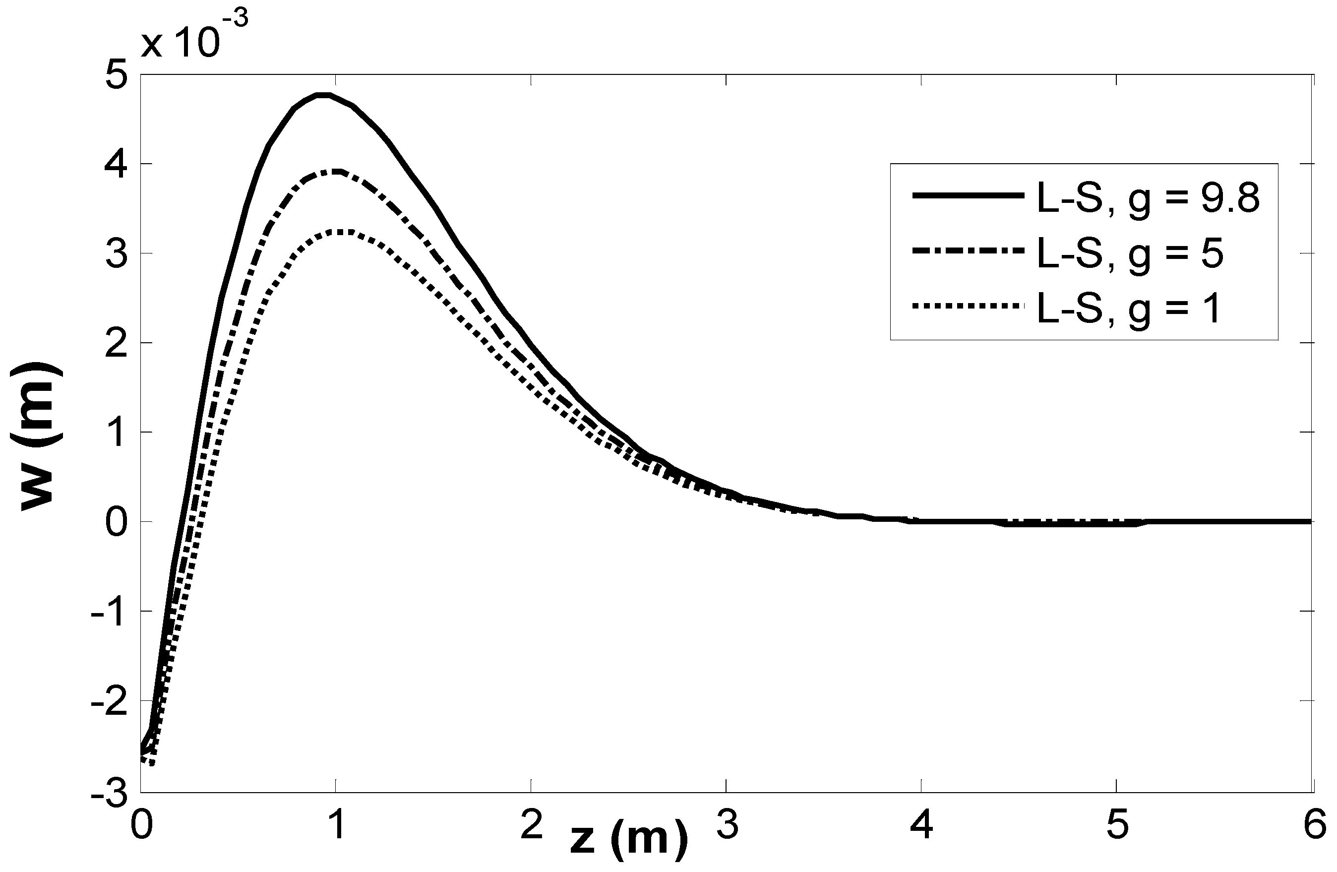
Figure 1. Vertical displacement dispersion w for various magnitudes of the gravitational force.
Crystals 15 00924 g001
Figure 2. Thermal temperature dispersion θ for various magnitudes of the gravitational force.
Crystals 15 00924 g002
Figure 3. Dispersion of stress component σ z z . for various magnitudes of the gravitational force.
Crystals 15 00924 g003
Figure 4. Vertical displacement dispersion w for various magnitudes of the Hall parameter.
Crystals 15 00924 g004
Figure 5. Thermal temperature dispersion θ for various magnitudes of the Hall parameter.
Crystals 15 00924 g005
Figure 6. Dispersion of stress component σ z z . for various magnitudes of the Hall parameter.
Crystals 15 00924 g006
Figure 7. Vertical displacement dispersion w for various magnitudes of the empirical solid constant.
Crystals 15 00924 g007
Figure 8. Thermal temperature dispersion θ for various magnitudes of the empirical solid constant.
Crystals 15 00924 g008
Figure 9. Dispersion of stress component σ z z . for various magnitudes of the empirical solid constant.
Crystals 15 00924 g009
Figure 10. Horizontal displacement dispersion u for various magnitudes of the inclined load.
Crystals 15 00924 g010
Figure 11. Thermal temperature dispersion θ for various magnitudes of the inclined load.
Crystals 15 00924 g011
Figure 12. Dispersion of stress component σ z z . for various magnitudes of the inclined load.
Crystals 15 00924 g012
Figure 13. Dispersion of stress component σ x z . for various magnitudes of the inclined load.
Crystals 15 00924 g013
Figure 14. Thermal temperature dispersion θ in 3D via the L-S hypothesis.
Crystals 15 00924 g014
Figure 15. Vertical displacement dispersion w in 3D via the L-S hypothesis.
Crystals 15 00924 g015
Figure 16. Dispersion of stress component σ x z . in 3D via the L-S hypothesis.
Crystals 15 00924 g016
Disclaimer/Publisher’s Note: The statements, opinions and data contained in all publications are solely those of the individual author(s) and contributor(s) and not of MDPI and/or the editor(s). MDPI and/or the editor(s) disclaim responsibility for any injury to people or property resulting from any ideas, methods, instructions or products referred to in the content.