Article

Wide Temperature Stability of BaTiO3-NaNbO3-Gd2O3 Dielectric Ceramics with Grain Core–Shell Structure

School of Materials Science and Engineering, Key Laboratory of Advanced Ceramics and Machining Technology of Ministry of Education, Tianjin University, Tianjin 300072, China
*
Author to whom correspondence should be addressed.
Crystals 2024, 14(6), 488; https://doi.org/10.3390/cryst14060488
Submission received: 28 April 2024 / Revised: 16 May 2024 / Accepted: 18 May 2024 / Published: 23 May 2024
(This article belongs to the Special Issue Advanced Ferroelectric, Piezoelectric and Dielectric Ceramics)

Abstract

:
As consumer electronics and industrial control systems continue to evolve, the operating temperature range of capacitors is gradually increasing. Barium titanate-based ceramic capacitors are widely used in the field of high dielectrics, so temperature-stable barium titanate-based dielectric materials have been a hot research topic in the field of dielectric ceramics. The construction of a core–shell structure by unequal doping is an effective way to obtain temperature-stable dielectric materials. At the same time, this structure retains part of the highly dielectric tetragonal phase, and materials with overall high dielectric constants can be obtained. In this work, we prepared BaTiO3-xNaNbO3-0.002Gd2O3 (x = 1.0–6.0 mol%) as well as BaTiO3-0.05NaNbO3-yGd2O3 (y = 0–0.30 mol%) dielectric ceramics. On the basis of high-electronic-bandgap NaNbO3-modified BaTiO3 dielectric ceramics, a core–shell structure with a larger proportion of core phase was obtained by further doping the amphiphilic rare-earth oxide Gd2O3. By designing this core–shell structure, the temperature stability range of capacitors can be expanded. At a doping level of 5.0 mol% NaNbO3 and 0.20 mol% Gd2O3, the room temperature dielectric constant εr = 4266 and dielectric loss tan δ = 0.95% conforms to the X8R standard (from −55 °C to 150 °C, TCC < ±15%); volume resistivity ρv = 10,200 GΩ·cm and breakdown strength Eb = 13.5 kV/mm is attained in BaTiO3-based ceramics. The system has excellent dielectric and insulating properties; it provides a new solution for temperature-stable dielectric ceramics.

1. Introduction

Ceramic capacitors are indispensable components in communications, pulse devices and consumer electronics due to their high dielectric constant, low dielectric loss and wide operating temperature range [1,2,3]. The integration and miniaturization of electronic components leads to higher operating temperature ranges and higher operating field strengths, which makes the capacitance–temperature stability and insulation properties of ceramics increasingly important [4]. BaTiO3 (BT) is one of the most widely used lead-free high-dielectric materials [5,6]. The microstructure of BT-based ceramics can be modulated by means of doping modification, adjusting the powder preparation process and sintering process, which gives them different dielectric properties [4,7,8,9,10].
Although pure barium titanate has a high dielectric constant and a suitable Curie temperature, its temperature stability is poor and it needs to be doped and modified to improve its temperature stability. Constructing a core–shell structure is an effective means of increasing the temperature stability of BT while maintaining a high dielectric level, which can be achieved by doping the A or B sites with ions of lower solid solubility [11,12]. The enriched and rare regions of dopant ions are the shell phase and core phase, respectively, which form a double dielectric peak. The inhomogeneity of elemental distribution leads to the disruption of long-range ordering, generating polar nanoregions (PNRs) with different phase transition temperatures, which in turn leads to phase transition relaxation that enhances the capacitance–temperature stability of BT-based ceramic capacitors [13,14]. At the same time, the doping of low-solid-solubility ions leads to an increase in lattice strain energy and a decrease in the rate of grain boundary movement, which easily obtains a fine grain structure with a high degree of densification. Fine grain structures designed through grain engineering provide better insulation due to larger grain boundary ratios [10]. The NaNbO3-modified BaTiO3 system (BT-NN) is a core–shell structure with potential applications. It has been reported that NN with a high electronic band gap (3.58 eV) can increased interatomic bonding linked to the BO6 octahedron and lattice network, which has the effect of improving insulating properties [15,16,17]. Moreover, the internal stresses induced by the inhomogeneous solid solution of NN in the BT lattice can significantly reduce the Curie temperature of the shell phase, which leads to a broadening of the temperature range over which the dielectric constant is stabilized [18]. For the BT-NN system, the large radius Nb5+ (0.072 nm) replaces Ti4+ (0.061 nm) at the B-site and the small radius Na+ (0.102 nm) replaces Ba2+ (0.161 nm) at the A-site [16]. Due to the mismatch of the charge and ionic radius, Na+ has difficulty forming the 12-coordination of the standard perovskite A-site ion. Oxygen octahedra are deflected to reduce repulsion between oxygen ions to optimize the coordination environment of the A-site ion [19]. It also reduces the displacement space of the B-site ions and suppresses ion displacement polarization, leading to a sudden drop in the Curie temperature and a decrease in the dielectric constant at high temperatures, reducing its temperature stability range [18]. Numerous studies have reported the improvement of the high-temperature performance of BT-NN by introducing high Curie temperature components to form a ternary system. These methods widen the operating temperature range of BT-based capacitors, but greatly suppress their dielectric constant, limiting the application of the materials [20,21,22]. To obtain BT-NN ceramics with good capacitance–temperature stability and a high dielectric constant, increasing the content of the core phase (ferroelectric phase) in the core–shell structure is necessary. Co-doping is a method to optimize the core–shell structure by doping with multiple or amphoteric elements to suppress the diffusion of shell elements. This method designs a thinner shell layer and retains more of the high dielectric constant phase, resulting in optimized capacitance–temperature stability [23,24].
Based on the above background, this study aims to prepare BT-based dielectric materials with a high temperature stability and high dielectric constant by designing core–shell structures. The research objective of this work is to prepare dielectric materials that comply with the EIA X8R standard (from −55 °C to 150 °C, TCC < ±15%) and have a dielectric constant above 4000. In this context the material has stable insulating properties. In this work, BaTiO3-xNaNbO3-0.002Gd2O3 (x = 1.0–6.0 mol%) and BaTiO3-0.05 NaNbO3-yGd2O3 (y = 0.00–0.30 mol%) ceramic samples were prepared by using pre-synthesized NN and amphoteric rare-earth oxide Gd2O3-modified BT. Compared with the synthesis methods of powders from oxides as well and carbonates, the pre-synthesis method has a lower sintering temperature and an easier way to build core–shell structures. The amphiphilic rare earth element Gd can enter the A-site and B-site at the same time as the donor and acceptor, respectively, due to its small ionic radius. This self-compensating mechanism can also promote the formation of core–shell structures. As a result, the prepared ceramics exhibit a well-defined core–shell structure and a fine crystal structure, which optimize the dielectric-temperature stability as well as the breakdown strength of the samples, respectively. Samples formulated with BaTiO3-0.05NaNbO3-0.002Gd2O3 achieved the X8R standard with εr = 4266 and tan δ = 0.95%; meanwhile, excellent insulation properties were obtained with ρv = 10,200 GΩ·cm and Eb = 13.5 kV/mm.

2. Experiments

2.1. Sample Preparation

BT-based ceramic capacitor samples with different NN and Gd2O3 contents were synthesized using the conventional solid-phase method. The samples were named BaTiO3-xNaNbO3-0.002Gd2O3 (simplified as BT-xNN-0.002Gd, x = 1.0–6.0 mol%) and BaTiO3-0.05NaNbO3-yGd2O3 (simplified as BT-0.05NN-yGd, y = 0–0.30 mol%) depending on the composition. The ceramic samples were prepared from barium titanate (Shandong Guocera Materials, prepared by hydrothermal method) as the main ingredient; NN (pre-synthesized from Na2CO3 (98.0%, Hynes & Co., Tianjin, China) and Nb2O5 (99.0%, Hynes & Co., Tianjin, China) at 800 °C/240 min) based on 1.0–6.0 mol% of the main ingredient; Gd2O3 (99.99%, Hynes & Co., Tianjin, China) based on 0–0.30 mol% of the main ingredient; ZnO (97.0%, Hynes & Co., Tianjin, China) based on 1.2 wt.% of the main ingredient; and CaZrO3 (pre-synthesized from CaCO3 (99.0%, Hynes & Co., Tianjin, China) and ZrO2 (99.99%, Hynes & Co., Tianjin, China) at 1000 °C/120 min) based on 0.5 wt.% of the main ingredient.
All samples were ball milled using agate grinding balls with anhydrous ethanol as the grinding medium for 240 min at a motor speed of n = 400 r/min. The mixed slurry was dried and then granulated by adding 7 wt.% PVA through 30 mesh sieve. The granulated powder was pressed into a circular flat plate with a diameter of 13 mm and a thickness of 1.1 mm. The raw ceramic blanks were discharged from the binder at 600 °C and sintered at 1160 °C/120 min to obtain ceramic samples. After cooling in the furnace, the thickness of the sample is about 1.0 mm and the diameter is about 11.16–11.20 mm. Conductive silver paste was printed on both sides of the sample and fired at 750 °C.

2.2. Sample Characterization and Testing

X-ray diffractometer (XRD, D8 Advanced, Brooklyn, Germany) was used for the physical characterization, which was performed by Cu Kα radiation with a scanning range of 10°–90° and a scanning rate of 0.1°/s with a step size of 0.02°. Cold field emission scanning electron microscope (SEM, S-4800, Hitachi, Tokyo, Japan) was used for micro-morphological analysis of the samples. Transmission electron microscopy (TEM, JEM-F200, Hitachi, Tokyo, Japan) and accompanying EDS equipment were used for grain structure analysis of the samples. LCR meter (TH2827C, Tonghui, Changzhou, China) was used to measure the capacitance and dielectric loss of the samples. High insulation resistance measuring instrument (ZC-90, Taio Company, Changzhou, China) was used to measure the resistance of the samples. Voltage withstand tester (LK2674A, Languang, China, Tianjin, China) was used to measure the room temperature breakdown field strength of the samples.

2.3. Research Methods

The samples were fixed on a fixture and connected to an LCR meter, and the capacitance C and dielectric loss tan δ of the samples were read at 1 kHz over a temperature range of −55 °C to 150 °C. The dielectric constant of the circular flat capacitor is calculated from Equation (1).
ε r = 14.4 C · d D 2
where εr is relative dielectric constant of the sample, C is capacitance of the sample (nF), d is thickness of the sample (mm) and D is diameter of the sample (mm). The dielectric constant and dielectric loss from −55 °C to 150 °C were plotted as dielectric constant/dielectric loss temperature curves. Temperature coefficient of capacitor (TCC) curves were plotted according to Equation (2) using 25 °C as a reference.
T C C = ε ε 25 ε 25
where εr is dielectric constant of the sample at a certain temperature and ε25°C is dielectric constant of the sample at 25 °C. The volume resistivity was tested at a voltage of 500 V. The volume resistivity ρv of the sample was calculated according to Equation (3).
ρ v = R π D 2 4 d
In the breakdown field strength test, in order to prevent the high-voltage arc from breaking through the air, the sample should be encapsulated with epoxy resin in advance, and the test should be carried out after it has been left to cure completely. The breakdown field strength is determined according to Equation (4).
E b = E d
where Eb is breakdown field strength of the sample (kV/mm), E is voltage at breakdown (kV) and d is thickness of the sample (mm).

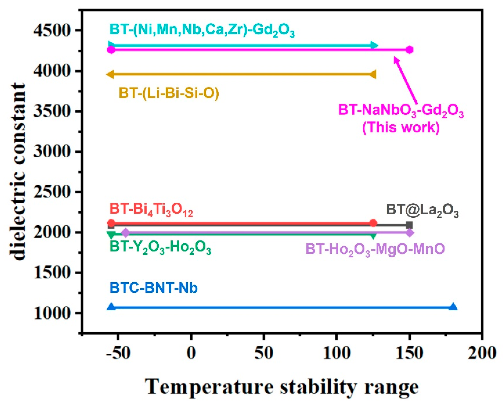
3. Results and Discussion
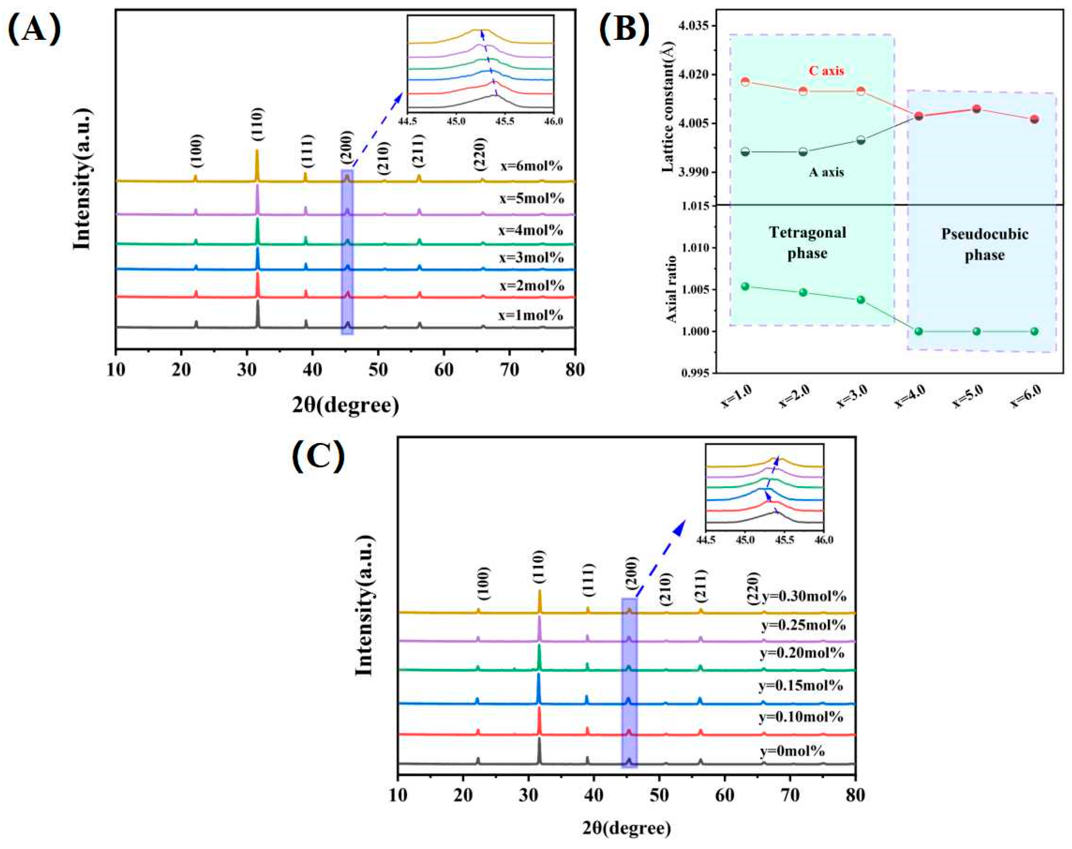
3.1. Phase Analysis

The XRD diffraction patterns and cell parameters of the BT-xNN-0.002Gd samples are shown in Figure 1A,B. Table 1 lists the ionic radii of various in situ and substituted ions. All samples in the formulation composition range show a single perovskite phase and present the (200) peak of the pseudocubic phase. As the NN content rises, Nb5+ (0.072 nm) enters the lattice replacing Ti4+ (0.061 nm), resulting in a decrease in the space for B-site ions to be displaced in the [B-O] octahedron; Na+ (0.102 nm) replaces Ba2+ (0.161 nm), leading to a decrease in the volume of the oxygen octahedron. The positive and negative charge centers tend to coincide, tetragonality decreases and cubicity increases. The crystal structure of the material gradually transforms to the pseudocubic phase and the reaction occurs as follows:
N a N b O 3 + B a T i O 3 N a B a + N b T i · + 6 O O
It is relatively difficult for Na+ to form 12-coordination due to its smaller radius and charge mismatch. Therefore, the solid solubility of Na+ in the BT lattice is lower than that of Nb5+ and the main reason for the change in lattice spacing is the solid solubility of Nb5+. This phenomenon is reflected in the XRD pattern as a gradual shift of the diffraction peaks to lower angles. Meanwhile, the core–shell structure is elementally gradient distributed and the diffraction peaks are diffuse single peaks.
When x exceeds 4.0 mol%, we can observe the (200) peak of the pseudocubic phase and another split peak at 45–46°, which is caused by a large enrichment of NN in the BT shell layer. The above results indicate that there is a clear boundary between the core–shell structure.
As shown in Figure 1B, when x = 1.0 mol%, the axial ratio c/a = 1.0051, which is decreased compared with the ideal tetragonal barium titanate axial ratio c/a 1.010 [25]. As the NN content increases, the axial rate c/a decreases gradually. When x is more than 4.0 mol%, the axial rate c/a = 1, which indicates that the sample has completely changed to the pseudocubic phase.
Table 1. Ionic radii of various in situ and substituted ions [23,26].
IonsCoordination Number (CN)Ionic Radius (nm)
Ba2+120.1610
Na+120.1020
Gd3+120.1253
Gd3+60.0938
Nb5+60.0720
Ti4+60.0610
O2-60.1400
The XRD diffraction pattern of the BT-0.05NN-yGd sample is shown in Figure 1C. The (200) peak of the BT-0.05NN sample (y = 0) does not split, which indicates that there is still no clear boundary between the core phase and the shell phase. With the co-doping of Gd and NN, the diffusion rate of NN and Gd in the lattice is reduced and tends to form a well-defined core–shell structure. As a result, a splitting peak appears at 45–46°. As a rare earth ion with a small radius, Gd3+ can enter the A-site and B-site in the BT lattice simultaneously, and the reaction occurred as follows:
G d 2 O 3 + B a T i O 3 G d B a · + G d T i + 6 O O
The lattice spacing becomes smaller when Gd3+ (0.1253 nm) enters the A-site in place of Ba2+ (0.1610 nm). In addition, the lattice spacing becomes larger when Gd3+ (0.0938 nm) enters the B-site in place of Ti4+ (0.061 nm). As the enlarged figure in Figure 1C shows, the position of the diffraction peak is shifted to a lower angle in BT-0.05NN-yGd samples (y < 0.15 mol%), which indicates that Gd3+ mainly enters the B-site. In addition, the diffraction peak starts to shift to a large angle in BT-0.05NN-yGd samples (y > 0.20 mol%), which shows that Gd3+ replaces more A-sites.

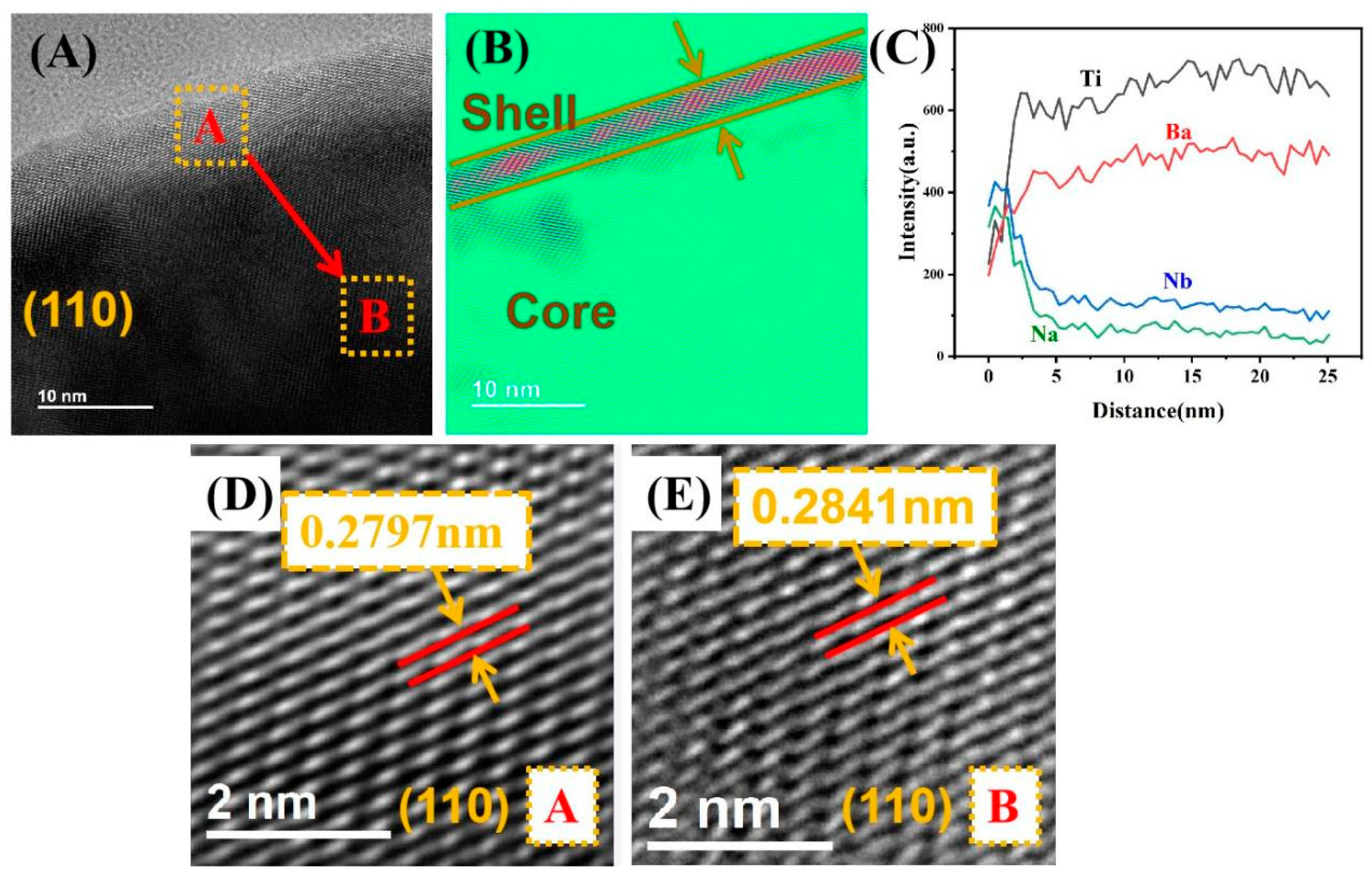
3.2. Morphological Analysis

Figure 2A,B shows the TEM bright-field and Fourier transform images of the grain in the BT-0.05NN-0.002Gd sample, respectively. It is clear from the image lining that a well-defined core–shell structure is formed in this region. Figure 2C illustrates the EDS pattern between region A to region B, where an inhomogeneous distribution of dopant elements can be observed. The shell phase has significant Nb and Na enrichment, while the core phase has low Nb and Na content. Figure 2D,E shows the enlarged images of the A region (shell) as well as the B region (core) of the grain in the BT-0.05NN-0.002Gd sample after the clarity treatment, respectively. Due to the large solid solution of Gd and NN in the shell layer, the lattice spacing becomes smaller. As shown in Figure 2D,E, the lattice spacing of the grain (110) shell layer (region A, 0.2797 nm) is smaller than that of the core layer (region B, 0.2841 nm) of the grain, which corresponds to the splitting peaks in the XRD patterns. The shrinkage of the lattice spacing in the outer layers of the grains leads to internal stresses within the grains, which transform into a pseudocubic phase at room temperature.
The typical microscopic morphology images of (BT-xNN-0.002Gd (x = 1.0 mol%, 3.0 mol%, 5.0 mol%, 6.0 mol%) are shown in Figure 3A–D and the insets demonstrate the corresponding grain size distribution. All samples show a relatively dense fine grain structure. With the increase in the NN content, the grain size of this system gradually decreases and the average grain size decreases from 0.59 μm at x = 1.0 mol% to 0.42 μm at x = 6.0 mol%. In addition, the distribution of the grain size also become more concentrated in the small size. This phenomenon can be explained by the substitution of several different valence ions, which increases the lattice strain energy and retards the grain boundary movement, resulting in a fine crystalline structure [27]. Typical SEM images of the BT-0.05NN-yGd samples (y = 0.00 mol%, 0.10 mol%, 0.20 mol%, 0.30 mol%) are shown in Figure 3E–H. The system already formed fine grains at y = 0 and the average grain size decreased from 0.48 μm at y = 0 mol% to 0.41 μm at y = 0.30 mol% with increasing Gd doping. The fine crystal structure is conducive to improving the capacitance–temperature stability and obtaining a smoother capacitance–temperature curve, as well as to improving the insulating properties of the ceramics [28].

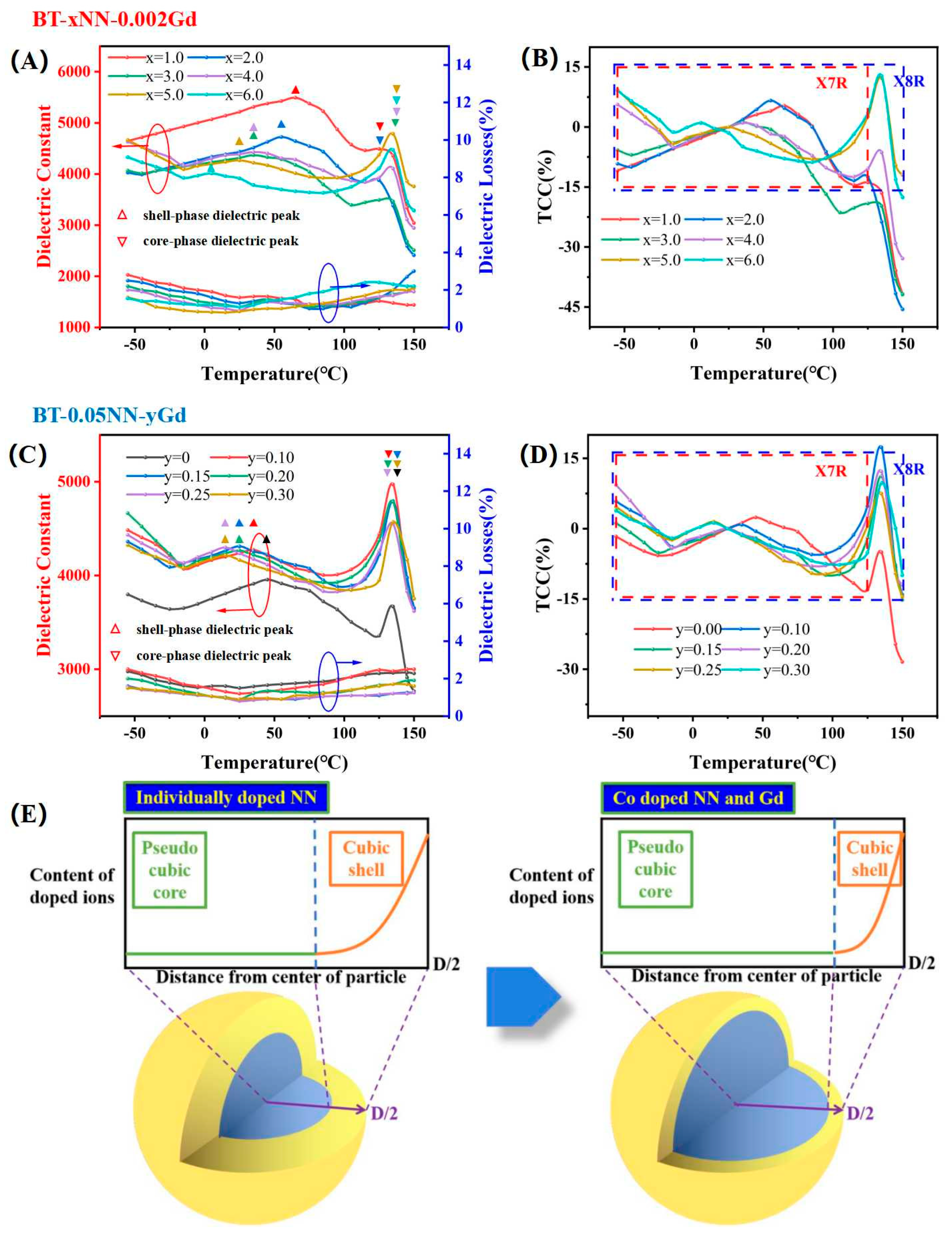
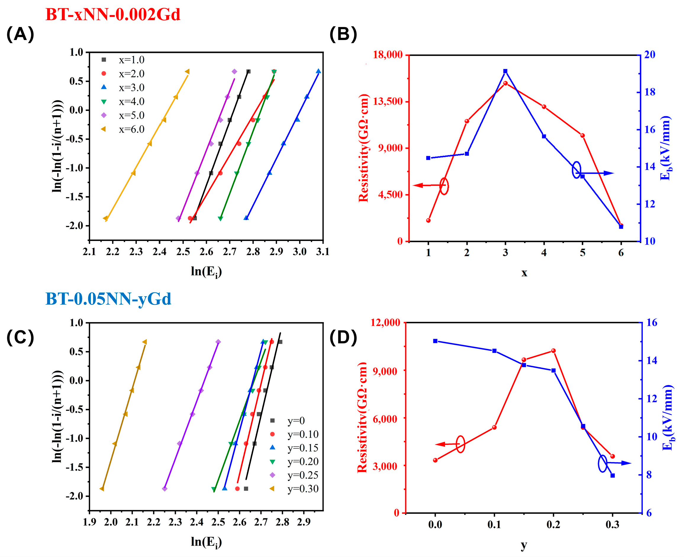
3.3. Dielectric and Insulation Properties

Figure 4A,B shows the temperature dependence of the dielectric constant and dielectric loss in BT-xNN-0.002Gd ceramics (x = 1.0–6.0 mol%). For the BT-xNN-0.002Gd ceramic system, the substitution of ions with different radii and the internal stresses of the core–shell structure inhibit the ion displacement polarization as the NN content increases, the Curie temperature is significantly shifted towards the low temperature range and the room temperature dielectric constant decreases from 5460 (x = 1.0 mol%) to 3950 (x = 6.0 mol%). This inhomogeneous distribution of dopant ions in the shell layer disrupts the long-range ordering of the ferroelectric arrangement, forming polar nanoregions (PNRs) with different phase-transitions, which improves the temperature-stability properties of the dielectric constant [29].
The core–shell structure is typically characterized by two dielectric peaks on the dielectric–temperature curve. One is the Curie peak of the shell phase in the low temperature range and the other is the dielectric peak of the core phase at the tetragonal–cubic phase transition temperature of barium titanate. These dielectric peaks are labeled in Figure 4A,C. In Figure 4A,B, the dielectric constant and dielectric peak of the high temperature range decrease with the increase in NN in BT-xNN-0.002Gd ceramics (x < 3.0 mol%). Due to the decrease in the Curie temperature, BT-xNN-0.002Gd ceramics (x = 1.0 mol%, 2.0 mol%) reach the standard of X7R. In the BT-xNN-0.002Gd ceramics (x > 4.0 mol%), the high-temperature dielectric peak of the dielectric curve is much sharper, which exhibits a typical stable dielectric temperature profile. The variation of the Curie temperatures of samples x = 1.0, 2.0 and 3.0 is due to the peak-shifting and peak-pressing effects of the NaNbO3-doped shell phases. However, the Curie temperatures for samples x = 4.0, 5.0 and 6.0 return to the high-temperature region (135 °C) due to the enrichment of NaNbO3 which leads to charge mismatching and the generation of defective dipoles in the BaTiO3 lattice. At high temperatures, B-site ion displacement is enhanced and the sample macroscopically shows a larger polarity and this spontaneous polarization in turn promotes the reorientation of the defective dipoles. Thus, the higher dielectric constants of samples x = 4.0, 5.0 and 6.0 at high temperatures are the result of the synergistic effect of ion displacement polarization and defect dipole polarization, leading to sharper dielectric peaks at this Curie temperature. The core–shell structure optimizes the dielectric constant-temperature stability in the high temperature range, which reaches the standard of X8R in the BT-xNN-0.002Gd ceramics (x = 5.0 mol%, 6.0 mol%).
Figure 4C,D shows the temperature dependence of the dielectric constant and dielectric loss in the BT−0.05NN−yGd system (y = 0.00−0.30 mol%). The dielectric constant of BT−0.05NN ceramics is lower in the high temperature range, which is caused by the thicker shell layer in the core–shell structure. In the BT−0.05NN−yGd ceramics (y > 0.10 mol%), the dielectric constants are enhanced in all temperature ranges, especially in the high temperature range, in which the dielectric constant shows a large recovery and a sharper Curie peak. The capacitance temperature characteristics of the BT-0.05NN-yGd ceramics are also optimized from X7R (y = 0) to X8R (y = 0.15−0.30 mol%). As mentioned above, Gd2O3 and NaNbO3 have the low solid solubility in the BT lattice. Moreover, co-doping will further reduce diffusion rates of dopant ions, as shown in Figure 4E, forming a core–shell structure with significant compositional differences and clear boundaries. As a result, a thinner shell layer is formed in the core–shell structure of the BT-0.05NN-yGd ceramics (y = 0.15−0.30 mol%), leading to a larger volume share of the nuclear phase at high Curie temperatures. Additionally, the sites of Gd substitution affect the dielectric properties of BT−0.05NN−yGd ceramics (y = 0.00–0.30 mol%). According to the XRD results, in the BT−0.05NN-yGd system (y < 0.15 mol%), the acceptor produces oxygen vacancies  G d T i / V O · ·  and lattice distortions, which introduce a defective dipole polarization mechanism in the shell layer, leading to an increase in permittivity at room temperature, whereas at high temperatures, the defective dipole undergoes orienting and the shell defective dipole polarization combined with ionic shift polarization in the nuclear layer further enhances permittivity at high temperatures. In the BT-0.05NN-yGd system (y > 0.15 mol%), Gd3+ starts to enter the A-site due to the small radius of the Gd3+ ions (0.1253 nm), thus suppressing the ionic displacement polarization, and the self-compensation mechanism in turn reduces the defect concentration, leading to a decrease in the dielectric constant.
Figure 5A,B shows the Weibull distribution of the BT-xNN-0.002Gd ceramics and the relationship between the x content and the resistivity/breakdown field strength. When the doping amount of NN is low, the high electronic bandgap NN enters into the BT lattice to form a high electronic bandgap microstructure. Starting from x = 0 (Eb = 14.4 kV/mm; ρv = 2.02 × 10³ GΩ·cm), the breakdown field strength and resistivity of the BT-xNN-0.002Gd ceramics increase continuously with the increasing doping amount of x and reach a peak (Eb = 19.13 kV/mm; ρv = 1.53 × 10⁴ GΩ·cm) at x = 3.0 mol%. When x > 4.0 mol%, a large number of heterovalent ions accumulate in the shell layer to generate more carriers, while some low-solubility sodium ions remain at the grain boundaries, which decreases the resistivity and insulating field strength in BT-xNN-0.002Gd ceramics.
Figure 5C,D shows the Weibull distribution of the BT-0.05NN-yGd ceramics and the relationship between the y content and the resistivity/breakdown field strength. The resistivity of the BT-0.05NN-yGd ceramics reaches the peak (ρv = 1.02 × 10⁴ GΩ·cm) at y = 0.20 mol%; however, the breakdown field strength of the BT-0.05NN-yGd ceramics decreases as y doping increases. In Figure 5D, we find that the results for the breakdown field strength and resistivity exhibit different trends with respect to the amount of doping y. On the one hand, Gd replaces Ti to produce  G d T i / V O · · .
On the other hand, the resistivity of the ceramics was tested in low fields (about 0.5 kV/mm), while the breakdown field strength was tested in high fields (higher than 8.0 kV/mm). Therefore, the pinning effect of the defective dipole inhibits carrier migration, leading to an increase in resistivity within a certain range, resulting in the above trend. The high electric field in the breakdown field strength test excites the long-range migration of carriers, resulting in a decreasing breakdown field strength with increasing y-doped carriers.
In summary, the BT-NN-Gd material system prepared in this work has excellent comprehensive electrical properties. Firstly, the ability to maintain a high dielectric constant (over 4200) while satisfying the X8R criterion for temperature stability suggests that the material has the potential to be applied to high-temperature ceramic capacitors. In addition, the dielectric ceramic samples prepared in this study have excellent volume resistivity and breakdown field strength, which improves the reliability of the material and enables it to be used in a wider range of scenarios. In order to better illustrate the value of this work, we have compared the present work with published results related to barium titanate-based temperature-stabilized ceramic capacitors in terms of the dielectric constant and temperature stability range. As shown in Figure 6, it can be seen that the dielectric constant and temperature stability range of the present work have obtained excellent performance in similar work.

4. Conclusions

In this work, BT−based ceramic capacitors with a fine−crystalline structure and core–shell structure were prepared by synergistically modifying BT with NN and Gd2O3 to take advantage of their low solubility in the BT lattice. At room temperature, the BT lattice shrinks to a pseudo−cubic phase, which is caused by the enrichment of dopant ions in the grain shell layer. Split peaks of the core–shell structure were observed in the XRD patterns. A clear morphology of the core–shell structure was observed in TEM and the EDS exhibited a non−uniform distribution of the dopant elements. The double dielectric peaks of the core–shell structure optimize the stability interval of the temperature coefficient of the dielectric constant. The doping of NN improves the temperature coefficient of the dielectric constant in the low temperature range. The A/B−site substitution of Gd2O3 can further inhibit the diffusion of NN in the BT lattice to increase the proportion of the nuclear phase, which improves the temperature coefficient of the dielectric constant in the high temperature range. Meanwhile, the B−site substitution of Gd results in the formation of oxygen vacancies and defective dipoles and ion displacement polarization and defective dipole polarization synergistically enhance the dielectric constant at high temperatures. BT−0.05NN −0.002Gd ceramics a have room−temperature dielectric constant of εr = 4266, dielectric loss tan of δ = 0.95% and a capacitance–temperature relationship in accordance with the X8R standard, as well as high volume resistivity (ρv = 10,200 GΩ·cm) and breakdown strength (13.5 kV/mm). It is a temperature−stabilized ceramic capacitor material with greater application value.

Author Contributions

Z.Z.: completed the experiment and manuscript. H.J.: completed the revision of the manuscript. Y.B.: provided assistance for data analysis. M.L.: provided assistance for drawing and testing. All authors have read and agreed to the published version of the manuscript.

Funding

This research received no external funding.

Institutional Review Board Statement

Not applicable.

Informed Consent Statement

Not applicable.

Data Availability Statement

Data are contained within the article.

Conflicts of Interest

The authors declare no conflicts of interest.

References

  1. Hong, K.; Lee, T.H.; Suh, J.M.; Yoon, S.-H.; Jang, H.W. Perspectives and challenges in multilayer ceramic capacitors for next generation electronics. J. Mater. Chem. C 2019, 7, 9782–9802. [Google Scholar] [CrossRef]
  2. Zhao, P.; Cai, Z.; Wu, L.; Zhu, C.; Li, L.; Wang, X. Perspectives and challenges for lead-free energy-storage multilayer ceramic capacitors. J. Adv. Ceram. 2021, 10, 1153–1193. [Google Scholar] [CrossRef]
  3. Wang, H.; Huang, R.; Hao, H.; Yao, Z.; Liu, H.; Cao, M. Multiscale grain synergistic by microstructure designed hierarchically structured in BaTiO3-based ceramics with enhanced energy storage density and X9R high-temperature dielectrics application. J. Mater. Sci. 2022, 57, 11839–11851. [Google Scholar] [CrossRef]
  4. Li, M.; Bai, L.; Zhang, Y.; Luo, G.; Han, Y.; Meng, D.; Tu, R.; Shen, Q. A Review of Titanate-based Multi-layer Ceramic Capacitors with High Capacitance and Stablility. China’s Ceram. 2022, 58, 7–19. [Google Scholar]
  5. Jayakrishnan, A.R.; Silva, J.P.B.; Kamakshi, K.; Dastan, D.; Annapureddy, V.; Pereira, M.; Sekhar, K.C. Are lead-free relaxor ferroelectric materials the most promising candidates for energy storage capacitors? Prog. Mater. Sci. 2023, 132, 101046. [Google Scholar] [CrossRef]
  6. Jiang, B.B.; Iocozzia, J.; Zhao, L.; Zhang, H.F.; Harn, Y.W.; Chen, Y.H.; Lin, Z.Q. Barium titanate at the nanoscale: Controlled synthesis and dielectric and ferroelectric properties. Chem. Soc. Rev. 2019, 48, 1194–1228. [Google Scholar] [CrossRef]
  7. Venkatachalam, V.; Vaidhyanathan, B.; Binner, J. Synthesis of nanocrystalline barium titanate: Effect of microwave power on phase evolution. J. Eur. Ceram. Soc. 2020, 40, 3974–3983. [Google Scholar] [CrossRef]
  8. Prado, L.R.; de Resende, N.S.; Silva, R.S.; Egues, S.M.S.; Salazar-Banda, G.R. Influence of the synthesis method on the preparation of barium titanate nanoparticles. Chem. Eng. Process. Process Intensif. 2016, 103, 12–20. [Google Scholar] [CrossRef]
  9. Zhai, Y.; Xie, X.; Zhou, R.; Li, X.; Liu, X.; Liu, S. High performance room temperature ferroelectric barium strontium titanate ceramics by spark-plasma-sintering ultrafine nanocrystals. Ceram. Int. 2019, 45, 15526–15531. [Google Scholar] [CrossRef]
  10. Gong, H.; Wang, X.; Zhang, S.; Wen, H.; Li, L. Grain size effect on electrical and reliability characteristics of modified fine-grained BaTiO3 ceramics for MLCCs. J. Eur. Ceram. Soc. 2014, 34, 1733–1739. [Google Scholar] [CrossRef]
  11. Jo, S.K.; Park, J.S.; Han, Y.H. Effects of multi-doping of rare-earth oxides on the microstructure and dielectric properties of BaTiO3. J. Alloys Compd. 2010, 501, 259–264. [Google Scholar] [CrossRef]
  12. Jeon, S.-C.; Kang, S.-J.L. Coherency strain enhanced dielectric-temperature property of rare-earth doped BaTiO3. Appl. Phys. Lett. 2013, 102, 112915. [Google Scholar] [CrossRef]
  13. Yao, F.-Z.; Yuan, Q.; Wang, Q.; Wang, H. Multiscale structural engineering of dielectric ceramics for energy storage applications: From bulk to thin films. Nanoscale 2020, 12, 17165–17184. [Google Scholar] [CrossRef] [PubMed]
  14. Kim, D.; Kim, J.; Noh, T.; Ryu, J.; Kim, Y.-n.; Lee, H. Dielectric properties and temperature stability of BaTiO3 co-doped La2O3 and Tm2O3. Curr. Appl. Phys. 2012, 12, 952–956. [Google Scholar] [CrossRef]
  15. Bein, N.; Kmet, B.; Rojac, T.; Golob, A.B.; Malič, B.; Moxter, J.; Schneider, T.; Fulanovic, L.; Azadeh, M.; Frömling, T.; et al. Fermi energy, electrical conductivity, and the energy gap of NaNbO3. Phys. Rev. Mater. 2022, 6, 084404. [Google Scholar] [CrossRef]
  16. Li, P.; Abe, H.; Ye, J. Band-Gap Engineering of NaNbO3 for Photocatalytic H2 Evolution with Visible Light. Int. J. Photoenergy 2014, 2014, 380421. [Google Scholar] [CrossRef]
  17. Montecillo, R.; Chen, C.-S.; Feng, K.-C.; Chien, R.R.; Haw, S.-C.; Chen, P.-Y.; Tu, C.-S. Achieving superb electric energy storage in relaxor ferroelectric BiFeO3-BaTiO3-NaNbO3 ceramics via O2 atmosphere. J. Eur. Ceram. Soc. 2023, 43, 7446–7454. [Google Scholar] [CrossRef]
  18. Zhang, C.; Du, Q.; Li, W.; Su, D.; Shen, M.; Qian, X.; Li, B.; Zhang, H.; Jiang, S.; Zhang, G. High electrocaloric effect in barium titanate-sodium niobate ceramics with core-shell grain assembly. J. Mater. 2020, 6, 618–627. [Google Scholar] [CrossRef]
  19. Benedek, N.A.; Fennie, C.J. Why Are There So Few Perovskite Ferroelectrics? J. Phys. Chem. C 2013, 117, 13339–13349. [Google Scholar] [CrossRef]
  20. Muhammad, R.; Ali, A.; Camargo, J.; Castro, M.S.; Lei, W.; Song, K.X.; Wang, D.W. Enhanced Thermal Stability in Dielectric Properties of NaNbO3-Modified BaTiO3-BiMg1/2Ti1/2O3 Ceramics for X9R-MLCC Applications. Crystals 2022, 12, 141. [Google Scholar] [CrossRef]
  21. Raengthon, N.; Brown-Shaklee, H.J.; Brennecka, G.L.; Cann, D.P. Dielectric properties of BaTiO3-Bi(Zn1/2Ti1/2)O3-NaNbO3 solid solutions. J. Mater. Sci. 2013, 48, 2245–2250. [Google Scholar] [CrossRef]
  22. Muhammad, R.; Ali, A.; Camargo, J.; Castro, M.S. Temperature Stable Dielectric Properties in BaTiO3-Bi(Mg2/3Nb1/3)O3-NaNbO3 Solid Solution. Chemistryselect 2020, 5, 3730–3734. [Google Scholar] [CrossRef]
  23. Li, L.; Guo, D.; Xia, W.; Liao, Q.; Han, Y.; Peng, Y.; Alford, N. An Ultra-Broad Working Temperature Dielectric Material of BaTiO3-Based Ceramics with Nd2O3 Addition. J. Am. Ceram. Soc. 2012, 95, 2107–2109. [Google Scholar] [CrossRef]
  24. Li, L.; Fu, R.; Liao, Q.; Ji, L. Doping behaviors of NiO and Nb2O5 in BaTiO3 and dielectric properties of BaTiO3-based X7R ceramics. Ceram. Int. 2012, 38, 1915–1920. [Google Scholar] [CrossRef]
  25. Yashima, M.; Hoshina, T.; Ishimura, D.; Kobayashi, S.; Nakamura, W.; Tsurumi, T.; Wada, S. Size effect on the crystal structure of barium titanate nanoparticles. J. Appl. Phys. 2005, 98, 014313. [Google Scholar] [CrossRef]
  26. Miller, V.L.; Tidrow, S.C. Perovskites: Some Polarization Induced Structural Phase Transitions Using “Effective” Temperature and Coordination Dependent Radii and Polarizabilities of Ions. Integr. Ferroelectr. 2015, 166, 206–224. [Google Scholar] [CrossRef]
  27. Ben, L.B.; Sinclair, D.C. Anomalous Curie temperature behavior of A-site Gd-doped BaTiO3 ceramics: The influence of strain. Appl. Phys. Lett. 2011, 98, 092907. [Google Scholar] [CrossRef]
  28. Hou, Z.W.; Kang, A.G.; Ma, W.Q.; Zhao, X.L. Dimension effects on the dielectric properties of fine BaTiO3 ceramics. Chin. Phys. B 2014, 23, 117701. [Google Scholar] [CrossRef]
  29. Yang, Z.T.; Du, H.L.; Jin, L.; Poelman, D. High-performance lead-free bulk ceramics for electrical energy storage applications: Design strategies and challenges. J. Mater. Chem. A 2021, 9, 18026–18085. [Google Scholar] [CrossRef]
  30. Hu, Z.Y.; Cui, B.; Li, M.; Li, L.L. Novel X8R-type BaTiO3-based ceramics with a high dielectric constant created by doping nanocomposites with Li-Ti-Si-O. J. Mater. Sci.-Mater. Electron. 2013, 24, 3850–3855. [Google Scholar] [CrossRef]
  31. Jain, T.A.; Chen, C.C.; Fung, K.Z. Effects of Bi4Ti3O12 addition on the microstructure and dielectric properties of modified BaTiO3 under a reducing atmosphere. J. Eur. Ceram. Soc. 2009, 29, 2595–2601. [Google Scholar] [CrossRef]
  32. Li, L.X.; Wang, M.J.; Guo, D.; Fu, R.X.; Meng, Q.L. Effect of Gd amphoteric substitution on structure and dielectric properties of BaTiO3-based ceramics. J. Electroceramics 2013, 30, 129–132. [Google Scholar] [CrossRef]
  33. Luo, G.Q.; Zhang, G.R.; Zhang, Y.; Li, A.; Sun, Y.; Tu, R.; Shen, Q. Wide temperature range of stable dielectric properties in relaxor BaTiO3-based ceramics by co-doping synergistic engineering. Mater. Chem. Phys. 2023, 302, 127629. [Google Scholar] [CrossRef]
  34. Wang, X.H.; Chen, R.Z.; Zhou, H.; Li, L.T.; Gui, Z.L. Dielectric properties of BaTiO3-based ceramics sintered in reducing atmospheres prepared from nano-powders. Ceram. Int. 2004, 30, 1895–1898. [Google Scholar] [CrossRef]
  35. Wang, Y.; Cui, B.; Liu, Y.; Zhao, X.T.; Hu, Z.Y.; Yan, Q.Q.; Wu, T.; Zhao, L.L.; Wang, Y.Y. Fabrication of submicron La2O3-coated BaTiO3 particles and fine-grained ceramics with temperature-stable dielectric properties. Scr. Mater. 2014, 90–91, 49–52. [Google Scholar] [CrossRef]
  36. Zhang, Y.C.; Wang, X.H.; Kim, J.Y.; Li, L.T. Effect of Rare Earth Oxide Content on Nanograined Base Metal Electrode Multilayer Ceramic Capacitor Powder Prepared by Aqueous Chemical Coating Method. Jpn. J. Appl. Phys. 2013, 52, 021501. [Google Scholar] [CrossRef]
Figure 1. (A,B) XRD diffraction patterns and cell parameters of BT-xNN-0.002Gd samples; (C) XRD diffraction patterns of BT-0.05NN-yGd samples.
Crystals 14 00488 g001
Figure 2. (A,B) TEM bright-field image and Fourier transform of BT-0.05NN-0.002Gd; (C) EDS mapping from region A (shell) to region B (core); (D,E) Local enlarged schematics of region A (shell) and region B (core) and the corresponding (110) crystal face spacing, respectively.
Crystals 14 00488 g002
Figure 3. (AD) SEM images of BT-xNN-0.002Gd (x = 1.0 mol%, 3.0 mol%, 5.0 mol%, 6.0 mol%); (EH) SEM images of BT-0.05NN-yGd (y = 0.00 mol%, 0.10 mol%, 0.20 mol%, 0.30 mol%).
Crystals 14 00488 g003
Figure 4. (A,B) Dielectric constant/dielectric loss temperature curves and temperature coefficient of capacitor (TCC) curves in BT−xNN−0.002Gd ceramics (x = 1.0−6.0 mol%), (Test frequency: 1 kHz); (C,D) Dielectric constant/dielectric loss temperature curves and TTC curves in BT−0.05NN−yGd ceramics (y = 0.00−0.30 mol%), (Test frequency: 1 kHz); (E) Schematic diagram of Gd ion−modified grain core–shell structure.
Crystals 14 00488 g004
Figure 5. (A,B) Weibull distribution of BT−xNN−0.002Gd and the relationship between x content and resistivity/breakdown field strength; (C,D) Weibull distribution of BT−0.05NN−yGd and the relationship between y content and resistivity/breakdown strength. (Resistivity test condition: about 500 v/mm voltage holding for 3 min).
Crystals 14 00488 g005
Figure 6. Room−temperature dielectric constant (25 °C) and temperature stability range (TCC less than ±15%) of different barium titanate−based temperature−stable dielectric materials [30,31,32,33,34,35,36].
Crystals 14 00488 g006
Disclaimer/Publisher’s Note: The statements, opinions and data contained in all publications are solely those of the individual author(s) and contributor(s) and not of MDPI and/or the editor(s). MDPI and/or the editor(s) disclaim responsibility for any injury to people or property resulting from any ideas, methods, instructions or products referred to in the content.

