Abstract
There are high demands for the early and reliable detection of metal components used in safety-critical structures. Nondestructive testing (NDT) is a pivotal technique used across industries to assess a material’s integrity without causing damage and has been used in early crack detection of metals, mainly based on changes in the crystal structure and magnetic properties of metals. This review provides an overview of internal and external detection technology based on nondestructive testing methods such as ultrasonic, electromagnetic, ray, magnetic particle, etc. Especially, the integration of advanced methodologies such as machine learning and artificial intelligence deserves a place in NDT methods. Furthermore, the multifactorial detection method is promoted to enhance the sensitivity and detection range due to advantage integration but still has emerging challenges for safer equipment and applications. The review aims to compare these methods and outline the future challenges of NDT technologies for metal crack detection.
1. Introduction
Nondestructive testing (NDT) is a pivotal technique across various industries for evaluating the integrity of materials and structures without causing any damage [1,2]. Particularly, the detection of cracks in metallic materials is of paramount importance due to the intensive use of metal components in a wide range of safety-critical structures and the potential catastrophic failures they could induce. Metal cracks can emanate from various sources including stress, corrosion, fatigue, and manufacturing defects [3,4,5]. As such, early and reliable metal crack inspection is urgently needed before the complete fracture point is reached. The ramifications of undetected metal cracks can be profound, affecting not only the equipment’s operational efficiency but also posing significant safety risks to human life. Failures resulting from such defects can lead to unplanned downtime, costly repairs, and in the worst cases, catastrophic accidents with severe environmental and societal consequences [6,7].
The analysis of metal crack damage mostly focuses on the crystal structure, based on the propagation of crystal cracks in crystals or changes in the magnetic properties of ferromagnetic metals. The initiation and early propagation process of physical short cracks are greatly influenced by the metal crystal structure. Short cracks between 100 and 1000 μm fuse with each other and converge to form the main crack, which has a faster propagation rate compared to long cracks. The Paris formula used in continuum mechanics is no longer applicable to short cracks. Tanaka and Mura [8] propose the T-K model, which declares that shear stress is the main factor for crack initiation based on the theory of dislocations in metallic crystals. Navarro and Rios [9] developed the N-R model, which suggests that the movement of dislocations at the end of the plastic zone (i.e., grain boundaries) is obstructed and blockages occur. By solving the system equilibrium integral equation, the dislocation density distribution function f(x) in the plastic zone can be obtained. The crack propagation rate is directly proportional to the plastic displacement at the crack tip, shown as
where is the average diameter of crystal grains, is the number of dislocations, and is a constant. This model describes that the short crack growth rate decelerates with the increase in the growth length. When the crack tip approaches the grain boundary, the growth rate reaches a minimum. When the crack enters the next grain, the growth rate increases sharply and then decelerates the intermittent development process. However, there are certain challenges in observing and generating data on microscopic cracks. It is worth noticing that after being subjected to an external load, metal cracks with ferromagnetism will experience stress concentration, and a large number of non-uniform and randomly distributed dislocations will move along the slip surface inside the metal crystal, forming stable slip bands, and then magnetic domain boundaries at the dislocation site cause a leakage magnetic field generation. The morphology and location information of cracks can be obtained by the leakage magnetic field.
In the early days, a series of methods were explored based on fundamental physical principles, such as eddy current testing (ECT) [10,11,12], magnetic particle testing (MPT) [13,14], penetrant testing (PT), ultrasonic testing (UT), and radiographic testing (RT) [15,16,17], which have been extensively utilized for the detection of metal cracks, among other defects. These methods have been refined over time and honed to address specific challenges posed by different materials and operating environments. For instance, UT is renowned for its proficiency in detecting subsurface anomalies, while RT offers unparalleled insight into internal structures. On the other hand, ECT is adept at detecting surface and near-surface imperfections, and MPT excels in revealing discontinuities on or near the surface of ferromagnetic materials. The selection and application of these NDT techniques lay the groundwork for a robust discussion on internal versus external testing methods. In recent years, the field of NDT has witnessed a paradigm shift with the advent of advanced methodologies that seek to overcome the limitations of traditional techniques and augment the accuracy of defect detection. The integration of machine learning (ML) and artificial intelligence (AI) into NDT processes marks a significant leap forward. These technologies harness vast amounts of data, learning from patterns and anomalies to enhance the predictive capabilities of NDT and offer insights beyond the reach of conventional analysis [18]. Moreover, the development of multi-parameter NDT approaches, which combine the strengths of various individual methods, promises a more comprehensive and accurate depiction of material flaws [19,20].
This review aims to provide a comprehensive overview of the state-of-the-art NDT methods, with a focus on the evolution of traditional techniques and the integration of emerging technologies, starting with a principle exploration of NDT from external inspection to internal techniques. Afterward, a specific discussion on NDT is presented, elucidating the methodologies, applications, and challenges associated with each, including the integration of innovative technologies such as machine learning and artificial intelligence. Advanced multi-parameter NDT is discussed, as well as its contributions to enhancing structural safety and potential future research directions that could transcend the current limitations.
2. External Inspection Techniques
In the transition to the discussion of external inspection techniques, three crucial nondestructive testing methods are explored, each renowned for its distinct physical principles and application domains. Firstly, eddy current testing utilizes alternating electromagnetic fields to identify defects within metallic materials, particularly well suited for the surface and subsurface inspection of conductive materials. Following that, magnetic particle testing induces a magnetic field over the material surface and employs magnetic particles to reveal defects. This method is straightforward and intuitive, enabling the rapid detection of surface and near-surface flaws. Lastly, penetrant testing is examined, which employs dye or fluorescent penetrants to expose surface cracks in materials, especially applicable to non-magnetic metals and non-metallic materials. In this section, exploration extends beyond the operating principles and advantages of each technology to scrutinize their respective limitations and recent technological enhancements. These improvements have bolstered the accuracy and reliability of detection techniques, providing novel solutions for the industry.
2.1. Eddy Current Testing
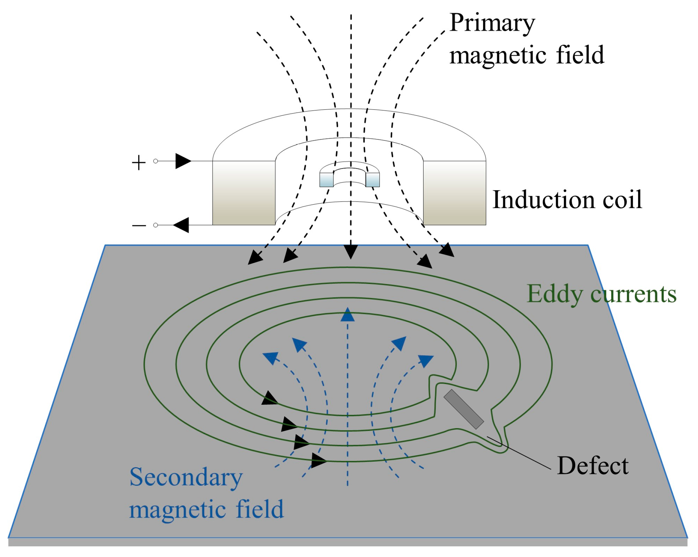
Eddy current testing (ECT) primarily operates on the principle of eddy current effects to identify external damages in conductive materials [21]. As depicted in Figure 1, when current traverses through a conductor, eddy currents are generated around it. The flow of these eddy currents is disrupted by defects, which in turn leads to a change in the coil’s impedance. By measuring the variations in impedance, it is possible to ascertain the presence of defects in the inspected object [22]. This method’s foundation intertwines with principles from crystallography. Characteristics of metal crystal structures, such as grain boundaries, crystallographic orientation, and defects, directly influence the propagation paths of magnetic flux and eddy currents [23]. These factors rooted in crystallography can result in alterations in eddy current signals, manifesting as specific disturbances caused by irregular grain boundaries or cracks [24]. Furthermore, the crystal structure dictates the electromagnetic properties of metallic materials, including distinct electrical and magnetic conductivities exhibited by different crystal structures, directly affecting the generation and propagation of eddy currents [25,26].
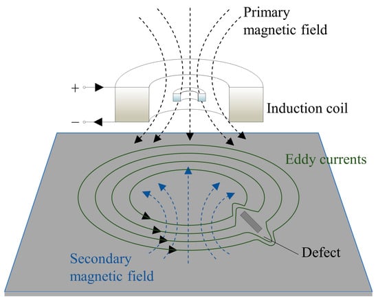
Figure 1.
Principle of the eddy current testing operation.
Consequently, ECT can be employed for the detection of various types of damage such as cracks, corrosion, and deformations. By analyzing the impedance variations, it is possible to determine the location, shape, and size of the defects. By optimizing the probe structure and signal processing algorithms, the detection sensitivity and resolution of ECT can be enhanced. For instance, Betta et al. [12] proposed an ECT probe employing a rectangular planar excitation coil and GMR sensors, whereby the optimization of probe design and rapid scanning time improved the detection capability. Additionally, Du et al. [27] utilized GMR array sensors and digital image processing techniques to further enhance the resolution of defect detection. However, there are certain drawbacks, such as sensitivity to near-surface defects and its applicability solely to conductive materials. Therefore, in practical applications, it is imperative to consider these limitations and integrate ECT with other methods for a comprehensive assessment and inspection [28].
Takanori et al. [29] proposed an eddy current magnetic signature (EC-MS) with the experimental setup shown in Figure 2, which is based on a two-dimensional vector of magnetic incremental permeability measurement. To comprehensively describe the feasibility, numerical calculation has been performed. A micro-eddy current field associated with the moving domain wall has been introduced into the Dodd and Deeds ECT approach, and a modified Helmholtz equation has been derived as follows:
where is a vector potential of component θ in the cylindrical coordinate system, is the angular frequency, is permeability, is the conductivity of the medium, and is the exciting current. Through experiments and numerical calculations, the authors reveal the phenomena and mechanisms of EC-MS, including the variation of EC-MS at different residual strain stages, its behavior under elastic stress, and its relationship with residual stress. Thus, the EC-MS method may be useful in assessing residual strain in materials, especially in understanding microscopic damage and cracking behavior in materials. This connection provides a new perspective for understanding the relationship between residual strain and microscopic cracking in materials and helps to probe deeply into the mechanisms of material damage and cracking behavior.
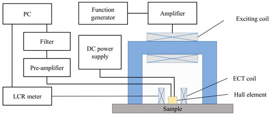
Figure 2.
Experimental setup for EC-MS method [29].
As an improvement and extension to ECT, the eddy current array (ECA) avails accurate detection and characterization of stress corrosion cracking (SCC). By employing a set of electric eddy current coils and image reconstruction algorithms, a panoramic image of the inspection area is generated, thereby facilitating accurate, high-resolution, and rapid inspection over large areas [30]. Hossein et al. [31] fabricated predefined notches and subjected the specimens to a stress corrosion environment. Through ECA inspection, the SCC defects generated on the specimens were successfully detected and characterized.
2.2. Magnetic Particle Testing
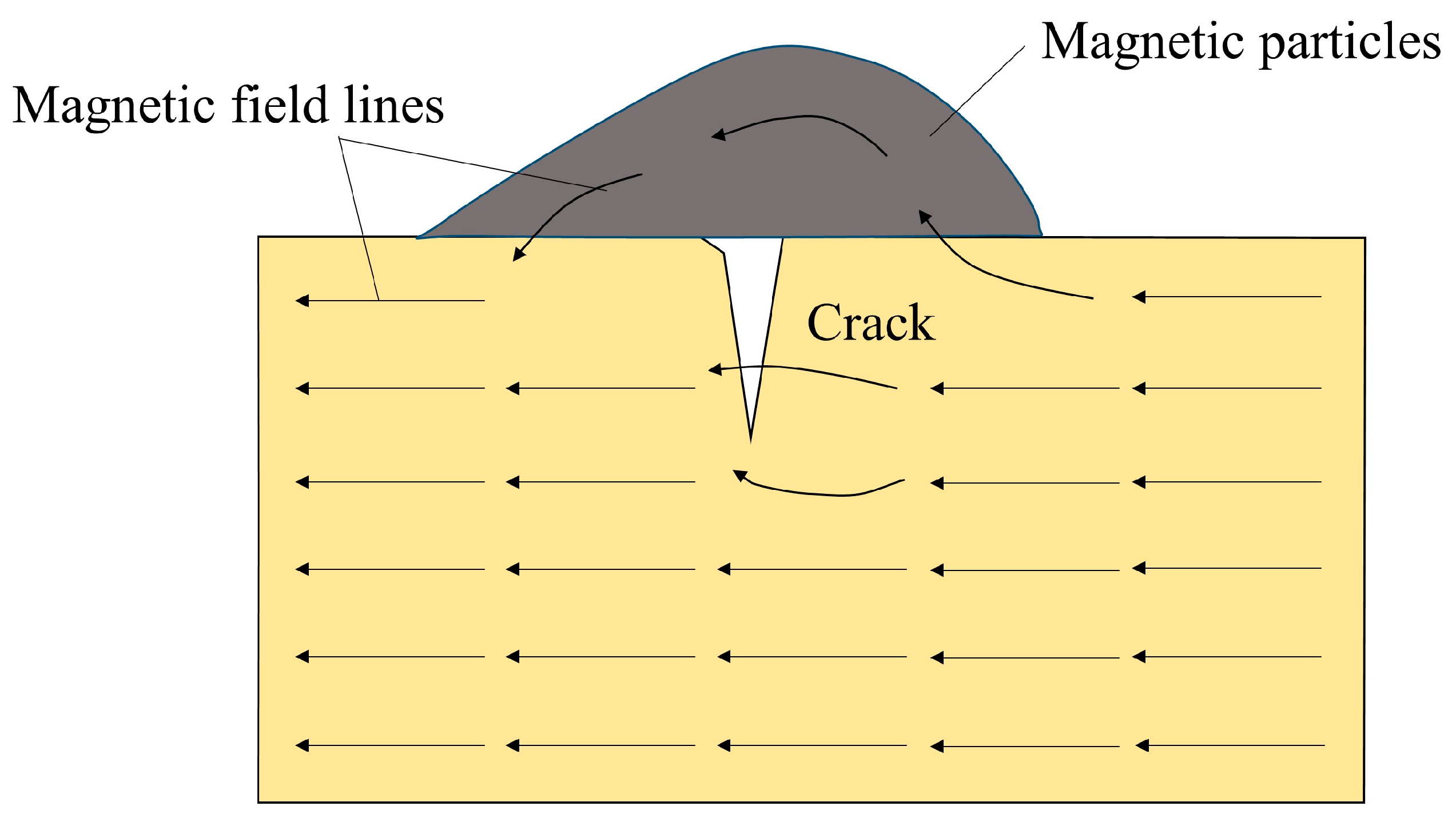
Magnetic particle testing (MPT) is primarily utilized for detecting cracks and defects in metallic materials [32]. As illustrated in Figure 3, the core principle entails magnetizing the object under inspection to create a critical magnetic field area; when cracks or defects are present, the magnetic field leaks from these areas forming a magnetic field gradient. By dispersing magnetic particles on the object’s surface, these particles aggregate at the sites of cracks or defects, forming magnetic particle indications (MPI), thereby visually delineating the location and shape of the cracks or defects [13].
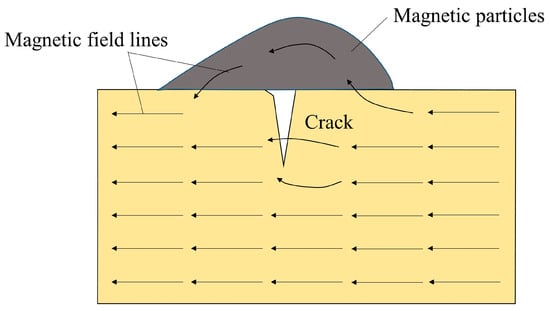
Figure 3.
Principle of magnetic particle testing operation.
However, traditional MPT requires special treatment of the magnetic particles to form visible indications, potentially leading to environmental pollution and operational complexity [14]. Chen et al. [33] proposed a method based on the three-dimensional profile measurement of MPI, which employs scanning laser triangulation technology to acquire the three-dimensional profile of the object under inspection, eliminating the need for special treatment of magnetic particles. As shown in Figure 4, the reflected laser is focused through a lens and sensed by a photodiode array, where the reflected laser deviates with the height variety of the target surface. Utilizing the optical system’s information, height variations can be calculated. This measurement technique renders the operation more straightforward and environmentally friendly, and by comparing the profile alterations before and after the addition of magnetic particles, changes induced by cracks are extracted. Furthermore, through Euclidean clustering and digital model-based fake magnetic particle indication evaluation methods, automatic crack detection is achieved.
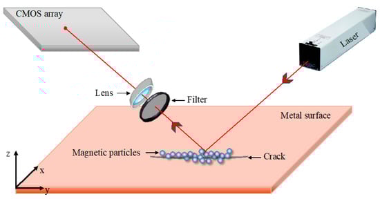
Figure 4.
Schematic diagram of scanning laser triangulation technology.
False magnetic effects may occur in magnetic particle inspection when residual magnetism or magnetic material is present on the metal surface. This phenomenon is mainly manifested as a false-positive signal due to the presence of surface magnetism [34]. Although this phenomenon stems directly from magnetic interference, the crystallographic perspective also provides another layer of explanation for the mechanism of its occurrence. Different features of the crystal structure, such as grain orientation, grain boundaries, and crystal defects, may lead to a heterogeneous distribution of residual magnetism on the metal surface [35]. This variability may become the aggregation point of magnetic regions, triggering the appearance of pseudomagnetic effects. In addition, the crystal structure also has an influence on the distribution and behavior of magnetic particles on the metal surface. Different crystal structures may lead to different aggregation and dispersion of magnetic particles on the surface, which further affects the extent and manifestation of the pseudomagnetic effect [36,37]. Kang et al. [38], on the other hand, accurately assess the likelihood of fake magnetic particle indications by computing the magnetic field distribution and evaluating the density of the normal magnetic induction intensity. Subsequently, by employing image registration and template matching techniques, the areas of fake magnetic particle indications are eliminated from the inspection results, thus achieving automatic recognition of MPI, which enhances the efficiency and accuracy of MPT and lays a significant foundation for automated MPT. Figure 5 illustrates the elimination of the false magnetic particle indication scheme. Abolfazl et al. [39] explore the reliability and sensitivity of magnetic particle nondestructive testing techniques for detecting surface cracks in welded assemblies. The sensitivity and reliability parameters of the magnetic particle NDT technique for detecting surface cracks in welded assemblies were derived. Specifically, the detection rate, maximum missed crack length, minimum detected crack length, and probabilistic detection curves for the magnetic particle NDT technique are obtained.
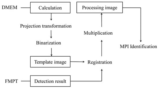
Figure 5.
Schematic of FMPI elimination [38].
2.3. Penetrant Testing
Penetrant testing (PT), also known as liquid penetrant inspection, is a nondestructive testing technique designed to detect surface open flaws such as cracks, pores, inclusions, and fatigue cracks in materials [40]. It is particularly well suited for non-magnetic metals like aluminum, magnesium, and stainless steel, as well as for various non-metallic materials [41]. The method primarily involves the application of a liquid penetrant with low surface tension to identify and reveal surface open defects on materials. The penetrant seeps into surface breaks and voids, and subsequent steps of cleaning and developer application allow the penetrant to emerge from the defects for visual or optical detection [42].
The advantages of the PT method include its simplicity of operation, cost-effectiveness, high sensitivity to minute defects, and applicability to complex geometries. However, its disadvantages may involve sensitivity to material surfaces and environmental impact. The core of this method is the use of fluorescent penetrants and ultraviolet radiation sources, enabling the detection of even the smallest defects with high visibility for easy recording of results [43]. However, PT requires thorough surface preparation and must be conducted in specific darkroom conditions, demanding a high level of skill from the operators.
Appropriate selection of ultraviolet radiation sources has a significant effect on PT optimization. Kudinov et al. [44] proposed a method for comprehensively evaluating the effectiveness of different UV radiation sources and investigated the effect of different types of UV radiation sources on the detection results. The effectiveness of various UV radiation sources has been assessed by analyzing the experimental results and the best choice is suggested to optimize the fluorescence penetration detection.
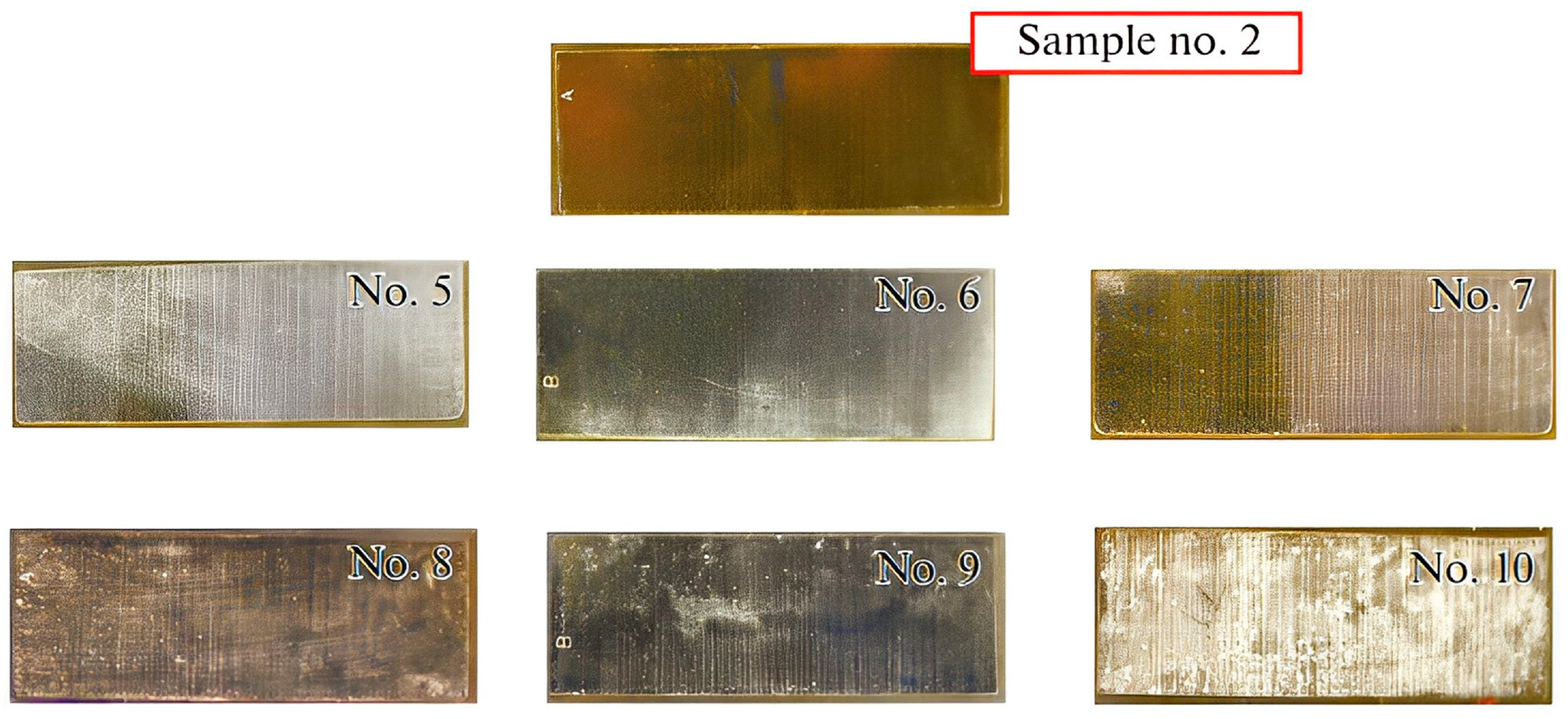
In addition, Ospennikova et al. [45] have innovated upon the conventional penetrant testing (PT) methodologies to enhance applicability in areas that are challenging to access. They have employed a concoction of powder developers characterized by elevated absorptivity and adhesion, significantly augmenting the visibility of indications on components with intricate geometries, thus bolstering the inspection’s efficiency and reliability. Notably, the three powder developer mixtures, a mixture of polyvinylpyrrolidone and magnesium oxide for sample No. 5, magnesium oxide for sample No. 6, and polyvinylpyrrolidone and zinc oxide for sample No. 7, were the most effective. These mixtures produced indicator patterns that were not only bright and high contrast but also resistant to mechanical action. As shown in Figure 6, the powder samples are firmly adsorbed onto the surface, forming developer “beads” above the defects and lying evenly on top, creating a thin, uniform white background.
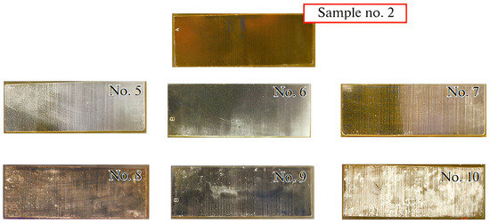
Figure 6.
Results of studying adhesion of powder developers to the surface of test sample having cracks with an opening width of 0.5 μm [45].
Furthermore, Karatay [46] introduced a more eco-friendly alternative employing bacterial suspensions as fluorescent penetrants. This approach mitigates environmental contamination, decreases operational costs, and streamlines the testing procedure. Escherichia coli labeled with fluorescein isothiocyanate (FITC-E. coli) demonstrated exceptional efficacy in the detection of fissures and other imperfections, paving the way for prospective advancements in PT.
Collectively, these refinements and innovations not only substantiate the capability of PT as a nondestructive evaluation method to effectively expose surface open flaws but also elevate its applicability in complex scenarios, concurrently diminishing its ecological footprint. These contributions reflect the ongoing evolution of PT technology and affirm its practicality and scalability in industrial settings.
3. Internal Inspection Techniques
In this section, ultrasonic testing and radiographic testing are introduced as typical nondestructive techniques for internal metal crack inspection. Ultrasonic testing leverages high-frequency acoustic waves to detect internal imperfections in materials, while radiographic testing employs penetrating radiations to expose internal structures [47,48]. Each methodology is characterized by its distinctive detection mechanism and application domain, playing an essential role in evaluating the integrity of materials and structures.
3.1. Ultrasonic Testing
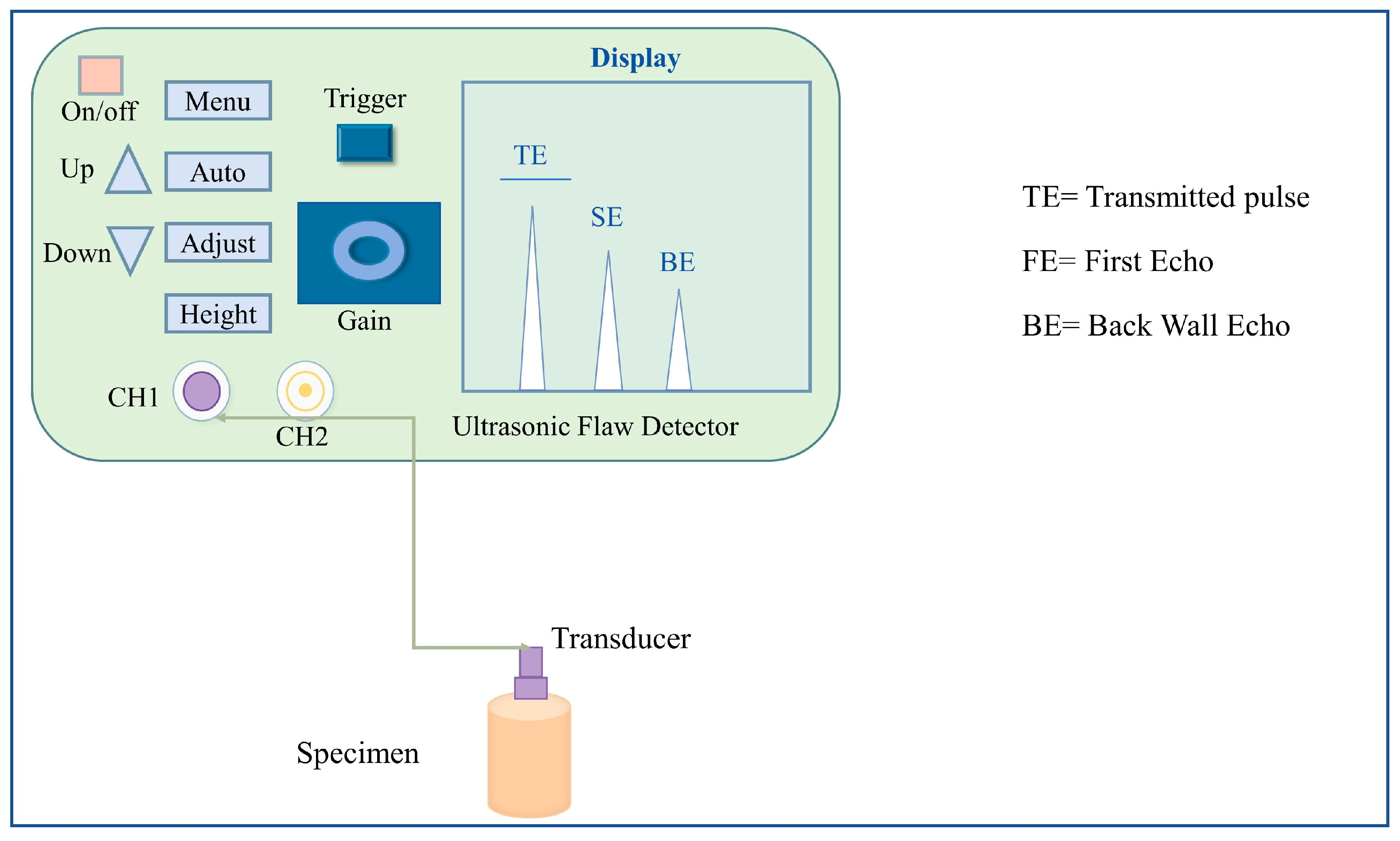
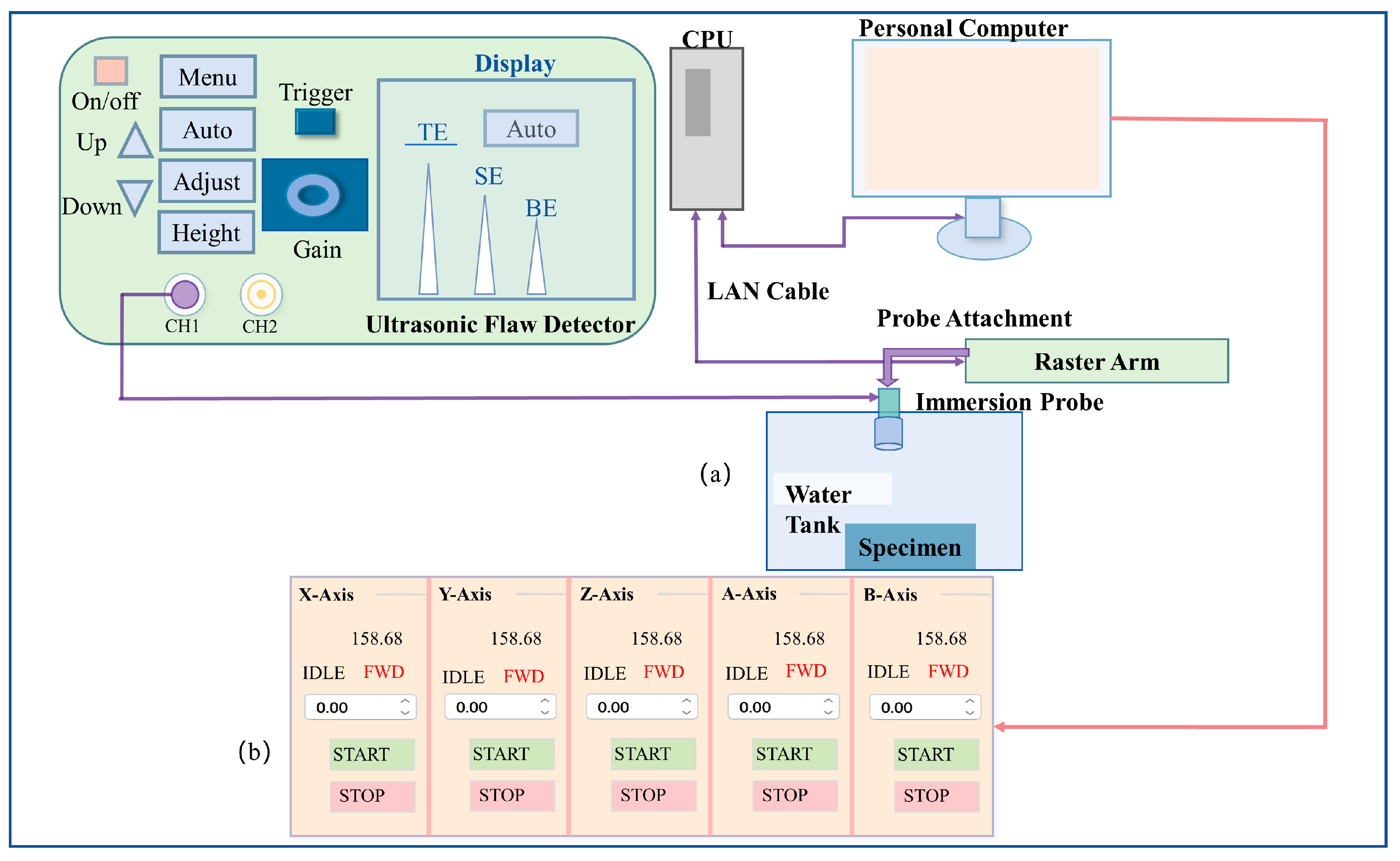
Ultrasonic testing (UT) is a pivotal nondestructive testing technique that encompasses the acquisition of a multitude of information regarding the material under examination, including its dimensions, geometric shape, and internal structure. Pulse-echo technology, a common methodology within UT, ascertains crack characteristics by measuring the time differential between the transmission and reception of ultrasonic waves [49]. Yadav et al. [50] compare contact and immersion ultrasonic techniques for dimensional measurement (thickness) on ASTM reference blocks, with experimental setups illustrated in Figure 7 and Figure 8, respectively. Using a piezoelectric broadband transducer to generate longitudinal ultrasonic waves within the reference block and recording the echoes via an ultrasonic flaw detector, it is observed that the immersion technique provides more precise material thickness measurements with lower uncertainty.
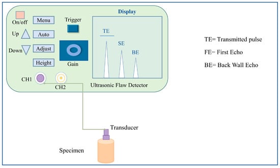
Figure 7.
The experimental setup for the ultrasonic contact method [50].
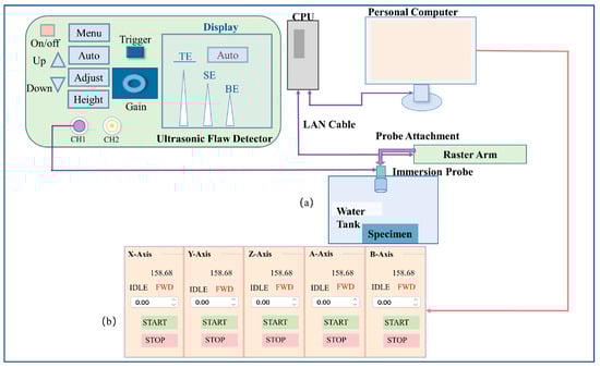
Figure 8.
(a) Experimental setup for the ultrasonic immersion method and (b) enlarged picture of developed GUI for motion control [50].
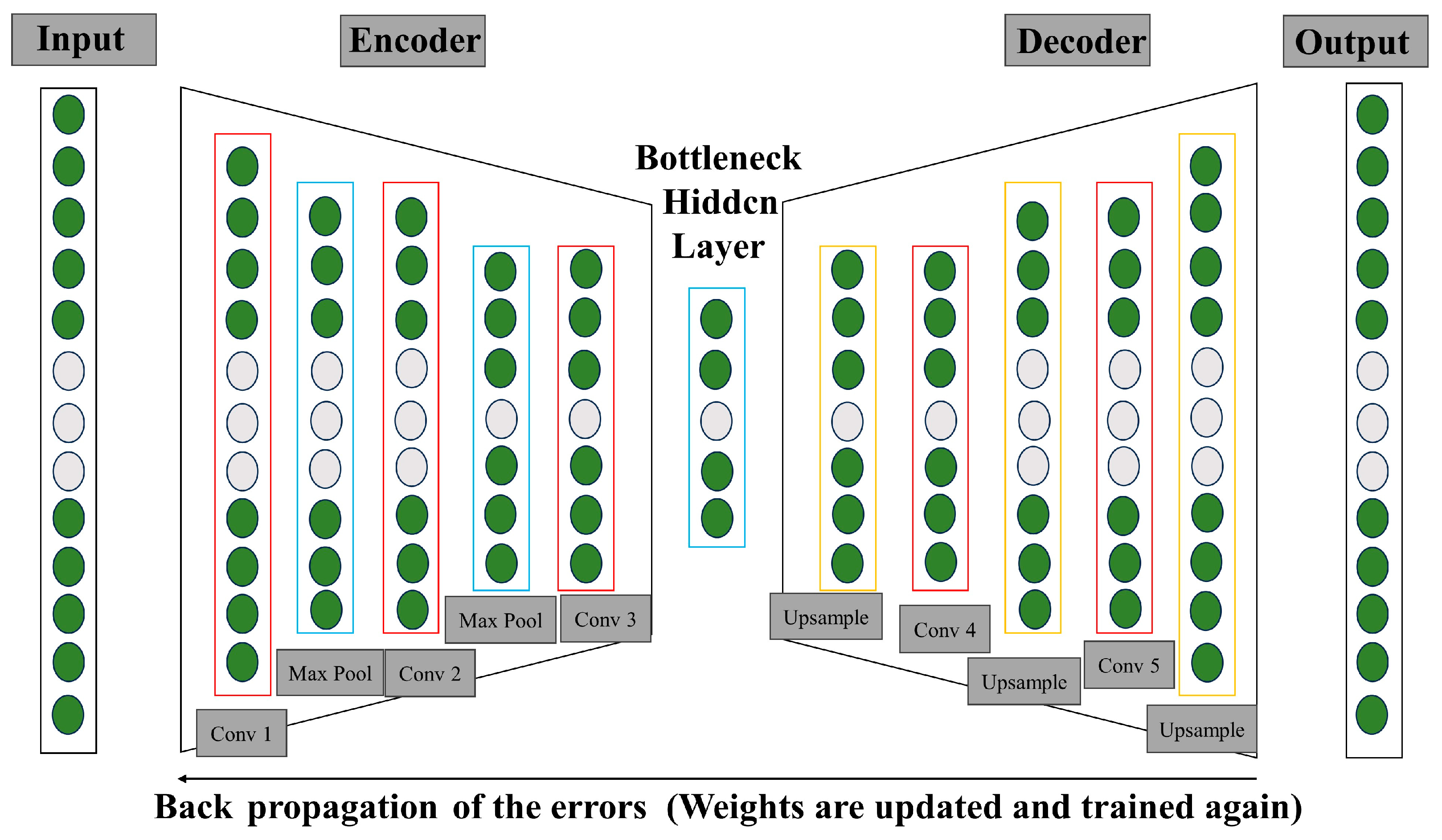
Despite UT’s wide application in structural integrity assessments, particularly in the detection of welding defects, it is not without limitations, such as susceptibility to ambient noise interference. The background signal interference generated in UT method detection is usually related to the properties of the crystal and the material characteristics. The properties of crystals affect the propagation and reflection of ultrasonic waves, thus generating background signal interference [51,52]. For example, the geometry, speed of sound, and attenuation properties of the crystal affect the propagation path and signal characteristics of the ultrasonic waves, which in turn affects the generation of the background signal and the degree of interference [53]. Lee et al. [54] have highlighted the inadequacies of conventional noise reduction methods, such as thresholding or Hilbert transformations, as shown in Figure 9, depicting the architecture of a conventional denoising autoencoder. In response, they proposed a method utilizing denoising autoencoders, a neural network-based technique for extracting target defect signals from noisy data. This involves compressing the mixed signal input via an encoder and reconstructing the compressed signal through a decoder.
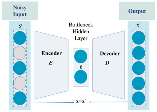
Figure 9.
Architecture of the conventional denoising autoencoder. stands for the noisy signal, for the reconstructed non-noisy version, and c represents the characteristics of the input noise signal [54].
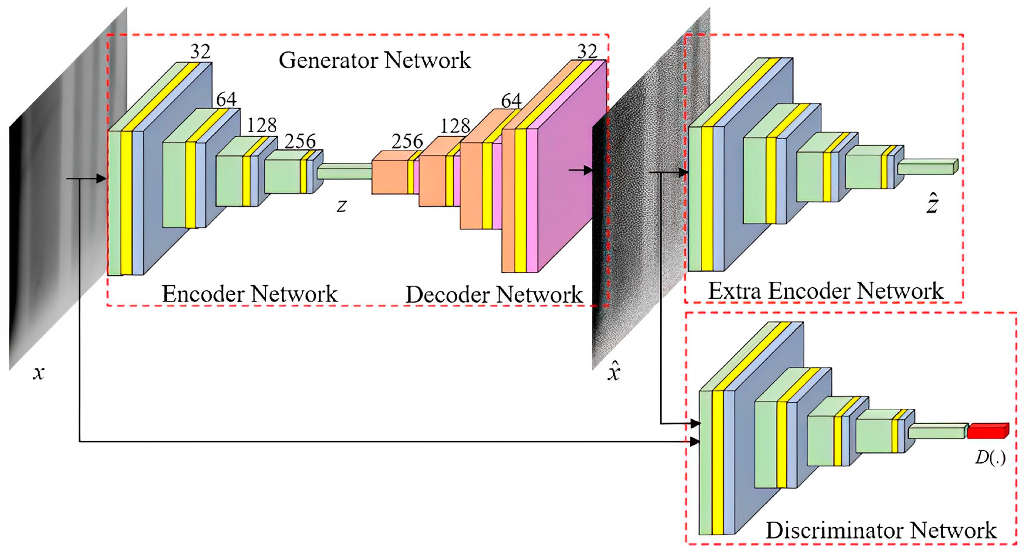
During training, the network learns to extract features of the defect signal by minimizing the difference between the reconstructed and target defect signals, illustrated in Figure 10. This artificial neural network technique demonstrates superior performance in isolating defect signals, successfully mitigating background noise and accentuating the defect signal. Further exploration by Lee et al. [55] has investigated the integration of phased array ultrasonic testing with neural networks for the acceptability assessment of welding defect dimensions. Generating and analyzing S-scan images and employing Mask R-CNN models for image training and classification, their research has not only corroborated the model’s accuracy but also enhanced detection efficiency.
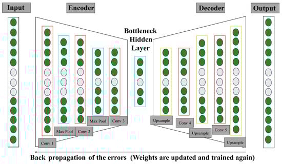
Figure 10.
The diagram of training procedure for the proposed denoising autoencoders used in Lee’s study [54].
Additionally, to augment the defect detection capabilities of ultrasonic guided wave techniques, Hwang et al. [56] employed a short-time Fourier transform for signal time–frequency analysis, extracting distinguishing features of samples with and without defects. Coupled with linear discriminant analysis for sample classification, their methodology demonstrates high accuracy in defect detection in 304 stainless steel plates, providing an effective nondestructive evaluation method for the safety assessment of such plates.
3.2. Radiographic Testing
Radiographic testing (RT) is a technique that employs X-rays or gamma rays to detect internal defects within pipelines. The challenge of this technique resides in the interference caused by scattered radiation, influenced by crystallographic elements such as grain orientation, grain boundaries, and defects, which contribute to the scattering of X-rays, resulting in imaging noise and blurring within the captured images [57,58]. These crystallographic factors induce partial deviation of X-rays from their original propagation paths, with crystal defects serving as potential scattering centers, thereby inducing random dispersion of radiation. Moreover, the spacing and orientation of the crystal lattice can further prompt diffraction effects in scattered radiation, exerting additional influence on the scattering phenomena observed [59,60,61]. To enhance the reliability of detection, it is necessary to improve the signal-to-noise ratio and contrast of the images [15]. In this regard, digital image processing algorithms, such as the total variation method, optimized neural networks, and sparse methods, are widely used for image enhancement. Effat et al. [16] have proposed the fast regularized kernel estimation (FRKE) and the modified Goldstein–Fattal method (MGFM) as examples of image enhancement techniques and compared their effectiveness. FRKE is a blind deblurring method based on prior knowledge, which iteratively reduces blur and enhances contrast, whereas MGFM estimates the blur kernel by analyzing irregularities in the image power spectrum to reconstruct a clear image. These methods aim to improve the clarity and contrast of X-ray images, enhancing the detectability of internal pipeline defects.
Chen et al. [17] combined the YOLOv4 object inspection model with RT image-based NDT techniques to improve the inspection efficiency of aero structural and engine components. A dataset is preprocessed by marking and classifying defects in RT images, including maintenance record images of civil aircraft fuselages and engines. An automatic defect detection model is constructed using deep learning and computer vision technologies, effectively elevating the level of automation in defect detection for aeronautical structures and components.
For the RT inspection of aviation engine turbine blades, traditional methods are typically semiautomatic, involving X-ray photography and industrial view boxes. However, these methods are subject to subjective judgment, which may reduce detection accuracy and efficiency, and become particularly prone to omissions and false detections when the workload increases. With the advancement of deep learning technologies, automatic nondestructive testing has become a research focus. Wang et al. [62] underscore the process of automatic defect detection in X-ray images based on deep learning. Figure 11 displays the overall network model including data preparation, model selection, training, evaluation, and the final defect detection. This process identifies defects within X-ray images through deep learning models, enhancing the precision and efficiency of detection.
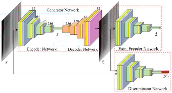
Figure 11.
Overall network structure of the defect detection model for turbine blades [62].
In the field of NDT, each methodology possesses unique advantages, yet may also exhibit certain limitations contingent upon the application. Five distinct inspection techniques have been discussed, with Table 1 providing a summary of these technologies, thereby laying the groundwork for a discussion on integrating these methods into a comprehensive, multifaceted detection strategy.

Table 1.
Advantages and limitations of NDT testing techniques for surface and internal defects.
In practical nondestructive testing applications, it is of great significance to select the appropriate method, which requires careful consideration of material properties, the nature and orientation of potential defects, part geometry, and the overall safety and cost-effectiveness of the inspection process. These factors dictate the suitability and effectiveness of each NDT technique and acknowledging their interplay is crucial for accurate assessments. This understanding sets the stage for multi-factor NDT methods, where combining techniques can compensate for individual limitations and provide a more robust evaluation of component integrity.
In the subsequent sections, we delve into the principles and applications of multi-factor NDT methods, illustrating how they leverage the complementary nature of traditional NDT techniques to achieve superior inspection outcomes.
4. Multifactorial Detection Method
In the realm of nondestructive testing, reliance on a solitary technique often encounters constraints in detection scope and sensitivity. For instance, UT is proficient at identifying internal material defects yet demonstrates limited capacity in detecting surface or subsurface cracks. Conversely, ECT exhibits commendable sensitivity to surface flaws but is inadequate for probing deeper defects. Furthermore, the precision of these modalities is substantially compromised under high-temperature conditions or in the presence of coatings [63]. Consequently, there is a burgeoning interest among researchers to harness the synergistic potential of multiple inspection technologies, aiming to capitalize on the distinct advantages of each to augment the thoroughness and accuracy of defect detection.
Shen et al. [64] have devoted their efforts to addressing the shortcomings inherent to conventional electromagnetic acoustic testing (EMAT) and pulsed eddy current testing (PECT) methodologies. Historically applied in isolation, these techniques have not only impeded detection efficiency but also exacerbated the complexity of testing. A novel amalgamated technique has been proposed that exploits the partial PECT information intrinsic to the signals produced by EMAT. By employing precise waveform analysis and signal processing, this approach enables the concurrent evaluation of surface and subsurface anomalies in conductive materials such as aluminum plates, as illustrated in Figure 12, which delineates the constituent elements of the experimental EMAT/PECT system. By advancing numerical modeling and refining signal processing algorithms, this method achieves efficacious integration of EMAT and PECT signals, surmounting the inefficiencies and intricacies of operation.
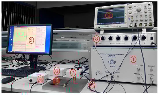
Figure 12.
EMAT/PECT experiment system (1: RAM-5000; 2: all connections; 3: computer system and software interface; 4: duplexer; 5: probe; 6: preamplifier; 7: signal selector; 8: filter; 9: oscilloscope) [64].
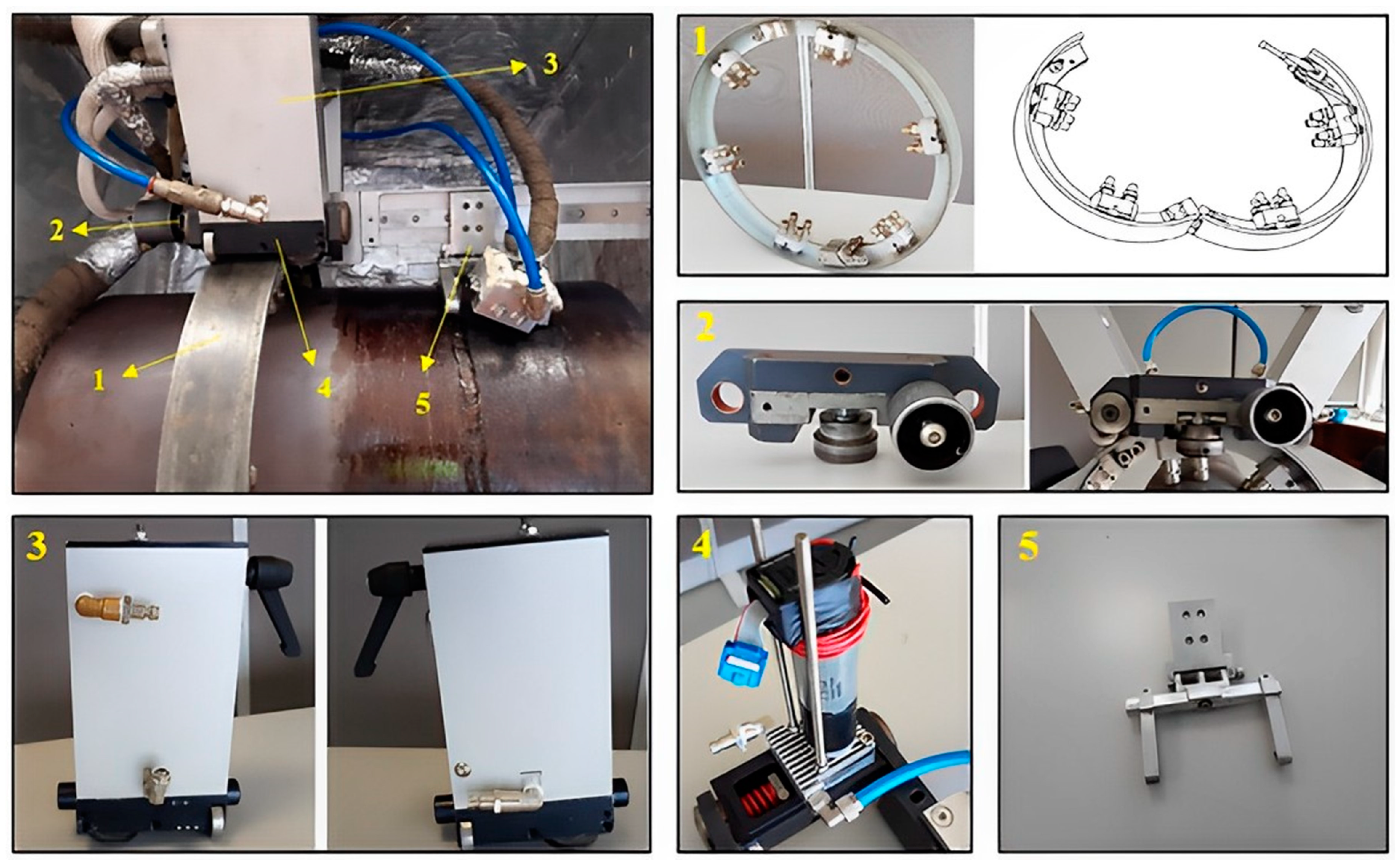
David et al. [65] have conceived an automated inspection apparatus, the quintessential components of which are illustrated in Figure 13. This system amalgamates ultrasonic and eddy current inspection modalities and is designed to facilitate simultaneous ultrasonic and eddy current examinations through the incorporation of scanners on rail guiders. This integrative scheme is especially apt for high-temperature operational settings, mitigating operator exposure to high-temperature components, thus enhancing safety. Moreover, it broadens the inspection scope and augments the likelihood of flaw detection by melding disparate inspection technologies.

Figure 13.
Automated inspection system elements: 1—orbital guide around the pipe; 2—quick tightening joint; 3—air-cooled housing; 4—water-cooled base plate; 5—probe holder [65].
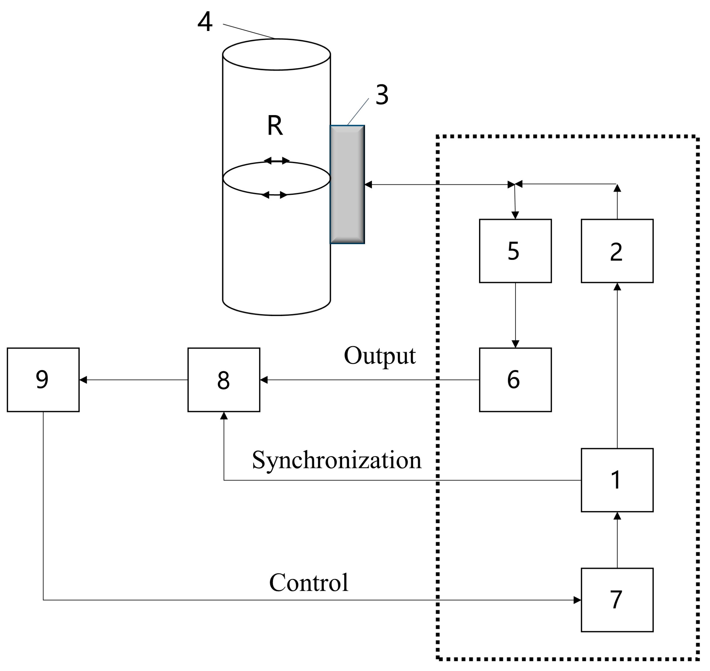
Aleshin et al. [66] have scrutinized the constraints of conventional ultrasonic inspections and magnetic particle testing in discerning surface cracks within weld joints, particularly those obscured by anticorrosive coatings. This methodology integrates phased array ultrasonic technology with eddy current testing, enabling the detection of fissures without necessitating the removal of anticorrosive layers. The efficacy hinges on the enhanced precision afforded by phased array ultrasonic technology, complemented by eddy current testing to corroborate the existence of cracks, thus permitting an assessment of the cracks without stripping the coating. Murav’eva et al. [67] have promoted an advanced multi-technique nondestructive testing strategy, facilitating a more comprehensive inspection of defects within the connectors of pumps and compressors, as depicted in Figure 14. The incorporation of magnetic particle, eddy current, and ultrasonic shadow testing methodologies enables the detection of surface, subsurface, and certain in-depth flaws. The magnetic particle approach yields surface defect detection, eddy current testing elucidates the depth and orientation of cracks, and ultrasonic shadow testing leverages Rayleigh waves to detect minute apertures and shallow defects. This multi-modal approach substantially enhances the efficiency and precision of detection, particularly within the convoluted milieu of industrial settings.
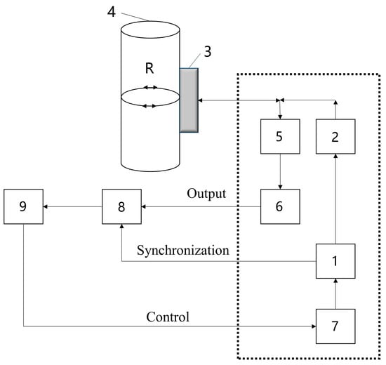
Figure 14.
Block diagram: 1—synchro pulse generator; 2—probing pulse generator; 3—attached two-channel EMA transducer; 4—test sample of workpiece; 5—bandpass filter; 6—high-frequency amplifier; 7—control board for synchro pulse generator and channels; 8—analog-to-digital converter; 9—personal computer with PRINTs software [67].
These investigations highlight the significant advantages of integrating multiple nondestructive testing methodologies, thereby greatly improving the limitations of singular approaches and significantly contributing to the enhancement of safety evaluations for industrial apparatuses and structures. Future research endeavors will continue to refine these integrated methods to better suit various environmental conditions and elevate the automation and intelligence quotient of the testing processes, aiming for more efficacious and accurate detection outcomes.
5. Conclusions
In summary, it is recognized that the field of NDT is undergoing significant technological advancements, particularly within internal inspection methodologies such as ultrasonic and radiographic testing. The integration of advanced image processing technologies and data analytics tools has led to enhanced precision and resolution in defect detection. External inspection techniques like eddy current testing, magnetic particle testing, and dye penetrant inspection are also harnessing the power of the Internet of Things and automation to improve operational efficiency and real-time monitoring capabilities. Moreover, the emergence of multifactorial inspection approaches, which combine multiple testing techniques to assess the integrity of materials or structures, represents a crucial trend in NDT. This trend significantly elevates the comprehensiveness and reliability of inspections by integrating diverse signals and data sources.
Nonetheless, challenges persist, including the need to inspect more complex structures and novel materials, increasing the portability of inspection devices, and reducing inspection cycle times. Concurrently, as the application of new crystalline materials becomes more widespread, NDT techniques face the challenge of adapting to the unique properties of these materials. For instance, the anisotropy of crystalline materials may affect the propagation path in ultrasonic testing and the attenuation characteristics in radiographic testing, necessitating the development of more advanced algorithms and calibration techniques to ensure accuracy in detection. Future directions may include optimizing inspection methods for specific crystal structures and employing artificial intelligence and machine learning technologies to tackle the challenges posed by the complexity of crystalline materials in data interpretation. Furthermore, the development of multimodal NDT systems, which can combine the advantages of different technologies, will be crucial for effectively addressing the inspection challenges of crystalline materials. Therefore, the future development of NDT technologies will need to focus not only on enhancing the portability of devices and optimizing inspection cycles but also on improving the recognition capabilities for the characteristics of crystalline materials, ensuring that structural safety is maintained while adapting to the evolution of emerging material technologies.
Author Contributions
Resources, X.S. and Z.L.; writing—original draft preparation, X.L.; writing—review and editing, X.S. and X.L.; visualization, J.G., Y.L. and J.Q.; supervision, Z.L.; funding acquisition, X.S. All authors have read and agreed to the published version of the manuscript.
Funding
This work was supported by Natural Science Research Projects of Anhui Universities (KJ2021A0428), Introduction of Talent Research Start-up Fund of Anhui University of Science and Technology (2021yjrc49), Anhui Training Program of Innovation and Entrepreneurship for Undergraduates (202210361074), Anhui Provincial Natural Science Foundation (2208085QE171), and Anhui International Joint Research Center for Nano Carbon-based Materials and Environmental Health (NCMEH2022Y01).
Data Availability Statement
No new data were created or analyzed in this study. Data sharing is not applicable to this article.
Conflicts of Interest
The authors declare no conflict of interest.
References
- Zhao, Z. Review of Non-destructive Testing Methods for Defect Detection of Ceramics. Ceram. Int. 2021, 47, 4389–4397. [Google Scholar] [CrossRef]
- Silva, M.I.; Malitckii, E.; Santos, T.G.; Vilaça, P. Review of Conventional and Advanced Non-destructive Testing Techniques for Detection and Characterization of Small-scale Defects. Prog. Mater. Sci. 2023, 138, 101155. [Google Scholar] [CrossRef]
- Jin, Z.-H.; Fu, Y. Residual Strength of Metal Particulate Reinforced Ceramics with Parallel Cracks. Mater. Sci. Eng. A 2009, 527, 252–257. [Google Scholar] [CrossRef]
- Deng, A.; Chen, H.; Zhang, Y.; Liu, Y.; Yang, X.; Zhang, Z.; Zhang, B.; He, D. Prediction of the Influence of Welding Metal Composition on Solidification Cracking of Laser Welded Aluminum Alloy. Mater. Today Commun. 2023, 35, 105556. [Google Scholar] [CrossRef]
- Jiang, F.; Liu, S.; Xin, S.; Zhang, H. Electromagnetic Nondestructive Testing Model and Surface Magnetic Field Analysis for Circumferential Cracks on Metal Rod. J. Nondestruct. Eval. Diagn. Progn. Eng. Syst. 2019, 2, 044501. [Google Scholar] [CrossRef]
- Abou-Khousa, M.A.; Rahman, M.S.U.; Donnell, K.M.; Al Qaseer, M.T. Detection of Surface Cracks in Metals Using Microwave and Millimeter-Wave Nondestructive Testing Techniques—A Review. IEEE Trans. Instrum. Meas. 2023, 72, 1–18. [Google Scholar] [CrossRef]
- Wang, D.; Yin, J.; Wu, H.; Ge, B. Method for Detecting Internal Cracks in Joints of Composite Metal Materials Based on Dual-channel Feature Fusion. Opt. Laser Technol. 2023, 162, 109263. [Google Scholar] [CrossRef]
- Tanaka, K.; Mura, T. A Dislocation Model for Fatigue Crack Initiation. J. Appl. Mech. 1981, 48, 97–103. [Google Scholar] [CrossRef]
- Navarro, A.; Rios, E.R.D. A Model for Short Fatigue Crack Propagation with an Interpretation of the Short-long Crack Transition. Fatigue Fract. Eng. Mater. Struct. 1987, 10, 169–186. [Google Scholar] [CrossRef]
- Zhang, L.; Wang, Z.; Wang, L.; Zhang, Z.; Chen, X.; Meng, L. Machine Learning-based Real-time Visible Fatigue Crack Growth Detection. Digit. Commun. Netw. 2021, 7, 551–558. [Google Scholar] [CrossRef]
- Yao, Y.; Tung, S.-T.E.; Glisic, B. Crack Detection and Characterization Techniques-An Overview. Struct. Control Health Monit. 2014, 21, 1387–1413. [Google Scholar] [CrossRef]
- Betta, G.; Ferrigno, L.; Laracca, M.; Burrascano, P.; Ricci, M. Optimized Complex Signals for Eddy Current Testing. In Proceedings of the 2014 IEEE International Instrumentation and Measurement Technology Conference (I2MTC) Proceedings, Montevideo, Uruguay, 12–15 May 2014. [Google Scholar] [CrossRef]
- Pydi, H.P.; Pradeep, A.; Vijayakumar, S.; Srinivasan, R. Examination of Various Weld Process Parameters in MIG Welding of Carbon Steel on Weld Quality Using Radiography & Magnetic Particle Testing. Mater. Today Proc. 2022, 62, 1909–1912. [Google Scholar] [CrossRef]
- Chen, Y.; Feng, B.; Kang, Y.; Liu, B.; Wang, S.; Duan, Z. A Novel Thermography-Based Dry Magnetic Particle Testing Method. IEEE Trans. Instrum. Meas. 2022, 71, 9505309. [Google Scholar] [CrossRef]
- Yahaghi, E.; Garcia, J.A.M.; Movafeghi, A. Fracture and Internal Structure Detection of Ceramic Objects Using Improved Digital Radiography Images. J. Cult. Herit. 2020, 44, 152–162. [Google Scholar] [CrossRef]
- Yahaghi, E.; Movafeghi, A.; Mirzapour, M. Welded Pipe Defect Detection Enhancement Using Regularized Kernel Estimation-Based Image Processing in Radiographic Testing. Russ. J. Nondestruct. Test. 2022, 58, 760–767. [Google Scholar] [CrossRef]
- Chen, Z.-H.; Juang, J.-C. YOLOv4 Object Detection Model for Nondestructive Radiographic Testing in Aviation Maintenance Tasks. AIAA J. 2021, 60, 526–531. [Google Scholar] [CrossRef]
- Lin, Y.; Ma, J.; Wang, Q.; Sun, D.-W. Applications of Machine Learning Techniques for Enhancing Nondestructive Food Quality and Safety Detection. Crit. Rev. Food Sci. Nutr. 2023, 63, 1649–1669. [Google Scholar] [CrossRef]
- Vavilov, V.P. Thermal Nondestructive Testing: Development of Conventional Directions and New Trends (A Review). Russ. J. Nondestruct. Test. 2023, 59, 702–723. [Google Scholar] [CrossRef]
- Xu, Y.; Xu, K.; Wang, H.; Zhao, L.; Tian, J.; Xie, Y.; Liu, J. Research Progress on Magnetic Memory Nondestructive Testing. J. Magn. Magn. Mater. 2023, 565, 170245. [Google Scholar] [CrossRef]
- Angani, C.S.; Ramos, H.G.; Ribeiro, A.L.; Rocha, T.J. Evaluation of Transient Eddy Current Oscillations Response for Thickness Measurement of Stainless Steel Plate. Measurement 2016, 90, 59–63. [Google Scholar] [CrossRef]
- Vacher, F.; Alves, F.; Gilles-Pascaud, C. Eddy Current Nondestructive Testing with Giant Magneto-impedance Sensor. NDT E Int. 2007, 40, 439–442. [Google Scholar] [CrossRef]
- Stojakovic, D. Electron Backscatter Diffraction in Materials Characterization. Process. Appl. Ceram. 2012, 6, 1–13. [Google Scholar] [CrossRef]
- Nazrin, S.N.; Da Silva, M.P.; Li, M.S.; Marega, E., Jr. Activation Energy and Its Fluctuations at Grain Boundaries of Er3+:BaTiO3 Perovskite Thin Films: Effect of Doping Concentration and Annealing Temperature. Vacuum 2021, 194, 110562. [Google Scholar] [CrossRef]
- Cao, M.; Wang, X.; Zhang, M.; Shu, J.; Cao, W.; Yang, H.; Fang, X.; Yuan, J. Electromagnetic Response and Energy Conversion for Functions and Devices in Low-dimensional Materials. Adv. Funct. Mater. 2019, 29, 1807398. [Google Scholar] [CrossRef]
- Lv, H.; Yang, Z.; Pan, H.; Wu, R. Electromagnetic Absorption Materials: Current Progress and New Frontiers. Prog. Mater. Sci. 2022, 127, 100946. [Google Scholar] [CrossRef]
- Du, W.; Nguyen, H.; Dutt, A.; Scallion, K. Design of a GMR Sensor Array System for Robotic Pipe Inspection. In Proceedings of the 2010 IEEE Sensors, Waikoloa, HI, USA, 1–4 November 2010. [Google Scholar] [CrossRef]
- Angani, C.S.; Ramos, H.G.; Ribeiro, A.L.; Rocha, T.J.; Baskaran, P. Lift-Off Point of Intersection Feature in Transient Eddy-Current Oscillations Method to Detect Thickness Variation in Stainless Steel. IEEE Trans. Magn. 2016, 52, 6201408. [Google Scholar] [CrossRef]
- Matsumoto, T.; Uchimoto, T.; Takagi, T.; Dobmann, G.; Ducharne, B.; Oozono, S.; Yuya, H. Investigation of Electromagnetic Nondestructive Evaluation of Residual Strain in Low Carbon Steels Using the Eddy Current Magnetic Signature (EC-MS) Method. J. Magn. Magn. Mater. 2019, 479, 212–221. [Google Scholar] [CrossRef]
- Wan, B.; Hu, B.; Chen, X. Analytical Solutions for Flexible Circular Spiral Eddy Current Array Coils Inside a Conductive Tube Under Different Operation Modes. NDT E Int. 2022, 131, 102693. [Google Scholar] [CrossRef]
- Taheri, H.; Jones, C.; Taheri, M. Assessment and Detection of Stress Corrosion Cracking by Advanced Eddy Current Array Nondestructive Testing and Material Characterization. J. Nat. Gas Sci. Eng. 2022, 102, 104568. [Google Scholar] [CrossRef]
- Kasai, N.; Takada, A.; Fukuoka, K.; Aiyama, H.; Hashimoto, M. Quantitative Investigation of a Standard Test Shim for Magnetic Particle Testing. NDT E Int. 2011, 44, 421–426. [Google Scholar] [CrossRef]
- Chen, Y.; Feng, B.; Kang, Y.; Cai, X.; Wang, S.; Li, Y.; Duan, Z. Automatic Crack Identification Using a Novel 3D Profilometry-based Magnetic Particle Testing Method. Mech. Syst. Signal Process. 2023, 202, 110720. [Google Scholar] [CrossRef]
- Rahman, S.; Torres, J.F.; Khan, A.R.; Lu, Y. Recent Developments in van der Waals Antiferromagnetic 2D Materials: Synthesis, Characterization, and Device Implementation. ACS Nano 2021, 15, 17175–17213. [Google Scholar] [CrossRef] [PubMed]
- Zou, J.; Gaber, Y.; Voulazeris, G.; Li, S.; Vazquez, L.; Liu, L.-F.; Yao, M.-Y.; Wang, Y.-J.; Holynski, M.; Bongs, K.; et al. Controlling the Grain Orientation during Laser Powder Bed Fusion to Tailor the Magnetic Characteristics in a Ni-Fe Based Soft Magnet. Acta Mater. 2018, 158, 230–238. [Google Scholar] [CrossRef]
- Vahidi, H.; Syed, K.; Guo, H.; Wang, X.; Wardini, J.L.; Martinez, J.; Bowman, W.J. A Review of Grain Boundary and Heterointerface Characterization in Polycrystalline oxides by (Scanning) Transmission Electron Microscopy. Crystals 2021, 11, 878. [Google Scholar] [CrossRef]
- Shin, S.; Schafer, R.; De Cooman, B.C. Grain Boundary Penetration by Lancet Domains in Fe-3% Si Grain-oriented Steel. IEEE Trans. Magn. 2010, 46, 3574–3581. [Google Scholar] [CrossRef]
- Chen, Y.; Kang, Y.; Feng, B.; Li, Y.; Cai, X.; Wang, S. Automatic Defect Identification in Magnetic Particle Testing Using a Digital Model Aided De-noising Method. Measurement 2022, 198, 111427. [Google Scholar] [CrossRef]
- Zolfaghari, A.; Zolfaghari, A.; Kolahan, F. Reliability and Sensitivity of Magnetic Particle Nondestructive Testing in Detecting the Surface Cracks of Welded Components. Nondestruct. Test. Eval. 2018, 33, 290–300. [Google Scholar] [CrossRef]
- Delenkovsky, N.V.; Gnusin, A.B. Estimating the Depth of Surface Flaws by Penetrant Testing. Russ. J. Nondestruct. Test. 2017, 53, 231–235. [Google Scholar] [CrossRef]
- Sudagar, J.; Lian, J.; Sha, W. Electroless Nickel, Alloy, Composite and Nano Coatings—A Critical Review. J. Alloy. Compd. 2013, 571, 183–204. [Google Scholar] [CrossRef]
- Lai, W.W.-L.; Dérobert, X.; Annan, P. A Review of Ground Penetrating Radar Application in Civil Engineering: A 30-Year Journey from Locating and Testing to Imaging and Diagnosis. NDT E Int. 2018, 96, 58–78. [Google Scholar] [CrossRef]
- Glazkov, Y.A. On the Quality of Examination Questions on Penetrant Testing. Russ. J. Nondestruct. Test. 2011, 47, 334–342. [Google Scholar] [CrossRef]
- Kudinov, I.I.; Golovkov, A.N.; Shishkin, P.A.; Skorobogatko, D.S.; Andreev, A.I.; Generalov, A.S. Evaluating the Efficiency of Using Ultraviolet Radiation Sources in Carrying Out Fluorescent Penetrant Testing. Russ. J. Nondestruct. Test. 2022, 58, 57–69. [Google Scholar] [CrossRef]
- Ospennikova, O.G.; Kudinov, I.I.; Golovkov, A.N.; Kulichkova, S.I.; Skorobogat’ko, D.S. Research of Defectoscopic Properties of Powder Compositions for Increasing Efficiency and Reliability of Penetrant Testing of Complex Shaped Parts. Russ. J. Nondestruct. Test. 2020, 56, 291–297. [Google Scholar] [CrossRef]
- Kutman, M.K.; Muftuler, F.Z.B.; Harmansah, C.; Guldu, O.K. Use of Bacteria as Fluorescent Penetrant for Penetrant Testing (PT). J. Nondestruct. Eval. 2020, 39, 15. [Google Scholar] [CrossRef]
- da Silva, R.R.; Calôba, L.P.; Siqueira, M.H.; Rebello, J.M. Pattern Recognition of Weld Defects Detected by Radiographic Test. NDT E Int. 2004, 37, 461–470. [Google Scholar] [CrossRef]
- Lu, S.; Wang, X.; Teng, L.; Zhang, J.; Zhou, Z.; Tong, Z.; Shao, H.; Men, X. Finite Element Analysis and Experimental Investigation of Ultrasonic Testing of Internal Defects in SiCp/Al Composites. Ceram. Int. 2022, 48, 5972–5982. [Google Scholar] [CrossRef]
- Li, H.; Pan, Q.; Zhang, X.; An, Z. An Approach to Size Sub-Wavelength Surface Crack Measurements Using Rayleigh Waves Based on Laser Ultrasounds. Sensors 2020, 20, 5077. [Google Scholar] [CrossRef]
- Yadav, K.; Yadav, S.; Dubey, P.K. A Comparative Study of Ultrasonic Contact and Immersion Method for Dimensional Measurements. MAPAN 2021, 36, 319–324. [Google Scholar] [CrossRef]
- Zhu, Y.-K.; Tian, G.-Y.; Lu, R.-S.; Zhang, H. A Review of Optical NDT Technologies. Sensors 2011, 11, 7773–7798. [Google Scholar] [CrossRef]
- Pierce, S.; Culshaw, B.; Philp, W.; Lecuyer, F.; Farlow, R. Broadband Lamb Wave Measurements in Aluminium and Carbon/Glass Fibre Reinforced Composite Materials Using Non-contacting Laser Generation and Detection. Ultrasonics 1997, 35, 105–114. [Google Scholar] [CrossRef]
- Biagi, E.; Margheri, F.; Menichelli, D. Efficient Laser-ultrasound Generation by Using Heavily Absorbing Films as Targets. IEEE Trans. Ultrason. Ferroelectr. Freq. Control 2001, 48, 1669–1680. [Google Scholar] [CrossRef] [PubMed]
- Lee, S.-E.; Park, J.; Kim, H.-J.; Song, S.-J. Extraction of Flaw Signals from the Mixed 1-D Signals by Denoising Autoencoder. Appl. Sci. 2023, 13, 3534. [Google Scholar] [CrossRef]
- Lee, S.-E.; Park, J.; Yeom, Y.-T.; Kim, H.-J.; Song, S.-J. Sizing-Based Flaw Acceptability in Weldments Using Phased Array Ultrasonic Testing and Neural Networks. Appl. Sci. 2023, 13, 3204. [Google Scholar] [CrossRef]
- Hwang, Y.-I.; Seo, M.-K.; Oh, H.G.; Choi, N.; Kim, G.; Kim, K.-B. Detection and Classification of Artificial Defects on Stainless Steel Plate for a Liquefied Hydrogen Storage Vessel Using Short-Time Fourier Transform of Ultrasonic Guided Waves and Linear Discriminant Analysis. Appl. Sci. 2022, 12, 6502. [Google Scholar] [CrossRef]
- Chen, Q.; Dwyer, C.; Sheng, G.; Zhu, C.; Li, X.; Zheng, C.; Zhu, Y. Imaging Beam-sensitive Materials by Electron Microscopy. Adv. Mater. 2020, 32, 1907619. [Google Scholar] [CrossRef]
- Orlova, E.V.; Saibil, H.R. Structural Analysis of Macromolecular Assemblies by Electron Microscopy. Chem. Rev. 2011, 111, 7710–7748. [Google Scholar] [CrossRef]
- Shen, G.; Mao, H.K. High-Pressure Studies with X-rays Using Diamond Anvil Cells. Rep. Prog. Phys. 2016, 80, 016101. [Google Scholar] [CrossRef]
- Lyu, Z.; Yao, L.; Chen, W.; Kalutantirige, F.C.; Chen, Q. Electron Microscopy Studies of Soft Nanomaterials. Chem. Rev. 2023, 123, 4051–4145. [Google Scholar] [CrossRef]
- Wang, Z.; Dujardin, C.; Freeman, M.S.; Gehring, A.E.; Hunter, J.F.; Lecoq, P.; Liu, W.; Melcher, C.L.; Morris, C.L.; Nikl, M.; et al. Needs, Trends, and Advances in Scintillators for Radiographic Imaging and Tomography. IEEE Trans. Nucl. Sci. 2023, 70, 1244–1280. [Google Scholar] [CrossRef]
- Wang, D.; Xiao, H.; Wu, D. Application of Unsupervised Adversarial Learning in Radiographic Testing of Aeroengine Turbine Blades. NDT E Int. 2023, 134, 102766. [Google Scholar] [CrossRef]
- Mao, X.; Lei, Y. Thickness Measurement of Metal Pipe Using Swept-frequency Eddy Current Testing. NDT E Int. 2016, 78, 10–19. [Google Scholar] [CrossRef]
- Xie, S.; Yang, S.; Tian, M.; Zhao, R.; Chen, Z.; Zheng, Y.; Uchimoto, T.; Takagi, T. A Hybrid Nondestructive Testing Method of Pulsed Eddy Current Testing and Electromagnetic Acoustic Transducer Techniques Based on Wavelet Analysis. NDT E Int. 2023, 138, 102900. [Google Scholar] [CrossRef]
- Santos, D.; Machado, M.A.; Monteiro, J.; Sousa, J.P.; Proença, C.S.; Crivellaro, F.S.; Rosado, L.S.; Santos, T.G. Non-Destructive Inspection of High Temperature Piping Combining Ultrasound and Eddy Current Testing. Sensors 2023, 23, 3348. [Google Scholar] [CrossRef] [PubMed]
- Aleshin, N.P.; Mogilner, L.Y.; Krysko, N.V.; Pridein, O.A.; Idrisov, M.T.; Kusyy, A.G. Assessing Reliability of Testing Welded Joints of Steel Tank Walls Using Ultrasonic and Eddy Current Methods. Russ. J. Nondestruct. Test. 2022, 58, 769–778. [Google Scholar] [CrossRef]
- Murav’eva, O.V.; Muraviev, M.A.; Sintsov, M.A.; Volkova, L.V. Detecting Flaws in Pumping-Compressor Pipe Couplings by Magnetic, Eddy Current, and Ultrasonic Multiple-Shadow Testing Methods. Russ. J. Nondestruct. Test. 2022, 58, 248–258. [Google Scholar] [CrossRef]


Disclaimer/Publisher’s Note: The statements, opinions and data contained in all publications are solely those of the individual author(s) and contributor(s) and not of MDPI and/or the editor(s). MDPI and/or the editor(s) disclaim responsibility for any injury to people or property resulting from any ideas, methods, instructions or products referred to in the content. |
© 2023 by the authors. Licensee MDPI, Basel, Switzerland. This article is an open access article distributed under the terms and conditions of the Creative Commons Attribution (CC BY) license (https://creativecommons.org/licenses/by/4.0/).