Article

Design and Performance Enhancement of a Piezoelectric Micromachined Ultrasonic Transducer Based on NBBT Lead-Free Piezoelectric Single-Crystal Thin Film

1
Mathematics and Science College, Shanghai Normal University, Shanghai 200234, China
2
Suzhou Institute of Nanotechnology and Nanobionics, Chinese Academy of Sciences, Suzhou 215123, China
*
Authors to whom correspondence should be addressed.
Crystals 2023, 13(9), 1394; https://doi.org/10.3390/cryst13091394
Submission received: 28 August 2023 / Revised: 9 September 2023 / Accepted: 17 September 2023 / Published: 19 September 2023
(This article belongs to the Special Issue Photoelectric Functional Crystals)

Abstract

:
Piezoelectric micromachined ultrasonic transducers (PMUTs) have attracted widespread attention due to their high performance, miniaturization, and easy integration with semiconductor processes. In this paper, a PMUT device based on high-performance and lead-free Na0.5Bi0.5TiO3-BaTiO3 (NBBT) piezoelectric single-crystal thin films was designed for the application of medical high-frequency ultrasonics. Three-dimensional modeling and analysis of PMUT elements on the proposed structure were performed via the finite element method. The relationship between structure configuration in terms of the top electrode and the cavity shape of the bottom was studied. The PMUT properties and its device performance, including resonant frequency, effective electromechanical coupling factor ( k e f f 2 ), and the static sensitivity of different device structures, were analyzed. In addition, by rotating the Euler Angle γ of the NBBT piezoelectric single-crystal film, the static sensitivity and k e f f 2 of the model are improved to 1.34 when γ   is rotated to 45 ± 5°. It was shown that the PMUT using rotated NBBT demonstrated an enhanced relative pulse-echo sensitivity of −46 dB and a bandwidth of 35% when the reflective surface was 200 μm. We conclude that the PMUT in accordance with an NBBT piezoelectric single-crystal film designed by simulation offers a high frequency, larger   k e f f 2 , and high sensitivity, which provides application prospects in high-resolution and high-frequency medical ultrasonic imaging.

1. Introduction

Micromachined ultrasound transducers (MUTs) have received a lot of attention in many contexts, such as medical ultrasound imaging and industrial applications because they enable the conversion of acoustic and electrical signals. MUTs can be classified into two types according to their operating principles: piezoelectric micromachined ultrasound transducers (PMUTs) and capacitive micromachined ultrasound transducers (CMUTs). CMUTs are manufactured by more mature means, but the high voltage bias of CMUTs affects the stability of the devices to some extent [1]. PMUTs based on bending vibration are widely used in the next generation of medical ultrasound technology because they have the advantages of high performance, microminiaturization, and easy integration with semiconductor technology. As the number of patients with cardiovascular diseases increases, so does the use of intravascular ultrasound [2,3]. High-frequency medical PMUTs have shown great advantages in the medical field [4]. For instance, intravascular ultrasound (IVUS) plays a crucial role in diagnosing and treating vascular and coronary artery diseases [5] and is increasingly used in clinical studies. Based on PMUTs, IVUS forms 360-degree cross-sectional images and directly assesses the morphological characteristics or properties of blood vessels by placing a micro transducer catheter into the artery [6]. Additionally, in orthopedics or ophthalmology, high-resolution images of tendons, muscles, and eyes can be obtained using high-frequency PMUT [7,8]. The measurement depth and resolution of ultrasound imaging are closely related to the frequency range of the PMUT, and high-frequency ultrasound imaging has proved to have good medical efficacy in diagnosing glaucoma and ocular tumors and assisting refractive surgery [9]. In guiding stent placement and angioplasty, the frequency of the probe for intravascular imaging in the vessel of the catheter tip needs to be higher than 20 MHz. In biomedicine, conventional PMUTs have a frequency range of 1–15 MHz due to material and device structure limitations [10], and with the increasing demand in medical ultrasound, PMUTs also need to evolve toward higher frequency and higher resolution. Therefore, in order to achieve performance modulation [11], the simulation and design of a high-frequency PMUT device structure is necessary.
The performance and function of the PMUT are mainly decided by the piezoelectric materials used. In previous work, most PMUTs used PbZrO3-PbTiO3 (PZT) as the piezoelectric material [12,13,14]. However, the content of lead oxide in this kind of lead-based high-performance piezoelectric material is as high as 60 wt% [15]. If used in micromechanical ultrasonic transducers, it will seriously harm the environment and human health. Therefore, the usage of these materials has been limited by international rules and regulations such as Restriction of Hazardous Substances (RoHS) and Waste of Electrical and Electronic Equipment (WEEE) to encourage and support the growth of competitive lead-free materials [16]. Thus, it is necessary to utilize lead-com piezoelectric materials instead of lead-containing ones when designing PMUT devices for optimal structure and performance control [17,18].
As for the piezoelectric materials used for the fabrication of PMUT, more and more researchers have been studying aluminum nitride (AlN) in recent years because it does not contain lead and other pollution-prone materials. However, the disadvantages of AlN are prominent, particularly its low piezoelectric activity. To improve the performance of AlN thin film, Morito Akiyama et al., from the Comprehensive Research Institute of Industrial Technology in Japan, tried to improve the piezoelectric activity by adding scandium (Sc), a transition metal element, into AlN piezoelectric thin films in 2009 [19]. In 2018, Yuan Lu and Markus Reusch et al. from the Fraunhofer Institute in Germany further studied and improved the piezoelectric constant d33 of Sc0.41Al0.59N thin film [20]. However, it was very difficult to improve it. To further improve the performance of PMUT, it is certainly necessary to search for more lead-free piezoelectric materials that are more suitable for PMUT.
Bismuth sodium titanate (Na0.5Bi0.5)TiO3 (NBT) is an attractive alternative to lead-based materials due to its high residual polarization, Curie temperature, and piezoelectric properties [21]. Na0.5Bi0.5TiO3-BaTiO3(NBBT) has been used as a high-class lead-free piezoelectric material since its discovery by Takenaka et al. in 1991 and has become one of the most promising candidates for PMUTs [22]. Because of the complex structure of its MPB, the performance is difficult to control. For this purpose, an NBBT single crystal whose growth constitution is 0.95(Na0.5Bi0.5)TiO3-0.05BaTiO3(NBBT95/5) is selected. The structure of this single crystal is a single rhombohedron, which is similar to MPB, and, therefore, has high piezoelectric performance [23]. The critical material properties of AlN and [001] polarized NBBT are shown in Table 1 [24,25]. It is seen that the NBBT single crystal is an excellent choice as the piezoelectric layer for PMUT due to its high d33 piezoelectric coefficient and k33 electromechanical coupling coefficient.
In this paper, a high-frequency PMUT model utilizing NBBT lead-free piezoelectric single-crystal films was developed via finite element software COMSOL Multiphysics. The performance of the PMUT was optimized by adjusting the geometry, such as the dimension and thickness of each electrode layer. The relationship between device performance and the top electrode shape or cavity shape of the bottom for different structures was studied. Among them, the PMUT’s resonance frequency is 27 MHz with the circular electrode and bottom cavity, whose k e f f 2 is 1.3%. The k e f f 2 of NBBT-based PMUT is three times higher than that of AlN piezoelectric film, and the static emission sensitivity also has great advantages. Vascular ultrasound in biomedicine is a liquid environment, so it is quite important to study the acoustic field characteristics of PMUT in water. The NBBT-based PMUT has a relative pulse-echo sensitivity 7 dB higher than the AlN-based PMUT. After the Euler Angle γ rotates 45 ± 5°, the k e f f 2 , static sensitivity, dynamic sensitivity, and bandwidth of the NBBT-based PMUT are improved.

2. Modeling and Simulation of PMUT

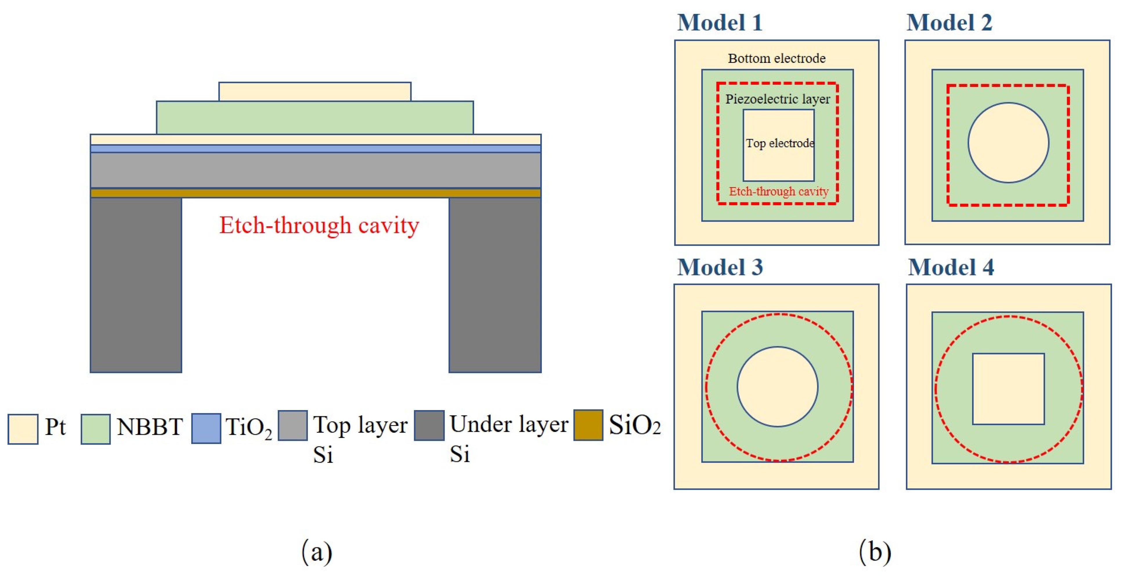
2.1. Design of PMUT Components for Structures

The common design process of PMUT mainly consists of the following steps: first, the material for each layer of the PMUT needs to be determined; second, the dimension of the PMUT is estimated based on material performance and desired operating frequency; finally, the optimized PMUT can be obtained by modifying the geometric structure and parameters.
The cross-section diagram of the PMUT structure based upon the NBBT single-crystal thin film is displayed in Figure 1a. The suspended membrane of the PMUT is made up of the top Pt electrode, the NBBT thin film, and the bottom Pt electrode combined on the top silicon wafer. The TiO2 layer acts as an adhesive between the Pt electrode and SiO2, and the SiO2 and Si at the bottom serve as the insulating layer and mechanical support base, respectively. Structures of PMUT with varying shapes of top electrodes and bottom cavities based on NBBT are put forward. To adjust and optimize the different structures of the model to obtain a PMUT structure with better performance, a PMUT structure with different top electrode and bottom cavity shapes based on NBBT is proposed. Figure 1b displays a top view. The piezoelectric layer in the four models is square-shaped. When combining the top electrode, either a square or round shape is chosen depending on the shape of the bottom cavity; the top electrode has the same area as the bottom cavity in the four models. Even though the circle has the same area as a square, the feature length is much greater.
The most effective and intuitive way to optimize and analyze a PMUT is by using a three-dimensional finite element model [26]. In this paper, four three-dimensional finite element models of PMUTs based on NBBT single-crystal thin film were built by utilizing COMSOL Multiphysics. The size of the PMUT is a crucial factor in determining the operating frequency. In order to achieve high-resolution ultrasonic imaging, the size of the PMUT needs to be lessened to tens of microns [27]. For a PMUT with NBBT thin films with a thicknesses of 1 μm and resonant frequencies of about 25 MHz, their element dimension should be ~50 μm. PMUT structural parameters are displayed in Table 2. The parameters of the polarized NBBT single-crystal material used in the finite element model [001] are shown in Table 3 [25]. In addition to NBBT, the material parameters needed for the PMUT model can be found in the COMSOL material depot. In modeling, constraints must be fixed on the bottom boundary of the base substrate. The electrostatic boundary condition is to set a voltage of 1 V at the top electrode and the bottom electrode is connected with the ground. The maximum dimension when meshing the grid is one-fifth of the wavelength of the given material in this PMUT model. It is noteworthy that at least two entity element scans in the direction of thickness.

2.2. Mode Shape Selection

To study the PMUT’s properties, the resonance mode frequency must be determined first. In Figure 2, the initial four excitation resonant modes of PMUT devices based on NBBT are illustrated. Red means it has a larger displacement while blue means it has a smaller displacement. Among them, the oscillations of (1, 1) and (2, 1) mode films in some regions are opposite and cancel each other, which attenuates the displacement at the center of the surface of the thin film. It cannot be applied in practice because it is difficult to excite in a medium environment. Therefore, we center on the acoustic performance of the first-class resonance mode (0, 1) as it has a higher energy concentration in the medium compared to the (0, 2) mode [28,29].

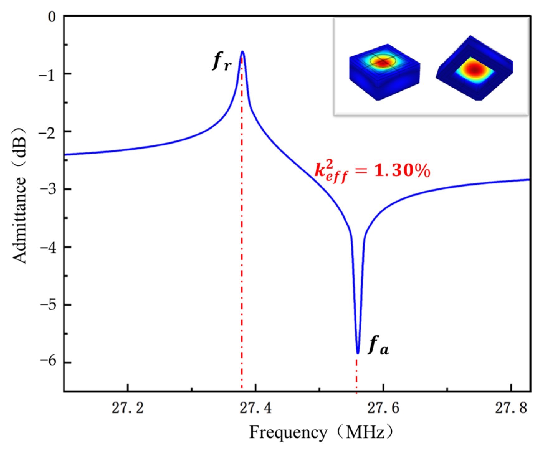
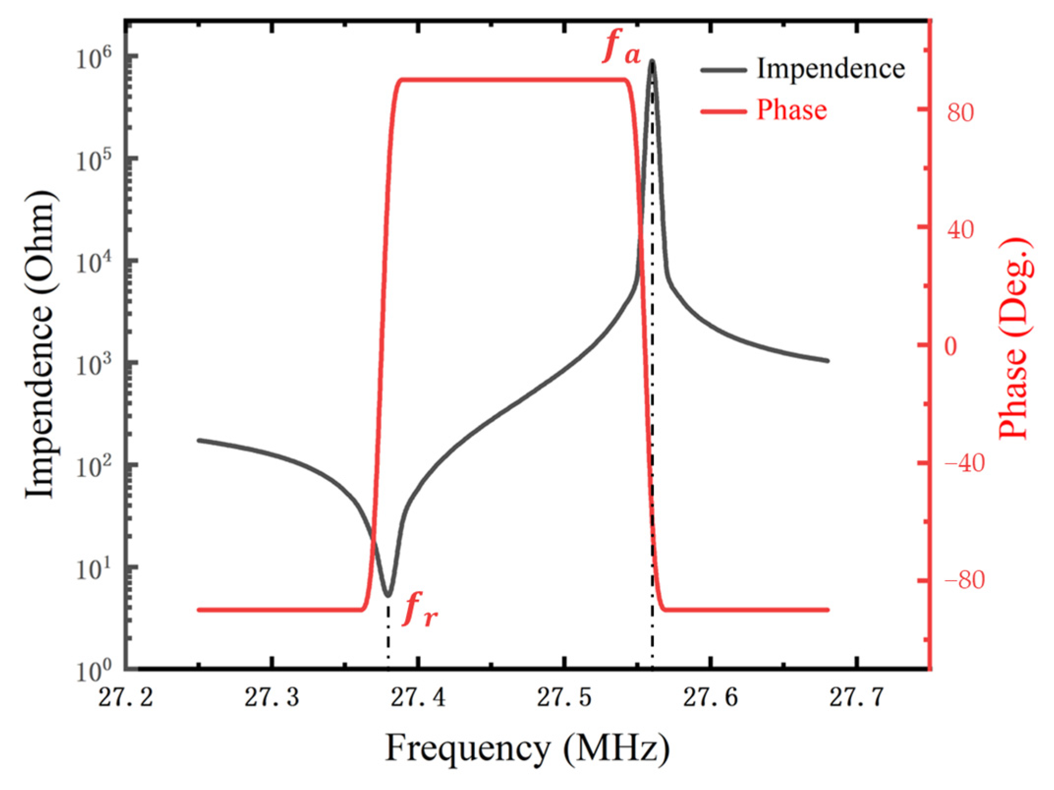
2.3. PMUT Property Evaluation

The mode shape of the PMUT was analyzed via COMSOL’s built-in eigenfrequency module, and the admittance of mode (0, 1) was calculated through the frequency domain analysis module. The resonant frequency   f r   and anti-resonant frequency f a   were determined. In order to disregard the geometric shape and excitation mode of a PMUT, the effective electromechanical coupling factor k e f f 2   can be defined as follows [30]:
k e f f 2 = 1 ( f r / f a ) 2
PMUTs are widely used in many fields because of their outstanding advantages. No matter the application, improving the transceiver performance of PMUTs is a common goal. Since a PMUT needs to switch between the transmitting state and the receiving state, it is necessary to improve not only the sensitivity of the transducer’s transmission but also the receiving sensitivity of the transducer. However, a PMUT used in medical imaging needs to ensure the transceiver performance of the transducer at high frequencies. Therefore, through steady-state analysis, the static emission sensitivity d s is taken as the measurement of the transmission performance and function of the PMUT, and the static reception sensitivity s r is taken as the criterion to measure the reception function and performance of the PMUT.
In the study of static transmitting sensitivity, an electric field of 10 V/μm should be utilized across the top electrode and the bottom electrode. In the study of static reception sensitivity, 100 kPa pressure should be applied on the surface of the thin film as the boundary load of the PMUT. Therefore, the voltage and displacement can be obtained on the central surface of the film. To determine the static emission sensitivity, one can calculate the displacement ratio of the voltage at the center of the thin film surface. Similarly, to calculate the static reception sensitivity, one can use the voltage ratio to stress the membrane surface [31].
Time-domain analysis was used to research the PMUT’s transmission and reception in water. While the top electrodes of the PMUT are charged, as well as the bottom electrodes, the reverse piezoelectric effect causes transverse pressure in the piezoelectric layer. The resulting pressure creates a bending moment that drives the membrane to deflect out of the plane, resulting in the emission of a sound pressure wave. Similarly, the incident pressure causes the membrane to deform owing to the forward piezoelectric effect. The PMUT emits ultrasonic waves into the medium and can also receive reflected echoes in the medium [32,33].
When a pulse is utilized to the top electrode, the pulse will be transmitted to a solid reflector, a portion of which will be reflected and received by the PMUT. The relative pulse sensitivity level M showing and expressing the dynamic sensitivity performance of the PMUT, is defined as the ratio of the first pulse-echo voltage’s maximum value U m a x and the reflector’s highest excitation voltage U 0   corresponding to the PMUT. Its mathematical formula is
M = 20 l g ( U m a x / U 0 ) ,
The spectrum’s amplitude is 50% of the frequency’s maximum value (−6 dB) and the expression for the center frequency is as follows:
f c = ( f h + f l ) / 2 ,
The −6 dB bandwidth is calculated as [34]
B W = f h f l f c × 100 %
where the amplitude of the echo decreases by 6 dB, the high frequency is f h and the low frequency is f l in the pulse-echo frequency spectrum when the amplitude of the echo decreases by 6 dB.

3. Results and Discussion

3.1. Static Analysis

3.1.1. General Features of PMUTs

With the same area, the top electrode has a difference in geometry from the bottom cavity and also a difference in the feature length, which has a great influence on the components utilized in the equivalent circuit, limiting the performance and function of PMUT devices. The study examined the effect of four characteristic lengths (side length or diameter) on the configurations of the top electrode and bottom cavity. The model was adjusted and optimized to obtain a PMUT structure with better performance. Table 4 shows four different PMUT configurations and their performance characteristics according to NBBT. The resonant frequency of all models reached more than 27 MHz. It is noteworthy that the effective electromechanical coupling factor k e f f 2 of model 3 with the circular top electrode and the circular bottom cavity was 1.3%, which was significantly improved compared with other models.   k e f f 2   is closely related to the electromechanical bandwidth, increasing the bandwidth, which is conducive to improving the ultrasonic transducer. Therefore, model 3 was taken as the main research object of further study, whose resonant frequency is 27.38 MHz, static transmitting sensitivity is 365.7 pm/V, and static receiving sensitivity is 0.0318 mV/kPa. The PMUT admittance of model 3 based on NBBT is shown in Figure 3. The impedance and phase of the PMUT based on NBBT model 3 are shown in Figure 4. The PMUT admittance of model 3 based on NBBT is displayed in Figure 3. Since the resonant frequency of the PMUT is a vital factor that determines the penetration resolution and depth, the obtained resonant frequency of 27 MHz for the proposed structure could benefit the requirements of medical ultrasound imaging
The results for model 3 are as follows. In addition, the PMUT properties of different piezoelectric materials based on model 3 are shown in Table 5. The PMUT in accordance with NBBT thin film reached up to 1.30%, which is three times higher than the PMUT structure based upon the widely used AlN piezoelectric film, and its static emission sensitivity was also superior. In general, NBBT single-crystal films have larger sensitivity and electromechanical coupling performance in terms of piezoelectric micromechanical ultrasonic transducers and can be a proper substitute for PMUT lead-free piezoelectric materials.

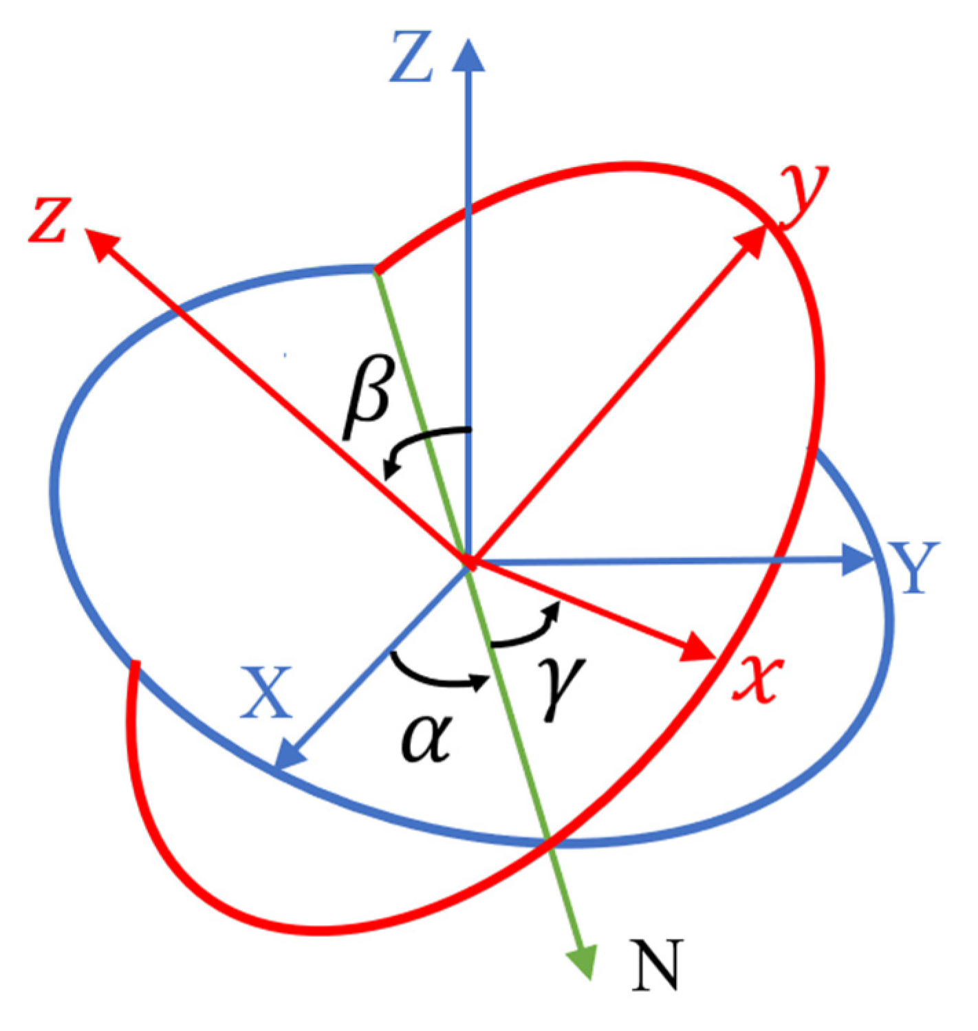
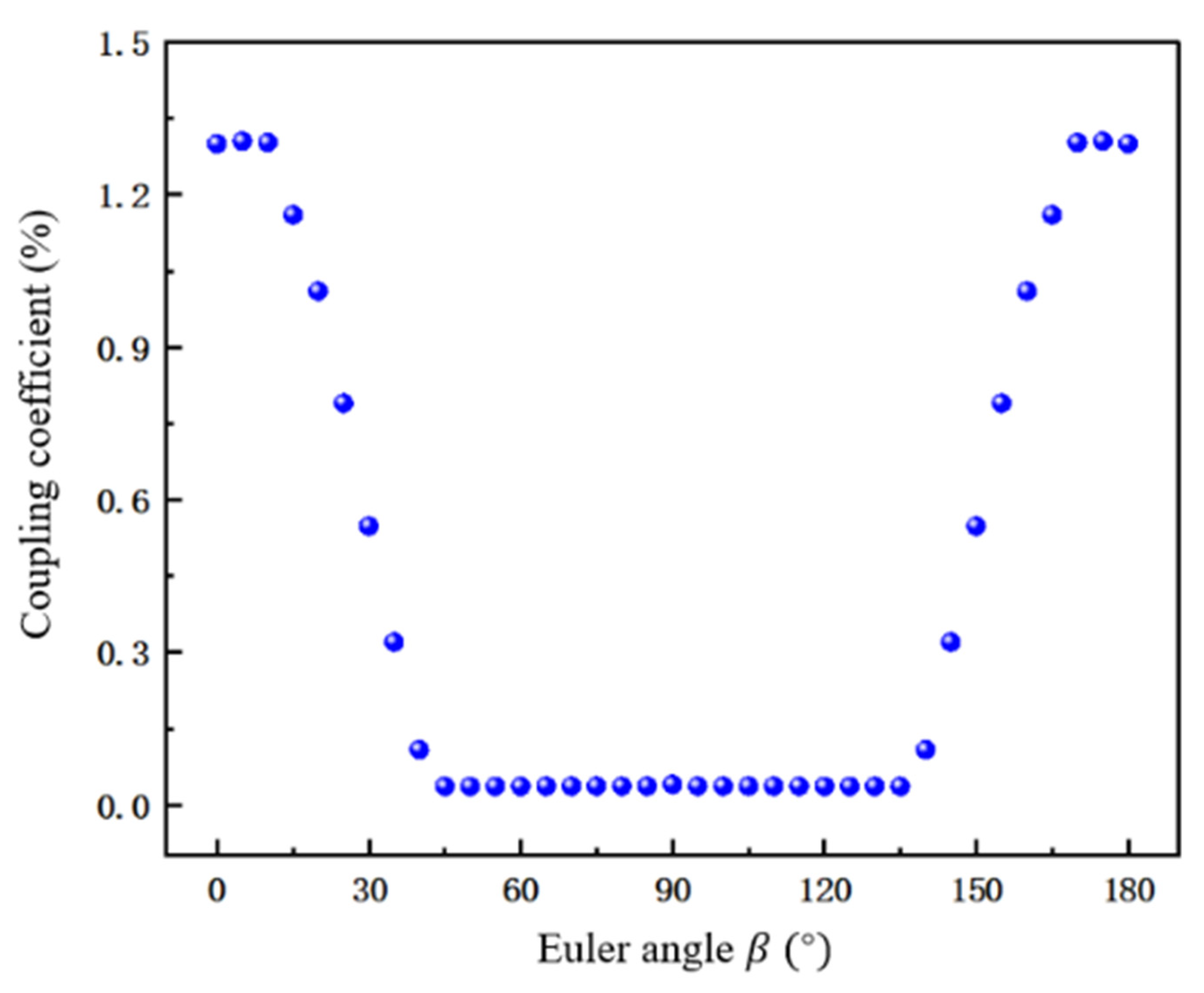
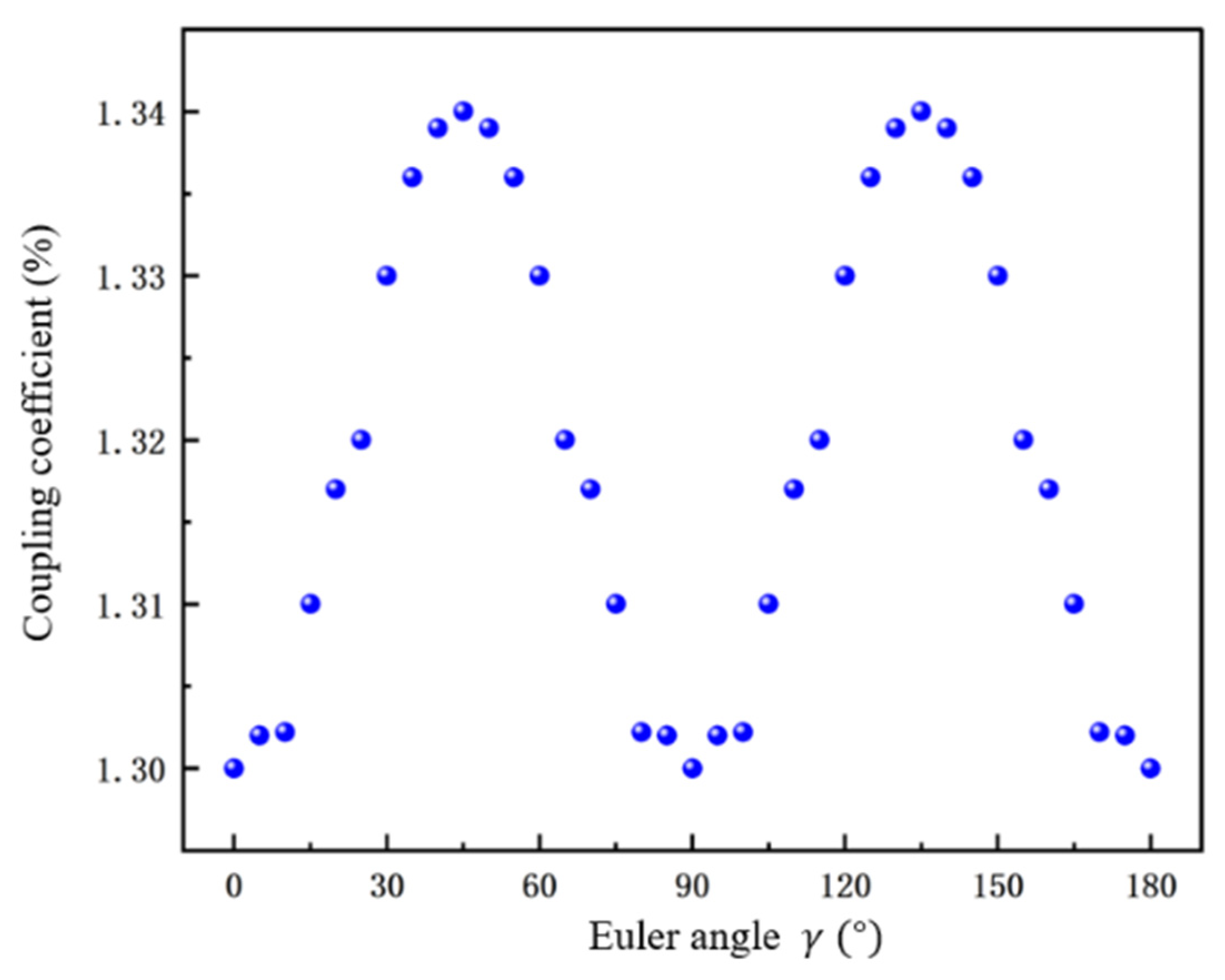
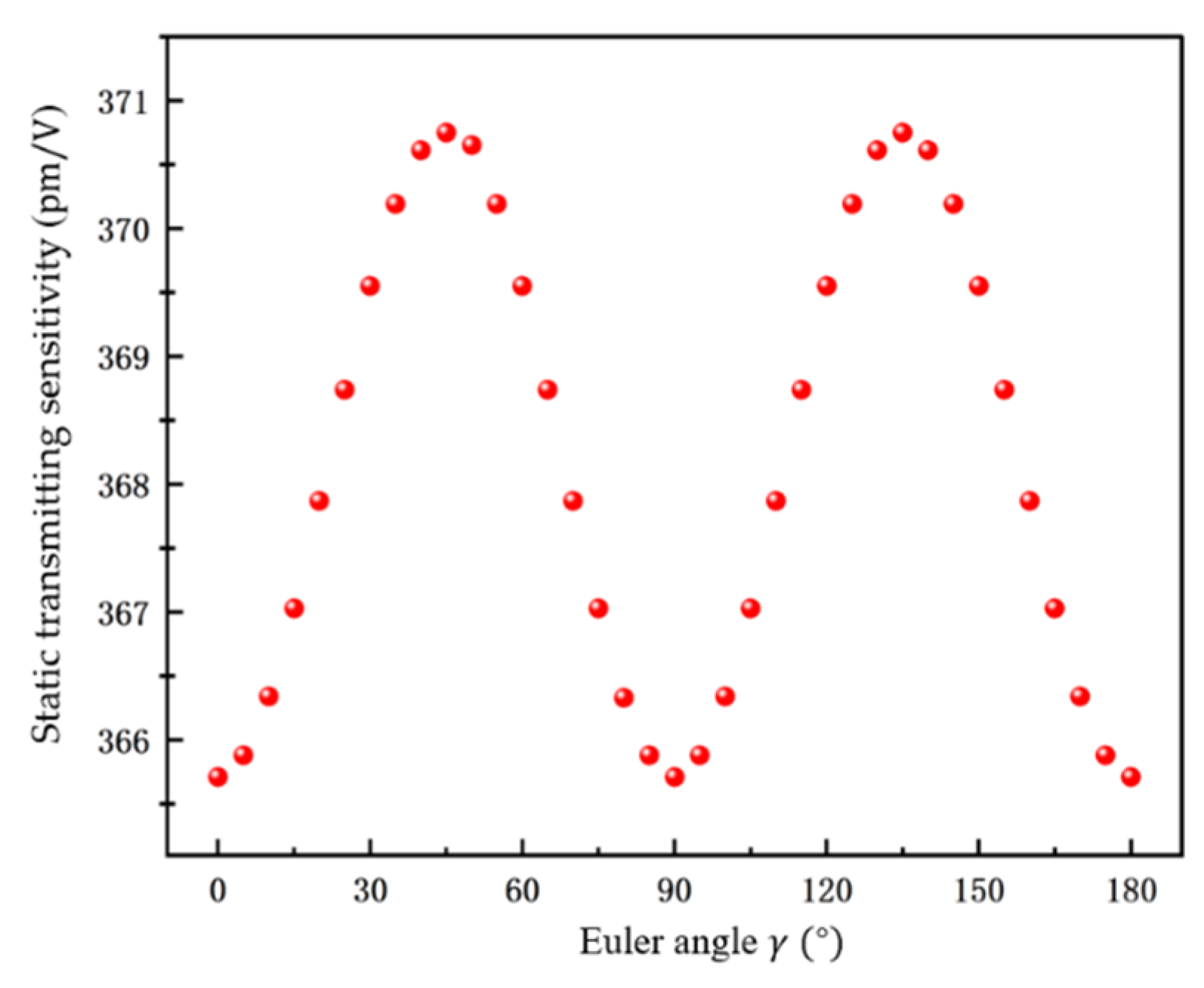
3.1.2. Influence of Euler Angle on the Performance of PMUT

To optimize the PMUT performance for NBBT single-crystal thin film, the Euler Angle rotation method was used to analyze the influence rule of different Euler Angles on the performance of the transducer. In COMSOL Multiphysics software, the rotating coordinate system shown in Figure 5 is adopted, and the Euler Angle is represented by ( α , β , γ ) [35]. The influence of Euler Angle rotation within a range on electromechanical coupling performance and static sensitivity of PMUT was studied.
First of all, the influence of the rotation of β from 0° to 180° on the mechanical and electrical coupling properties of the PMUT based upon NBBT single-crystal thin film was studied. In the simulation process, the other geometric dimension parameters were kept unchanged, except the Euler Angle β . Figure 6 plots the change curve of k e f f 2 with the change of Euler Angle β , which is obtained from the PMUT based on the polarization of the NBBT single-crystal film in the [001] direction after the Euler Angle rotation. As can be seen from the figure, the corresponding k e f f 2 highly depends on β . When β rotated from about 0° to about 45 degrees, k e f f 2   first linearly decreased and approached 0 when β was 45° .   When β rotated from about 45° to about 135° degrees, k e f f 2 was close to a stationary state. When β further rotated from about 135° to about 180°degrees, k e f f 2 linearly rose. As can be seen from the figure, β was symmetrical at 90°and when β was 0°, k e f f 2 reached its maximum at 0°.

3.1.3. Influence of Different Euler Angles on the Performance of PMUT

Keeping β at 0°, the influence of the Euler Angle on the performance of the PMUT was studied. Figure 7 shows the change of k e f f 2 from 0° to 180° after the Euler Angle rotation of the PMUT based on the direction of the [001] polarized NBBT single-crystal film. It can be seen from the figure that when γ rotated from 0° to 45°, k e f f 2 rose linearly, and when γ rotated from 45° to 90°, k e f f 2 fell linearly. The curve was symmetric about γ = 90°, that is, when γ was 45° and 135°, k e f f 2 obtained a maximum value of (1.34). The   k e f f 2 obtained after rotation was 10% higher than that of the PMUT structure when the electrode and bottom cavity were both square in shape.
Figure 8 shows the change in static transmitting sensitivity d s from 0° to 180° with the change of Euler Angle γ . The image is symmetrical about γ = 90°, and a maximum value of 370.75 pm/V was obtained when γ was 45° and 135°. Figure 9 shows the change in static receiving sensitivity s r from 0° to 180° with the change of γ . The image is symmetrical about γ = 90°, and the maximum value 0.032 mV/kPa was obtained when y was 45° and 135°, that is, when the optimized tangent was β = 0° and γ = 45 ± 5°, k e f f 2 , d s and s r of the PMUT along the [001] polarized NBBT single-crystal film reached a maximum value.

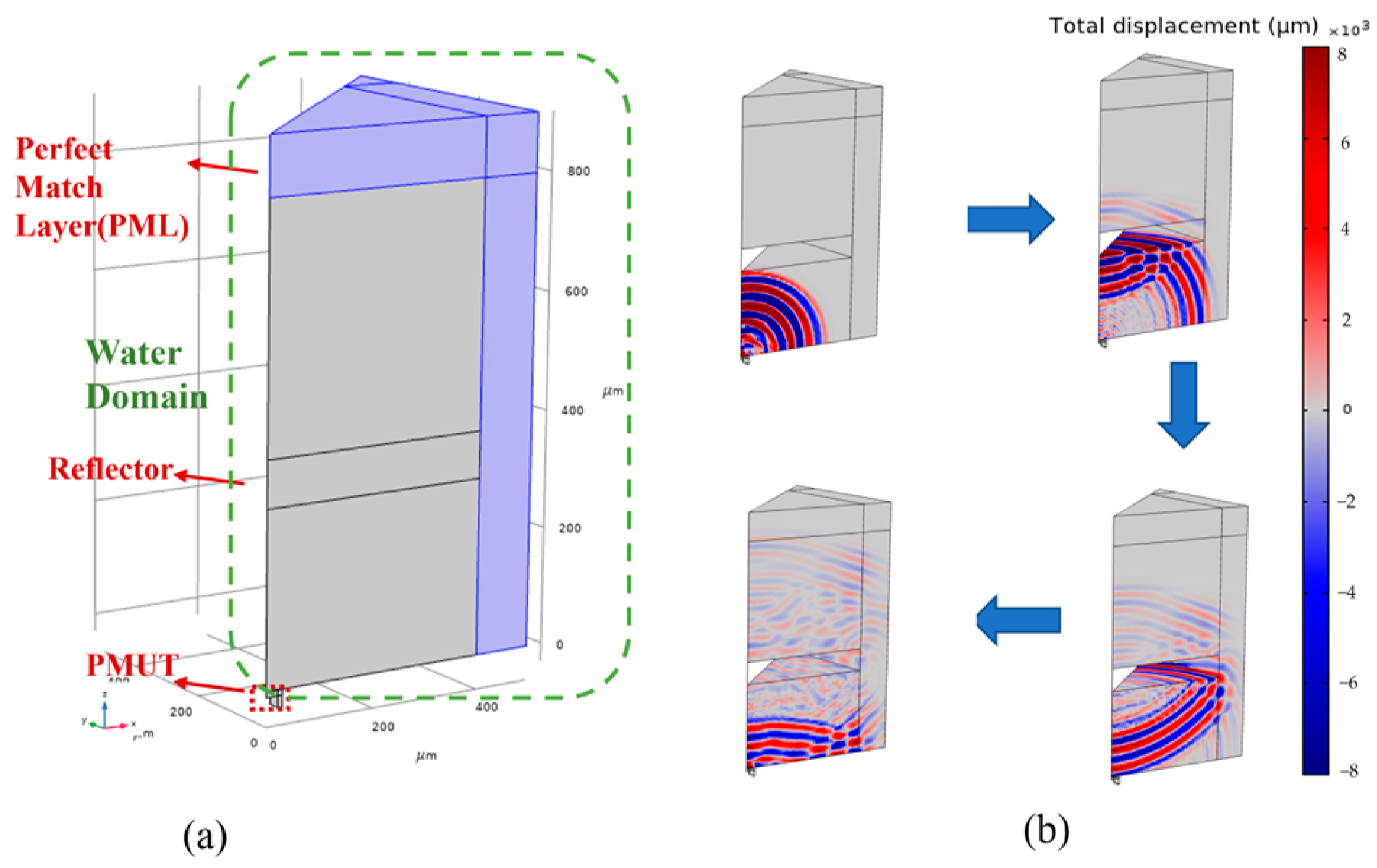
3.2. Analyzing Dynamism

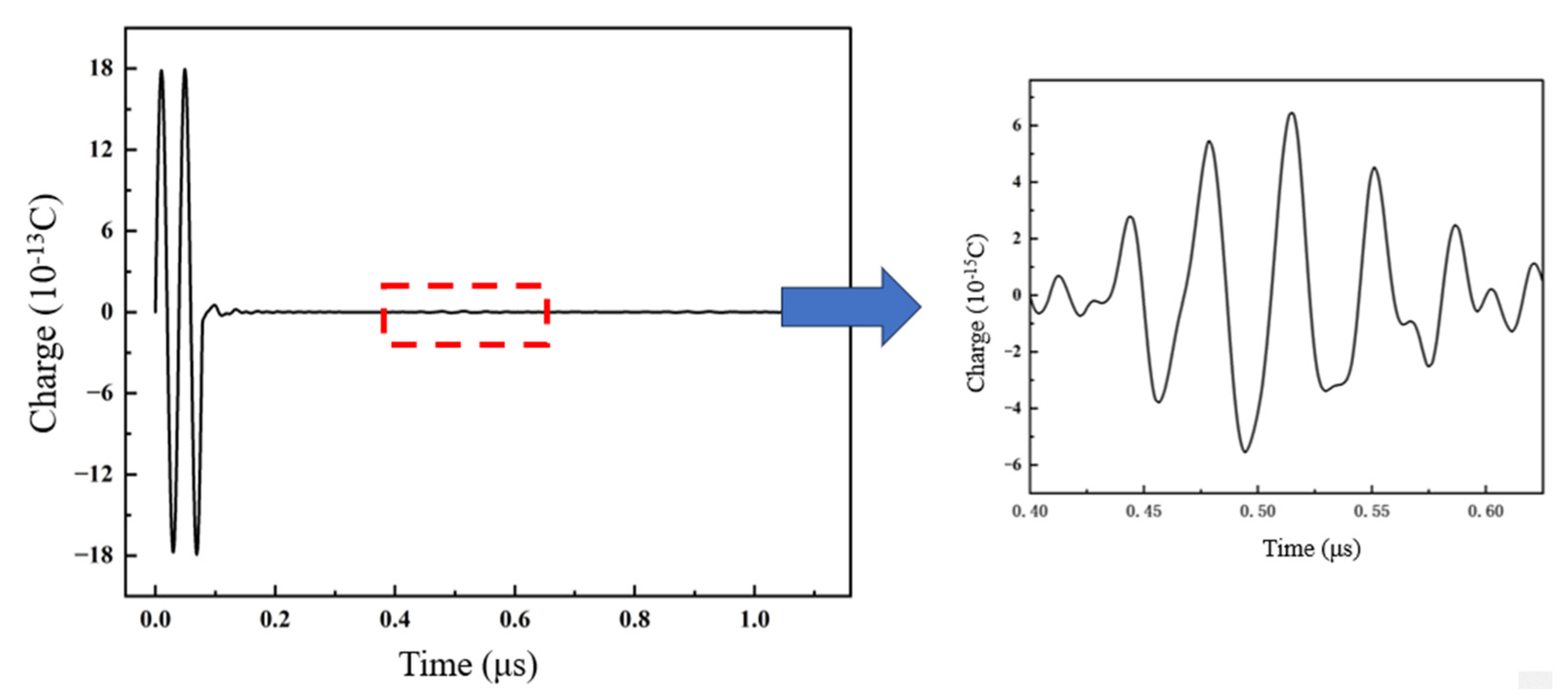
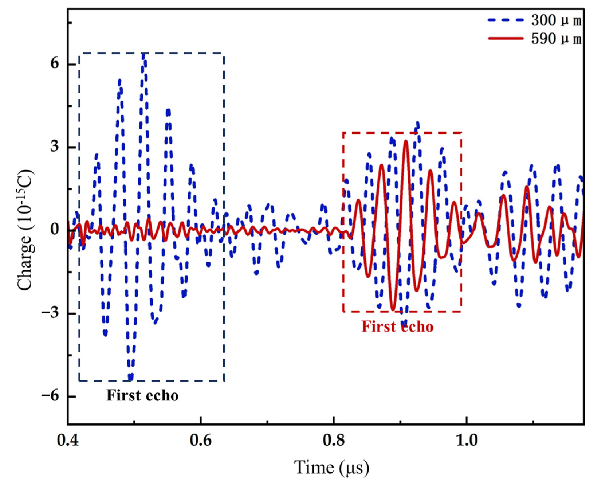
3.2.1. Pulse-Echo Sensitivity of PMUT

Through time-domain analysis, the dynamic transmission and reception characteristics of the PMUT in accordance with NBBT single-crystal thin film in water were researched and studied. Considering the complicated structure and grid cells that require significant computing resources, the computational efficiency of a PMUT is low, so the waters and the perfectly matched layer (PML) were simplified to a one-eighth model. Figure 10a displays a one-eighth-scale water model of a PMUT with a circular top electrode and bottom cavity. The solid reflector is placed on the central axis of the PMUT. The PMUT and solid reflectors are a part of the solid mechanic module, piezoelectric materials are a part of the electrostatic module, and water and PML layers are a part of the pressure acoustic module. Prior to the mode conversion [36], two cycles of sinusoidal pulses are applied to the top electrode at the PMUT resonant frequency. In addition, the simulation includes the sound field in water. When sound waves hit the steel plate, some are reflected, picked up by the PMUT, and turned back. The sound pressure change in water is displayed in Figure 10b during this process. It can be concluded that PMUT produces uniform sound pressure in water ( v w a t e r = 1500 m/s) at the resonant frequency, where the wavelength λ is about 59 μm.
The PMUT charge response to the reflector at 300 µm in water is plotted in Figure 11. The image on the right is a magnified image of the echo. The first pulse-echo voltage U m a x   = 6.4 × 10⁻¹² and the peak-excitation voltage U 0   = 1.8 × 10⁻¹⁵. According to Formula (2), the PMUT has a relative pulse-echo sensitivity of approximately −49 dB. Figure 12 compares the received signal from the reflector at 300 µm to 590 µm. As shown in the figure, the first echo amplitude of a PMUT with a 300 µm reflector was greater than that shown in a PMUT with a 590 µm reflective film, and the relative pulse-echo sensitivity was approximately −55 dB at 590 µm. Therefore, when the reflector is utilized and placed further away, the first echo amplitude will appear later as the distance decreases, and the sensitivity of the pulse-echo will decrease in proportion to its relative value.

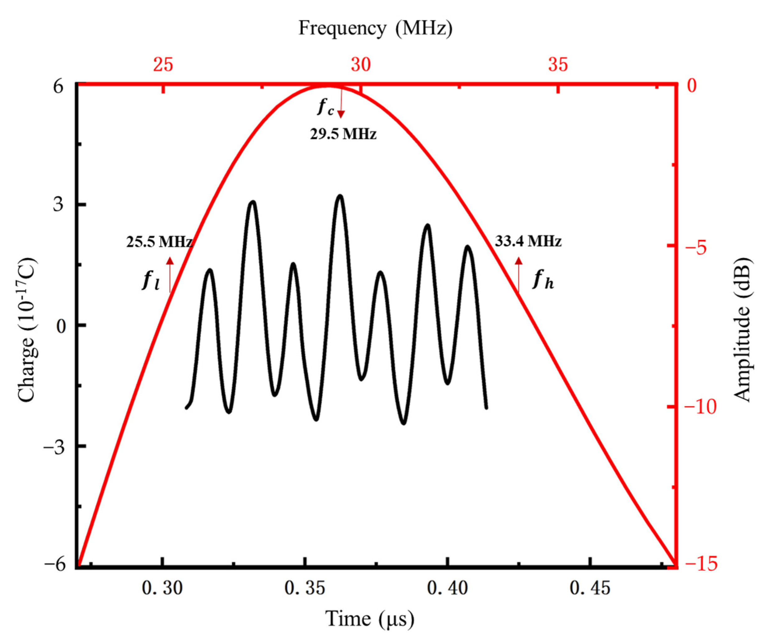
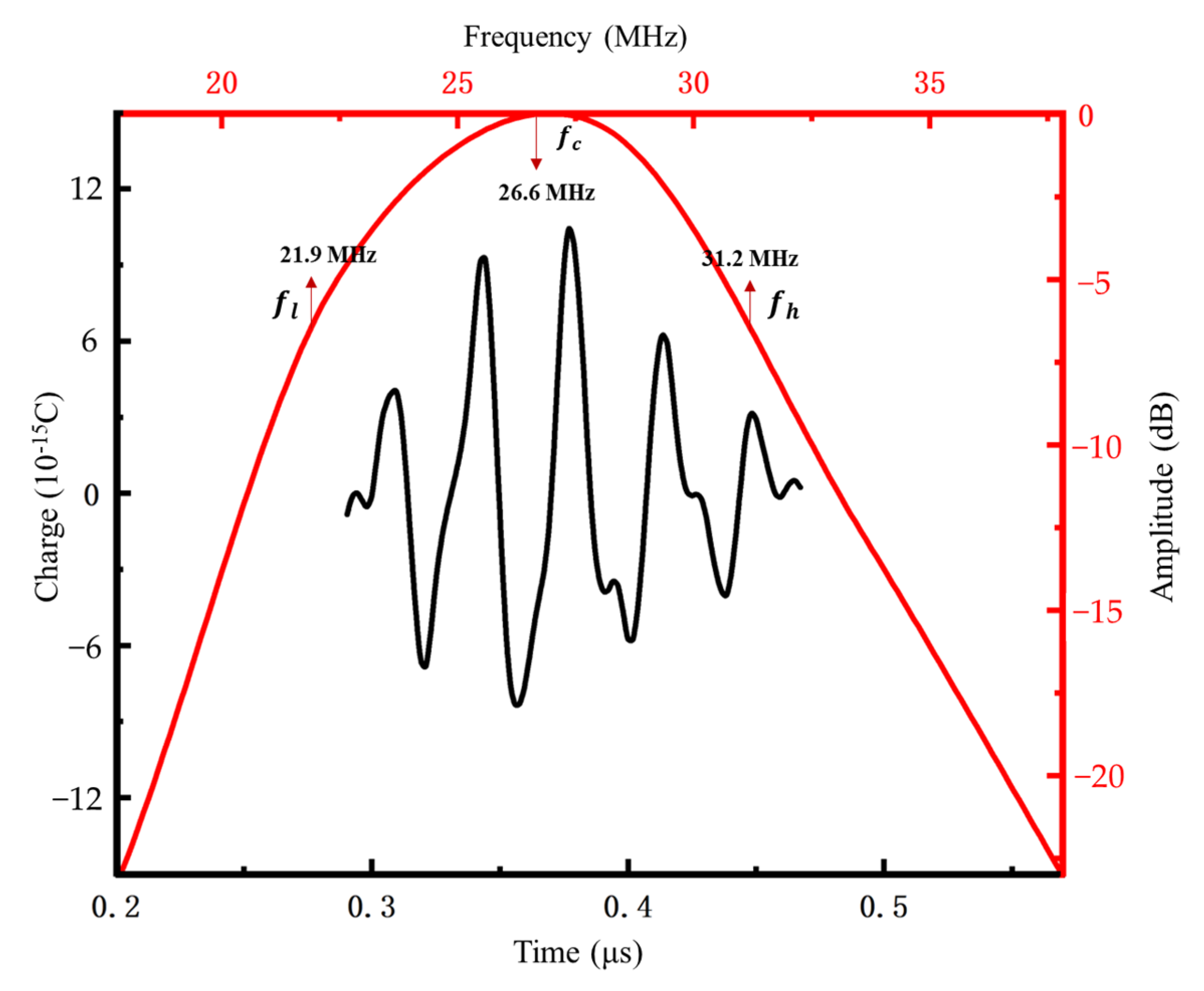
3.2.2. Frequencies and Bandwidths of PMUTs

The pulse-echo response is used to transform the frequency–amplitude spectra of pulse echoes through the Fast Fourier Transform (FFT). Figure 13 and Figure 14 correspond to the pulse echo (black curve) and frequency response (red curve) of the PMUT based on NBBT film and the PMUT based on AlN film under a 200 µm underwater reflector, respectively. As displayed in the figure, when the center frequency of the PMUT based on NBBT film was 26.4 MHz, the high and low frequencies corresponding to −6 dB were 21.9 MHz and 30.9 MHz, respectively, and the bandwidth was about 34.1%. When the center frequency of the PMUT based on AlN film was 29.5 MHz, the high and low frequencies corresponding to −6 dB were 25.5 MHz and 33.4 MHz, respectively, and the bandwidth was about 26.8%. Table 6 compares the pulse-echo sensitivity levels, center frequencies, and bandwidths to determine their relative differences. It can be seen from the figure that the AlN bandwidth and dynamic and static sensitivity are significantly lower than that of the PMUT based on NBBT piezoelectric film.
Figure 15 shows the pulse echo (black curve) and frequency response (red curve) of the NBBT-based PMUT under the underwater 200 µm reflector after Euler Angle rotation. The center frequency was 26.6 MHz, as shown in Figure 15. The lower −6 dB and upper −6 dB frequencies were 21.9 and 31.2 MHz, respectively, resulting in a bandwidth of about 35%. Table 7 makes a comparison among the relative pulse-echo sensitivity levels, center frequencies, and bandwidths of the NBBT-based PMUT models before and after Euler Angle rotation. After Euler Angle rotation, k e f f 2 , bandwidth and static sensitivity of the pulse echo are improved. In other words, the simulation conclusion shows that the sensitivity and bandwidth of the PMUT structure according to the NBBT single-crystal membrane can be improved by the Euler Angle rotation method, which supplies a theoretical basis for the development of a high-performance, high-resolution, and high-frequency ultrasonic transducer.

4. Conclusions

In this work, a PMUT device based on [001] polarized lead-free and high-performance NBBT piezoelectric single-crystal films was proposed and analyzed. The PMUT was modeled and optimized by the finite-element method. The results showed that the resonant frequency of a PMUT based on NBBT with a round top electrode and a round bottom cavity can reach 27.38 MHz, and its k e f f 2 of the PMUT was as high as 1.3%, which is three times higher than that of a PMUT in accordance with widely used AlN films; the static and dynamic sensitivity was also more advantageous than that of an AlN-based PMUT. After the Euler Angle rotation of NBBT, the bandwidth of the PMUT model based on NBBT was improved. Meanwhile, the static sensitivity after rotation was also improved to 370.75 pm/V and 0.032 mV/kPa. The investigation results showed that the proposed PMUT device based on NBBT lead-free piezoelectric single-crystal films has good application prospects in high-resolution and high-frequency medical ultrasound imaging. It is also safe for the human body and the environment. Furthermore, the proposed model can also provide the possibility for further optimization and improvement of PMUTs with high performance.

Author Contributions

Writing—original draft preparation, software, Y.L.; software, review, and editing, Q.Z.; software, M.C.; formal analysis, X.L.; resources, J.Y.; visualization, F.W.; investigation, Y.T.; investigation, B.M.; investigation, J.L.; supervision, conceptualization, X.Z. All authors have read and agreed to the published version of the manuscript.

Funding

This work was supported by the National Natural Science Foundation of China (Grant No. 52172005), the Research and Development Program in Significant Area of Guangzhou City (Grant No. 202206070001), the Science and Technology Commission of Shanghai Municipality (Grant No. 19070502800) and the National Natural Science Youth Foundation of China (Grant No. 11904233).

Data Availability Statement

The data presented in this study are available on request from the corresponding author.

Conflicts of Interest

The authors declare no conflict of interest.

References

  1. Lamberti, N.; Caliano, G.; Iula, A.; Savoia, A.S. A high frequency CMUT probe for ultrasound imaging of fingerprints. Sens. Actuators A Phys. 2011, 172, 561–569. [Google Scholar]
  2. Li, S.; Tian, J.; Jiang, X. A micromachined Pb (Mg1/3Nb2/3) O3-PbTiO3 single crystal composite circular array for intravascular ultrasound imaging. J. Eng. Sci. Med. Diagn. Ther. 2019, 2, 2. [Google Scholar]
  3. Kim, J.; Li, S.; Kasoji, S.; Dayton, P.A.; Jiang, X. Phantom evaluation of stacked-type dual-frequency 1–3 composite transducers: A feasibility study on intracavitary acoustic angiography. Ultrasonics 2015, 63, 7–15. [Google Scholar]
  4. Lockwood, G.R.; Turnball, D.H.; Christopher, D.A.; Foster, F.S. Beyond 30 MHz applications of high-frequency ultrasound imaging. IEEE Eng. Med. Biol. Mag. 1996, 15, 60–71. [Google Scholar]
  5. Takenaka, T.; Nagata, H. Current status and prospects of lead-free piezoelectric ceramics. J. Eur. Ceram. Soc. 2005, 25, 2693–2700. [Google Scholar]
  6. Fei, C.; Yang, Y.; Guo, F.; Lin, P.; Chen, Q.; Zhou, Q.; Sun, L. PMN-PT single crystal ultrasonic transducer with half-concave geometric design for IVUS imaging. IEEE Trans. Biomed. Eng. 2017, 65, 2087–2092. [Google Scholar]
  7. Lee, W.; Roh, Y. Ultrasonic transducers for medical diagnostic imaging. Biomed. Eng. Lett. 2017, 7, 91–97. [Google Scholar] [PubMed]
  8. Muralt, P.; Ledermann, N.; Paborowski, J.; Barzegar, A.; Gentil, S.; Belgacem, B.; Setter, N. Piezoelectric micromachined ultrasonic transducers based on PZT thin films. IEEE Trans. Ultrason. Ferroelectr. Freq. Control 2005, 52, 2276–2288. [Google Scholar]
  9. Sano, K.H.; Karasawa, R.; Yanagitani, T. ScAlN thick-film ultrasonic transducer in 40–80 MHz. IEEE Trans. Ultrason. Ferroelectr. Freq. Control 2018, 65, 2097–2102. [Google Scholar]
  10. Dausch, D.E.; Castellucci, J.B.; Chou, D.R.; Von Ramm, O.T. Theory and operation of 2-D array piezoelectric micromachined ultrasound transducers. IEEE Trans. Ultrason. Ferroelectr. Freq. Control 2008, 55, 2484–2492. [Google Scholar] [CrossRef]
  11. Tressler, J.F.; Alkoy, S.; Newnham, R.E. Piezoelectric sensors and sensor materials. J. Electroceramics 1998, 2, 257–272. [Google Scholar] [CrossRef]
  12. Akhbari, S.; Sammoura, F.; Shelton, S.; Yang, C.; Horsley, D.; Lin, L. Highly responsive curved aluminum nitride pMUT. In Proceedings of the 2014 IEEE 27th International Conference on Micro Electro Mechanical Systems (MEMS), San Francisco, CA, USA, 13 March 2014. [Google Scholar]
  13. Jung, J.; Annapureddy, V.; Hwang, G.T.; Song, Y.; Lee, W.; Kang, W.; Choi, H. 31-mode piezoelectric micromachined ultrasonic transducer with PZT thick film by granule spraying in vacuum process. Appl. Phys. Lett. 2017, 110, 212903. [Google Scholar] [CrossRef]
  14. Przybyla, R.; Izyumin, I.; Kline, M.; Boser, B.; Shelton, S.; Guedes, A.; Horsley, D. An ultrasonic rangefinder based on an AlN piezoelectric micromachined ultrasound transducer. In Proceedings of the Sensors, San Francisco, CA, USA, 26–30 January 2014. [Google Scholar]
  15. Wang, X.X.; Tang, X.G.; Chan, H.L.W. Electromechanical and ferroelectric properties of (Bi1/2Na1/2) TiO3–(Bi1/2 K1/2) TiO3–BaTiO3 lead-free piezoelectric ceramics. Appl. Phys. Lett. 2004, 85, 91–93. [Google Scholar] [CrossRef]
  16. Chen, C.; Zhao, X.; Wang, Y.; Zhang, H.; Deng, H.; Li, X.; Luo, H. Giant strain and electric-field-induced phase transition in lead-free (Na0.5Bi0.5) TiO3-BaTiO3-(K0.5Na0.5) NbO3 single crystal. Appl. Phys. Lett. 2016, 108, 022903. [Google Scholar] [CrossRef]
  17. Saito, Y.; Takao, H.; Tani, T.; Nonoyama, T.; Takatori, K.; Homma, T.; Nakamura, M. Lead-free piezoceramics. Nature 2004, 432, 84–87. [Google Scholar] [CrossRef]
  18. Lin, D.; Kwok, K.W.; Lam, K.H.; Chan, H.L.W. Phase structure and electrical properties of K0.5Na0.5 (Nb0.94Sb0.06) O3-LiTaO3 lead-free piezoelectric ceramics. J. Phys. D Appl. Phys. 2008, 41, 052002. [Google Scholar] [CrossRef]
  19. Chiang, Y.M.; Farrey, G.W.; Soukhojak, A.N. Lead-free high-strain single-crystal piezoelectrics in the alkaline–bismuth–titanate perovskite family. Appl. Phys. Lett. 1998, 73, 3683–3685. [Google Scholar] [CrossRef]
  20. Lu, Y.; Reusch, M.; Kurz, N.; Ding, A.; Christoph, T.; Prescher, M.; Žukauskaitė, A. Elastic modulus and coefficient of thermal expansion of piezoelectric Al1−xScxN (up to x = 0.41) thin films. APL Mater. 2018, 6, 076105. [Google Scholar] [CrossRef]
  21. Jo, W.; Daniels, J.E.; Jones, J.L.; Tan, X.; Thomas, P.A.; Damjanovic, D.; Rödel, J. Evolving morphotropic phase boundary in lead-free (Bi1/2 Na1/2) TiO3–BaTiO3 piezoceramics. J. Appl. Phys. 2011, 109, 014110. [Google Scholar] [CrossRef]
  22. Takenaka, T.; Maruyama, K.I.M.K.I.; Sakata, K.S.K. (Bi1/2Na1/2) TiO3-BaTiO3 system for lead-free piezoelectric ceramics. Jpn. J. Appl. Phys. 1991, 30, 2236. [Google Scholar] [CrossRef]
  23. Chu, B.J.; Chen, D.R.; Li, G.R.; Yin, Q.R. Electrical properties of Na1/2Bi1/2TiO3–BaTiO3 ceramics. J. Eur. Ceram. Soc. 2002, 22, 2115–2121. [Google Scholar] [CrossRef]
  24. Caro, M.A.; Zhang, S.; Riekkinen, T.; Ylilammi, M.; Moram, M.A.; Lopez-Acevedo, O.; Laurila, T. Piezoelectric coefficients and spontaneous polarization of ScAlN. J. Phys. Condens. Matter 2015, 27, 245901. [Google Scholar] [CrossRef]
  25. Zheng, L.; Yi, X.; Zhang, S.; Jiang, W.; Yang, B.; Zhang, R.; Cao, W. Complete set of material constants of 0.95 (Na0.5Bi0.5) TiO3-0.05 BaTiO3 lead-free piezoelectric single crystal and the delineation of extrinsic contributions. Appl. Phys. Lett. 2013, 103, 122905. [Google Scholar] [CrossRef]
  26. Liu, W.; He, L.; Wang, X.; Zhou, J.; Xu, W.; Smagin, N.; Ren, J. 3D FEM analysis of high-frequency AlN-based PMUT arrays on cavity SOI. Sensors 2019, 19, 4450. [Google Scholar] [CrossRef]
  27. Jiang, X.; Lu, Y.; Tang, H.Y.; Tsai, J.M.; Ng, E.J.; Daneman, M.J.; Horsley, D.A. Monolithic ultrasound fingerprint sensor. Microsyst. Nanoeng. 2017, 3, 17059. [Google Scholar] [CrossRef] [PubMed]
  28. Chen, M.Z.; Zhang, Q.Z.; Zhao, X.Y.; Wang, F.F. Modeling and simulation of aluminium nitride-based piezoelectric micromachined ultrasonic transducer for ultrasound imaging. In Proceedings of the 2019 14th Symposium on Piezoelectrcity, Acoustic Waves and Device Applications (SPAWDA), Shijiazhuang, China, 1–4 November 2019. [Google Scholar]
  29. Wilm, M.; Reinhardt, A.; Laude, V.; Armati, R.; Daniau, W.; Ballandras, S. Three-dimensional modelling of micromachined-ultrasonic-transducer arrays operating in water. Ultrasonics 2005, 43, 457–465. [Google Scholar] [CrossRef] [PubMed]
  30. Meeker, T.R. Publication and proposed revision of ANSI/IEEE standard 176-1987. IEEE Trans. Ultrason. Ferroelectr. Freq. Control 1996, 43, 717–772. [Google Scholar]
  31. Guo, J.Q.; Liu, C.C.; Han, T.; Miao, J.M. Model of scandium doped aluminum nitride based PMUT with high transmitting performance. In Proceedings of the 2017 Symposium on Piezoelectricity, Acoustic Waves, and Device Applications (SPAWDA), Chengdu, China, 27–30 October 2017. [Google Scholar]
  32. Przybyla, R.J.; Shelton, S.E.; Guedes, A.; Izyumin, I.I.; Kline, M.H.; Horsley, D.A.; Boser, B.E. In-air rangefinding with an AlN piezoelectric micromachined ultrasound transducer. IEEE Sens. J. 2011, 11, 2690–2697. [Google Scholar] [CrossRef]
  33. Lu, Y.; Tang, H.Y.; Fung, S.; Boser, B.E.; Horsley, D.A. Pulse-echo ultrasound imaging using an AlN piezoelectric micromachined ultrasonic transducer array with transmit beam-forming. J. Microelectromech. Syst. 2015, 25, 179–187. [Google Scholar] [CrossRef]
  34. Chen, M.; Zhang, Q.; Zhao, X.; Wang, F.; Liu, H.; Li, B.; Luo, H. Design and analysis of piezoelectric micromachined ultrasonic transducer using high coupling PMN-PT single crystal thin film for ultrasound imaging. Smart Mater. Struct. 2021, 30, 055006. [Google Scholar] [CrossRef]
  35. Li, X.; Zhang, R.; Huang, N.; Lü, T.; Cao, W. Surface acoustic wave propagation in Y-and Z-cut 0.67 PbMgNbO3–0.33 PbTiO3 single crystals. J. Appl. Phys. 2009, 106, 054110. [Google Scholar] [CrossRef] [PubMed]
  36. Gijsenbergh, P.; Halbach, A.; Jeong, Y.; Torri, G.B.; Billen, M.; Demi, L.; Rochus, V. Characterization of polymer-based piezoelectric micromachined ultrasound transducers for short-range gesture recognition applications. J. Micromech. Microeng. 2019, 29, 074001. [Google Scholar] [CrossRef]
Figure 1. (a) Cross-sectional diagram of a piezoelectric micromachined ultrasonic transducer (PMUT) based on NBBT. (b) Layouts from a top-view perspective of NBBT-based PMUTs with four different configurations.
Crystals 13 01394 g001
Figure 2. First four typical vibrational modes of NBBT-based PMUTs employing model 3.
Crystals 13 01394 g002
Figure 3. The admittance of the NBBT-based PMUT for the circular electrode and circular cavity.
Crystals 13 01394 g003
Figure 4. The impendence and phase diagram of the NBBT-based PMUT for the circular electrode and circular cavity.
Crystals 13 01394 g004
Figure 5. Rotating coordinate system used in the FEM model.
Crystals 13 01394 g005
Figure 6. The curve of the coupling coefficient k e f f 2 with the Euler Angle   β .
Crystals 13 01394 g006
Figure 7. The curve of the coupling coefficient k e f f 2 with the Euler Angle   γ .
Crystals 13 01394 g007
Figure 8. The curve of the static transmitting sensitivity d s   . with the Euler Angle   γ .
Crystals 13 01394 g008
Figure 9. The curve of the static receiving sensitivity s r with the Euler Angle   γ .
Crystals 13 01394 g009
Figure 10. (a) One-eighth model of the PMUT element with an acoustic range and an acoustic PML. (b) Sound pressure varies at different times.
Crystals 13 01394 g010
Figure 11. Pulse echo with a reflector located at 300 µm.
Crystals 13 01394 g011
Figure 12. Charge responses with a reflector at 300 µm (blue line) and 590 µm (red line).
Crystals 13 01394 g012
Figure 13. Pulse echo (black curve) and frequency response (red curve) before Euler angular rotation underwater with a reflector at 200 µm.
Crystals 13 01394 g013
Figure 14. Pulse echo (black curve) and the frequency response (red curve) after Euler angular rotation underwater with a reflector at 200 µm.
Crystals 13 01394 g014
Figure 15. Pulse echo (black curve) and frequency response (red curve) of the NBBT-based PMUT under the underwater 200 µm reflector after Euler Angle rotation.
Crystals 13 01394 g015
Table 1. Critical material characteristics of aluminum nitride (AlN) and [001] poled 0.95(Na0.5Bi0.5)TiO3-0.05BaTiO3(NBBT).
Material
Coefficient
AlN [24][001] Poled NBBT [25]
e 31 , f   C m 1   1.0 1.7
  d 33   ( p C N 1 ) ~ 5.5 ~ 360
  ε 33 S ~ 10 ~ 489
k 33 ~ 39 % ~ 72 %
e 31 , f : piezoelectric constant; ε 33 S : dielectric constant;   d 33 : piezoelectric constant; k 33 : electromechanical coupling coefficient.
Table 2. Structural parameters used for the simulation of the NBBT-based PMUT.
ParameterValue
Thickness of the top Pt200 nm
Thickness of the NBBT1 μm
Thickness of the bottom Pt200 nm
Thickness of TiO2 30 nm
Thickness of SiO2200 nm
Thickness of the top Si10 μm
Side length of the NBBT50 μm
Side length of the top Pt (models 1 and 4)30 μm
Radius of the top Pt (models 2 and 3)16.93 μm
Side length of the cavity (models 1 and 2)44.3 μm
Radius of the cavity (models 3 and 4)25 μm
Table 3. Measurement and derivation constants of the NBBT95/5 single-crystal poled along [001] (Density: ρ = 5777 kg/m3) [25].
Elastic   stiffness   constants:   c i j E   a n d   c i j D   ( 10 10   N / m 2 )
      c 11 E *       c 12 E c 13 E c 33 E * c 44 E * c 66 E * c 11 D c 12 D c 13 D c 33 D * c 44 D * c 66 D
15.99.57.58.17.57.816.09.67.111.49.47.8
Elastic compliance constants:   s i j E   a n d   s i j D   ( 10 12   m 2 / N )
      s 11 E *       s 12 E s 13 E s 33 E * s 44 E * s 66 E * s 11 D s 12 D s 13 D s 33 D * s 44 D s 66 D
12.2−3.4−8.227.713.412.910.8 −4.8−3.713.310.712.9
Piezoelectric coefficients:   e i λ   ( C / m 2 ) ,   d i λ   ( 10 12   C / N ) ,   g i λ   ( 10 3   V m / N ) ,   a n d   h i λ   ( 10 8   V / m )
      e 15 e 31 e 33 d 15 * d 31 * d 33 * g 15 g 31 g 33 h 15 h 31 h 33
12.1−1.712.0162−11336016.7−12.539.815.6−3.927.7
Dielectric constants:   ε i j ε 0   a n d   β i j   ( 10 4 / ε 0 ) Electromechanical coupling factors
      ε 11 T *       ε 33 T * ε 11 S * s 33 E * β 11 T β 33 T β 11 S β 33 S k 15 * k 31 * k 33 * k t *
109910218774899.19.811.420.40.4490.3410.7200.540
* Directly measured properties.
Table 4. Key performance characteristics of the NBBT-based PMUT with four different configurations.
Configurations
Properties
Model 1
Square Top Electrode
Model 2
Circular Top Electrode
Model 3
Circular Top Electrode
Model 4
Square Top Electrode
Resonant frequency f (MHz)28.4628.4127.3827.38
Effective electromechanical coupling k e f f 2 (%)1.221.191.301.26
Static transmitting sensitivity   d s   p m   V 1     314.1471.4365.7379.2
Static receiving sensitivity   s r   m V k P a 1         0.02820.03930.03180.0315
Square electrode cavityCircular electrode cavity
Table 5. PMUT performance comparison based on the circular electrode and cavity using different piezoelectric materials.
Piezoelectric Materials.
Properties for PMUT
NBBTAlN
Resonant frequency   f (MHz)27.3829.63
Effective Electromechanical
coupling k e f f 2 (%)
1.300.40
Static transmitting
sensitivity d s   p m / V
365.7127.09
Static receiving
Sensitivity   s r   m V / k P a
0.03180.271
Table 6. Bandwidths and center frequencies of the PMUT in accordance with the NBBT and the PMUT based on AlN with model 3 at 200 µm.
NBBTAlN
Relative pulse-echo sensitivity level (dB)−47−54
Lower/upper −6 dB (MHz)21.9/30.925.5/33.4
Center freq. (MHz)26.429.5
Bandwidth (−6 dB) ~ 34.1% ~ 26.8%
Table 7. Center frequencies and bandwidths for pre-rotation and post-rotation models based on NBBT with model 3 at 200 µm.
Before RotationAfter Rotation
Relative pulse-echo sensitivity level (dB)−47−46
Lower/upper −6 dB (MHz)21.9/30.921.9/31.2
Center freq. (MHz)26.426.6
Bandwidth (−6 dB) ~ 34.1% ~ 35%
Effective Electromechanical coupling k e f f 2  (%)1.31.34
Static transmitting sensitivity d s     p m / V 365.71370.75
Static receiving sensitivity s r   m V k P a 1       0.03180.032
Disclaimer/Publisher’s Note: The statements, opinions and data contained in all publications are solely those of the individual author(s) and contributor(s) and not of MDPI and/or the editor(s). MDPI and/or the editor(s) disclaim responsibility for any injury to people or property resulting from any ideas, methods, instructions or products referred to in the content.

