Abstract
The crystal structures of red and blue-black tin(II) oxide, SnO, have been determined for the first time by single-crystal X-ray diffraction. Blue-black SnO crystallizes in the tetragonal space group P4/nmm, representing a layer structure consisting of the square–pyramidally coordinated tin and slightly distorted tetrahedrally coordinated oxygen atoms, in accordance with previous results. In contrast, red SnO crystallizes in the orthorhombic centrosymmetric space group Pbca rather than in the non-centrosymmetric space group Cmc21, as assumed for a long time. Its layer structure consists of very regular, trigonal–pyramidally coordinated tin atoms as well as trigonal–planar coordinated oxygen atoms. Special care was taken on space group determination, including lattice centering. C-centering could be excluded because of systematic absence violations detected when collecting and processing a primitive triclinic dataset and by generating precession images. In the absence of meaningful extinction conditions resulting from the very small crystal under examination, the structure was initially solved and refined in the triclinic space group P1. Subsequently, the observed atom coordinates were used to reconstruct the actual symmetry skeleton. The various possibilities to identify the correct space group starting from the triclinic solution are demonstrated, and the unique structural features of the crystal structure are visualized.
1. Introduction
Tin monoxide, SnO, has a history spanning more than 200 years. When modern chemistry began in the early 19th century, the preparation and characterization of this tin oxide with tin in oxidation state + II held fundamental importance, as it was previously unknown in nature. This is in contrast to tin dioxide, SnO2, which features tin in oxidation state +IV and naturally occurs as the mineral cassiterite serving as the primary source of tin metal since the Bronze Age. Notably, figures such as J. L. Proust [1], J. J. Berzelius [2], and J. L. Gay-Lussac [3] were the first who prepared samples of SnO and observed their varying colors based on reaction conditions. Over the next 100 years, many other chemists like Frémy [4] and Roth [5] addressed this issue and concluded that SnO occurs in two different colors: an easily prepared blue-black form and a much more difficult-to-prepare red form. Reports on other colors could not be reproduced. A detailed overview of the first 130 years in the chemistry of SnO was given by Weiser and Milligan in 1932 [6].
With the arising of X-ray diffraction, easily accessible blue-black SnO has been examined very quickly by powder X-ray diffraction, PXRD. As early as 1924, Levi published the lattice constants [7] and realized that the compound crystallizes tetragonally. Later on, these results were confirmed by Straumanis and Strenk [8]. A first, rather rough structure model derived from powder diffraction data was first published in 1941 by Moore and Pauling [9]. The best existing structure model (a = 3.8029(5) Å, c = 4.8382(8) Å, V = 69.97 Å3, Pbcn) results from a neutron powder diffraction study performed in 1980 at ambient temperature by Pannetier and Denes [10]. Similar results were obtained by Izumi in 1981 [11]; Herber in 1983 [12], who also provided Mössbauer data; and Moreno and Mercader in 1994 [13], all from PXRD data at ambient temperature. According to these observations, the layer structure of blue-black SnO consists of square-pyramidally coordinated tin and tetrahedrally coordinated oxygen atoms. This structure is isostructural with the red, tetragonal PbO modification, litharge (a = 3.9729(5) Å, c = 5.0217(5) Å, V = 79.61 Å3, Pbcn [14]). Since the 70th of the last century, blue-black SnO was repeatedly found by archaeologists as incrustations on tin and pewter artifacts [15] and is now accredited as the anthropogenic mineral romarchite, Rom [16].
In the case of red SnO, it was not until 1944 that samples were examined by PXRD. At that time, Partington and Moser recognized that the red form exhibits a second modification of this monoxide, although they were not able to determine the crystallographic data. This task was reserved for Donaldson et al. [17], who, in 1961, published their results on red SnO obtained from single-crystal rotation and Weissenberg photographs at ambient temperature. According to their measurements, this modification crystallizes in a primitive, centrosymmetric orthorhombic unit cell (a = 5.00(1) Å, b = 5.72(1) Å, c = 11.12(2) Å, V = 318 Å3, Pbcn). Referring to this space group assignment, the crystal structure of red SnO is sometimes related to that of the yellow, orthorhombic PbO modification, known as massicot, Msi (a = 5.8931(1) Å, b = 5.4904(1) Å, c = 4.7528(1) Å, V = 153.78(1) Å3, Pbcm [18]).
Based on these data, the same authors presented two years later [19] a structure model with one oxygen atom in a general position and two different tin atoms on a crystallographic mirror plane within the non-centrosymmetric, orthorhombic space group Cmc21. With square pyramidally coordinated tin atoms and tetrahedrally coordinated oxygen atoms, the layer structure closely resembles that of blue-black SnO in many aspects. Yet, Sn–O bond lengths ranging from 1.992 to 2.765 Å result in more distorted coordination polyhedra. Moreover, the position of the oxygen atom is highly uncertain due to a very short O···O distance of 1.800 Å caused by the crystallographic mirror plane in Cmc21.
A somewhat different structure model was presented by Köhler et al. [20] in 2012, reinvestigating the X-ray powder diffraction pattern. While retaining the space group assignment of Donaldson et al., their structure model consisted of two distinct oxygen atoms situated on the crystallographic mirror plane, similar to the arrangement of two different tin atoms. In the resulting layer structure, the oxygen atoms are tetrahedrally coordinated, while the tin atoms exhibit very unsymmetrical seesaw coordination with Sn–O distances ranging from 2.038 Å to 2.670 Å and from 2.059 Å to 2.659 Å for Sn1 and Sn2, respectively. In addition, bond angles in this {SnO4} coordination are very small (69.1°/66.8°) for ∠(Oeq-Sn-Oeq) and strongly different (84.6°, 107.2°/83.9°, 105.5° for Sn1/Sn2) in the case of ∠(Oeq-Sn-Oax). This structure model has been confirmed nowadays and refined by Wittmann et al. [21] from PXRD data, too.
Some details of this structure model, however, are extraordinary: (i) one of the two tin atoms (Sn1) is situated on a twofold screw axis. While not forbidden from a crystallographic perspective, this arrangement is very unusual as it reduces the screw axis to a simple translation. Additionally, (ii) bond valence sum (BVS) calculations using the values (R0 = 1.910, B = 0.451) of Gagné and Hawthorne [22] yield unacceptable values for the bivalent tin atoms (BVSSn1/Sn2: 1.63/1.62 [20], 1.68/1.51 [21]). For comparison, similar calculations for the tin atom in blue-black, tetragonal SnO [10] result in a value of 1.99.
In view of the numeral theoretical calculations [23,24,25,26,27,28,29] concerning structure predictions and band structures, particularly in the context of potential applications of tin monoxide in solar cells, the lower accuracy of the available powder data combined with the mentioned structural uncertainties-especially in case of the red modification - is very unsatisfactory. Therefore, we started some years ago a systematic study with the aim of obtaining more precise and structurally consistent single-crystal structure data for both modifications: the red and the blue-black forms.
2. Materials and Methods
Regarding single-crystal X-ray diffraction (SCXRD, the general problems arise from the size and quality of the single crystals available from both SnO modifications. Thus, the literature provides less encouraging images of blue-black [8] and red SnO [20], proving the small size of the crystals. Moreover, scanning electron microscope images of red SnO samples display the flake-like habit [21] and intergrowth [20] of its crystalline particles. While intergrowth and twinning exhibit severe problems in SCXRD, fewer reflection intensities from microcrystals can be compensated—within limits—by extending the exposure time per frame (scan speed) but lead to long-time (days) measurements whenever an acceptable signal-to-noise relationship is requested. From an economical (liquid nitrogen) and instrumental (icing) point of view such long-time low temperature measurements are seldom advised.
2.1. Blue-Black SnO
In case of tetragonal, blue-black SnO we could recourse to a commercially available sample (Chimica, Geel, Belgium). Although the single crystals were very small and often twinned or aggregated, their size was appropriate for performing long-time but conventional SCXRD experiments. Since the crystals diffracted perfectly, determining the unit cell was posted with no problems, yielding unit cell parameters in accordance with the tetragonal primitive ones known from the literature. Moreover, a dataset up to 2Θmax = 72° could be collected, providing enough independent reflections to achieve a high data-to-parameter relationship despite the small unit cell volume. Conventional data reduction and space group determination worked well, indicating the systematic extinction conditions hk0 only present for h + k = 2n of space groups P4/n (no. 85, Laue class: 4/m) and P4/nmm (no. 129, Laue class: 4/mmm), both centrosymmetric. Structure solution and refinement in P4/nmm provided no indications of any hidden errors. SHELXL only advised 6/2 (before/after merging) systematic absence violations with a low /σ(Fo) relation of 2.9/4.0 for reflections 010/120 among 790 reflections rejected.
Later on, we found a larger single crystal that allowed higher scan speeds. In this case, it was possible to obtain a low-temperature data set in a short time. Although the resolution and data-to-parameter relationship was lower, the results were similar.
Crystallographic data, data collection, and structure refinement parameters of both measurements are summarized in Table 1. Details on unit cell evaluation, data reduction, and space group determination can be found in Section 4. Additional tables of atomic coordinates (Tables S1/S4), bond lengths and angles (Tables S2/S5), and thermal displacement parameters (Tables S3/S6) for the ambient temperature/100 K measurements are provided as Supplemental Materials.

Table 1.
Crystallographic data, parameters of data collection, and parameters of structure refinement of the two SnO modifications.
2.2. Red SnO
In the case of red SnO, no commercial source was available. The compound has been prepared according to the procedure described by Roth [5] from tin(II) chloride, SnCl2, and sodium hydrogen carbonate, NaHCO3, at pH = 5.5. However, all attempts to grow single crystals of suitable size and quality for conventional X-ray diffraction failed. Screening the microcrystals by X-ray diffraction, therefore, was a time-consuming task. The crystals either were too small, the reflection profiles were too broad, or the specimens turned out to be aggregates of several single crystals.
Eventually, one specimen provided the breakthrough: it had small reflection profiles and only marginal impurities. Although similar in size to the crystal of the formally examined blue-black modification, its reflection intensities were noticeably lower. This resulted in a unit cell with cell parameters resembling those of the orthorhombic unit cell described in the literature but with angles deviating strongly from 90° and a primitive lattice instead of being c-centered.
Because of these uncertainties, data collection was started with the triclinic setting, knowing full well that this deviation from the expected orthorhombic c-centered lattice would prolong the data collection time considerably when trying to achieve the desired data redundancy (see Section 4 Single crystal X-ray diffraction). Retrospectively, however, this proved to be a lucky decision.
Later on, the lattice parameters were refined during data processing via the Reduce Data routine to a = 4.0116(3) Å, b = 5.7445(4) Å, c = 11.0600(6) Å, α = 90.0324(5)°, ß = 89.983(5)°, γ = 89.992(5), V = 318.41 Å3. This refinement indicated, with high reliability, an orthorhombic unit cell in accordance with the literature data. Moreover, space group determination with the default values of the Examine Data routine indicated high reliability, too, the c-centering of this orthorhombic unit cell. Subsequently, the reduced c-centered data set was used for structure solution and refinement.
Applying the default values, the Examine routine proposed the centrosymmetric space group Cmca (no. 64 [30]) and the non-centrosymmetric one Aba2 (no. 41 [30]) as possible space groups but not the non-centrosymmetric space group Cmc21 (36 [30]) as stated in the literature. Nevertheless, structure refinement was first tried in this space group but without success, as both the structure models proposed from powder [20,21] and single crystal data [19] failed completely.
In contrast, starting with the space group symmetry Cmca, the structure solution via Intrinsic Phasing of SHELXT [31] as part of the Find Structure routine within the APEX 3 suite [32] was successful. This process provided structure models for various space groups (Cmca: R1 = 5.70%, alpha = 0.003; Abm2: R1 = 6.10%, alpha = 0.002; Aba2: R1 = 5.00%, alpha = 0.003), in addition to a structure model in space group Cmc21 (R1 = 6.00%, alpha = 0.002). The refinement of this structure model with two Sn atoms on a mirror plane and one oxygen atom in general position (Figure S1) converged with an R1-value of 0.0296 utilizing 466 independent reflections and refining 23 parameters. Tables of crystallographic data (Table S7), atomic coordinates (Table S8), bond lengths and angles (Table S9), and thermal displacement parameters (Table S10) are given as Supplemental Materials.
Although the R1-value appeared satisfactory certain aspects of the structure model (see Figure S1) raised suspicions suggesting that the symmetry—especially the mirror plane—might be incorrect: (i) the inconsistencies of the structure model with those of the former X-ray diffraction analyses, (ii) the unusual two-fold coordination of one of the two tin atoms, (iii) the BVS calculations (2.57 for Sn1, 1.35 for Sn2), and (iv) the twin refinement with a Flack parameter of about 0.5(4). Concerning space group determination, however, no systematic absence violations were identified.
Structure solution and refinement in the other centered orthorhombic space groups provided by the Intrinsic Phasing subroutine (as described above) yielded similar but not identical structure models with comparable R1-values and structural inconsistencies. These attempts demonstrated that the weak intensities across our dataset were compatible with more than the systematic extinctions of space group Cmc21 because no systematic absence violations were indicated in these space groups, too. This leads to the question of how to identify the correct space group under these conditions.
At this point, old-fashioned advice from the early days of crystallography came into mind: if you can solve a crystal structure within a specific, monoclinic, or higher symmetric space group, then try to solve the structure in the triclinic crystal system and space group P1.
The idea of this advice becomes obvious because if one knows the atom arrangement in the triclinic unit cell, one search for symmetry relationships between them and reconstruct the correct space group symmetry. In the present case, this procedure seemed promising as the unit cell is very small, with a few (4 Sn and 4 O) atoms therein. Moreover, the data set originally was measured triclinic with high redundancy. Therefore, there should be enough data for a successful structure solution and refinement without restrictions in view of centering and lattice angles. A modern interpretation of this statement is implemented into the so-called Intrinsic Phasing of SHELXT that solves structures independently from the original designated space group in P1 before expanding and checking the solution in all possible space groups of the predefined Laue group. Therefore, this subroutine should be an excellent tool to perform the desired structure solution in P1.
Indeed, with the complete triclinic data set, the triclinic cell parameters, and the space group symmetry of P1, this subroutine yielded a structurally convincing and perfectly refinable structure model, not in the non-centrosymmetric space group P1 but in the centrosymmetric space groups P belonging to the same Laue class as P1 (Figure 1).
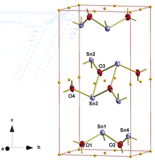
Figure 1.
Ball-and-stick model showing the crystal structure of the red SnO modification in P1 with atom labeling of the asymmetric unit and skeleton of inversion centers (orange spheres); atoms are drawn as thermal displacement ellipsoids of the 40% level; bonds to atoms outside the unit cell are indicated by shortened sticks.
The most important aspects of the resulting solution are as follows: (i) the crystal lattice is primitive and not c-centered, (ii) the structure is centrosymmetric and not non-centrosymmetric, (iii) all tin atoms are in trigonal pyramidal coordination, (iv) all oxygen atoms are trigonal-planar coordinated, and (v) the structure is a layer structure.
In order to check whether the primitive lattice is correct or not, the c-centered dataset was replaced by the triclinic one before refining the structure model of Cmc21 again. SHELX now advised that only 930 (before merging), or 4.9% of all measured reflections, are marked as systematic absence violations from 18.893 reflections rejected because of c-centering. This explains the initial assumption of c-centering. All marked reflections of systematic absence violations are very weak (I(hkl with h + k = 2n + 1)/Imax(200) ≤ 2.5%) but nevertheless of sufficient precision (I(0)/σ(I) = 5.60). For the most intense reflection (0) in this group of reflections, Imean achieves a value of 70.46 with σ(I) = 12.56 and I/σ(I) = 5.60. The difficulty in detecting those less intense reflections is proven by a simulated precession photograph, a detail of which is depicted in Figure 2.
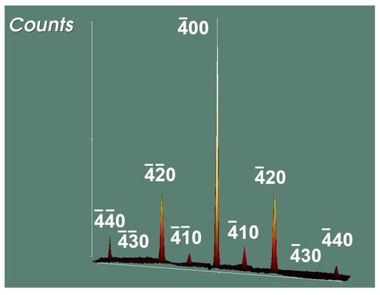
Figure 2.
Detail of the hk0-layer showing the intensity distribution of the 4k0-reflections to emphasize the weak intensities of reflections violating the extinction condition of c-centering = hkl only present for h + k = 2n.
The issue of the low intensities for reflections hkl with h + k = 2n + 1 and their detection in a powder diffractogram is illustrated in Figure 3, displaying a simulated powder diffractogram based on the structure model in Pbca (as shown below). Measured powder diffractograms of red SnO superimposed with the calculated ones for the structure models in Cmc21 are found in the literature [20,21].
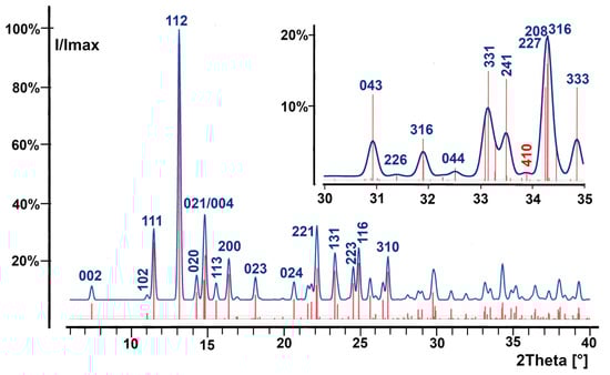
Figure 3.
Simulated powder diffractogram of red SnO in point group Pbca showing the low intensities of reflections hkl with h + k = uneven; the intensity distribution around reflection 410 (red) is enlarged in the insert; vertical bars (red) = reflections markers.
Furthermore, the centrosymmetric space group P matches well with the observed Flack parameter in Cmc21 and is very reliable. The anisotropic thermal displacement parameters of the atoms in the triclinic unit cell are unexpectedly uniform—this is unusual for refining a non-centrosymmetric structure within a centrosymmetric space group.
Last but not least, the correct space group in the higher symmetric (monoclinic or orthorhombic) crystal system has to be found. To undertake this task, there are several ways. In any case, one requirement has to be fulfilled: the skeleton of inversion centers in the new space group must be the same as in P.
In the past, this task was tackled manually, searching the symmetry relationships (mirror and glide planes, proper rotation, screw, and rotoinversion axes) between all atoms in the triclinic unit cell and comparing these symmetry elements with those listed in the International Tables [30]. This way of finding the additional symmetry elements is sketched out in Appendix A. The three orthogonal glide planes are compatible with the orthorhombic crystal system. They give rise to the extinction conditions 0kl only present for k = 2n, h0l only present for l = 2n, and hk0 only present for h = 2n, thus unambiguously indicating space group Pbca (no. 61 [30]).
Nowadays, a simpler way to find the correct space group is advised. This is achieved with the structure validation program checkCIF [33]. In the present case, this program recognizes the symmetry relationships of the atoms in P and recommends the orthorhombic space group Pbca, too.
Alternatively, one can use the Intrinsic Phasing subroutine (see above) to solve the structure in a primitive monoclinic (Laue class: 2/m; starting space group e.g., P21, resulting space group: P21/c (= subgroup of Pbca); validation via checkCIF > Pbca) or orthorhombic (Laue class: mmm; starting space group e.g., P212121, resulting space group: Pbca). In both cases, the choice of the primitive starting space group has no influence on the result.
Crystallographic data, data collection, and structure refinement parameters for the structure refinement of the red SnO modification in space group Pbca are summarized in Table 1. Additional tables of atomic coordinates (Table S11), bond lengths and angles (Table S12), and thermal displacement parameters (Table S13) are provided as Supplemental Materials. Details on the structure are described in Section 3.2.
3. Results
3.1. Blue-Black SnO
The SCXRD determination of the blue-black SnO-modification confirms the previous results of a layer structure consisting of two building units, one square-pyramidally, spy, coordinated tin and one tetrahedrally, tetr, coordinated oxygen atom (Figure 4).
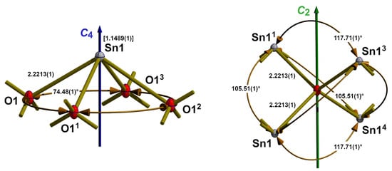
Figure 4.
Ball-and-stick models with bond lengths (Å), angles (°), and symmetry elements describing the coordination spheres of tin (left) and oxygen (right) in the crystal structure of the blue-black SnO modification at ambient temperature; bonds to adjacent atoms are indicated by shortened sticks; value in square brackets = distance of the tin atom above the basal plane; symmetry codes used to generate equivalent atoms: (1) −x + 1, −y, −z; (2) x − 1, y, z; (3) −x + 1, -y + 1, −z; (4) x + 1, y, z.
In the square pyramid of point group symmetry C4 (Figure 4 left), the tin atom forms the apex, situated 1.1489(3) Å above the basal plane of the four oxygen atoms. This coordination geometry is very unusual in tin chemistry but has its complement in the isostructural lead compound of red PbO modification litharge. However, square-pyramidal coordinated tin atoms have been observed in the case of the {RSnO4}-coordinated tin atoms within the monoorganotin(IV) oxo clusters of type [(RSn)12O14(OH)6]2+ [34].
With four Sn–O bond lengths of 2.2213(1) Å, which are slightly shorter (2.224(6) Å) than the values of Pannetier and Denes [10], a bond valence sum, BVS, of 2.01 is calculated using the values provided by Gagné and Hawthorne [22]. All bond angles within the {SnO4} building units of 74.48(1)° are in the same (74.4°) order as those in literature [10] but similar to the bond lengths of higher precision.
The oxygen atom exhibits a distorted tetrahedral coordination with point group symmetry C2 (Figure 4, right). Distortion of the {OSn4} tetrahedron results from its compression in the direction of the C2 rotation axis where the edge-to-edge distance amounts to 2.2978(1) Å, while the same values perpendicular to this axis are 2.6885(1) Å. This compression results in the observed bond angles of 117.84(1)° and 105.46(1)°. The corresponding values given by Pannetier and Denes [10] are 117.5° and 105.6° with values for the compression of 2.306/2.689 Å.
The square pyramidal [SnO4} units are cross-linked on all four edges of the basal plane, with the tin atoms (the apexes of the square pyramids) alternating below and above the plane of the oxygen atoms (Figure 5). This special connectivity of the primary building units results in layers composed of two outer tin planes and one oxygen plane in between (Figure 6). The complete layer has a thickness of 2.2857(3) Å, and the distance between two neighboring layers measures 2.5168(3) Å.
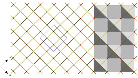
Figure 5.
Top view on a layer in the crystal structure of blue-black SnO visualizing the connection of the square-pyramidal {SnO4} coordination polyhedra as polyhedra (right halve) and ball-stick-models (left halve); unit cell in blue.
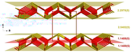
Figure 6.
Perspective view looking into the crystal structure of the blue-black SnO modification, with intra- and interlayer distances (Å); two-colored stick-model (tin = brassy, oxygen = red); bonds to adjacent atoms are indicated by shortened sticks; viewing direction = b-axis and unit cell in red.
At 100 K, the volume of the unit cell is 0.875 Å3 smaller than at ambient temperature. Shortening of the a-axis (−0.0099 Å) is less expressed than those of the c-axis (−0.0356 Å). Changes in the Sn–O bond lengths (2.2139(2) Å) are moderate (−0.0074 Å), as are those of the bond angles (+0.07°) in the {SnO4}spy polyhedra. Compression of the {OSn4} tetrahedra is more distinct in the direction of the c-axis (2.2857(2) Å, Δ = −0.0121 Å) than in the ab-plane (2.6815(2) Å, Δ = −0.007 Å).
Shortening of the c-axis is mainly due to shrinkage (−0.0235 Å) of the interlayer distances from 2.5402(5) Å to 2.5168(3) Å, while the layer itself contracts by 0.0121 Å from 2.2978(5) Å to 2.2857(3) Å. The position of the oxygen plane exactly in between both tin layers remains unaffected.
3.2. Red SnO
The two building units, one tin and one oxygen atom, of the red SnO modification are represented in Figure 7.
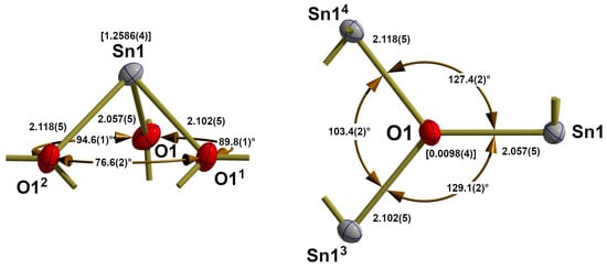
Figure 7.
Ball-and-stick models with bond lengths (Å) and angles (°) describing the coordination spheres of tin (left) and oxygen (right) in the crystal structure of red, orthorhombic SnO; bonds to adjacent atoms are indicated by shortened sticks; values in square brackets = distances of the central atoms above the basal planes; symmetry codes used to generate equivalent atoms: (1) x − ½, y − ½, z; (2) −x + ½, y − ½, z, (3) −x, y, z; (4) x + ½, y + ½, z.
In contrast to the tin atoms of blue-black SnO, those in the red modification are trigonal-pyramidally coordinated (Figure 7, left), with tin at the apex of the trigonal pyramid and 1.2586(4) Å above the basal plane of the three oxygen atoms. All three Sn–O bonds in this {SnO3}tpy coordination polyhedron are of different lengths ranging from 2.057(5) Å over 2.102(5) Å to 2.118(5) Å while bond angles measure 76.6(2)°, 89.8(1)°, and 94.6(2)° with the smallest one between the oxygen atoms with the longest bonds to the tin atom.
BVS calculations, according to Gagné and Hawthorne [22], give a value of 2.00 in agreement with the oxidation state of +II of the tin atom. There are no further tin-oxygen contacts, as the distance of 3.5703(2) Å to the next nearest oxygen atom (in the same layer, see below) is only marginally shorter than the sum (3.69 Å) of van der Waals radii [35] of tin (2.17 Å) and oxygen (1.52 Å).
Similarly, pure {SnO3}tpy coordination polyhedra are rare. Primarily, they have been observed in isopolyoxoanions, [SnIInOo(OH)p](2n−2o−p)−. Instead of μ3-O atoms, these coordination polyhedra are composed of μ1-OH groups and μ2-O atoms. Mononuclear (n = 1, o = 0, p = 3) [Sn(OH)3]− species with d(Sn–O) in the range of 2.045 – 2.099 Å and ∠(O−Sn−O) in the range of 84.1° – 91.1° in Na4[Sn4O(OH)10] = Na4[Sn(OH)3]2[Sn2O(OH)4] [36]. In the dinuclear (n = 2, o = 1, p = 4) [Sn2O(OH)4]2− species of this compound the tin atoms exhibit a {Sn(μ2-O)(μ1-OH)}tb coordination with d(Sn−OH) of 2.077–2.114 Å, and d(Sn−μ2O) = 2.004–2.026 Å, respectively, and ∠(O−Sn−O) = 85.7° – 92.9°. Similar values are observed in the dinuclear (n = 2, o = 2, p = 2) chain-like isopolyoxoanion of Ba[Sn2O2(OH)2] [37]
The oxygen atom of the red tin monoxide modification exhibits a distorted trigonal-planar, tpl, tin environment (Figure 7, right) featuring three different Sn–O bond lengths and angles. The deviation from planarity is given by a distance of 0.0098(4) Å between the oxygen atom and the plane formed by the three tin atoms. The primary source of distortion results from bond lengths (see above) and the bond angles of 127.4(2)°, 129.1(2)°, and 103.4(2)°. Such a broad-broad-narrow bond angle distribution (129.26(2)°, 129.26(2)°, 101.48(2)°) is also found in the case of μ3-coordinated oxygen atoms in SnIVO2, although its tin atoms are distorted octahedrally coordinated and exhibit shorter Sn–O bonds (2.0475(4), 2.0475(4), 2.0577(3) Å) [38].
Two {SnO3}tpy units are linked together via a common edge forming a four-membered, centrosymmetric tin–oxygen ring with narrow (76.6(2)°) angles at the oxygen and widened (103.4(2)°) one at the tin atom (Figure 8). In these dimeric building units, both tin atoms adopt positions below and above the plane formed by the six basal oxygen atoms.
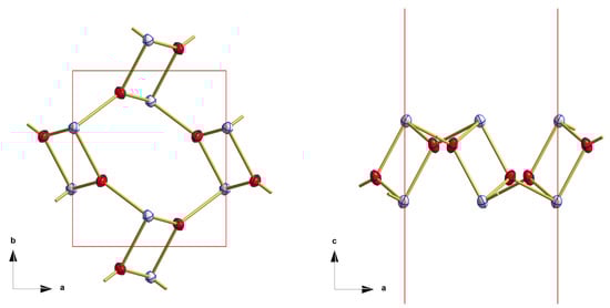
Figure 8.
Details of the layers observed in the crystal structure of red, orthorhombic SnO showing the linkage of the primary building units to dimers and their arrangement within layers; top view (left), side view (right); bonds to adjacent atoms are indicated by shortened sticks.
In contrast to the arrangement observed in blue-blue SnO, this configuration no longer repeats in the plane but is nearly perpendicular (interplanar angle: 86.5°) to each other, giving each layer the complex appearance of Figure 9.
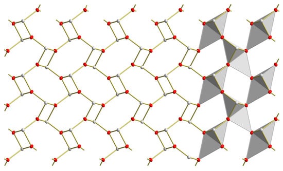
Figure 9.
Top view on a layer in the crystal structure of red SnO visualizing the connection of the trigonal-pyramidal {SnO3} coordination polyhedra as polyhedra (right halve) and ball-stick-models (left halve).
In the layers, the oxygen atoms are arranged in two different separate planes between two planes of tin atoms (Figure 10). Within a layer, the distances between the planes of the tin atoms come to 2.6410(6) Å, and between two layers, to 2.8890(6) Å. In the layers, the planes of the oxygen atoms are distanced by 0.7880(6) Å from the planes of the tin atoms (Figure 10).
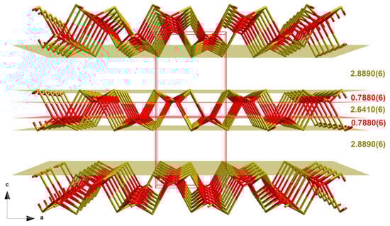
Figure 10.
Perspective view into the crystal structure of the red SnO modification with intra- and interlayer distances [Å]; two-colored stick-model (tin = brassy, oxygen = red); bonds to adjacent atoms are indicated by shortened sticks; viewing direction = b-axis and unit cell in red.
From a topological perspective, the single crystal structure of red SnO resembles in many details the structure computed with different methods by Li et al. [27] of tin monoxide at a pressure of 0 GPa. In the layers of this predicted structure, the tin atoms exhibit trigonal-pyramidal coordination, while the oxygen atoms show trigonal-planar coordination featuring very similar bond lengths (2.068, 2.103, 2.128 Å) and angles (Sn: 76.6°,91.3°, 93.1°; O: 103.4°, 130.0°, 126.4°). Each layer has a thickness of 2.666 Å with two oxygen planes 0.7687 Å below and above the outer tin planes, while the interlayer distances measure 2.8013 Å. Differences mainly arise from the fact that the volume of the computed monoclinic unit cell of space group P21/c constitutes half the value of the observed one with a monoclinic angle of 101.39°.
4. Experimental
Single crystals suitable for X-ray measurements were selected under a microscope and mounted on a 50 μm MicroMesh MiTeGen MicromountTM using FROMBLIN Y perfluoropolyether (LVAC 16/6, Aldrich). Subsequently, they were centered on a Bruker Kappa APEX II CCD-based 4-circle X-ray diffractometer. This diffractometer employed graphite monochromated Mo Kα radiation (λ = 0.71073 Å) sourced from a fine-focus molybdenum-target X-ray tube operating at 50 kV and 30 mA. The crystal-to-detector distance was 40 mm, and the scan width was 0.5°. Exposure times are given in Table 1. Cooling of the single crystal of blue-black SnO to 100 K was achieved using a Kryoflex low-temperature device.
Initial unit cell parameters were obtained by least-squares refinement of the xyz centroids of strong reflections harvested from a series of 12 frames in each of three orthogonally related regions of the reciprocal space. This refinement was performed using the Evaluate routine within the APEX 3 software suite [32]. Final unit cell parameters were calculated at the end of intensity measurements utilizing the xyz centroids of up to 10,000 well-centered intense reflections of the complete data set.
Integrated intensities were obtained with the Bruker SAINT [39] software package using a narrow-frame algorithm performing spatial corrections of frames, background subtractions, Lorenz and polarization corrections, profile fittings, and error analyses. Semi-empirical absorption corrections based on equivalent reflections were made by use of the program SADABS [40]. Data were integrated and scaled using the programs SAINT and SADABS [41] within the APEX 3 software package of Bruker [32]. Special care was taken regarding the data collection strategy in order to reduce absorption effects. A maximum reduction of absorption effects and remaining electron density was achieved by high data redundancy and empirical absorption corrections. Details on the data collection parameters applied on the individual crystals are summarized in Table 1 with Rint = Σ|Fo2 − Fo2(mean)|/Σ[Fo2] and Rsigma = Σ[σ(Fo2)]/Σ[Fo2]
Structures were solved by direct methods of SHELXS ([42]) and completed by difference Fourier synthesis with SHELXL [42]. Structure refinements were carried out on F2 using full-matrix least-squares procedures, applying anisotropic thermal displacement parameters. Atomic scattering factors were taken from International Tables for Crystallography [43].
Final agreement indices: R1 = Σ||Fo| − |Fc||/Σ|Fo| and wR2 = [Σ[w(Fo2 − Fc2)2]/Σ(Fo2)2]]1/2. Weighting function used: w = 1/[σ2(Fo2) + (aP)2 + bP] with P = [2Fc2 + Max(Fo2,0)]/3. Goof = [Σ[w(Fo2 − Fc2)2]/(n − p]1/2 where n is the number of reflections and p is the total number of parameters refined.
Figures have been drafted by use of DIAMAND [44] and realized by POV-Ray [45]. In the ball-and-stick models, all atoms are drawn as thermal displacement ellipsoids of the 40% level, except for the low-temperature measurement of blue-black SnO, where a 70% level was applied.
Powder simulation has been performed by use of DIAMOND with corrections to Lorentz and polarization factors applying a Gaussian profile with a 2Θ-steps of 0.03° fitting; intensities were scaled to Imax = 100%.
Further details of the crystal structure investigations may be obtained from the joint CCDC/FIZ Karlsruhe online deposition service: www.ccdc.cam.ac.uk/structures (accessed on 31 March 2023) by quoting the deposition numbers CSD-2284871 for blue-black SnO at 100 K, CSD-2284941 for blue-black SnO at ambient temperature, and CSD-2284869 for red SnO.
Details on the crystallographic data, data collection parameters, and results of structure refinement are summarized in Table 1.
5. Conclusions
Our single crystal structure determinations of the blue-black, tetragonal SnO modification confirm the previous results from powder diffraction analysis of a layer structure with square pyramidally coordinated tin and distorted tetrahedrally coordinated oxygen atoms. The determinations improve the precision of the structural parameters significantly. Moreover, they show that the structure is stable up to 100 K without a phase transition.
The detailed analysis of the data set obtained during the single crystal structure determination of the red orthorhombic SnO modification establishes a primitive orthorhombic lattice of this modification, in contrast to the previously assumed c-centered one. In the correct orthorhombic space group, Pbca, the layer structure consists of very regular trigonal-pyramidally coordinated tin and trigonal-planar coordinated oxygen atoms with structural parameters in very good agreement with bond valence calculations.
Moreover, the paper demonstrates ways (measuring a triclinic data set, simulating precession images) and highlights tools (structure solution in P1, Intrinsic phasing, validation of given structure models by different programs) for surmounting the difficulties of space group determination arising from low reflection intensities due to microcrystals.
Supplementary Materials
The following supporting information can be downloaded at: https://www.mdpi.com/article/10.3390/cryst13081281/s1, Table S1: Atomic coordinates of blue-black SnO at ambient temperature; Table S2: Bond lengths and angles of blue-black SnO at ambient temperature; Table S3: Anisotropic thermal displacement parameters of blue-black SnO at ambient temperature; Table S4: Atomic coordinates of blue-black SnO at 100 K; Table S5: Bond lengths and angles of blue-black SnO at 100 K, Table S6: Anisotropic thermal displacement parameters of blue-black SnO at 100 K; Figure S1. Unit cell of red SnO in Cmc21; Table S7: Crystallographic data of red SnO in Cmc21; Table S8: Atomic coordinates of red SnO in Cmc21; Table S9: Bond lengths and angles of red SnO in Cmc21; Table S10: Anisotropic thermal displacement parameters of red SnO in Cmc21; Table S11: Atomic coordinates of red SnO in Pbca; Table S12: Bond lengths and angles of red SnO in Pbca; Table S13: Anisotropic thermal displacement parameters of red SnO in Pbca.
Funding
This research received no external funding.
Data Availability Statement
Data are contained within the article or Supplementary Materials.
Acknowledgments
We thank the Deutsche Forschungsgemeinschaft and the Government of Lower Saxony for funding the diffractometer and acknowledge support by Deutsche Forschungsgemeinschaft (DFG).
Conflicts of Interest
The author declares no conflict of interest.
Appendix A. Manual Evaluation of Space Group Symmetry from the Triclinic Solution
In order to evaluate the symmetry relationships, all atoms in the triclinic unit cell have to be taken into account. In the present case, half of the atoms are related to the others through centers of symmetry (Figure 1) which are already given by the space group symmetry of P. The principal difficulty in the next step of the search for further symmetry elements lies in the selection of an appropriate asymmetric unit to recognize the symmetry relationships in a simple way. Such an appropriate asymmetric unit is most often not given by the structure solution program but can be easily checked by hand switching between the coordinates of a given atom and its center of symmetry-related counterpart. This is already accomplished in Table A1.
Additional symmetry elements like mirror planes, rotation, and screw axes or glide planes can now be derived by analyzing the atom coordinates. When an axial glide plane is positioned between two atoms, its translation component introduces half of a translation vector, while its second component, the mirror plane, preserves one coordinate and alters the second one based on the mirror plane’s placement within the unit cell. For the triclinic solution of red SnO, these corresponding considerations are summarized in Table A1 and visualized in Figure A1.
Table A1.
Atoms of the asymmetric unit in the triclinic solution of red SnO and their symmetry relationships.
Table A1.
Atoms of the asymmetric unit in the triclinic solution of red SnO and their symmetry relationships.
| Atom | Coordinates | Glide Planes | ||||
|---|---|---|---|---|---|---|
| x | y | z | operation | location | translation | |
| Sn(1) | 0.0084 = x | 0.3262 = y | 0.1194 = z | |||
| Sn(2) | 0.0084 | 0.1737 | 0.6194 | x, ½ − y, ½ + z | x, ¼, z | c |
| Sn(3) | 0.5083 | 0.3261 | 0.3807 | ½ + x, y, ½ − z | ¼, y, z | a |
| Sn(4) | 0.4915 | 0.8262 | 0.1194 | ½ − x, ½ + y, z | x, y, ¼ | b |
| O(1) | 0.3108 = x | 0.1257 = y | 0.0479 = z | |||
| O(3) | 0.3105 | 0.3741 | 0.5476 | x, ½ − y, ½ + z | x, ¼, z | c |
| O(2) | 0.1898 | 0.6264 | 0.0482 | ½ − x, ½ + y, z | x, y, ¼ | b |
| O(4) | 0.8124 | 0.1268 | 0.4528 | ½ + x, y, ½ − z | ¼, y, z | a |
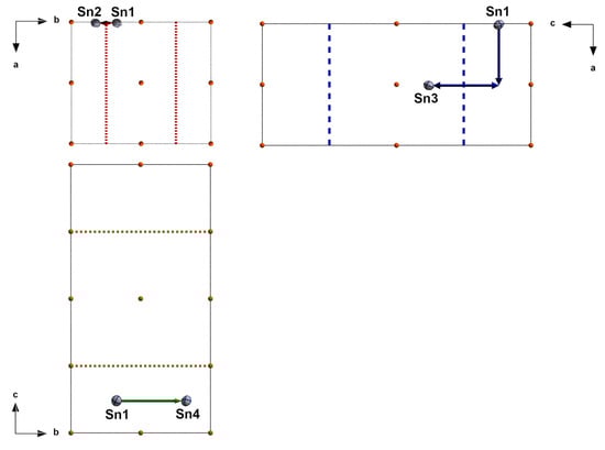
Figure A1.
Visualization of the symmetry transformations (glide planes) transferring Sn1 to Sn2, Sn3, and Sn4 in the triclinic solution of red SnO; in the different projections, only the glide planes according to Table A1 are drawn; for comparison, projections have been chosen and arranged according to the convention of the International Tables [30]; glide plane with translation component normal to projection plan = dotted line; glide plane with translation component along line in projection plane = dashed line.
References
- Proust, J.L. Recherche sur l’étain. J. Phys. Chim. Hist. Nat. Arts 1800, 51, 173–184. [Google Scholar]
- Berzelius, J.J. Des oxides d’étain et de tellure. Ann. Chim. Ser. 1 1813, 87, 50–97. [Google Scholar]
- Gay-Lussac, J.L. Sur l’Oxidation de quelques métaux. Ann. Chim. Phys. Ser. 2 1816, 1, 32–45. [Google Scholar]
- Frémy, E. Recherches sur les acides métalliques. Compt. Rend. Hebd. 1842, 15, 1106–1111. [Google Scholar]
- Roth, R. Ueber das rothe Zinnoxydul. Jahrb. Prakt. Pharm. 1845, 10, 381–382. [Google Scholar]
- Weiser, H.B.; Milligan, W.O. X_Ray Studies on the Hydrous Oxides III. Stannous Oxid. J. Phys. Chem. 1932, 32, 3039–3045. [Google Scholar] [CrossRef]
- Levi, G.R. Isomorfismo degli ossidi stannoso e piomboso. Nuovo Cimento 1924, 1, 335–346. [Google Scholar] [CrossRef]
- Straumanis, M.; Strenk, C. Über das Zinn(2)-Oxyd. Z. Anorg. Allg. Chem. 1933, 213, 301–309. [Google Scholar] [CrossRef]
- Moore, W.J.; Pauling, L. The Crystal Structure of the Tetragonal Monoxides of Lead, Tin, Palladium, and Platinum. J. Am. Chem. Soc. 1941, 63, 1392–1394. [Google Scholar] [CrossRef]
- Pannetier, J.; Denes, G. Tin(II) Oxide: Structure Refinement and Thermal Expansion. Acta Cyrstallogr. 1980, B36, 2763–2765. [Google Scholar] [CrossRef]
- Izumi, F. Pattern-Fitting Structure Refinement of Tin(II) Oxide. J. Sol. State Chem. 1981, 38, 381–385. [Google Scholar] [CrossRef]
- Herber, R.H. Mössbauer lattice temperature of tetragonal (P4/nmm) SnO. Phys. Rev. 1983, B27, 4013–4017. [Google Scholar] [CrossRef]
- Moreno, M.S.; Mercader, R.C. Mössbauer study of SnO lattice dynamics. Phys. Rev. 1994, B50, 9875–9881. [Google Scholar] [CrossRef] [PubMed]
- Boher, P.; Garnier, P.; Gavarri, J.R.; Hewat, A.W. Monoxyde quadratique PbOα(I): Description de la transition structurale ferroe´lastique. J. Solid State Chem. 1985, 57, 343–350. [Google Scholar] [CrossRef]
- Organ, R.M.; Mandarino, J.A. Romarchite and hydroromarchite, two new stannous minerals (Abstract). Can. Mineral. 1971, 10, 916. [Google Scholar]
- Warr, L.N. IMA-CNMNC approved mineral symbols. Miner. Mag. 2021, 85, 291–320. [Google Scholar] [CrossRef]
- Donaldson, J.D.; Moser, W.; Simpson, W.B. Red Tin(II) Oxide. J. Chem. Soc. 1961, 839–841. [Google Scholar] [CrossRef]
- Hill, P.A. Refinement of the structure of orthorhombic PbO (massicot) by Rietveld analysis of neutron powder diffraction data. Acta Cryst. 1985, C41, 1281–1284. [Google Scholar] [CrossRef]
- Donaldson, J.D.; Moser, W.; Simpson, W.B. The structure of the red modification of tin(II) oxide. Acta Cryst. 1963, 16, A22. [Google Scholar]
- Köhler, J.; Tong, J.; Dinnebier, R.E.; Simon, A. Crystal Structure and Electronic Structure of Red SnO. Z. Anorg. Allg. Chem. 2012, 638, 1970–1975. [Google Scholar] [CrossRef]
- Wittmann, S.; Murshed, M.M.; Gesing, T.M. On red tin (II) oxide: Temperature-dependent structural, spectroscopic, and thermogravimetric properties. Z. Anorg. Allg. Chem. 2022, 648, e202200311. [Google Scholar] [CrossRef]
- Gagné, O.C.; Hawthorne, F.C. Comprehensive derivation of bond-valence parameters for ion pairs involving oxygen. Acta Cryst. 2015, B71, 562–578. [Google Scholar] [CrossRef] [PubMed]
- Walsh, A.; Watson, G.W. Electronic structures of rocksalt, litharge, and herzbergite SnO by density functional theory. Phys. Rev. 2004, B70, 235114. [Google Scholar] [CrossRef]
- Allen, J.P.; Scanlon, D.O.; Parker, S.C.; Watson, G.W. Tin Monoxide: Structural Prediction from First Principles Calculations with van der Waals Corrections. J. Phys. Chem. C 2011, 115, 19916–19924. [Google Scholar] [CrossRef]
- Zhou, W.; Umezawa, N. Band gap engineering of bulk and nanosheet SnO: An insight into the interlayer Sn-Sn lone pair interactions. Phys. Chem. Chem. Phys. 2015, 17, 17816–17820. [Google Scholar] [CrossRef] [PubMed]
- Mubeen, A.; Majid, A.; Alkhedher, M.; Tag-ElDin, E.M.; Bulut, N. Structural and Electronic Properties of SnO Downscaled to Monolayer. Materials 2022, 15, 5578. [Google Scholar] [CrossRef] [PubMed]
- Li, K.; Wang, J.-Q.; Blatov, V.A.; Gong, Y.; Umezawa, N.; Tada, T.; Hosono, H.; Oganov, A.R. Crystal and electronic structure engineering of tin monoxide by external pressure. J. Adv. Ceram. 2021, 10, 565–577. [Google Scholar] [CrossRef]
- Allen, J.P.; Scanlon, D.O.; Piper, L.F.J.; Watson, G.W. Understanding the defect chemistry of tin monoxide. J. Mater. Chem. C 2013, 1, 8184–8208. [Google Scholar] [CrossRef]
- Miller, S.A.; Gorai, P.; Aydemir, U.; Mason, T.O.; Stevanović, V.; Toberer, E.S.; Snyder, G.F. SnO as potential thermoelectric candidate. J. Mater. Chem. C 2017, 5, 8854–8861. [Google Scholar] [CrossRef]
- Hahn, T. International Tables for Crystallography, 4th ed.; Vol. A—Space-Group Symmetry; Kluwer Academic Publishers: Dordrecht, The Netherlands, 1996. [Google Scholar]
- Sheldrick, G.M. SHELXT—Integrated space-group and crystal structure determination. Acta Cryst. 2015, A71, 3–8. [Google Scholar] [CrossRef]
- Bruker. APEX 3—Suite of Crystallographic Software, 2015.9, ed.; Bruker: Madison, Wisconsin, USA, 2015. [Google Scholar]
- Spek, A.L. checkCIF validation ALERTS: What they mean and how to respond. Acta Cryst. 2020, E76, 1–11. [Google Scholar] [CrossRef] [PubMed]
- Puff, H.; Reuter, H. Zur Hydrolyse von Monoorganylzinn-trihalogeniden III. Isolierung und Röntgenstrukturanalyse von Verbindungen mit dem neuartigen Käfig-Ion [(i-PrSn)12O14(OH)6]2+. J. Organomet. Chem. 1989, 373, 173–184. [Google Scholar] [CrossRef]
- Mantina, M.; Chamberlin, A.C.; Valero, R.; Cramer, C.J.; Truhlar, D.G. Consistent van der Waals Radii for the Whole Main Group. J. Phys. Chem. A 2009, 113, 5806–5812. [Google Scholar] [CrossRef] [PubMed]
- Schnering, H.G.V.; Nesper, R.; Pelshenke, H. Hydroxoverbindungen. 10. Über die Natriumoxohydroxostannate(II) Na4[Sn4O(OH)10] und Na2[Sn2O(OH)4]. Z. Anorg. Allg. Chem. 1983, 499, 117–129. [Google Scholar] [CrossRef]
- Nesper, R.; von Schnering, H.G. Barium-Oxohydroxostannat(II) Ba[SnO(OH)]2. Z. Anorg. Allg. Chem. 1983, 499, 109–116. [Google Scholar] [CrossRef]
- Bolzan, A.A.; Fong, C.; Kennedy, B.J.; Howard, C.J. Structural Studies of Rutile-Type Metal Dioxides. Acta Cryst. 1977, B53, 373–380. [Google Scholar] [CrossRef]
- Bruker. SAINT, 7.56a; Bruker AXS Inc.: Madison, WI, USA, 2008. [Google Scholar]
- Bruker. SADABS, 2008.1; Bruker AXS Inc.: Madison, WI, USA, 2008. [Google Scholar]
- Krause, L.; Herbst-Irmer, R.; Sheldrick, G.M.; Stalke, D. Comparison of silver and molybdenum microfocus X-ray sources for single-crystal structure determination. J. Appl. Cryst. 2015, 48, 3–10. [Google Scholar] [CrossRef] [PubMed]
- Sheldrick, G.M. A short history of SHELX. Acta Cryst. 2015, C71, 3–8. [Google Scholar] [CrossRef]
- Wilson, A.J.C. (Ed.) International Tables for Crystallography; Kluwer Academic Publishers: Dordrecht, The Netherland, 1992; Volume C. [Google Scholar]
- Brandenburg, K. Diamond—Crystal and Molecular Visualization; Crystal Impact: Bonn, Germany, 2006. [Google Scholar]
- POV-Ray—Persistence of Vision Raytracer, Version 3.7; Persistence of Vision Pty. Ltd.: Williamstown, VIC, Australia, 2004; Available online: http://www.povray.org/download/ (accessed on 31 March 2014).
Disclaimer/Publisher’s Note: The statements, opinions and data contained in all publications are solely those of the individual author(s) and contributor(s) and not of MDPI and/or the editor(s). MDPI and/or the editor(s) disclaim responsibility for any injury to people or property resulting from any ideas, methods, instructions or products referred to in the content. |
© 2023 by the author. Licensee MDPI, Basel, Switzerland. This article is an open access article distributed under the terms and conditions of the Creative Commons Attribution (CC BY) license (https://creativecommons.org/licenses/by/4.0/).