Abstract
Composite laminated bolted joints are increasingly used in the aerospace industry, and most researchers are involved in the study of the failure behavior of composite bolted joints’ structures. Because of the complexity and stability of the structure, precisely predicting the damage evolution and failure behavior of the composite laminated bolted joint becomes rather difficult. In this paper, an asymptotic damage model is proposed to predict the failure behavior of the composite bolted joint structure. The model is based on the frame of mainstream criteria and some improvements are made to adapt to the particularity of composite laminated bolted joints. Combining the damage model with the finite element method, the failure behavior of single-lap and double-lap bolted joint structures are predicted and analyzed. In order to guarantee the reliability of the model, the corresponding experimental study is conducted, and the results show that the simulation curve and the experimental data are in good agreement. This damage model can further predict the failure behavior of various types of complex composite laminated bolted joints effectively.
1. Introduction
Advanced fiber-reinforced composite structures have been increasingly applied in aerospace, vehicles, astronautics and other various industrial fields due to their excellent performance, including high specific stiffness, high specific strength and good resistance to fatigue and corrosion coupled with excellent structural integrity [1]. Many research results have reported on the mechanical properties of composite materials [2,3,4]. Meanwhile, the composites exhibit various and complex failure behaviors. Especially, the failure behavior of composite laminated bolted joints is very complicated and important. In many cases, a composite laminated bolted joint is the vital and dangerous part in composite structure analysis. The existence of the stress concentration and the boundary effects may result in the damage and failure of the composite laminated bolted joint.
Different theories have been used to predict the failure behavior of composite structures. However, a set of complete and validated methods for predicting the progressive damage and failure behavior of composite laminated bolted joints has not been fully achieved yet. This paper mainly focuses on the failure behavior of the composite laminated bolted joint under quasi-static loading by combining the damage model and the finite element method.
Researchers have extensively investigated the mechanical properties of composite bolted structures, combining experimental and simulation methods. Wang et al. [5] studied the bearing failure of double-lap bolted composite joints through experimental characterization and analytical prediction, respectively. Vadean et al. [6] developed a fast and precise numerical calculation method to deal with the bolted joint for very large bearings. Both numerical and experimental studies were carried out by Veisi et al. [7] to study the strength and the bearing damage propagation of composite double-bolted joints. The effects of different moments and assembly clearances on the structural load-bearing mechanism of composite single-lap bolted joints were investigated by Liu [8] using a combination of theory, experiments and simulations.
Liu et al. [9] proposed a variable stiffness spring surface mode, calculated the strain and kinetic energy of the composite plate based on the classical laminate theory, derived the equations of motion of the structure by the Rayleigh–Ritz method and verified the efficiency of the model by comparing the results of experimental and 3D finite element model calculation. A model capable of predicting the ultimate strength of composite laminates with arbitrary layup orientation in tensile or shear failure modes was proposed by Chang et al. [10]. Ehk [11] investigated the effects of secondary bending on composite bolted structures and found that it may cause changes in ultimate strength and failure modes. Montagne et al. [12] analyzed single-layer bolted structures with different end distances by XR computed tomography (XR-CT) and digital image correlation (DIC). The results are compared with a three-dimensional finite element progressive damage model.
Catalanotti [13] proposed a method to predict the tensile failure of composite bolted structures. The critical initial damage load is predicted by a three-dimensional finite element model and the delamination is simulated with cohesive elements.
A damage analysis model based on the Puck/LaRC criterion and the nonlinear stiffness degradation method was developed by Li et al. [14] and experimentally verified. In addition, a method that can determine the fracture angle more accurately and quickly was proposed. Qin [15] described the strength, stiffness and failure modes of composite bolted structures with convex and countersunk, and revealed the influence of different fasteners on the mechanical behavior of composite bolted joints. Gray [16] experimentally investigated the effects of thickness, laminate taper and secondary bending on the stiffness, strength and failure modes of composite laminated bolted joint.
Models were proposed for the study of composite bolted joint structures. Xiao et al. [17,18] proposed a progressive damage model based on Hashin and Yamada-Sun’s hybrid failure criteria and a degradation model to predict the experimental result. Dano et al. [19] developed a finite element model to predict the response of pin-loaded composite plates. Thomas [20] developed three-dimensional finite element models capable of predicting stress distribution near bolt holes in composite bolted structures.
Wang et al. [21] developed a three-dimensional progressive damage model considering the orientation of the matrix crack, the closure effect of the matrix crack and the longitudinal compression response of the material under transverse restraint that has high accuracy and precision. Ahmad [22] developed a three-dimensional finite element damage and fracture model for woven composites using the extended finite element method, considering the effects of laminate lay-up, joint geometry, hole size and bolt clamping torque on structural strength and toughness, which were also tested experimentally. Stocchi [23] presented a finite element model of a single-ply composite bolted joint. The stress states of the composite and bolts, as well as the variation of the contact between the bolts and the holes under static tensile loading, was analyzed and compared with experimental results. Egan [24] formulated a three-dimensional composite damage model including the Puck criterion, nonlinear shear law and crack zone model, which improved the prediction of failure.
Mehmood et al. [25] developed two progressive failure damage models using Abaqus and Fortran to determine the failure of single and double nailed composite bolted structures with different geometric parameters according to the Maximum Stress failure criterion and the Yamada-Sun failure criterion.
There are various methods to study material fracture, and some scholars also developed phase-field models and validating peridynamic models to study the damage and destruction of brittle materials by the crack propagation approach [26]. A failure prediction method for composite bolted double-lap structures considering the influence of multiple factors was proposed by Li [27], which was based on a single-parameter spring-based method, a failure envelope method and a Monte Carlo simulation.
Generally, the failure modes of composite laminated bolted joints include net tension, shear-out, bearing and so on. The net tension and shear-out failure modes are both sudden catastrophic ones and tensile and shear failure is known as a brittle failure mode. Bearing failure, by contrast, is a slow and gradual failure process which is known as the plastic failure mode. Usually, designers expect the bearing failure mode to occur eventually in bolted joint structures. The bearing failure mode of composite laminated bolted joint structures can be detected in advance, thus obtaining a higher certain safety factor and avoiding catastrophic accidents. In view of this, bearing failure mode is very typical in practical engineering, which is the concentration in this paper.
The bolted lap laminate joints’ bearing failure mode can be represented by double-lap and single-lap laminate bolted joints. The stress in the vicinity of the bolt hole of double-lap laminate bolted joints should be more uniform than that of the single-lap. The non-uniform stress distribution in the vicinity of the bolt hole through the thick direction of the laminate can lead to a lot of difference between two joint ways.
In this paper, a set of three-dimensional detailed finite element progressive damage modeling methods is developed to predict the failure behavior of the composite laminated bolted joint structure. In addition, the experimental study of single-lap and double-lap bolted structures under tensile load is carried out, and the experimental data are compared with the model prediction results to verify the reliability of the proposed model. The model is divided into two parts, namely, the initial damage model and the progressive degradation model. The Max Stress criteria and Puck criterion are combined and used in the initial damage accumulation model. The progressive degradation model is applied to describe the process from initial damage onset to eventual failure. The continuous degradation factor is used to describe the failure behavior of the laminates. When the initial damage onset is detected by the initial damage criterion, the degradation of the property of the damaged element occurs, leading to the gradual loss of bearing capacity of the bolted joint structure.
The three-dimensional progressive damage finite element model established in this paper can effectively predict the damage and failure behavior of the composite laminate bolted structure. The use of Puck’s criterion makes it consider the influence of the fracture surface in judging the material damage, which provides a new perspective for studying the mechanical properties of the composite laminate bolted structure.
2. Initial Damage Model
2.1. Damage Variable
In this paper, the damage factor is introduced to characterize the damage degree. When the material is undamaged, the damage factor is zero. Then, the damage factor becomes greater than zero as the material’s initial damage appears. As the damage accumulates, the damage factor increases and reaches one, when the material fails completely.
Composite single-layer plates can be regarded as a kind of transverse isotropic material. The constitutive equation can be written as:
where is flexibility matrix, which has the following form:
where subscript 1 represents the longitudinal direction of fiber, subscript 2 represents the transverse direction of fiber. , , , , , , , , are elastic constants of fiber, are damage factors of different damage forms [28,29]. Damage factor is relative to the longitudinal rupture of fiber. and are relative to the transverse rupture of the single-layer plate. and are relative to fiber rupture and inter-fiber rupture of the single-layer plate. is influenced by the inter-fiber rupture of the single-layer plate.
2.2. Initial Damage Criteria
Although unavoidable initial defects such as micromechanical voids or cracks always exist in a composite material, it will not lose its loading capacity immediately. However, the initial damage will develop and result in catastrophic failure with sustained increasing load. Therefore, it is essential to propose a reasonable and accurate initial damage criterion to predict the damage position of the composite. In this paper, Puck’s theory [30] is selected as the initial damage criteria of the single-layer plate to characterize the damage in different positions and directions of the plate.
The loading function is a measurement of the damage, the value of which is zero when the material is undamaged and one when the initial damage occurs. The stress in the expression is not a damage stress unless the left part of the loading function is equal to one. The left part of the loading function is a risk parameter means that the stress vector taken with the reciprocal of can lead to initial damage. The load equations generally have the following forms:
Composite monolayers can be considered to be transversely isotropic at the macro scale, although they are constituted by an epoxy resin matrix and distributed fibers at the micro scale. The longitudinal and transverse damage behaviors of composite single-layer plates need to be considered in the initial damage criteria. The transverse moduli and are equal, namely . The composite materials have different properties between the tensile and compressive loadings both in the longitudinal and transverse orientations.
The loading function is concluded as follows:
The loading function of the composite material in direction 2 and direction 3 can be expressed as follows Zhong [28].
where and are the longitudinal tension and compression strengths of fiber, separately. The is the angle of the most dangerous plane of fiber transverse damage. Therefore, and is the load equation in this most dangerous scenario. Details refer to [28].
3. Progressive Degradation Model
The progressive damage model means that the material damage is an asymptotic process rather than an instantaneous process. The initial damage criterion is just the beginning; the more significant issue is the evolution of the damage. In many cases, the damage evolution laws determine the final strength and failure modes of the composite materials. In this paper, a combination of linear and exponential damage evolution and degradation laws are developed.
3.1. Expression of Evolution Law
The fiber damage threshold factors are written as follow:
where is the loading equation. From the Equation (9), we can know whether the materials are undamaged or not, and damage accumulates when inequality . In the equation, the subscripts t and c represents tension and compression, respectively. The formulation of the damage factors is expressed as following:
where is damage degeneration factor which is obtained through a complex calculation process. is affected by many material properties which are difficult to confirm. An exponential damage evolution model is used to describe the degradation of the fiber bundle properties, and the damage factors expression of the fiber bundle are as follows:
The damage of composite material is not independent in each direction, such as transverse damage of will lead to the degradation of longitude material properties. Therefore, considering the interaction of the performance damage in each direction, the damage factors can be written as follows:
where the parameter represents the damage of j direction contributing to the damage of i direction. The damage influence parameter can be determined by the combination of experiment and experience.
As introduced previously, the damage factor, , and , can be written as:
3.2. Damage Evolution Termination Condition
As the damage evolves, the damage factor increases monotonically with the increasing load. The damage factor increasing to one means that the material loses its bearing capacity completely. Actually, the damage factor cannot be one, because the denominator of the elements in the softened matrix cannot be zero, which is meaningless. On the other hand, the damage factor is not always increased to one since the composite material in transverse orientation can still bear the compressive load after crushing, where the damage factor is not increased to one and the stiffness of materials is not zero [8,30]. As greater degradation of stiffness occurs, the material will experience greater deformation, which is inconsistent with the actual material properties. Therefore, it is assumed that when material damage accumulates to a certain extent, the material properties will remain constant for a certain period of time due to the redistribution of stress. After that, with further increase in load, the material properties continue to degrade and finally fail completely, at which point the material is considered to have completely lost its load-bearing capacity and the unit is removed.
Of course, the property and morphology of the material have already changed after crushing. In order to simulate the behavior of the material during the full process, the residual stiffness is used to describe the properties of the material after crushing. The material will eventually maintain certain properties regardless of the applied load.
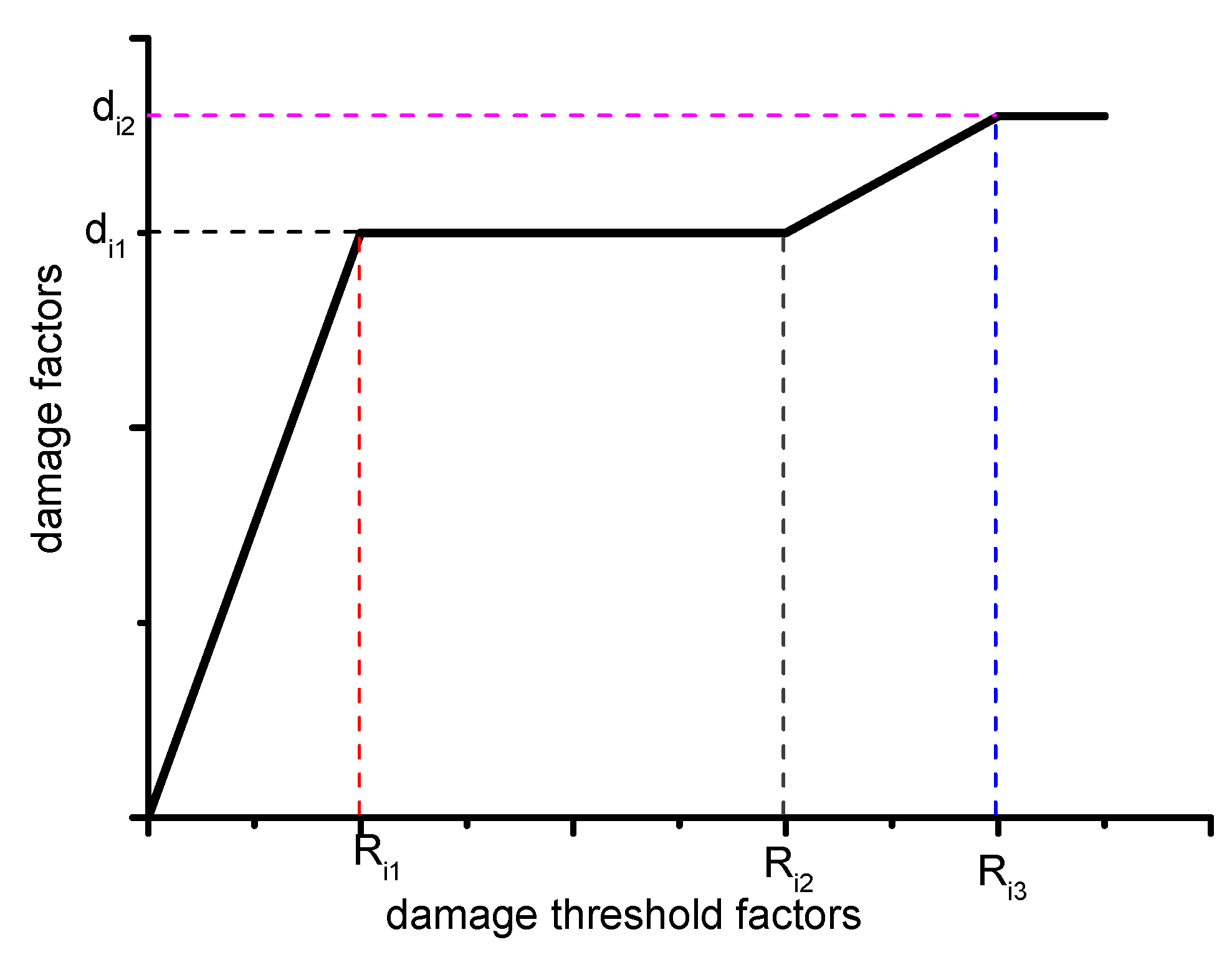
The damage factors di and the damage threshold factors Ri are used to control the damage process of the material, as shown in Figure 1. For the material under compressive loading, property degradation can be divided into two stages. In the first stage, the material property degrades increasingly to a critical value and keeps the property at a constant value [30,31].
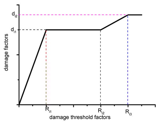
Figure 1.
Damage factors evolution process.
Stage 1:
In stage 2, the stiffness of the material reaches the maximum and remains. When the load increases, the stiffness of the material will continue degrading.
Stage 2:
where and is the second critical condition. represents further degradation of the material property.
After failure, the stiffness of the material will completely lose and decrease to zero, while in the damage model, a set of relatively small values are used instead of zero to express the material property. The crucial parameters in the damage evolution laws are given in Table 1. These sensitive parameters in Table 1 are related to the damage process in the late stages of material destruction and were obtained empirically based on the results of limited previous extrusion and pull-off experiments combined.

Table 1.
The critical parameters in the damage evolution laws.
4. Modeling and Finite Element Implementation
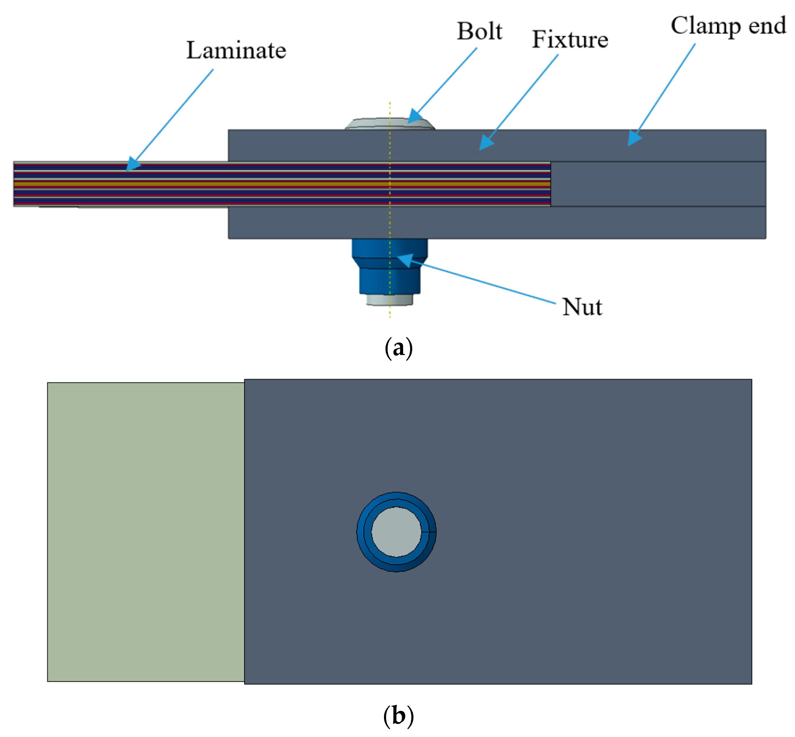
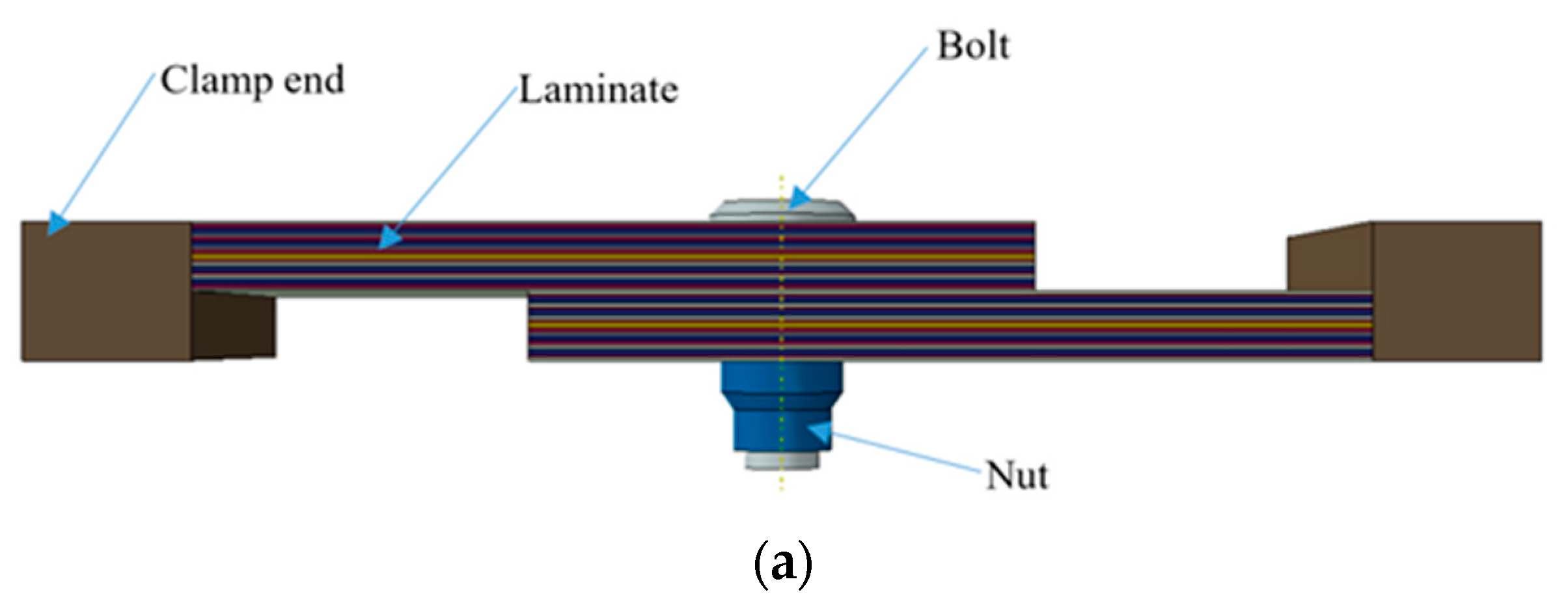
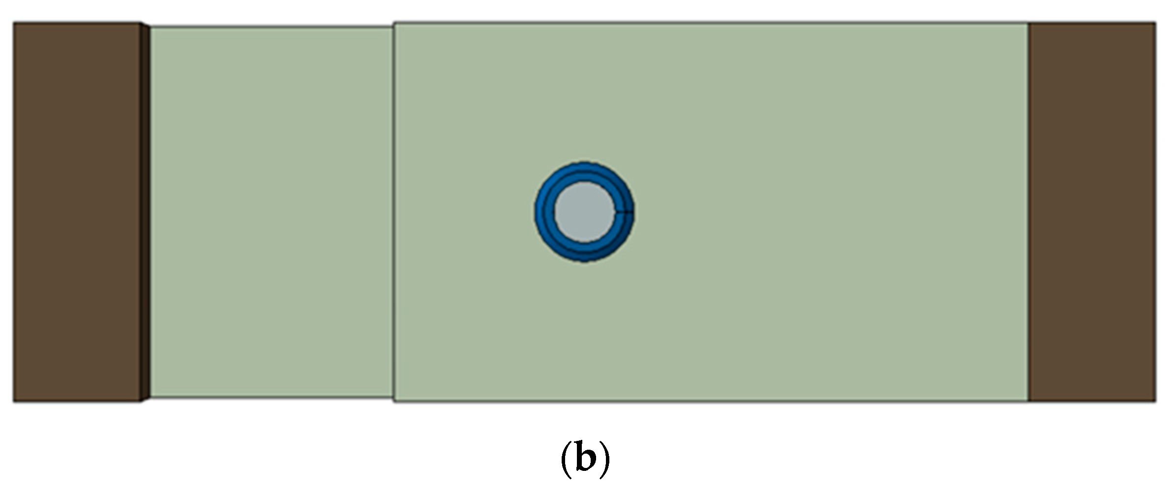
The schematic diagram of the laminate in the bolted joint structure is shown in Figure 2. The single-lap and double-lap laminate bolted joints are investigated in this paper. A double-lap single bolt joint (DSJ) model and a single-lap single bolt joint (SSJ) model are constructed, respectively, as shown in Figure 3 and Figure 4.
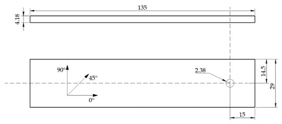
Figure 2.
Laminate size schematic diagram.
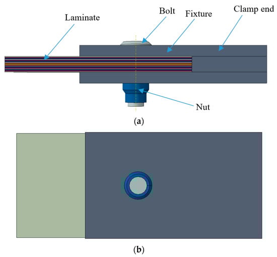
Figure 3.
Double-lap bolted laminate joint schematic diagram; (a) front view; (b) top view.

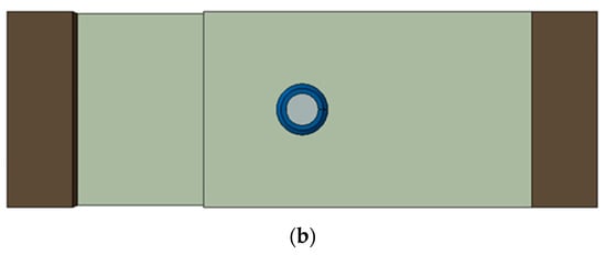
Figure 4.
Single-lap bolted laminate joint schematic diagram; (a) front view; (b) top view.
In order to meet the analytical accuracy, a three-dimensional body element is used to compute the stress through the laminate, which significantly influences the failure process. The contact between the laminate and the bolt was taken into consideration.
In the analysis process, we need to consider the contact between the bolt and the composite plate, and the adjacent layers of the composite plate, and use General contact in ABAQUS to simulate these contacts. Considering the normal and tangential interaction of the contact surface, “Hard” Contact is used to simulate the normal contact between the bolt and the composite plate and the adjacent layers of the composite plate; Penalty is used to define the tangential interaction between the bolt and the composite plate and the adjacent layers of the composite plate.
The boundary condition is reproduced according to the standard experimental method. The rotational degrees of freedom in all directions of the nodes at one end of the model are set to zero. Only one direction of displacement at the other end of the model is set according to the standard test, and the other two directions of displacement are set to zero. The displacement loads of the SSJ and DSJ models are applied along the x direction only.
The main concerning point of this model analysis is the failure processes of laminates, so a tie constraint is set between the bolt and nut, which means there is no displacement between them and the damage to them is ignored. On the other hand, the interface between single-layer plates was simulated by a cohesive model. Additionally, the contact between the fastener and composite plates and the contact between composite plates are defined using general contact embodied in ABAQUS. The material properties are shown in Table 2.
Table 2.
Materials properties of laminate [14,19].
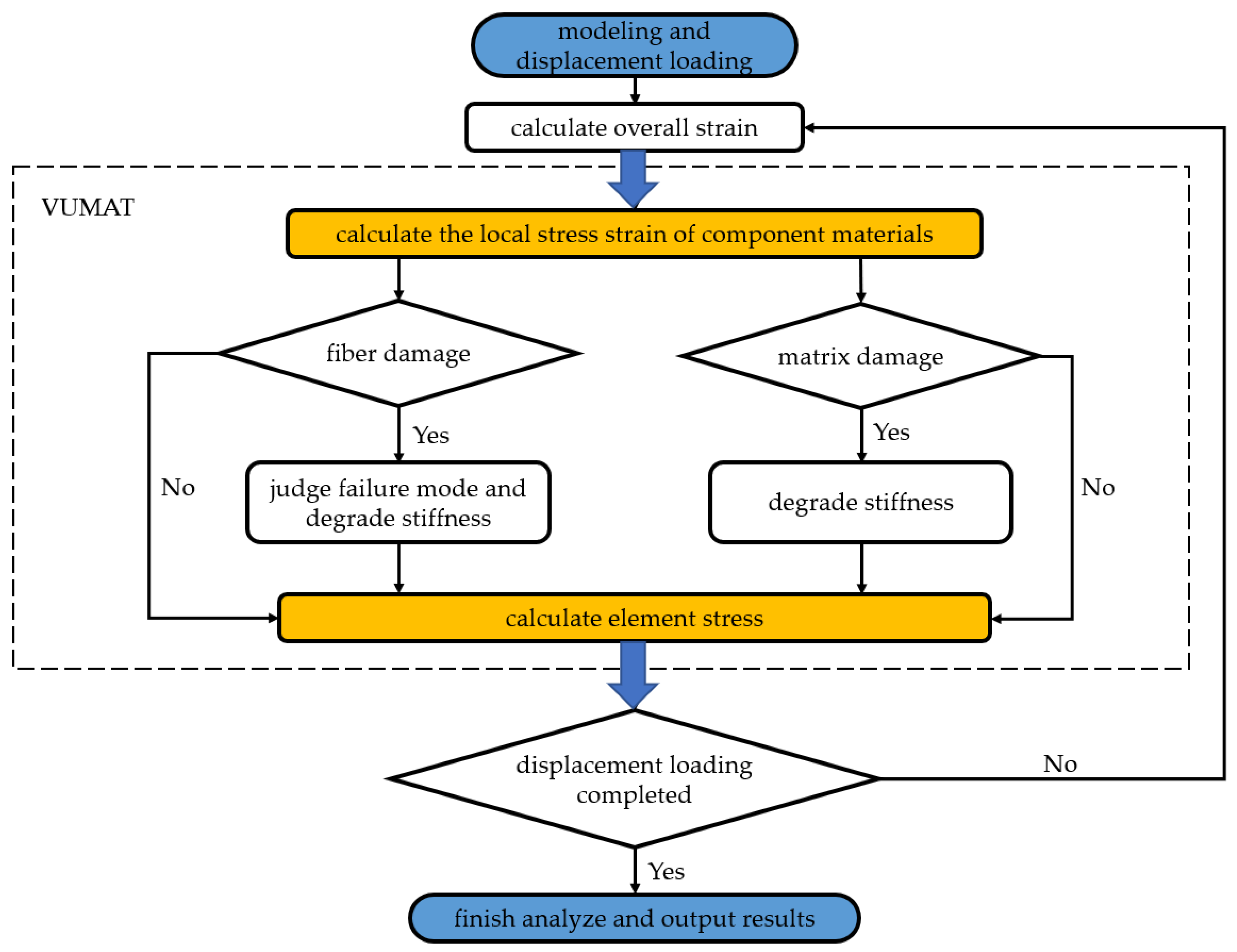
The initial damage model and progressive degradation model are implemented into a user-defined material subroutine VUMAT in ABAQUS. The calculation method and the process of the program are shown in Figure 5.
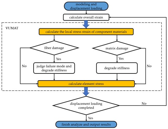
Figure 5.
Calculation method and process.
5. Result and Discussion
To verify the reliability of the model developed in this paper, both single-lap and double-lap bolted joint composite materials are experimentally investigated according to ASTM D5961. The experimental data are recorded and results are analyzed.
5.1. DSJ Model
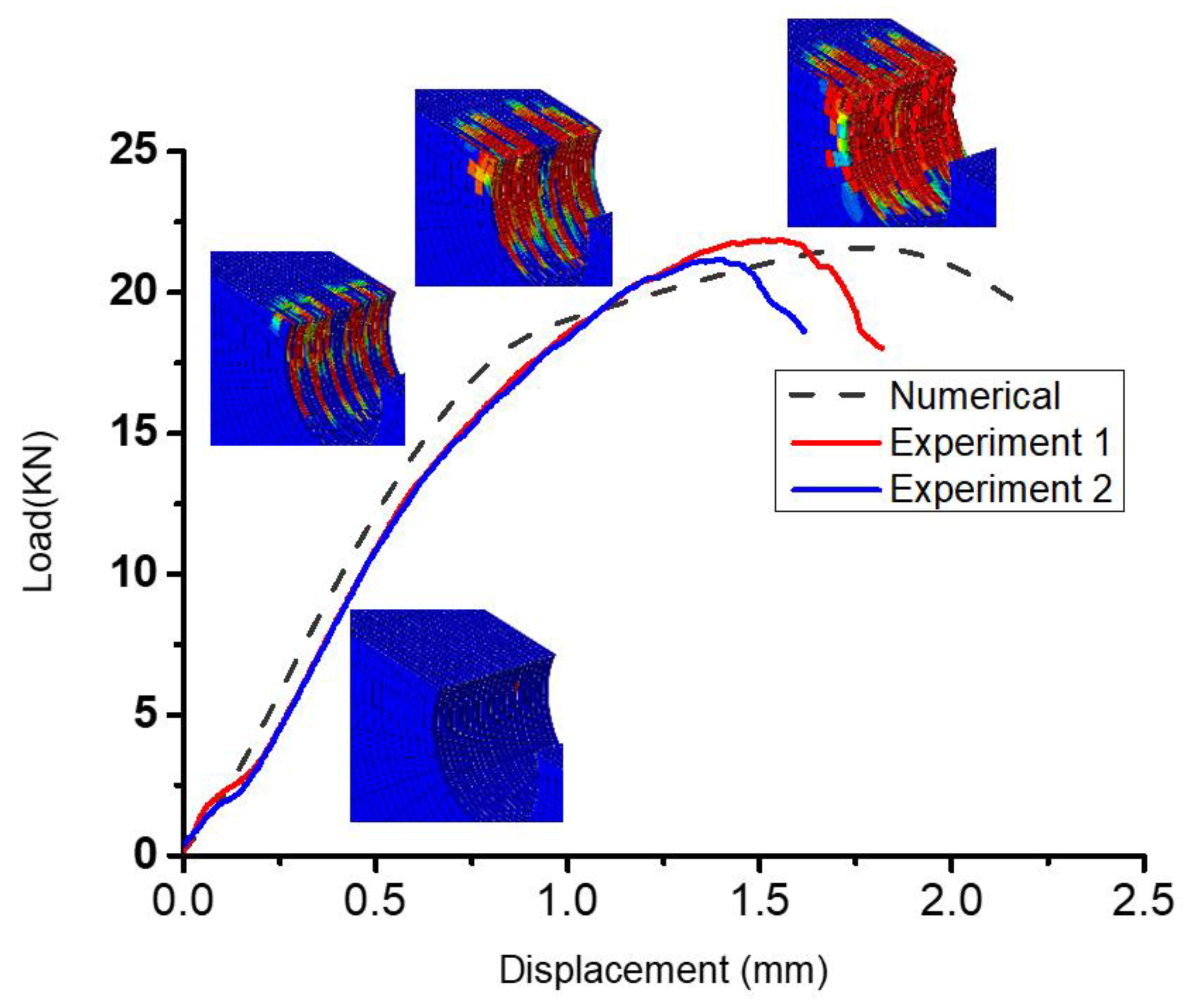
A comparison between the experimental and numerical load-displacement curves of the DSJ model is shown in Figure 6, which shows that the calculation curve is in good agreement with the experimental curves. The mean value of the tested bearing force is 21.30 kN and of the numerical simulation results, it is 21.93 kN. The standard deviation is 6.30%. It can be concluded that the progressive damage model established in this paper can well describe the failure behavior of double-lap composite laminate bolted joints.
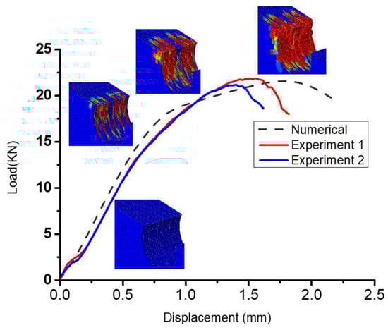
Figure 6.
Load versus displacement curve of a double-lap bolted joint under tension (experimental and numerical).
Resulting from the assembly gap between the composite plate and the fasteners, the initial stage of the load displacement curve shows a certain bending fluctuation. Then, the two gradually coincide and the load starts to grow steadily. When the load reaches a certain critical value, the slope of the curve begins to decline, at which time the failure criterion determines that the initial damage to the material occurs, and the overall performance of the material begins to decline. When the slope of the curve gradually decreases to zero, the load reaches the ultimate bearing capacity of the structure. When a few units are damaged, the overall performance of the structure is not affected much. The gradual accumulation of damaged units will eventually lead to a change in the entire structural mechanical performance, the most important change is the integral stiffness of the structure. Throughout the loading process, the damage to a single element gradually accumulates and eventually causes the overall failure of the structure.
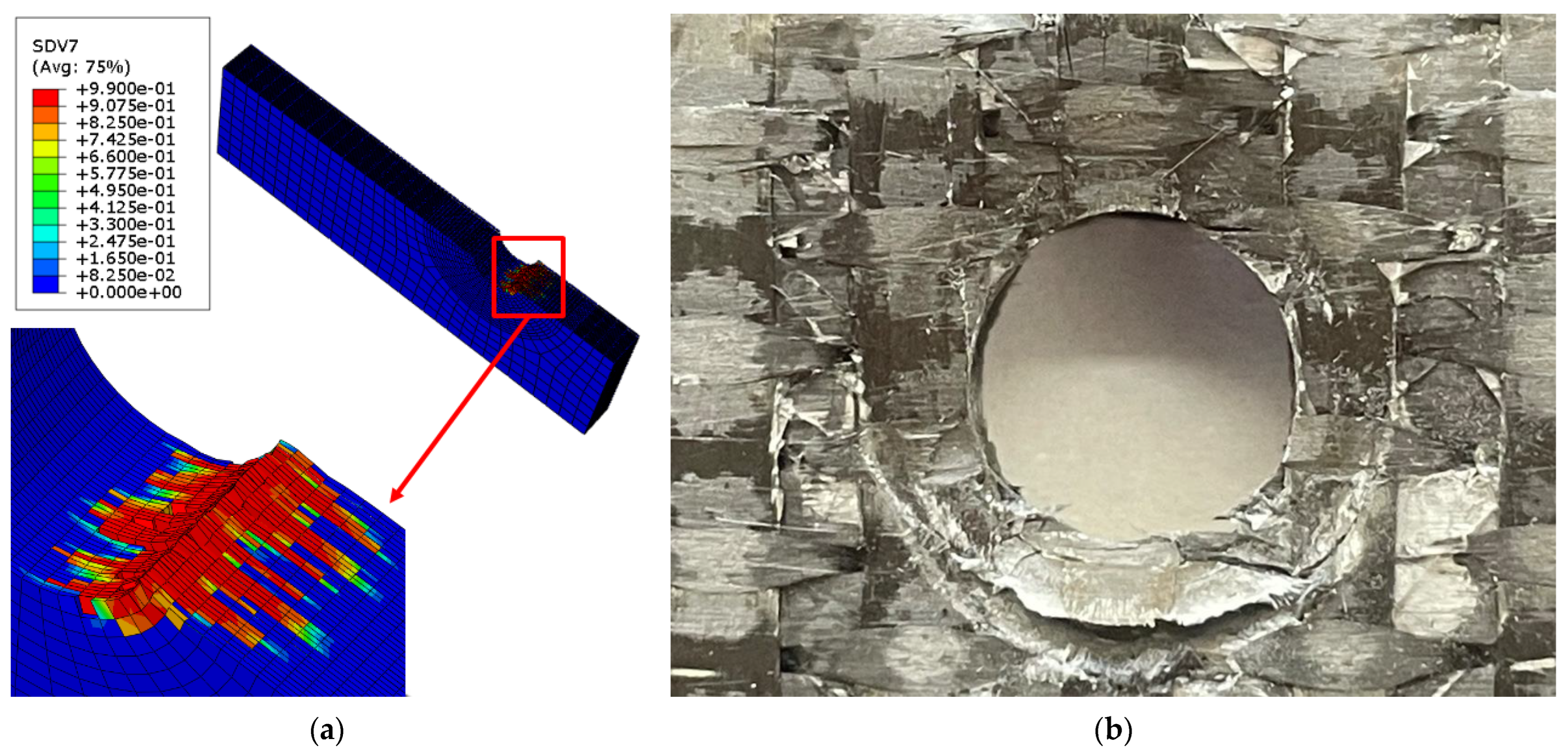
As shown in Figure 7, the damage modes of the finite element model and the experiment sample are in good agreement, and when the structure finally fails, damage and failure occur in a large number of units around the hole. As the laminated plates are made of different layers in the direction of stacked layers, material damage is associated with the layer order. The failure of the main bearing layer is especially serious, so a reasonable layered design has very important significance to improve the overall performance of the structure.

Figure 7.
Eventual damage and failure diagram (double-lap joint); (a) FEM; (b) experiment sample.
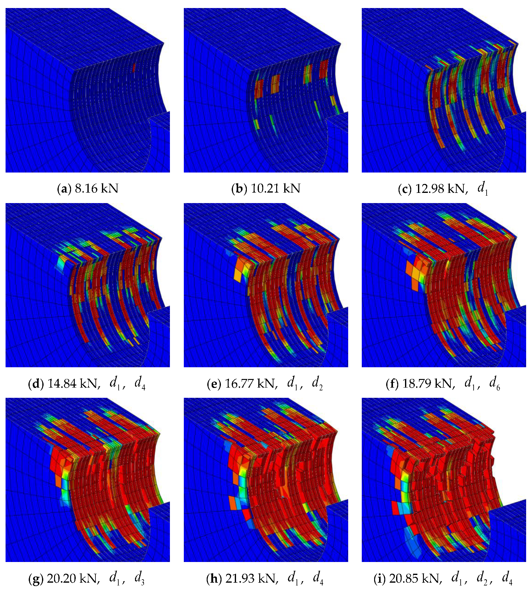
Figure 8 represents the damage of the element around the hole during the loading process of the double-lap bolt joint structure. In the process, the stress distribution at the hole is relatively uniform, and the loading direction is perpendicular to the surface of the composite plate. After the stage of initial damage, under zero-degree directional loading, the first damage occurs on the zero-degree layer. As the damage gradually accumulates, the zero-degree layer is damaged and the bearing capacity decreases, at which time the stresses are redistributed and the remaining layers also burden the load. The material eventually fails due to extensively damaged elements appearing on the contact zone. The damage occurs mainly on the side with the larger hole load. The damage associated with d1 appeared at the beginning of the initial stage of the damage (Figure 8c), and as the load grew, damage associated with d2, d3, d4 and d6 gradually appeared, but the process was always dominated by the damage associated with d1. The ultimate failure modes are fiber bundle compression failure associated with d1 and fiber bundle shear failure associated with d4 and d6.
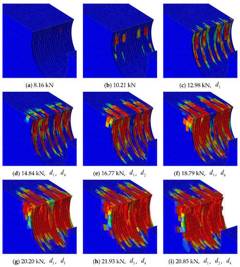
Figure 8.
Damage evolution around the hole (double-lap joint).
5.2. SSJ Model
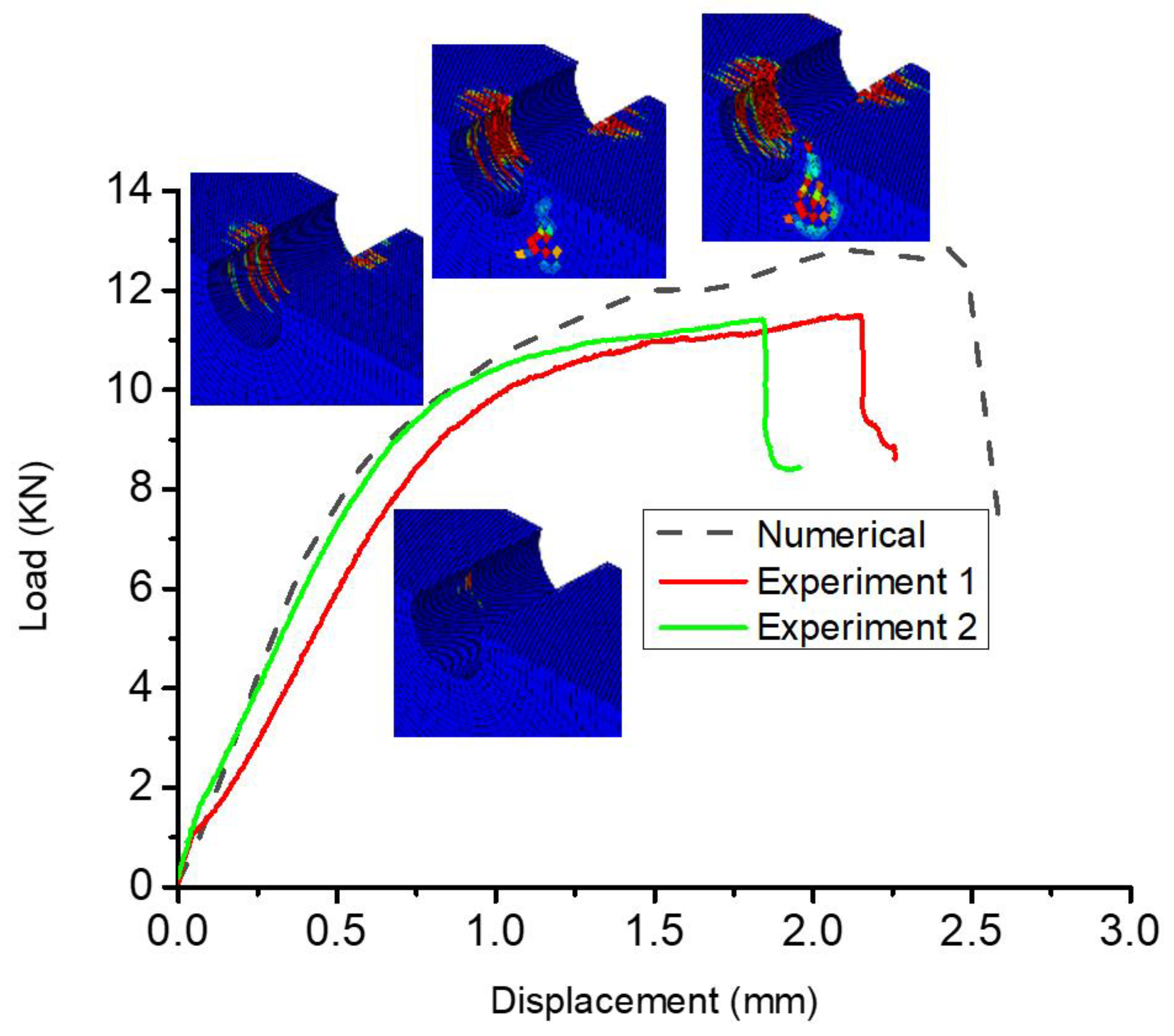
A comparison between the experimental and numerical load-displacement curves of the SSJ model is shown in Figure 9, which shows that the calculation curve is in good agreement with the experimental curves. The mean value of the tested bearing force is 11.15 kN and of the numerical simulation results, it is 11.89 kN. The standard deviation is 6.64%. It can be concluded that the progressive damage model established in this paper can well describe the failure behavior of single-lap composite laminate bolted joints. The eventual damage and failure diagram is shown in Figure 10, and it can be seen that the damage modes of the FEM of the single-lap bolt joint structure and the experiment sample are basically the same.

Figure 9.
Load versus displacement curve of a single-lap bolted joint under tension (experimental and numerical).
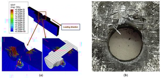
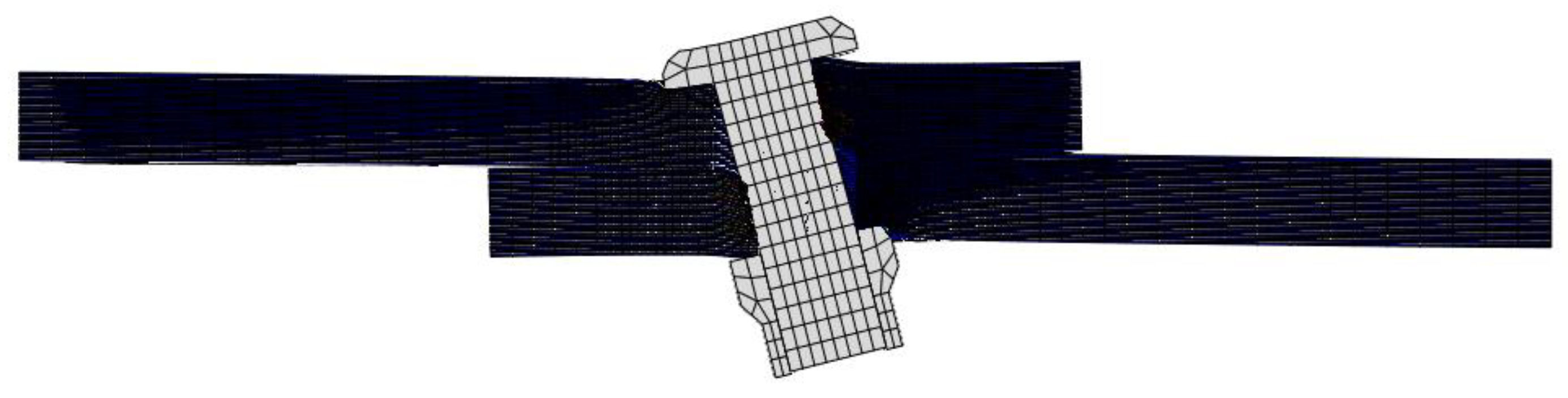
Figure 10.
Eventually damage and failure diagram (single-lap joint); (a) FEM; (b) experiment sample.
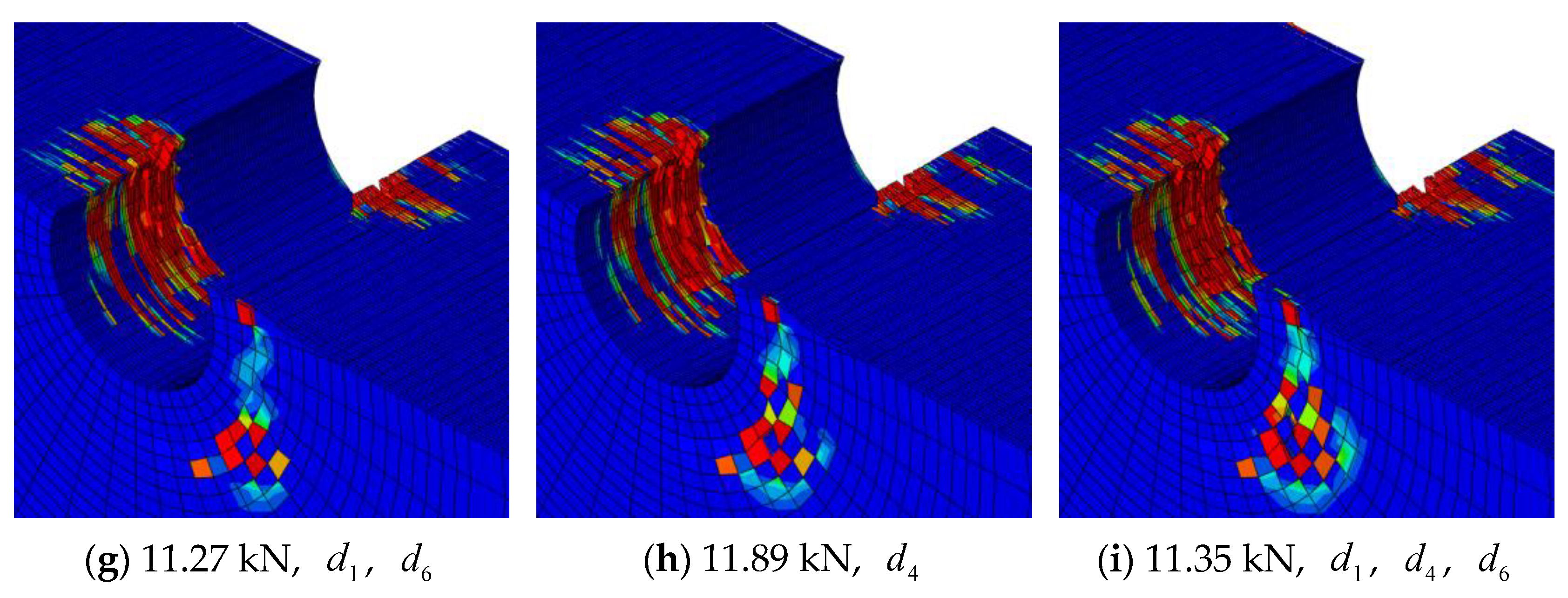
The damage and failure processes of single-lap and double-lap bolted joints are quite different. In the loading process of a single-lap joint structure, the contact with the hole side is incomplete contact due to the rotational displacement of the bolt. When the material contact surface is not perpendicular to the loading direction, the composite plates on both sides of the hole cannot be loaded at the same time. As the damage accumulates, the stresses are redistributed and the structure can continue to carry the load. Since the material is extruded, the composite material near the bolts gradually fails from near to far, resulting in a significant increase in material plasticity. The maximum bearing capacity of the single-lap bolted structure is reduced compared to the double-lap joint. It can be seen that relatively non-uniform load distribution can improve the structural plasticity compared with the double-lap bolt joint structure, but at the same time, it also reduces the ultimate bearing capacity of the structure. Thus, single-lap and double-lap joints represent two typical modes of extrusion failure in bolted structures. In actual bolted joint structure failure, most cases are a mixture of two kinds of bolted joints. Damage evolution around the hole of a single-lap joint is exhibited in Figure 11. Therefore, a reasonable design of the ratio of the two connection forms can obtain better plasticity and better structural strength. The damage associated with d1 appeared at the beginning of the initial stage of the damage (Figure 8c), and as the load grow, damage associated with d2, d3, d4 and d6 gradually appeared, but the process is always dominated by the damage associated with d1. The ultimate failure modes are fiber bundle compression failure associated with d1 and fiber bundle shear failure associated with d4 and d6.
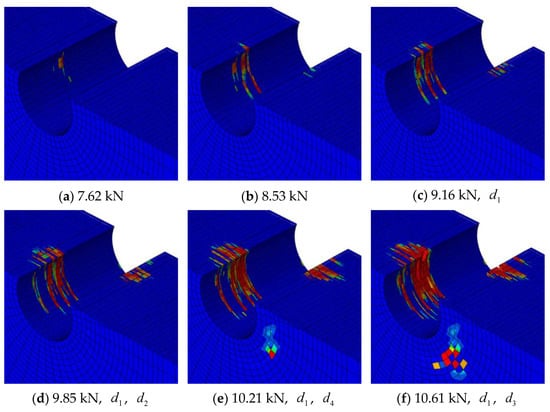
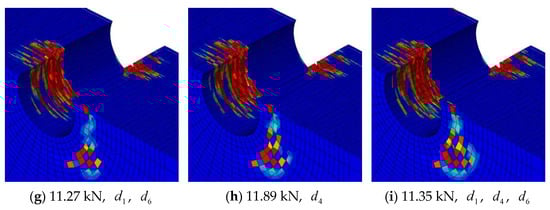
Figure 11.
Damage evolution around the hole (single-lap joint).
On the other hand, secondary deflection of the bolt will cause extrusion failure on the surface of the composite laminated plate in the process of loading. Therefore, appropriately increasing the contact area of the nut and the surface of the composite laminate, or adding a gasket, can reduce the stress concentration to a certain extent, thus further improving the ultimate bearing capacity of bolted joint structure, while keeping the good characteristics of plasticity. Figure 12 gives the diagram of a secondary bending effect in the single-lap bolted joint.
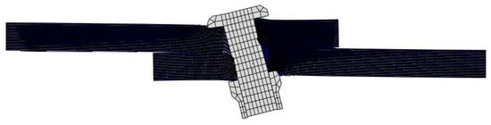
Figure 12.
The secondary bending effect in the single-lap bolted joint.
In summary, as the load increases, damage starts from one side of the composite laminated plate, then gradually expands to the other side. When the composite laminated bolted joint finally fails, the other side of the laminated plates has almost no damage and the performance of the material is not fully played out, which also leads to the ultimate bearing capacity of the single-lap bolt connection structure being lower than that of the double-lap bolted joint.
6. Conclusions
A set of three-dimensional detailed finite element progressive damage modeling methods is proposed to predict the failure behavior of the composite laminated bolted joint structure. In addition, the experimental study of single-lap and double-lap bolted structures under tensile load is carried out, and the experimental data are compared with the model prediction results to verify the reliability of the proposed model. Some valuable conclusions can be drawn as follows.
- The proposed model can effectively predict the progressive damage and failure behavior of composite single-lap and double-lap bolted structures.
- For double-lap bolted joints, as the load increases, the damage that first appears in the zero-degree layer gradually extends to the other layers due to stress redistribution, and eventually the material fails. The damage of the main bearing layer at failure is obviously more serious than the other layers, so the reasonable design of composite laminate lay-up can improve the structural mechanical properties.
- During the failure process of a single-lap bolted joint, the bolts rotate, resulting in non-uniform stresses on both surfaces of the composite plate. The structure can continue to carry loads after the accumulation of damage leads to stress redistribution. Eventually, damage occurs near the hole from near to far because of extrusion. For the single-lap joint bolt connection, the secondary deflection of the bolt has a great influence on the failure process of the structure.
- The double-lap bolt lap structure has better ultimate strength than the single-lap joint structure, and the single-lap joint structure has better performance of plastic.
Author Contributions
Conceptualization, G.L. and F.L.; methodology, F.L. and C.L.; software, C.L. and S.Z.; validation, G.L. and W.L.; formal analysis, C.L.; investigation, Y.Z.; resources, W.L.; writing—original draft preparation, C.L.; writing—review and editing, G.L. and W.L.; supervision, W.L.; project administration, G.L.; funding acquisition, G.L. and S.Z. All authors have read and agreed to the published version of the manuscript.
Funding
This research was funded by the Jiangxi Provincial Natural Science Foundation (Grant No. 20212BAB211007 and Grant No. 20202BAB211005), Department of Education of Jiangxi Province (Grant No. GJJ190328).
Institutional Review Board Statement
Not applicable.
Informed Consent Statement
Not applicable.
Data Availability Statement
Not applicable.
Acknowledgments
We thank Licheng Guo’s group in the Department of Aerospace Science and Mechanics of Harbin Institute of Technology for the simulation guidance. Thanks for the help from DE.testing (JIANGSU) Co., Ltd. in the experiment, as well.
Conflicts of Interest
The authors declare that they have no known competing financial interests or personal relationships that could have appeared to influence the work reported in this paper.
References
- Rajak, D.K.; Pagar, D.D.; Kumar, R.; Pruncu, C.I. Recent progress of reinforcement materials: A comprehensive overview of composite materials. J. Mater. Res. Technol. 2019, 8, 6354–6374. [Google Scholar]
- Wang, X.; Guan, Z.; Liu, N.; Zhang, M.; Li, Z.; Meng, Q.; Du, S. A 3D micromechanics-based failure criterion for fiber reinforced composites under longitudinal compression. Compos. Part A-Appl. Sci. Manuf. 2022, 161, 107076. [Google Scholar]
- Khalid, M.Y.; Rashid, A.A.; Arif, Z.U.; Akram, N.; Arshad, H.; Marquez, F.P.G. Characterization of failure strain in fiber reinforced composites: Under on-axis and off-axis loading. Crystals 2021, 11, 216. [Google Scholar]
- Liu, Y.; Zhang, L.; Li, Z.; Chen, Z.; Huang, K.; Guo, L. Investigation on damage evolution of open-hole plain woven composites under tensile load by acoustic emission signal analysis. Compos. Struct. 2023, 305, 116481. [Google Scholar]
- Hung, C.L.; Chang, F.K. Bearing failure of bolted composite joints. Part II: Model and verification. J. Compos. Mater. 1996, 30, 1359–1400. [Google Scholar]
- Vadean, A.; Leray, D.; Guillot, J. Bolted joints for very large bearings—Numerical model development. Finite Elem. Anal. Des. 2006, 42, 298–313. [Google Scholar]
- Veisi, H.; Kordkheili, S.A.H.; Toozandehjani, H. Progressive bearing failure modeling of composites with double-bolted joints at mesoscale level. Arch. Appl. Mech. 2014, 84, 657–669. [Google Scholar] [CrossRef]
- Liu, F.R.; Lu, X.H.; Zhao, L.; Zhang, J.; Hu, N.; Xu, J. An interpretation of the load distributions in highly torqued single-lap composite bolted joints with bolt-hole clearances. Compos. Part B Eng. 2018, 138, 194–205. [Google Scholar]
- Liu, H.; Sun, W.; Du, D.; Liu, X. Modeling and free vibration analysis for bolted composite plate under inconsistent pre-tightening condition. Compos. Struct. 2022, 292, 115634. [Google Scholar]
- Chang, F.K.; Chang, K.Y. Post-failure analysis of bolted composite joints in tension or shear-out mode failure. J. Compos. Mater. 1987, 21, 809–833. [Google Scholar] [CrossRef]
- Ekh, J.; Schön, J. Effect of secondary bending on strength prediction of composite, single shear lap joints. Compos. Sci. Technol. 2005, 65, 953–965. [Google Scholar]
- Montagne, B.; Lachaud, F.; Paroissien, E.; Martini, D.; Congourdeau, F. Failure analysis of single lap composite laminate bolted joints: Comparison of experimental and numerical tests. Compos. Struct. 2020, 238, 111949. [Google Scholar] [CrossRef]
- Catalanotti, G.; Camanho, P.P.; Ghys, P.; Marques, A.T. Experimental and numerical study of fastener pull-through failure in GFRP laminates. Compos. Struct. 2011, 94, 239–245. [Google Scholar]
- Li, X.; Li, Y.; Li, F.; Huang, Z.; Chen, H. Failure analysis and experimental study on bolted composite joints based on continuum damage mechanics. Compos Struct. 2023, 303, 116274. [Google Scholar]
- Qin, T.; Zhao, L.; Zhang, J. Fastener effects on mechanical behaviors of double-lap composite joints. Compos. Struct. 2013, 100, 413–423. [Google Scholar] [CrossRef]
- Gray, P.J.; O’Higgins, R.M.; McCarthy, C.T. Effect of thickness and laminate taper on the stiffness, strength and secondary bending of single-lap, single-bolt countersunk composite joints. Compos. Struct. 2014, 107, 315–324. [Google Scholar]
- Xiao, Y.; Ishikawa, T. Bearing strength and failure behavior of bolted composite joints (part II: Modeling and simulation). Compos. Sci. Technol. 2005, 65, 1032–1043. [Google Scholar]
- Xiao, Y.; Ishikawa, T. Bearing strength and failure behavior of bolted composite joints (part I: Experimental investigation). Compos. Sci. Technol. 2005, 65, 1022–1031. [Google Scholar]
- Dano, M.-L.; Kamal, E.; Gendron, G. Analysis of bolted joints in composite laminates: Strains and bearing stiffness predictions. Compos. Struct. 2007, 79, 562–570. [Google Scholar]
- Ireman, T. Three-dimensional stress analysis of bolted single-lap composite joints. Compos. Struct. 1998, 43, 195–216. [Google Scholar] [CrossRef]
- Wang, J.; Qin, T.; Mekala, N.R.; Li, Y.; Heidari-Rarani, M.; Schroeder, K.W. Three-dimensional progressive damage and failure analysis of double-lap composite bolted joints under quasi-static tensile loading. Compos. Struct. 2022, 285, 115227. [Google Scholar]
- Ahmad, H.; Crocombe, A.D.; Smith, P.A. Strength prediction in CFRP woven laminate bolted double-lap joints under quasi-static loading using XFEM. Compos. Part A Appl. Sci. Manuf. 2014, 56, 192–202. [Google Scholar]
- Stocchi, C.; Robinson, P.; Pinho, S.T. A detailed finite element investigation of composite bolted joints with countersunk fasteners. Compos. Part A Appl. Sci. Manuf. 2013, 52, 143–150. [Google Scholar] [CrossRef]
- Egan, B.; McCarthy, M.A.; Frizzell, R.M.; Gray, P.J.; McCarthy, C.T. Modelling bearing failure in countersunk composite joints under quasi-static loading using 3D explicit finite element analysis. Compos. Struct. 2014, 108, 963–977. [Google Scholar] [CrossRef]
- Mehmood, S.; Zhao, L.; Hai, H. Failure analysis of single and double bolted joints for composite laminates. In Proceedings of the IEEE 2015 12th International Bhurban Conference on Applied Sciences and Technology, Islamabad, Pakistan, 13–17 January 2015. [Google Scholar]
- Mehrmashhadi, J.; Bahadori, M.; Bobaru, F. On validating peridynamic models and a phase-field model for dynamic brittle fracture in glass. Eng. Fract. Mech. 2020, 240, 107355. [Google Scholar]
- Liu, F.; Yao, W.; Zhao, L.; Wu, H.; Zhang, X.; Zhang, J. An improved 2d finite element model for bolt load distribution analysis of composite multi-bolt single-lap joints. Compos. Struct. 2020, 253, 112770. [Google Scholar]
- Zhong, S.; Guo, L.; Liu, G.; Lu, H.; Zeng, T. A continuum damage model for three-dimensional woven composites and finite element implementation. Compos. Struct. 2015, 128, 1–9. [Google Scholar]
- Liu, G.; Zhang, L.; Guo, L.; Liao, F.; Zheng, T.; Zhong, S. Multi-scale progressive failure simulation of 3D woven composites under uniaxial tension. Compos. Struct. 2019, 208, 233–243. [Google Scholar]
- Puck, A.; Schürmann, H. Failure analysis of FRP laminates by means of physically based phenomenological models. Compos. Sci. Technol. 2004, 62, 1633–1662. [Google Scholar]
- Zheng, T.; Guo, L.; Benedictus, R.; Pascoe, J. Micromechanics-based multiscale progressive failure simulation of 3D woven composites under compressive loading with minimal material parameters. Compos. Sci. Technol. 2022, 219, 109227. [Google Scholar] [CrossRef]


Disclaimer/Publisher’s Note: The statements, opinions and data contained in all publications are solely those of the individual author(s) and contributor(s) and not of MDPI and/or the editor(s). MDPI and/or the editor(s) disclaim responsibility for any injury to people or property resulting from any ideas, methods, instructions or products referred to in the content. |
© 2023 by the authors. Licensee MDPI, Basel, Switzerland. This article is an open access article distributed under the terms and conditions of the Creative Commons Attribution (CC BY) license (https://creativecommons.org/licenses/by/4.0/).