Abstract
We analyze the effect of growth on non-(100) surfaces resulting from incomplete planarization of spalled GaAs wafers on the defect structure of GaAs solar cell layers grown by hydride vapor phase epitaxy (HVPE). Controlled spalling of (100)-oriented GaAs has the potential to reduce substrate costs for III-V epitaxy; however, it creates regularly faceted surfaces that may complicate the growth of high-quality III-V optoelectronic devices. We leverage the anisotropic growth rate of HVPE to planarize these faceted GaAs substrates, reducing the surface roughness and degree of faceting. We observe degraded solar cell performance and material quality in sample areas where facets are not completely removed. We used dark lock-in thermography and photoluminescence to identify recombination in areas that were not fully planarized. We used cathodoluminescence to identify the presence of extended defects in these regions, which are correlated with bandgap fluctuations in the material. We hypothesize that these defects were created by strain from compositional fluctuations in ternary alloys grown on the faceted surfaces. This work elucidates the potential issues of solar cells grown on faceted surfaces and builds understanding toward realizing high performance III-V photovoltaics with the cost-reduction potential of controlled spalling.
1. Introduction
III-V devices employ high-quality epitaxial thin films typically deposited on atomically smooth, polished, ~(100)-oriented substrates. For large area devices, especially photovoltaics, a single use of these polished substrates contributes substantially to the device cost. Reusing a single substrate 10 times or more with minimal repreparation stands to reduce substrate costs by over 50% [1,2]. Cost reductions in materials’ growth may be possible by leveraging the high throughput potential of HVPE growth [1,3,4,5], thereby benefitting existing III-V markets, such as space PV, micro-LEDs, and photonics, and potentially enabling the entrance of III-V materials into other markets, such as terrestrial PV. Substrate reuse also confers technical advantages to III-V PV by removing the active device from the substrate, which is far thicker than necessary due to the high absorption coefficients of III-V materials [6]. This allows the use of back reflectors, which can enhance photovoltaic performance [7], leading to higher efficiency and enabling better radiation tolerance [8]. Additionally, the reduced thickness and mass enable flexible cells with high specific power, which are highly desirable traits for aerospace applications.
The current industrial standard for substrate reuse, epitaxial lift-off (ELO), has achieved some degree of substrate reuse, but further cost reduction is limited by low throughput of the lateral etching step and the periodic need for repolishing [2,9]. Alternative strategies for device lift-off and subsequent substrate reuse include controlled spalling [10], laser lift-off [11], multiple ELO [12], porous substrates [13,14,15,16,17], and remote epitaxy [18]. Controlled spalling is a promising substrate reuse technique with the potential to exfoliate devices at high throughput, leaving behind a chemically pure fracture surface for regrowth [10,19,20]. The spalling fracture for (100)-oriented GaAs substrates produces a regularly corrugated surface of >5 µm peak-to-trough height facets [21,22]. Recent advances in spalling techniques have enabled predominantly smooth surfaces; however, faceted regions can still remain and are largely unavoidable without fracture-guiding layers due to the orientation of favorable fracture planes [23,24]. Ideally, the fracture surfaces can be grown on directly without the added cost related to external planarization, e.g., chemo-mechanical polishing. However, the faceted surface presents a challenge for the direct use of spalled substrates for the growth of high-efficiency III-V solar cells, which have traditionally employed flat epilayers. Other work has investigated solar cells on non-pristine growth surfaces [9,15,16,25,26,27,28], and has observed that some morphological spalling defects diminish cell performance [29,30]. However, the impact, if any, of these particular faceted GaAs surfaces on the quality of subsequently grown materials and devices is unexplored.
In this work, we utilized planarizing GaAs buffer layers described in a prior work [31] to smooth the faceted surfaces of spalled GaAs substrates. Then we grew solar cells with planarizing buffer layers just thick enough to planarize the predominant facet size. However, some regions on the wafer showed incomplete planarization after the growth, resulting in localized areas where facet troughs were still visible. We evaluated solar cell devices containing these regions of incomplete planarization to assess the impact of these residual facets on device performance and determine whether complete planarization is necessary as part of a potential process flow that includes spalling. We used a variety of device- and micro-scale characterization techniques to locate and analyze the impact of incomplete planarization on material quality and device performance and correlated this with the post-growth surface morphology.
2. Experimental Section
Faceted substrates were produced by controlled spalling of n-type, (100)-oriented GaAs wafers with a 6° offcut toward (111)A using an electroplated nickel stressor layer. The nickel stressor layer was deposited on full 2″ wafers using a 2-electrode electroplating system in current-controlled mode (galvanostatic), following procedures described in [21,32]. This system used a Ni metal electrode in a Ni-P bath with 0.6 M NiCl2 × 6H2O and 5 mM H3PO3. Wafers were then spalled in the [01] direction (perpendicular to the 6°A offcut) to yield a faceted surface consisting of nominally {n11}B planes with roughly 6 µm peak-to-trough height [23].
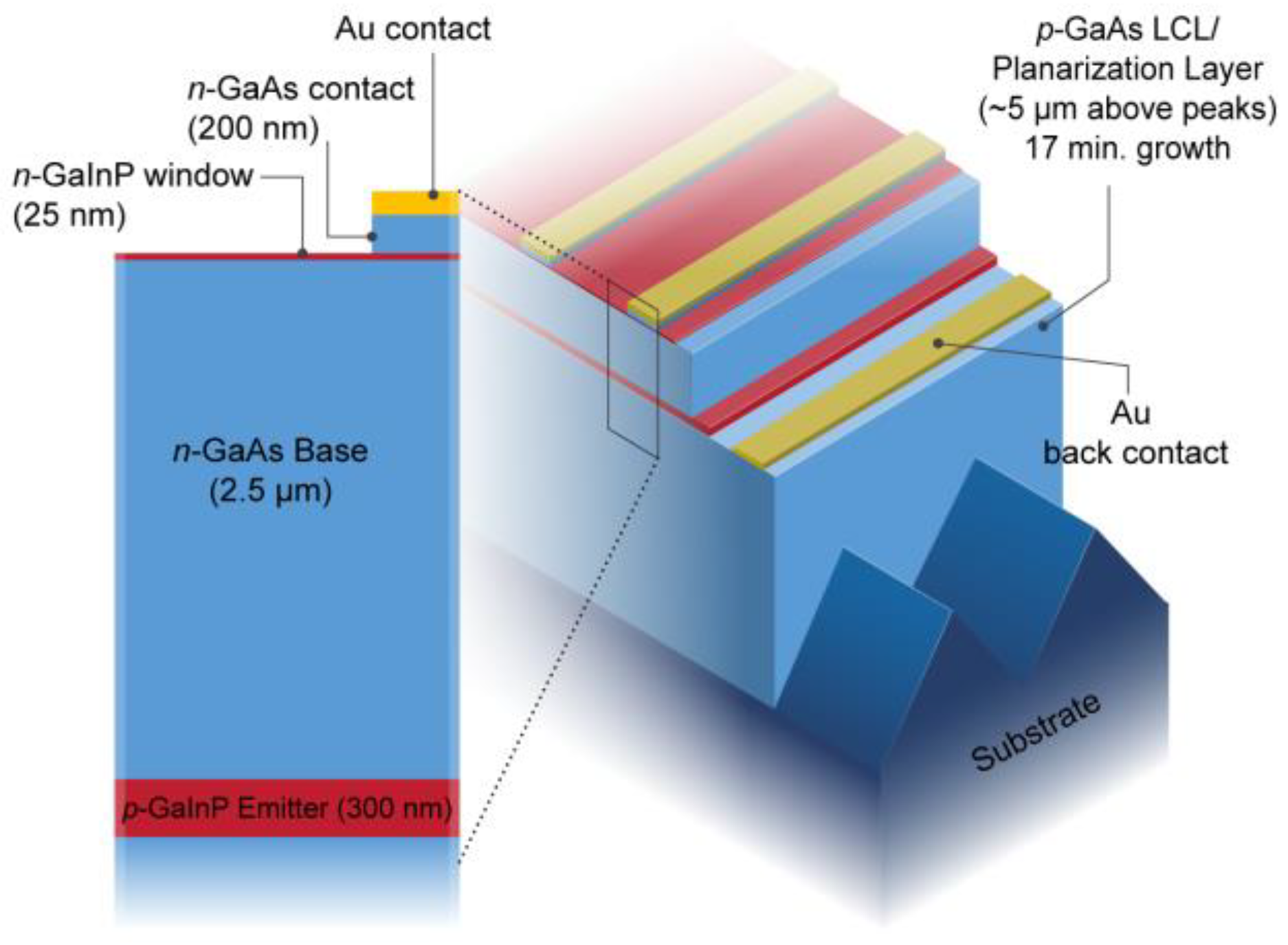
A custom-built, two-growth-chamber dynamic HVPE reactor, described elsewhere [33], was used for all growths. Upright, rear heterojunction GaAs solar cells were grown on both spalled (faceted) and polished epi-ready substrates using conditions and structures similar to those reported in [34]. The 2.5 µm n-GaAs base layer was doped with Se to 1.5 × 1017 cm−3 and the p-GaInP emitter was doped to ~3 × 1019 cm−3 with Zn. A ~25 nm GaInP:Se window layer provided front surface passivation, and a heavily Se-doped GaAs layer served as the front contact layer. The same cell structure was grown on the two substrates: spalled with facets and a traditional, planar epi-ready substrate. Both substrates were cleaved into ~2 cm × 2 cm pieces and then cleaned with a one minute 2:1:10 NH4OH:H2O2:H2O etch to remove cleaving debris. The overall structure is depicted in Figure 1 on the spalled substrate. The planarization layer was grown using 15 sccm of GaCl and 50 sccm of AsH3, as reported in [31], to fill the trenches and resulted in approximately 5 µm of material measured from the tops of the facet peaks. The planarization layer also acted as a lateral conduction layer (LCL) for back contact of the cell. The control devices on the epi-ready substrate were grown with a nominally 5 µm thick LCL to mimic the test structure. Both LCL layers were Zn-doped to ~1 × 1018 cm−3.
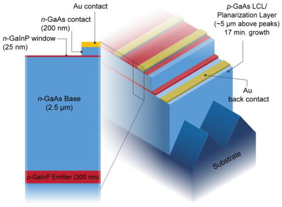
Figure 1.
Structure of an upright rear heterojunction GaAs solar cell on a planarized spalled GaAs wafer. The facets and cell structure are drawn to scale. Devices on epi-ready GaAs use the same solar cell structure with a ~5 μm thick GaAs LCL grown prior to the cell stack.
Samples were processed into 0.25 cm2 photovoltaic devices using standard lithography techniques. Laser confocal optical profilometry was conducted on these samples before and after growth to measure the surface morphology. Dark lock-in thermography (DLIT) was conducted on select devices under forward and reverse bias conditions. Photoluminescence (PL) maps were acquired on select devices that were pumped by a 532 nm light source. Cross-sectional SEM micrographs were acquired from select samples. Electron channeling contrast imaging (ECCI) was conducted on these cross-sections using methods reported in [35]. Cathodoluminescence (CL) and electron-beam-induced current (EBIC) measurements were performed on a JEOL JSM 7600 field emission scanning electron microscope (FESEM) operated with an accelerating voltage of 5 kV and beam current of 0.4 nA and 1.4 nA for CL and EBIC analyses, respectively. CL spectrum per pixel mapping data was acquired using a Horiba H-CLUE system equipped with a Si CCD array. Quantitative EBIC images were acquired with a Mighty EBIC system from Ephemeron Labs.
3. Results
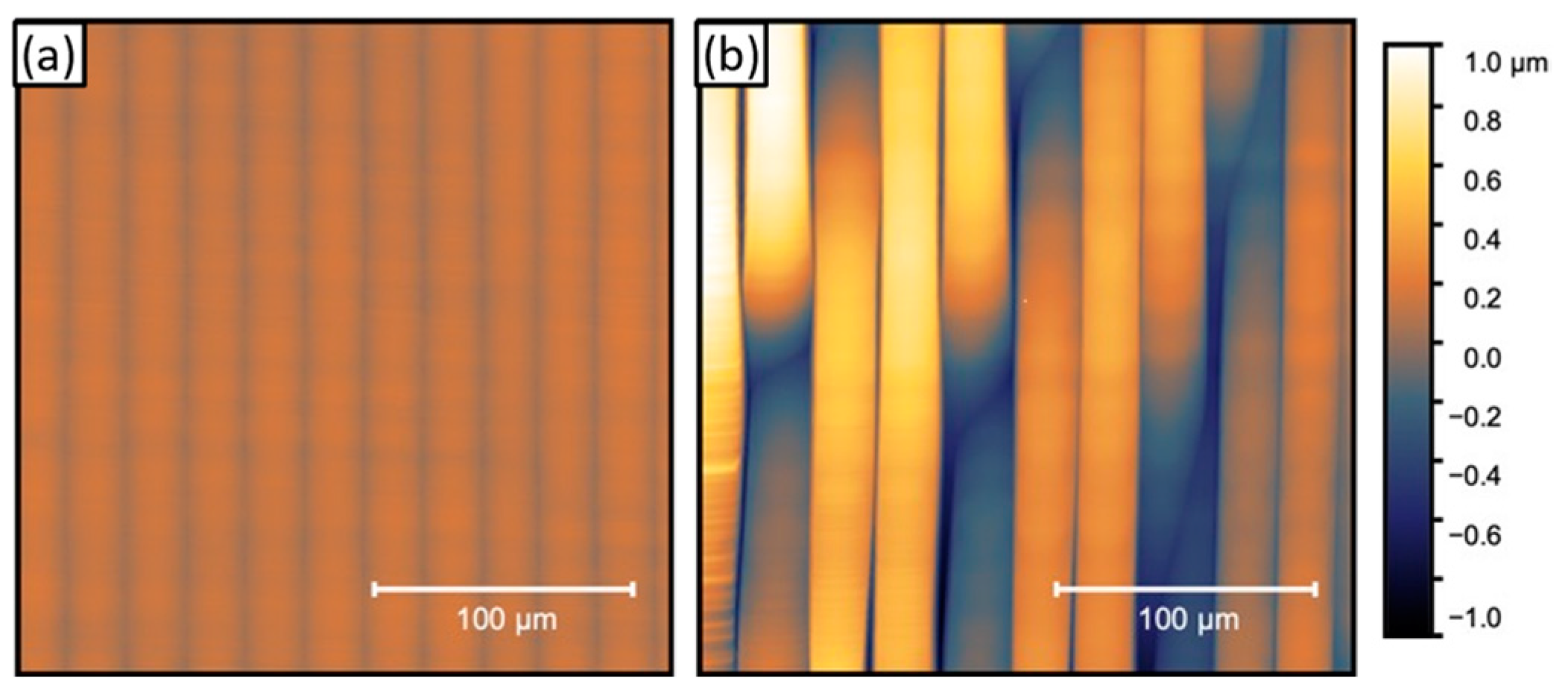
Spalled GaAs wafers result in faceted surfaces with peak-to-trough heights of roughly 6 μm that are inclined at an average angle of ~32° to the [100], indicating that they are likely comprised of a combination of {211}B and {311}B planes, as we observed in other spalled samples [12]. We refer to this facet surface as {n11}, for accuracy and simplicity. We grew upright rear heterojunction solar cells with the planarization layer, as described above, on spalled GaAs. After growth, these cells exhibit predominantly specular surfaces that have a typical Sq roughness of ~40 nm in 100 μm × 100 μm sampled areas as measured with an optical profilometer. Figure 2 shows optical profilometry height maps that indicate the specular areas have no remaining {n11} facets and a nominally (100) surface with a scalloped morphology. The facets are effectively removed and the morphology is flat having no inclination angles larger than a few degrees. However, Figure 2b shows that there are areas of the sample with remaining faceted troughs of a few microns in height. Here, we measure an Sq of ~500 nm in 100 μm × 100 μm sampled areas. We define these cases as ‘complete planarization’ for that of Figure 2a and ‘incomplete planarization’ for that of Figure 2b.
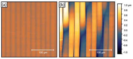
Figure 2.
Optical profilometry height maps of solar cell surfaces for the case of (a) complete and (b) incomplete planarization.
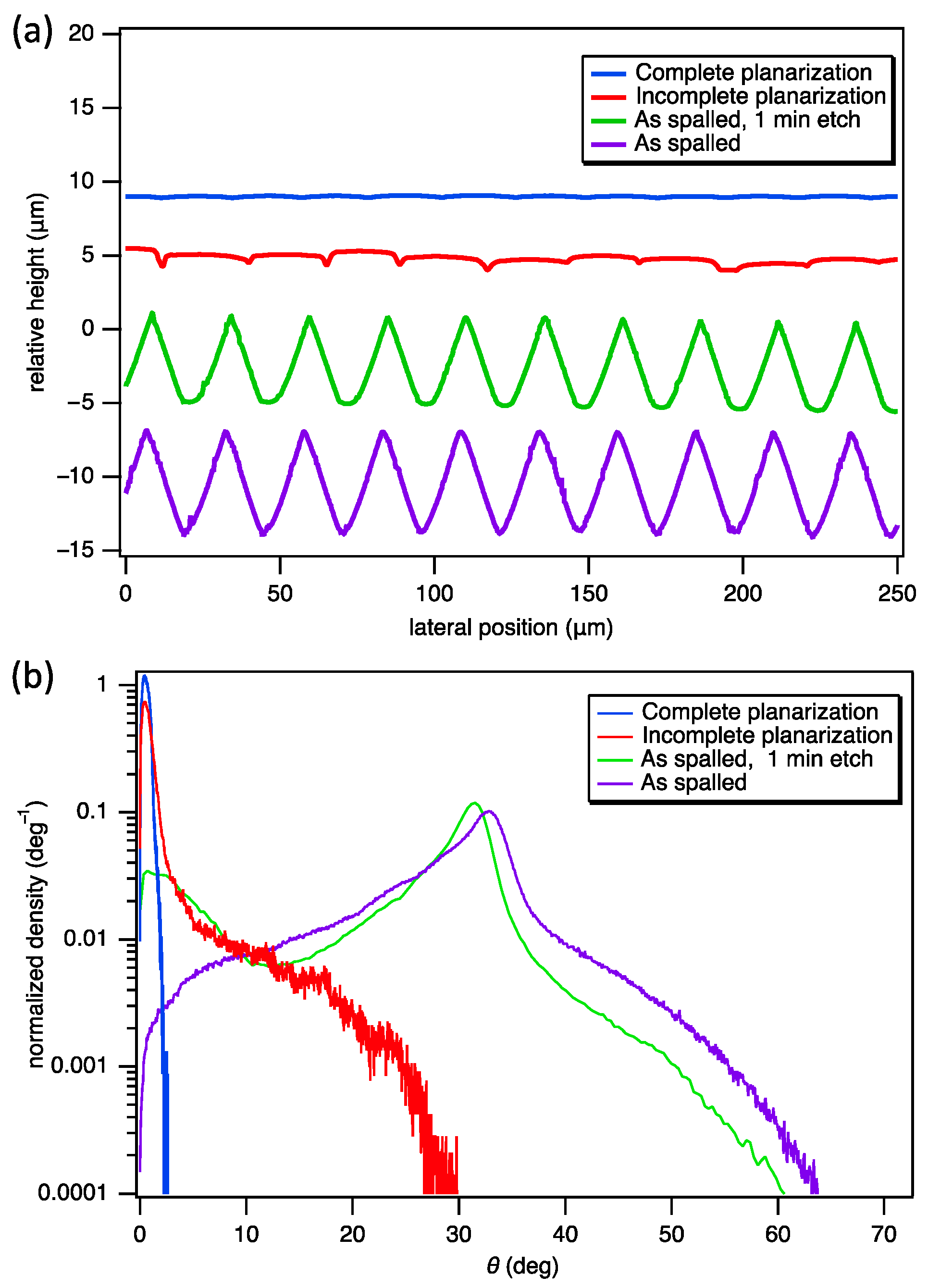
Figure 3a compiles line scans from optical profilometry for complete and incomplete planarization cases, and for the as-spalled surface before and after a 1 min substrate preparation etch in 2:1:10 NH4OH:H2O2:H2O. The substrate preparation etch rounds out the valleys, but contributes little to the overall planarization, as shown by the green profile in Figure 3a. Some of the original faceted troughs in the as-spalled surface persist after the solar cell growth for the incomplete planarization case, whereas they are removed in the complete planarization case. We can infer from the wider spacing between troughs in Figure 2b that the facets underlying the incompletely planarized regions were slightly larger, which likely means that more planarization growth is necessary to completely remove the facets. Non-uniformities in the spall and/or the electroplated Ni stressor layer likely account for this slight variance in facet heights. As such, the planarizing buffer layer, which we targeted to planarize slightly smaller facets, did not accomplish complete planarization in certain areas.
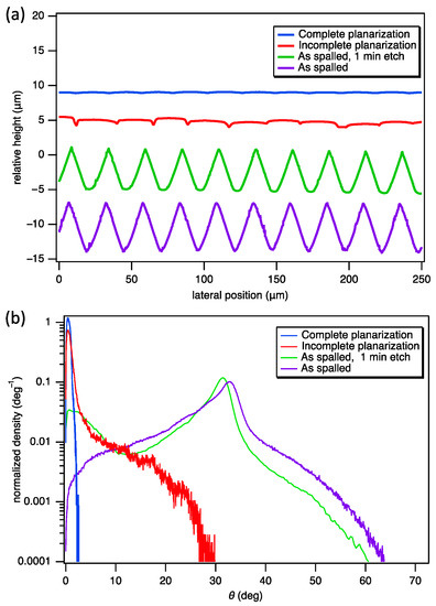
Figure 3.
(a) Line profiles for as-spalled and as-grown solar cell surfaces. Profiles are separated by arbitrary height for viewing clarity. (b) Distribution of angles of the surface normal to the [100].
We measured the distribution of surface inclination angles relative to the surface normal by fitting local planes through each point in optical height maps similar to those in Figure 2. A ~2 μm wide plane was fitted to the local data around each pixel for noise filtration. Figure 3b plots the distribution of the absolute value of the inclination angle, θ, of the surface normal from [100]. Prior to planarizing growth, the as-spalled surface has facets that are predominantly inclined at ~32°. Some higher angle features are present and comprise a few % of the total inclination angle content (note the log scale in Figure 3b). The as-spalled surface after etching increases the occurrence of inclinations below 10° by rounding out the valleys. After planarizing growth, we observe no inclination angles greater than a few degrees for the complete planarization case; however, the incomplete planarization case has an appreciable amount of features inclined up to 30° from the surface normal and is far different from the completely planarized surface.
We used solar cell devices to understand the impact of incomplete planarization on material quality. Solar cells are highly sensitive to crystalline defects over a large area, making them a good indicator of potential problems that occurred during the growth. We fabricated solar cells on a spalled wafer and compared their performance to those grown on an epi-ready substrate. We chose a particular device grown on spalled GaAs that had both areas of complete planarization (as shown in Figure 2a) and incomplete planarization (as shown in Figure 2b) to analyze their spatial impact on the cell performance and material quality. Figure 4 shows the illuminated and dark J-V curves of devices grown on spalled and epi-ready substrates without an anti-reflection coating. The device grown on the epi-ready substrate shows fairly typical performance for this structure. The partially planarized device, however, shows reduced performance in all key metrics. Short circuit current density, JSC, or the value where the curve crosses the y-axis, decreases by ~0.8 mA/cm2, which indicates less photocurrent is produced. Open circuit voltage, VOC, or the voltage at which the curve crosses the x-axis, also decreases by ~60 mV, which indicates higher non-radiative recombination current. These decreases result in a >2% drop in absolute efficiency compared to the control. We then examined the J-V characteristic in the dark to better understand the loss pathways, in particular the VOC and fill factor reduction, of the partially planarized device. Figure 4b shows both devices have similar slopes, which correspond to a diode with ideality of 2. The dark J-V otherwise shows no shunt or series resistance signatures. These devices are limited by a J02 recombination current, which typically corresponds to Shockley–Read–Hall recombination within the depletion region. Overall, the partially planarized device has a ~500× higher J02 dark current compared to the control. This dark current increase suggests that a Shockley–Read–Hall recombination pathway in the depletion region is elevated in the incomplete planarization case [36], which accounts for the loss of ~60 mV in VOC.

Figure 4.
(a) Illuminated and (b) dark J-V curves with (c) extracted metrics for GaAs solar cells without an anti-reflection coating grown on epi-ready and partially planarized spalled substrates.
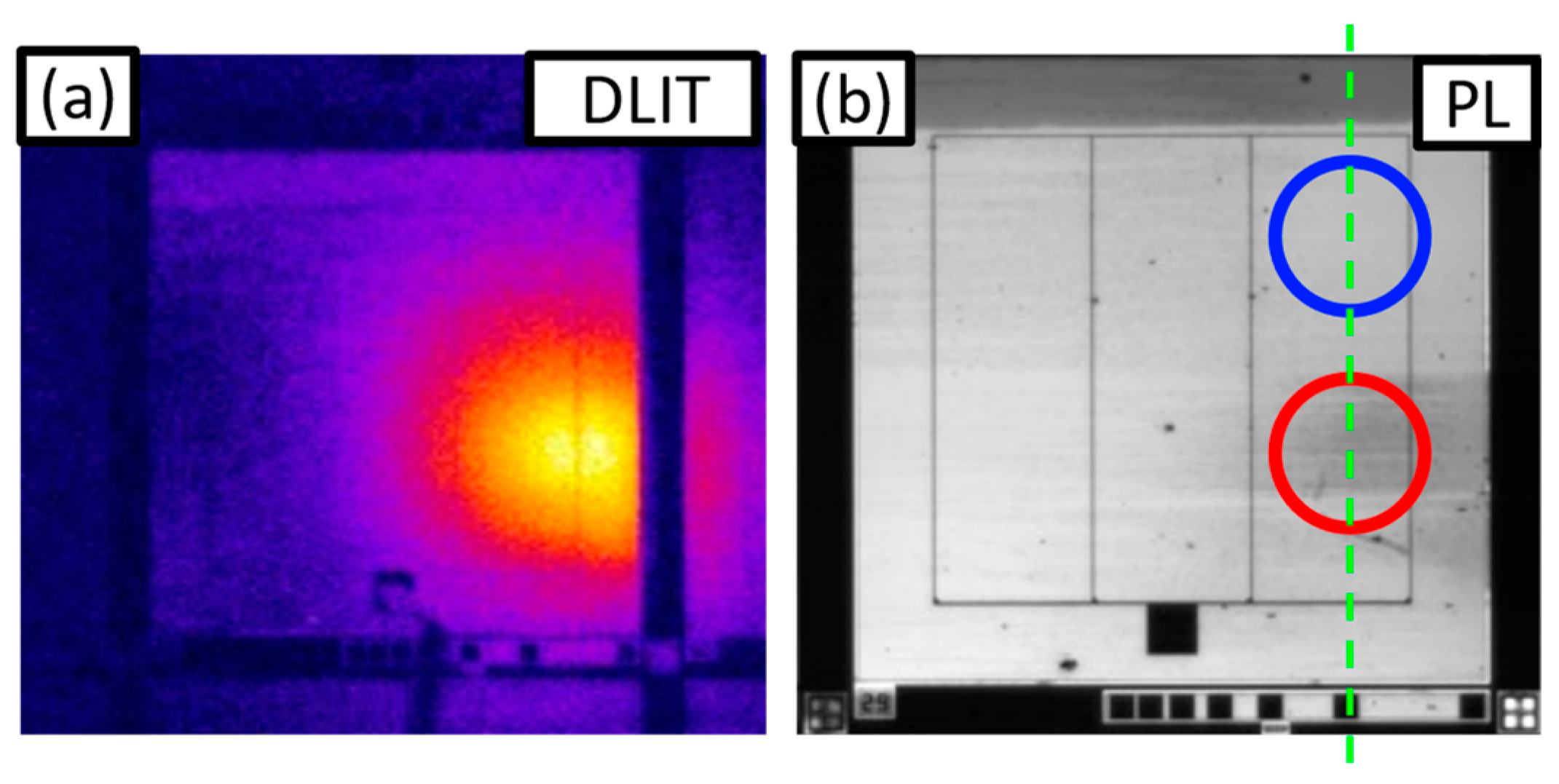
We used DLIT and PL to assess the impact that the areas of incomplete planarization have on the device under test. Figure 5 shows a device grown on spalled GaAs as observed by both DLIT at 20 mA/cm2 forward bias current and PL. We correlated a region of incomplete planarization (Figure 5b, circled in red) to a bright spot in DLIT and dark lines in PL. These indicate local heating due to high current flow and non-radiative recombination in that area, respectively. The location of these spots correlates with the incomplete planarized area; thus, we infer that the increased dark current and reduced photocurrent in the J-V curve originate from regions of incomplete planarization. Both the reduced photocurrent and increased dark current may be the result of extended defects in the active region of the solar cell [37].
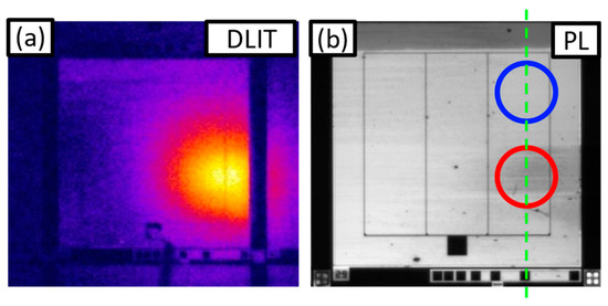
Figure 5.
(a) DLIT and (b) PL images of a GaAs solar cell grown on partially planarized spalled wafers. These DLIT images were taken at a forward bias current of 20 mA/cm2. The blue and red circles in (b) denote complete and incomplete planarized regions, respectively. This device was cleaved approximately through the green dashed line for cross-sectional analysis.
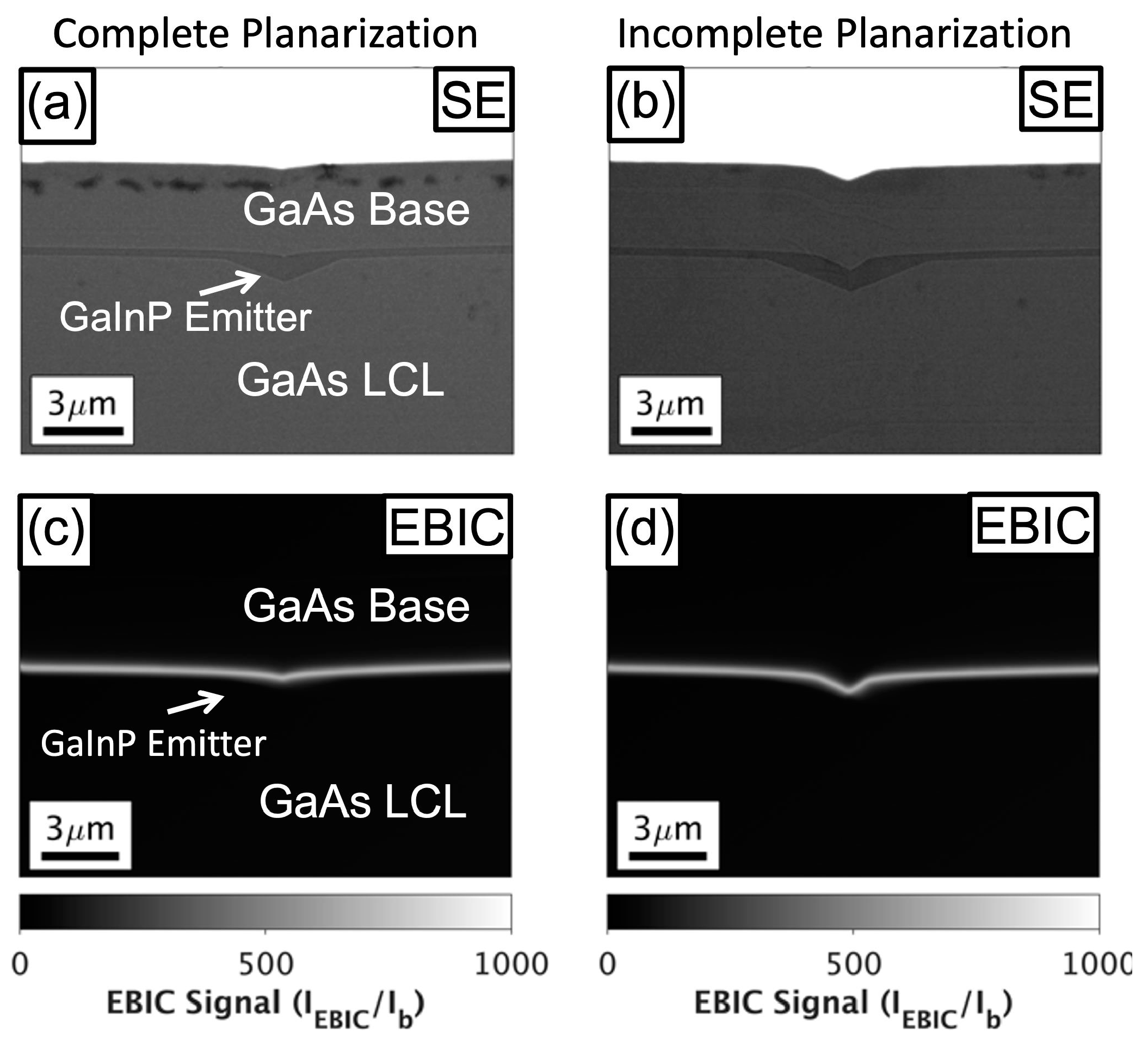
We investigated the extent of the incomplete planarization within the device by imaging cross-sections of representative areas in this cell. Figure 6 shows SEM micrographs of cross-sections of completely and incompletely planarized areas, from the areas marked with blue and red circles in Figure 5b, respectively, indicating different junction (base/emitter interface) shapes. Figure 6a shows a reasonably flat junction and top surface; however, in Figure 6b, we observe that the junction and top surface in this region are not planar. It is apparent in Figure 6b that the GaAs base layer, which used different growth conditions than the planarization LCL layer, did not contribute to planarization, as expected from the growth conditions [31]. Thus, the top surface has essentially the same morphology that is present at the junction. As such, the top surface morphology presented in Figure 2 can gauge the morphology of the junction. We can use the dark J-V data to determine if this non-planar top surface morphology affects the window. Poor passivation, due to a missing or disrupted window layer, would increase the J01 substantially. We do not observe J01-limited dark current behavior that would be consistent with poor front interfacial passivation; thus, we infer the thin window layer at the non-planar top surface is not disrupted. We also do not observe any bright spots in DLIT under reverse bias (not shown) that would indicate the presence of a simple shunt. Given the J02-limited dark current behavior, it is plausible that the dopant or defect concentrations in the depletion region may be altered by the non-planar growth at the junction.
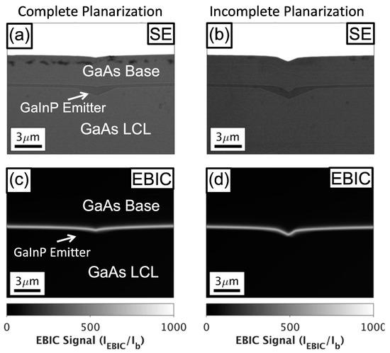
First, we investigated the depletion region using electron-beam-induced current (EBIC). Figure 6c,d show EBIC images of regions with and without complete planarization. We observe a thin bright line of high EBIC signal, which stems from the electric field of the depletion region. All other regions of these images are likely limited by recombination at the surface of the unpassivated cross-section. The depletion region appears conformal and effectively the same thickness in all cases, without disruptions as observed in other cells grown on non-planar surfaces [29].
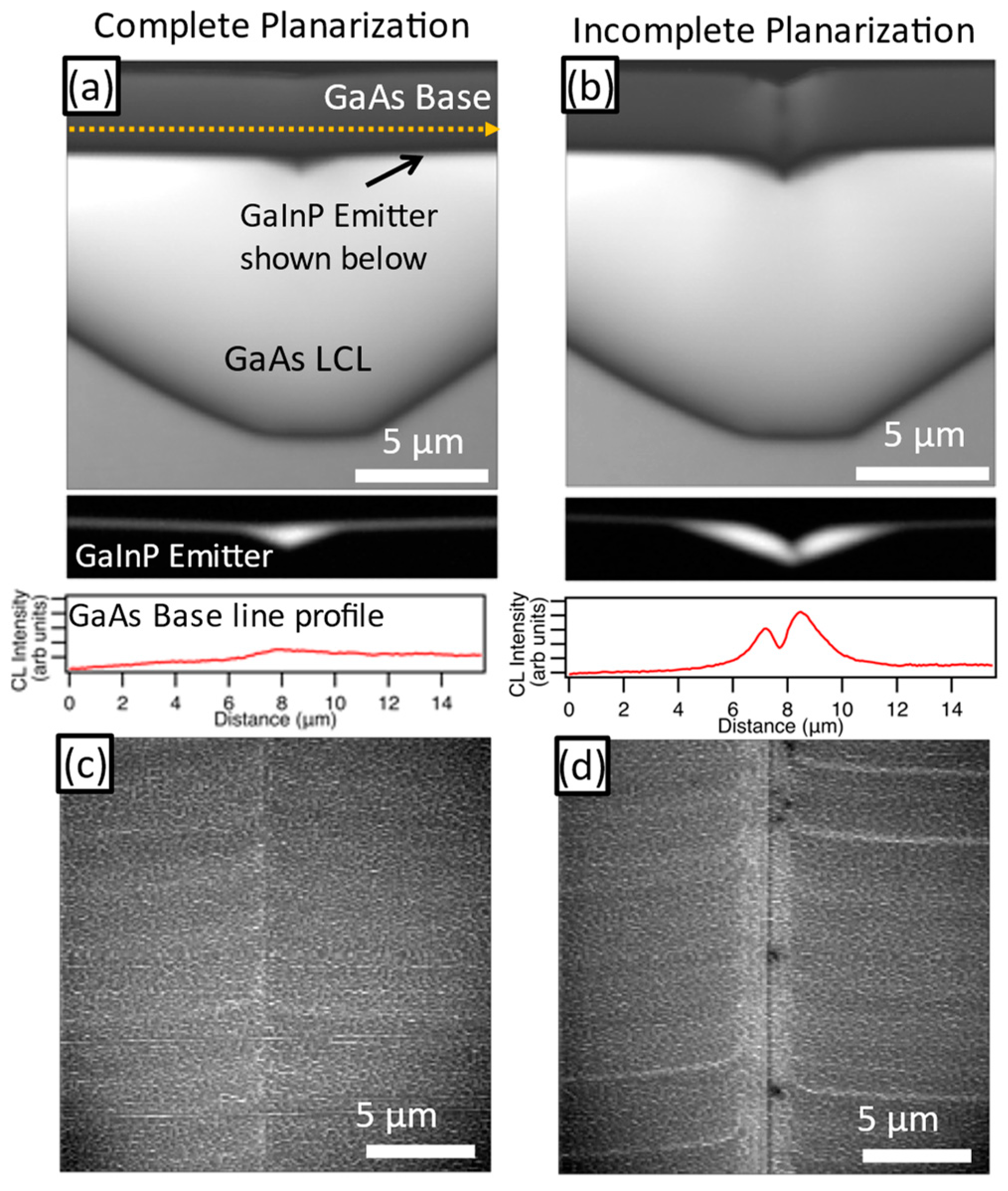
Next, we conducted CL to look for extended defects near the junction on the µm-scale. Similar to the PL, regions that contain a large degree of non-radiative recombination (e.g., dislocations) show up as dark lines or spots in CL images. Figure 7 summarizes the CL intensity images in both the complete and incomplete planarization areas in both cross-section and plan view. Note that the GaInP signal is shown separately below Figure 7a,b. Figure 7a,c shows the completely planarized region, which exhibits a mostly flat intensity signal, except for a slight increase in intensity over the planarized trench. However, the incompletely planarized case, shown in Figure 7b,d, shows dark features in the GaAs base layer in both orientations. The cross-section shows locally reduced CL emission centered in the trench, extending upward from the GaInP emitter through the entire GaAs base. The bright features within the incompletely planarized trench also appear in the plan view SE images, suggesting surface topology accounts for some of this contrast. Nevertheless, the cross-sectional CL (see the line profile in Figure 7b) suggests that the emission around these defects is increased. In plan view, we observe localized dark features aligned along the incompletely planarized trench. The extension of these dark defects from emitter to the top surface and their localized nature in plan view suggests they are likely threading dislocations (TDs). We calculated an overall density of TDs of ~1–2 × 106 cm−2 from the plan view CL images, although they are clearly aligned to the trench and not uniformly distributed. We did not detect any TDs in the images in the completely planarized region. This TD density was shown to decrease the VOC by 50–70 mV in similar GaAs solar cells [37], which correlates well with the 60 mV VOC decrease and J02 increase observed in our solar cells. Recombination will likely be higher near the trenches and lower between trenches due to the clustered distribution of the TDs, leading to dark lines in PL near the trenches, such as those observed in Figure 5b.
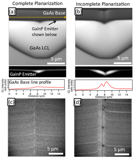
Figure 7.
Cross-sectional CL intensity images of (a) complete and (b) incomplete planarized regions. Horizontal line profiles taken at the approximate location of the arrow are given below each panel. Plan view CL images of (c) complete and (d) incomplete planarized regions.
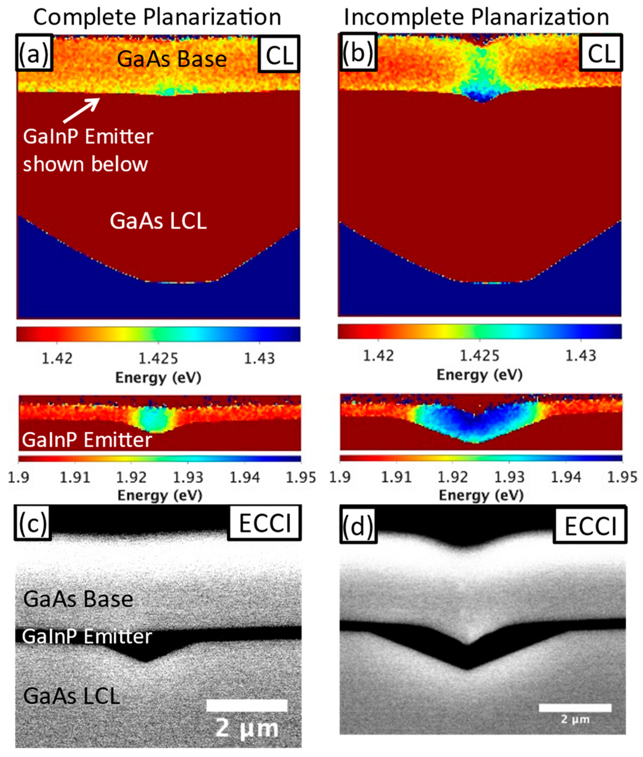
One potential cause of dislocation generation during growth is strain from lattice mismatch related to compositional fluctuations in the material. We probed for compositional fluctuation using spectrally resolved CL, which indicates the emission energy stimulated from a given area and is directly correlated with the local bandgap. Figure 8a,b detail the peak emission energy of the cross-sectional CL images (Figure 7a,b). Here, we observe that the peak emission energy in the GaInP emitter shifts ~40 meV higher in the incomplete planarization case. We also used ECCI in cross-section to investigate any structural defects. Figure 8c shows a slight contrast underneath the GaInP emitter but very little at the junction (base/emitter interface). Figure 8d reveals a stronger contrast on both sides of the emitter, as well as a few features with faint localized bright/dark contrast that could be core signatures of crystalline defect(s) extending from the junction through the GaAs base. This contrast is not visible in conventional SEM imaging modes; therefore, strain is the most likely origin for the ECCI contrast [38].
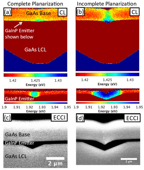
Figure 8.
CL peak emission energy images of (a) complete and (b) incomplete planarized cross-sections. GaInP emitter is shown separately below. ECCI images of (c) complete and (d) incomplete planarized cross-sections.
4. Discussion
Our analysis shows that the decreased solar cell device performance results from the presence of dislocations in the regions with incomplete planarization and residual faceting. The CL and ECCI data offer some clues as to the mechanism by which these defects formed. Cross-sectional CL reveals a blueshift in peak emission energy in both the GaAs base and the GaInP emitter. The distribution of the blueshift in CL and strain in ECCI around and above the non-(100) regions of the GaInP emitter suggest that it is the source of the strain. It is plausible that GaInP growth on {n11}B planes will result in different In and Ga incorporation rates relative to those on (100) due to possible variations in surface adsorption energy, surface reaction rates, or both, similar to observations of Ga-rich GaInP growth by OMVPE on {111}B surfaces [39]. Indeed, the increased GaInP bandgap on the facets implies that it is Ga-rich and that Ga incorporation is locally enhanced on the {n11}B facets. By extension, this leads to a local deviation of the GaInP lattice constant from that of the GaAs substrate (i.e., lattice mismatch) creating tensile strain. To counteract this strain, the GaAs surrounding the non-(100) portions of the GaInP emitter is in slight compressive strain, leading to a blueshift in the GaAs CL emission. This happens because the tensile GaInP, which is strained to a smaller lattice constant, exerts a shear stress on the GaAs. It is also interesting to note that these particular GaInP layers planarize, likely by having a {n11} growth rate that is faster than (100), similar to what we observe in GaAs [31]. This is plausible given prior reports that demonstrate faster GaInP growth on {n11}, depending on growth parameters and growth technique [40].
While both incomplete and complete planarization regions have some degree of strain around non-(100) interfaces, only the incomplete planarization case exhibits dislocations and decreased device performance. The spectrally resolved CL data provide clues as to why. The bandgap fluctuation of 40 meV in the GaInP in the incomplete planarization case implies a composition of Ga0.55In0.45P, ~3.5% higher than the lattice-matched composition [41], which would grow with a lattice strain of ~0.13%. The equilibrium critical thickness, or thickness at which it becomes energetically favorable to relieve epilayer strain by the presence of dislocations, is ~100 nm for this strain [42]. In the fully planarized case the GaInP composition is only Ga0.53In0.47P, implying a strain of only 0.05% and a critical thickness of ~300 nm. The GaInP thickness peaks at ~600 nm in the trench in this case, about 2× the critical thickness; however, dislocation generation may still be unlikely at this thickness given other factors that delay dislocation generation beyond equilibrium critical thickness [43]. The incomplete planarization case has GaInP that is >10× greater than its critical thickness, which implies that dislocation generation will occur. Therefore, the increased strain and the fact that the volume of non-planar GaInP growth is much higher, as seen in Figure 8, suggest that there is a significantly higher probability of dislocation nucleation in the non-planarized case. Furthermore, GaAs nucleated on this strained GaInP encounters an abrupt change in strain, which could also nucleate dislocations. In the fully planarized case, both the lower thickness of GaInP grown on facets and the less abrupt change in strain at the base/emitter interface explain the lack of the formation of extended defects.
These results imply that there is a critical level of planarization that must be reached to enable defect-free device growth. We cannot yet estimate a threshold of inclination angle beyond which these defects are present. However, it seems likely that GaInP or any non-binary alloy, which potentially have growth orientation-dependent composition [39], will introduce mismatch strain when grown on non-(100) surfaces, creating a higher potential for the formation of extended defects. As described earlier, the top surface morphology presented in Figure 2 can gauge the morphology beneath non-planarizing layers, such as the GaAs base, and in turn, the likelihood that extended defects were created at the junction. This observation provides a guideline for growing cells on faceted surfaces, namely that it is beneficial for the surface to be fully planar before the deposition of non-binary alloys. Indeed, we expect that more planarization growth in this particular demonstration would planarize the facets. Other growth techniques and substrate reuse paradigms might not be able to planarize all faceted features due to practical limitations of growth time and material usage necessary to planarize facets of a given size. Thus it is important to consider careful cell design that avoids non-binary alloys on large faceted surfaces.
5. Conclusions
We demonstrate that incompletely planarized spalled surfaces can degrade material quality in subsequently grown solar cells. Specifically, GaInP grown on large non-(100) facets yields extended defects that increase dark current in regions where planarization is incomplete. We correlate growth surfaces with a prevalence of high inclination angles to this underlying degradation mechanism. Solar cells with these regions of incomplete planarization have reduced VOC, which can be fully accounted for by the approximate density of TDs that we observe in plan view CL. This results in locally reduced PL emission, higher dark current, and an overall efficiency loss of ~2% absolute. This work suggests extra care will be necessary for the design and production of solar cells on spalled substrates when it is not possible to remove all of the facets. These investigations into the mechanisms of device degradation will ultimately enable high-performing III-V PV on spalled substrates. This advancement, when combined with low-cost epitaxy by HVPE, provides a promising route to low-cost III-V PV.
Author Contributions
Conceptualization: J.T.B., A.K.B., K.L.S., J.S., M.A.S., C.E.P. and A.J.P.; data curation: J.S., S.W.J. and H.L.G.; formal analysis: J.T.B., A.K.B., K.L.S., J.S., S.W.J. and H.L.G.; investigation: J.T.B., A.K.B., K.L.S., J.S., S.W.J. and H.L.G.; methodology: J.T.B., A.K.B., S.W.J. and H.L.G.; project administration: M.A.S., C.E.P. and A.J.P.; resources: M.A.S., C.E.P. and A.J.P.; software: J.S., S.W.J. and H.L.G.; supervision: J.T.B., K.L.S., J.S., M.A.S., C.E.P. and A.J.P.; validation: J.T.B., A.K.B., K.L.S. and J.S.; visualization: J.S.; writing—original draft: J.T.B. and A.K.B.; writing—review and editing: J.T.B., A.K.B., K.L.S., J.S., S.W.J., H.L.G., M.A.S., C.E.P. and A.J.P. All authors have read and agreed to the published version of the manuscript.
Funding
This work was authored in part by the National Renewable Energy Laboratory, operated by the Alliance for Sustainable Energy, LLC, for the U.S. Department of Energy (DOE) under Contract No. DE-AC36-08GO28308. The information, data, or work presented herein was funded by the DOE’s Office of Energy Efficiency and Renewable Energy (EERE) under Solar Energy Technologies Office (SETO) Agreement Number 38261. This material is also based upon work supported by the National Science Foundation Graduate Research Fellowship Program under Grant No. DGE-1646713. Any opinions, findings, and conclusions or recommendation expressed in this material are those of the author(s) and do not necessarily reflect the views of the National Science Foundation. The views expressed in the article do not necessarily represent the views of the DOE or the U.S. Government.
Data Availability Statement
The data that support the findings of this study are available from the corresponding author upon reasonable request.
Acknowledgments
The authors would like to acknowledge David Guiling for materials’ growth and Evan Wong for cell processing.
Conflicts of Interest
The authors declare no conflict of interest.
References
- Horowitz, K.A.; Remo, T.W.; Smith, B.; Ptak, A.J. A Techno-Economic Analysis and Cost Reduction Roadmap for III-V Solar Cells; NREL/TP-6A20-72103; U.S. Department of Energy Office of Scientific and Technical Information: Oak Ridge, TN, USA, 2018. [CrossRef]
- Ward, J.S.; Remo, T.; Horowitz, K.; Woodhouse, M.; Sopori, B.; VanSant, K.; Basore, P. Techno-economic analysis of three different substrate removal and reuse strategies for III-V solar cells: Techno-economic analysis for III-V solar cells. Prog. Photovolt. Res. Appl. 2016, 24, 1284–1292. [Google Scholar] [CrossRef]
- Simon, J.; Schulte, K.L.; Horowitz, K.A.W.; Remo, T.; Young, D.L.; Ptak, A.J. III-V-Based Optoelectronics with Low-Cost Dynamic Hydride Vapor Phase Epitaxy. Crystals 2018, 9, 3. [Google Scholar] [CrossRef]
- Oshima, R.; Ogura, A.; Shoji, Y.; Makita, K.; Ubukata, A.; Koseki, S.; Imaizumi, M.; Sugaya, T. Ultra-High-Speed Growth of GaAs Solar Cells by Triple-Chamber Hydride Vapor Phase Epitaxy. Crystals 2023, 13, 370. [Google Scholar] [CrossRef]
- Metaferia, W.; Schulte, K.L.; Simon, J.; Johnston, S.; Ptak, A.J. Gallium arsenide solar cells grown at rates exceeding 300 µm h−1 by hydride vapor phase epitaxy. Nat. Commun. 2019, 10, 1–8. [Google Scholar] [CrossRef]
- Adachi, S. Optical Constants of Crystalline and Amorphous Semiconductors; Springer: Berlin/Heidelberg, Germany, 1999. [Google Scholar] [CrossRef]
- Steiner, M.A.; Geisz, J.F.; García, I.; Friedman, D.J.; Duda, A.; Kurtz, S.R. Optical enhancement of the open-circuit voltage in high quality GaAs solar cells. J. Appl. Phys. 2013, 113, 123109. [Google Scholar] [CrossRef]
- Adams, J.G.J.; Elarde, V.C.; Hillier, G.; Stender, C.; Tuminello, F.; Wibowo, A.; Youtsey, C.; Bittner, Z.; Hubbard, S.M.; Clark, E.B.; et al. Improved radiation resistance of epitaxial lift-off inverted metamorphic solar cells. In Proceedings of the 2013 IEEE 39th Photovoltaic Specialists Conference (PVSC), Tampa, FL, USA, 16–21 June 2013; pp. 3229–3232. [Google Scholar] [CrossRef]
- Bauhuis, G.J.; Mulder, P.; Haverkamp, E.J.; Schermer, J.J.; Bongers, E.; Oomen, G.; Köstler, W.; Strobl, G. Wafer reuse for repeated growth of III-V solar cells. Prog. Photovolt. Res. Appl. 2010, 18, 155–159. [Google Scholar] [CrossRef]
- Chen, J.; Packard, C.E. Controlled spalling-based mechanical substrate exfoliation for III-V solar cells: A review. Sol. Energy Mater. Sol. Cells 2021, 225, 111018. [Google Scholar] [CrossRef]
- Kaule, F.; Swoboda, M.; Beyer, C.; Rieske, R.; Ajaj, A.; Drescher, W.D.; Schoenfelder, S.; Richter, J. Laser-assisted spalling of large-area semiconductor and solid state substrates. MRS Commun. 2018, 8, 127–131. [Google Scholar] [CrossRef]
- Haggren, T.; Tournet, J.; Jagadish, C.; Tan, H.H.; Oksanen, J. Strain-Engineered Multilayer Epitaxial Lift-Off for Cost-Efficient III–V Photovoltaics and Optoelectronics. ACS Appl. Mater. Interfaces 2023, 15, 1184–1191. [Google Scholar] [CrossRef]
- Depauw, V.; Porret, C.; Moelants, M.; Vecchio, E.; Kennes, K.; Han, H.; Loo, R.; Cho, J.; Courtois, G.; Kurstjens, R.; et al. Wafer-scale Ge epitaxial foils grown at high growth rates and released from porous substrates for triple-junction solar cells. Prog. Photovolt. Res. Appl. 2022, 1–14. [Google Scholar] [CrossRef]
- Chapotot, A.; Arias-Zapata, J.; Hanus, T.; Ilahi, B.; Paupy, N.; Daniel, V.; El Hmaidi, Z.O.; Chretien, J.; Hamon, G.; Darnon, M.; et al. Multiple substrate reuse: A straightforward reconditioning of Ge wafers after porous separation. In Proceedings of the 2022 IEEE 49th Photovoltaics Specialists Conference (PVSC), Philadelphia, PA, USA, 5–10 June 2022; p. 530. [Google Scholar] [CrossRef]
- Kurstjens, R.; Courtois, G.; Cho, J.; Dessein, K.; Garcia, I.; Rey-Stolle, I.; Algora, C.; Depauw, V.; Porret, C.; Loo, R. GaInP solar cells grown on Ge-on-Ge engineered substrates. In Proceedings of the 2021 IEEE 48th Photovoltaic Specialists Conference (PVSC), Fort Lauderdale, FL, USA, 20–25 June 2021; pp. 0175–0177. [Google Scholar] [CrossRef]
- Park, S.; Simon, J.; Schulte, K.; Ptak, A.J.; Wi, J.-S.; Young, D.L.; Oh, J. Germanium-on-Nothing for Epitaxial Liftoff of GaAs Solar Cells. Joule 2019, 3, 1782–1793. [Google Scholar] [CrossRef]
- Winter, E.; Schreiber, W.; Schygulla, P.; Souza, P.; Janz, S.; Lackner, D.; Ohlmann, J. III-V material growth on electrochemically porosified Ge substrates. J. Cryst. Growth 2023, 602, 126980. [Google Scholar] [CrossRef]
- Kim, Y.; Cruz, S.S.; Lee, K.; Alawode, B.O.; Choi, C.; Song, Y.; Johnson, J.M.; Heidelberger, C.; Kong, W.; Choi, S.; et al. Remote epitaxy through graphene enables two-dimensional material-based layer transfer. Nature 2017, 544, 340–343. [Google Scholar] [CrossRef] [PubMed]
- Coll, P.G.; Neumann, A.; Smith, D.; Warren, E.; Polly, S.; Hubbard, S.; Steiner, M.A.; Bertoni, M.I. Sonic Lift-off of GaAs-based Solar Cells with Reduced Surface Facets. In Proceedings of the 2021 IEEE 48th Photovoltaic Specialists Conference (PVSC), Fort Lauderdale, FL, USA, 20–25 June 2021; pp. 2141–2143. [Google Scholar] [CrossRef]
- Shahrjerdi, D.; Bedell, S.W.; Bayram, C.; Lubguban, C.C.; Fogel, K.; Lauro, P.; Ott, J.A.; Hopstaken, M.; Gayness, M.; Sadana, D. Ultralight High-Efficiency Flexible InGaP/(In)GaAs Tandem Solar Cells on Plastic. Adv. Energy Mater. 2012, 3, 566–571. [Google Scholar] [CrossRef]
- Sweet, C.A.; Schulte, K.L.; Simon, J.D.; Steiner, M.A.; Jain, N.; Young, D.L.; Ptak, A.J.; Packard, C.E. Controlled exfoliation of (100) GaAs-based devices by spalling fracture. Appl. Phys. Lett. 2016, 108, 011906. [Google Scholar] [CrossRef]
- Bedell, S.W.; Shahrjerdi, D.; Hekmatshoar, B.; Fogel, K.; Lauro, P.A.; Ott, J.A.; Sosa, N.; Sadana, D. Kerf-Less Removal of Si, Ge, and III–V Layers by Controlled Spalling to Enable Low-Cost PV Technologies. IEEE J. Photovolt. 2012, 2, 141–147. [Google Scholar] [CrossRef]
- Braun, A.K.; Theingi, S.; McMahon, W.E.; Ptak, A.J.; Packard, C.E. Controlled spalling of (100)-oriented GaAs with a nanoimprint lithography interlayer for thin-film layer transfer without facet formation. Thin Solid Film. 2022, 742, 139049. [Google Scholar] [CrossRef]
- Park, H.; Won, H.; Lim, C.; Zhang, Y.; Han, W.S.; Bae, S.-B.; Lee, C.-J.; Noh, Y.; Lee, J.; Lee, J.; et al. Layer-resolved release of epitaxial layers in III-V heterostructure via a buffer-free mechanical separation technique. Sci. Adv. 2022, 8, eabl6406. [Google Scholar] [CrossRef]
- Mangum, J.S.; Theingi, S.; Neumann, A.N.; McMahon, W.E.; Warren, E.L. Using electron channeling contrast imaging to inform and improve the growth of high-efficiency GaAs solar cells on nanopatterned GaAs substrates. J. Cryst. Growth 2022, 581, 126490. [Google Scholar] [CrossRef]
- Sharma, S.; Favela, C.A.; Yu, B.; Galstyan, E.; Selvamanickam, V. Conversion efficiency improvement of ELO GaAs solar cell, deposited on water soluble sacrificial buffer. Surf. Coat. Technol. 2023, 456, 129282. [Google Scholar] [CrossRef]
- Simon, J.; Frank-Rotsch, C.; Stolze, K.; Young, M.; Steiner, M.A.; Ptak, A.J. GaAs solar cells grown on intentionally contaminated GaAs substrates. J. Cryst. Growth 2020, 541, 125668. [Google Scholar] [CrossRef]
- Cavalli, A.; Alkurd, N.; Johnston, S.; Diercks, D.R.; Roberts, D.M.; Ley, B.E.; Simon, J.; Young, D.L.; Packard, C.E.; Ptak, A.J. Performance of III–V Solar Cells Grown on Reformed Mesoporous Ge Templates. IEEE J. Photovolt. 2021, 12, 337–343. [Google Scholar] [CrossRef]
- Mangum, J.S.; Rice, A.D.; Chen, J.; Chenenko, J.; Wong, E.W.K.; Braun, A.K.; Johnston, S.; Guthrey, H.; Geisz, J.F.; Ptak, A.J.; et al. High-Efficiency Solar Cells Grown on Spalled Germanium for Substrate Reuse without Polishing. Adv. Energy Mater. 2022, 12, 01332. [Google Scholar] [CrossRef]
- Jain, N.; Crouse, D.; Simon, J.; Johnston, S.; Siol, S.; Schulte, K.L.; Packard, C.E.; Young, D.L.; Ptak, A.J. III–V Solar Cells Grown on Unpolished and Reusable Spalled Ge Substrates. IEEE J. Photovolt. 2018, 8, 1384–1389. [Google Scholar] [CrossRef]
- Braun, A.K.; Schulte, K.L.; Simon, J.; Ptak, A.J.; Packard, C.E. Design of Planarizing Growth Conditions on Unpolished and Faceted (100)-Oriented GaAs Substrates Using Hydride Vapor Phase Epitaxy. Cryst. Growth Des. 2023, 23, 1195–1204. [Google Scholar] [CrossRef]
- Cavalli, A.; Ley, B.; Johnston, S.; Sulas, D.; Simon, J.; Schulte, K.L.; Packard, C.E.; Young, D.L.; Ptak, A.J. GaAs Solar Cells Grown on Unpolished, Spalled Ge Substrates. In Proceedings of the 2018 IEEE 7th World Conference on Photovoltaic Energy Conversion (WCPEC) (A Joint Conference of 45th IEEE PVSC, 28th PVSEC & 34th EU PVSEC), Waikoloa Village, HI, USA, 15 June 2018; pp. 2771–2775. [Google Scholar] [CrossRef]
- Simon, J.; Young, D.; Ptak, A. Low-cost III–V solar cells grown by hydride vapor-phase epitaxy. In Proceedings of the 2014 IEEE 40th Photovoltaic Specialist Conference (PVSC), Denver, CO, USA, 8–13 June 2014; pp. 538–541. [Google Scholar] [CrossRef]
- Boyer, J.T.; Schulte, K.L.; Young, M.R.; Ptak, A.J.; Simon, J. AlInP-passivated III–V solar cells grown by dynamic hydride vapor-phase epitaxy. Prog. Photovolt. Res. Appl. 2022, 31, 230–236. [Google Scholar] [CrossRef]
- Mukherjee, K.; Wacaser, B.A.; Bedell, S.W.; Sadana, D.K. Rapid imaging of misfit dislocations in SiGe/Si in cross-section and through oxide layers using electron channeling contrast. Appl. Phys. Lett. 2017, 110, 232101. [Google Scholar] [CrossRef]
- Geisz, J.; Steiner, M.A.; Garcia, I.; Kurtz, S.R.; Friedman, D. Enhanced external radiative efficiency for 20.8% efficient single-junction GaInP solar cells. Appl. Phys. Lett. 2013, 103, 041118. [Google Scholar] [CrossRef]
- Andre, C.L.; Wilt, D.M.; Pitera, A.J.; Lee, M.L.; Fitzgerald, E.A.; Ringel, S.A. Impact of dislocation densities on n+∕p and p+∕n junction GaAs diodes and solar cells on SiGe virtual substrates. J. Appl. Phys. 2005, 98, 014502. [Google Scholar] [CrossRef]
- Wilkinson, A.J.; Hirsch, P.B. Electron diffraction based techniques in scanning electron microscopy of bulk materials. Micron 1997, 28, 279–308. [Google Scholar] [CrossRef]
- Martínez, O.; Hortelano, V.; Jiménez, J.; Parra, V.; Pelosi, C.; Attolini, G.; Prutskij, T. Effect on Ordering of the Growth of GaInP Layers on (111)-GaAs Faces. J. Electron. Mater. 2010, 39, 671–676. [Google Scholar] [CrossRef]
- Tateno, K.; Uenohara, H.; Kagawa, T.; Amano, C. Characteristics of the GaInP burying layers grown by metalorganic chemical vapor deposition on mesa-patterned GaAs substrates. J. Cryst. Growth 2000, 209, 605–613. [Google Scholar] [CrossRef]
- Yoon, S.; Mah, K.; Zheng, H. The effect of elastic strain on the optical properties of InGaP/GaAs grown using a valved phosphorus cracker cell in solid source MBE. J. Alloys Compd. 1998, 280, 299–305. [Google Scholar] [CrossRef]
- Matthews, J.W.; Mader, S.; Light, T.B. Accommodation of Misfit Across the Interface Between Crystals of Semiconducting Elements or Compounds. J. Appl. Phys. 1970, 41, 3800–3804. [Google Scholar] [CrossRef]
- Ward, T.; Sánchez, A.M.; Tang, M.; Wu, J.; Liu, H.; Dunstan, D.J.; Beanland, R. Design rules for dislocation filters. J. Appl. Phys. 2014, 116, 063508. [Google Scholar] [CrossRef]
Disclaimer/Publisher’s Note: The statements, opinions and data contained in all publications are solely those of the individual author(s) and contributor(s) and not of MDPI and/or the editor(s). MDPI and/or the editor(s) disclaim responsibility for any injury to people or property resulting from any ideas, methods, instructions or products referred to in the content. |
© 2023 by the authors. Licensee MDPI, Basel, Switzerland. This article is an open access article distributed under the terms and conditions of the Creative Commons Attribution (CC BY) license (https://creativecommons.org/licenses/by/4.0/).

