Abstract
Depending on operating conditions, metals and alloys are exposed to various factors: wear, friction, corrosion, and others. Plasma surface alloying of machine and tool parts is now an effective surface treatment process of commercial and strategic importance. The plasma surface alloying process involves adding the required elements (carbon, chromium, titanium, silicon, nickel, etc.) to the surface layer of the metal during the melting process. A thin layer of the compound is pre-applied to the substrate, then melted and intensively mixed under the influence of a plasma arc, and during the solidification process, a new surface layer with optimal mechanical properties is formed. Copper-based alloys—Cu-X, where X is Fe, Cr, V, Nb, Mo, Ta, and W—belong to an immiscible binary system with high mechanical strength, electrical conductivity, and magnetism (for Fe-Cu) and also high thermal characteristics. At the same time, copper-based alloys have low hardness. In this article, wear tests were carried out on coatings obtained by plasma alloying of CuSn10 and CrxCy under various friction conditions. The following were chosen as a modifying element: chromium carbide to increase hardness and iron to increase surface tension. It is noted that an increase in the chromium carbide content to 20% leads to the formation of a martensitic structure. As a result, the microhardness of the layer increased to 700 HV. The addition of CuSn10 + 20% CrxCy and an additional 5% iron to the composition of the coating improves the formation of the surface layer. Friction tests on fixed abrasive particles were carried out at various loads of 5, 10, and 50 N. According to the test results, the alloy layer of the Fe-Cr-C-Cu-Sn system has the greatest wear resistance under abrasive conditions and dry sliding friction conditions.
1. Introduction
Copper can be used in many engineering fields to make key industrial components in the electrical, electronics, aviation, and automotive sectors, such as heat exchangers, air conditioners, bearings, and underground heating systems, due to its outstanding thermal and electrical conductivity, high melting point, and corrosion resistance.
It is known that one of the main factors influencing the performance characteristics of machine parts and elements and determining their service life is the properties of the surface layer. Improving the performance characteristics and increasing the service life of products in various industries is possible due to the formation of layers on their surface that have a high level of required properties—hardness, wear resistance, and heat resistance [1,2]. Currently, copper-based alloys have high anti-friction properties, but concerns about their softness and high cost lead to limited use in industries where high levels of microhardness are required. One of the effective ways to replace bronze materials and improve the anti-friction properties of steel is the use of alloys based on iron and copper (Fe-Cu). The increase in the hardening properties of cast iron is associated with the method of alloying with chemical elements that do not form carbides. The most widely used surface alloy for cast irons is copper. It is known that materials based on Fe-Cu belong to pseudo-alloys that can provide high wear resistance and a low coefficient of friction [1,2,3,4]. The use of a mixture of copper and iron alloys allows the creation of high-quality materials due to the combination of high friction, corrosion-resistant copper alloys and the high strength and low cost of iron alloys. However, in practice, the created alloys of the Fe-Cu system often have a number of disadvantages: layered and heterogeneous structure, limited hardness, a high probability of defects, and a tendency to pitting due to the formation of galvanic vapors between iron and copper [5,6,7,8]. Successful results of steel-bronze pseudo-alloys and surface alloying of cast iron with copper indicate the possibility of creating Fe-Cu-Sn system coatings with improved hardening properties on the surface of parts and tools [9,10,11,12,13,14,15].
Graphene has been found to be an excellent reinforcement material with excellent performance. In [16], nickel-reinforced graphene was produced as a self-lubricating material. The results of this study showed that adding a certain amount of nickel-reinforced graphene increases the tribological properties of copper [17]. The results of the study also introduced the MoS2 effect into copper to form pins and measured its tribology according to AISI 52100. An optimization study was carried out to determine the ideal content quantity. In [18], they tried to add Ti2SnC particles characterized by improved electrical and mechanical properties. Significant improvements were observed in wear rate and coefficient of friction.
Most works study the alloying factors of bronze [10,11,12,19,20,21,22]. In [12,22], plasma melting of a bronze–chromium alloy was used. An increase in the hardness of the composition and an increase in wear resistance when tested for abrasive wear on a fixed abrasive was shown. In [19], a composition of graphite and bronze is used to assess the conditions of friction and mass loss. A team of researchers [20] examined bronze composites under various test conditions, adding aluminum oxide to evaluate surface roughness, wear, and friction mechanisms. The authors of [21] worked on the tribological evaluation of bronze/PLA composites for tribological and tensile testing. As can be seen from the open literature, several reinforcements have been applied to bronze composites, but this topic still requires further study due to the versatility of composite materials.
Due to the fact that pseudo-alloys of the Fe-Cu system have low corrosion resistance compared to copper alloys due to the presence of the active corrosive agent Fe, the introduction of other elements (Cr, Ni, Al, etc.) into the matrix of iron–copper alloys makes it possible to improve not only strengthening properties but also corrosion resistance [5,7,8,15,16,17]. Among them, chromium is the main element that provides several suitable properties for developing iron and copper-based surface designs. It is known that metal–ceramic composites or metal–ceramics combine the hardness of ceramics and the strength of the metal. In particular, carbide compounds, such as WC, Ti3SiC2, TiC, SiC, TiCN, and B4C, are often used in combination with copper alloys to produce composite materials [18,19,20,21,22]. These carbides are added as refractory phases to the copper matrix of copper-carbide composite materials. Chromium carbide is widely used in the production of carbide, which is used in tools for cutting and drilling metals. Hard alloys based on chromium carbide have high hardness, wear resistance, and sharp cutting edges.
The authors of [23] studied the laser cladding process of NAB on NAB substrate in an underwater environment by adding Ti and applying a protective layer of Zn. The fabricated layer had favorable characteristics, and the microstructure was fine, uniform, and stable. In [24], laser surfacing of spherical tungsten carbides on an aluminum bronze substrate was studied. It was shown that, depending on the energy consumption per unit length, unwanted melting of the particles occurs [25]. Used laser surface hardening to modify the surface microstructure of cast nickel-aluminum bronze. As a result, a layer of supersaturated solid solution with small grains 30–50 μm in size was formed. It has been established that laser surface hardening ensures homogenization of the distribution of elements among the phases of the microstructure. In [26], the effect of laser cladding on the properties and frictional behavior of a copper-based coating with mixed additives of graphite from the self-fluxing alloy Ni276 and MoS2 powders was studied. It was found that laser cladding provides a compact structure without cracks, and the wear rate is reduced by ~60% compared to traditional technology. Another work [27] assessed the effect of laser surface modification of Ni and Cr on the microstructure and tribological behavior of gray cast iron. A fine-grained homogenized microstructure of the surface layer with a hardness 3.6 times greater than that of the base material was observed. Laser coatings of Ni and Cr improve abrasion resistance through microstructure modification, martensite formation, and grain fragmentation.
In terms of energy and technical and economic indicators, one of the effective methods of surface hardening of metals using highly concentrated sources is plasma alloying [8,12,13,14,15,16,17,18,23,24,25,26,27,28,29,30,31,32,33,34]. Plasma treatment has a number of advantages: short processing time; high efficiency factor (efficiency); sequential heat treatment is not always required; low requirements for surface preparation before processing; and low cost of equipment [23,24,26,35,36,37,38,39,40].
The purpose of the work is to increase the hardness and wear resistance of the surface of low-carbon structural steel by creating an alloy layer during plasma heating in the fusion mode using a composition of bronze and chromium carbide. The work involved studying the microstructure, measuring microhardness, determining the chemical composition in local areas of the alloyed layers, and wear tests under conditions of abrasive wear and dry sliding friction.
2. Experimental
2.1. Preparing the Coating
Bronze and chromium carbide powder were used as alloying elements. The addition of iron powder allows for the formation of a melt bath with alloying elements evenly distributed in it. The chemical composition and size of the powders are shown in Table 1. The powders of bronze, chromium carbide and iron were mixed in a Pulverisette 6 planetary ball mill with a rotation speed of 200 rpm for 10 min.

Table 1.
Chemical composition of the alloy PRV-BrO10 and chromium carbide.
Then, the powder mixtures were mixed with glue. The ratio of glue and amount of powder should provide the required consistency to obtain a thick paste for easy application to the surface of metals. The thickness of the coating was fixed on the surface of St3 steel using a mask of different relative thicknesses: 0.25 and 0.5 mm. The prepared samples were dried in a ShS-80-01 SPU drying cabinet for 1 h at a temperature of 100 °C to completely remove moisture from the coating. The mode of the surface plasma alloying process is given in Table 2.
Table 2.
Plasma alloying process mode.
2.2. Microstructure Research
The microstructure was studied using a MicroMet2 microscope and an Olympus GX41A digital microscope at a magnification of ×500, ×100, ×200, ×500 and ×1000. Electron microscopic studies were carried out using a JIB-4501 JEOL electron microscope equipped with an energy dispersive spectrometer (EDS). The signal processing system separates the X-ray photons by energy and thus obtains a full spectrum, from which we judge the elemental composition of the target sample. Microhardness measurements were carried out using a SHIMADZU HMV-2 microhardness tester.
2.3. Wear Test in Abrasive Condition
Assessment of the wear resistance of coatings after plasma alloying is carried out using a Struers Tegramin-25 machine (Figure 1b). Samples with doped layers were cut out in the form of a parallelepiped measuring 12 × 5 × 10 mm (Figure 1a). Then, they were pressed into resin to secure them to the friction machine. During testing, the samples are completely pressed against abrasive sandpaper made of silicon carbide mounted on a rotating disk.

Figure 1.
Grinding and polishing machine Struers Tegramin-25 for wear testing. (a) sample (b) testing machine scheme.
2.4. Dry Friction Wear Test
Wear resistance under conditions of sliding friction according to the “block on a ring” scheme was determined using the universal multifunctional system UFW200 (Figure 2). Hardened steel 45 with a hardness of 62 HRC was used as a counterbody. This counter housing has a diameter of 20 mm and a width of 10 mm. St3 steel was used as a comparison sample. The surface of the samples under study was polished with sandpaper. Before testing, the polished surface roughness of all tested samples was 0.32. After each wear volume measurement, the ring and samples were cleaned with acetone using an ultrasonic unit.

Figure 2.
Scheme for testing samples with an alloyed layer under conditions of dry sliding friction.
In all cases, a single load of 100 N was applied to the sample at a rotation speed of 500 rpm. The testing time for one sample with a fused layer was 3 h. During the first 90 min of the test process, the wear hole parameters were measured every 10 min. The wear volume V (cm3) was calculated using the Formula (1) [12,16]:
where l—length of the hole, mm; R—radius of the counterbody, mm; d—thickness of the abrasive ring (counterbody), mm. The surface of the studied samples and the length of the hole were measured using an optical profilometer Contour GT-K1.
3. Results and Discussion
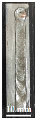
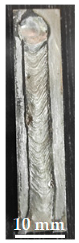
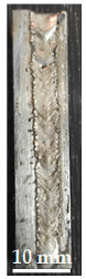
Experiments were carried out with plasma heating of mixtures of CuSn10 + CrxCy alloys in the form of coating with the addition of different contents of chromium carbide: 10, 20, 30, and 40%. After the plasma treatment of the samples, the surface view of the doped tracks and the cross-section of the samples are presented in Table 3.
Table 3.
Appearance of the surface of a single-pass track of plasma layers based on mixtures of CuSn10 + CrxCy alloy.
Alloyed layers based on bronze have a thickness of more than 1240 µm and layers based on a mixture of CuSn10 + CrxCy—about 900 µm. This is explained by the fact that the CuSn10 alloy has a low melting point (about 1000 °C) and smaller particles, which melt faster during plasma heating than chromium carbides, which have a higher melting point and many large particles with a size of 200–300 microns. Three main components are involved in the formation of alloyed layers: bronze alloy (CuSn10), chromium carbide (CrxCy), and iron Fe, which is partially the surface layer of the substrate (steel St3). However, due to the immiscible properties of Fe-Cu system alloys, the formed alloy layer consists of two regions, including one Cu-Sn and the other Fe-Cr-C.
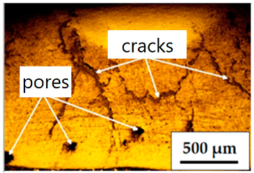
Thus, the quality of the doped layers depends significantly on the ratio and mutual solubility of the participating components at high temperatures. The use of a mixture of bronze and chromium carbide in the process of preparing and applying a layer to the metal surface leads to a non-uniform coating compared to coating prepared from individual components (PRV-BrO10 or chromium carbide). As a result, the resulting layers No. 1 and 2 have an upper thin sublayer (Table 4), and defects (cracks, pores) were observed in layers No. 3 and 4. Obviously, 20% chromium carbides in the mixture is the maximum limit. The distribution of microhardness over the depth of layers obtained after plasma alloying with a current of 120 A is shown in Figure 3 and Figure 4. It was noted that the alloy layer contained predominantly molten tin and bronze with a minor base metal since the power was considerable. The microstructure of steel after alloying has characteristic zones. In the near-surface zone, saturated tin and bronze have microhardness below 200 HV. The zone with a thickness of less than 30 microns near the boundary with the base metal is characterized by a mixture of tin bronze with iron and a large spread of microhardness, the maximum value of which is 507 HV. The same microstructure (Figure 3) was obtained after alloying steel with tin bronze in [27,28]. Increasing the current to 140 A leads to a strong mixing of the powder mixture with the base metal. It is noted that the microstructure of the alloyed layer changes significantly, and the microhardness increases by two times. No defects in the form of delaminations were found. There are several local zones of enrichment in tin and bronze, several hundredths of a micrometer in size.
Table 4.
Characteristics of alloyed layers after plasma treatment.

Figure 3.
Microstructure and microhardness of layers after plasma alloying of steel with bronze: (a) current 120 A, paste thickness 0.25; (b) current 120 A, paste thickness 0.5 mm; (c) current 140 A, paste thickness 0.25 mm; (d) current 140 A, paste thickness 0.5 mm.

Figure 4.
Microstructure and change in microhardness of the surface layer of steel after plasma alloying with tin bronze and 20% chromium carbide.
Figure 4 shows the structure of the alloyed layer made from a mixture of CuSn10 + 20% CrxCy with a paste thickness of 0.25 mm. It is noted that the main structure is equiaxed and columnar crystalline grains. The microhardness values for the central, marginal, and marginal zones differ slightly and are in the range of 500–700 HV. Figure 5 shows photographs taken on an electron microscope with the determination of chemical elements in the surface layer. Figure 5a shows the CuSn10 system. Figure 5b shows the CuSn10 + 20% CrxCy system. The main element in the matrix distribution is iron. The chromium content in the bronze-rich zone is significantly lower than in the iron-rich zone in Figure 5. The tendency to form complex carbides can cause a decrease in the solubility of chromium in the bronze matrix.
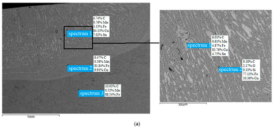
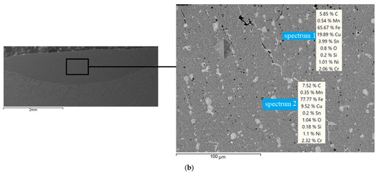
Figure 5.
Chemical composition of the alloyed layers after treatment: (a) CuSn10; (b) CuSn10 + 20% CrxCy.
Abrasive wear resistance. It is known that the structure of the alloy layer determines the ability to resist wear under abrasive conditions. According to the literature [12,23,24,25], depending on the coating, the wear process has its own peculiarity. In this work, the surface condition of the sample and resistance to abrasive wear will change with the depth of the alloyed layer since it consists of an alloyed zone, HAZ, and base metal.
The rotation speed of the disk and holder was set at 100 rpm, and the sample load varied at 5, 10, and 15 N. The results presented in Figure 5 show different behavior. Under a load of 5 N (Figure 6a), the CuSn10 + CrxCy alloyed layers experience higher weight loss compared to the Cu-Sn layer. Although Cu-Sn has the least mass loss, its rate increases linearly, while other layers show a decrease over time. When the load increases by four times (20 N), the mass loss of Cu-Sn exceeds the mass loss of the CuSn10 + CrxCy layers, and the rate of its loss remains linear. This is explained by the high homogeneity of the Cu-Sn layer. All alloyed layers show greater weight loss than at 5 N (Figure 6b). In initial experiments, the low wear resistance of the CuSn10 layer could be due to cracks or unexpected inclusions. When studying the wear surfaces of tested materials containing CuSn10 in different proportions, it is clear that the surface structure of materials containing only CuSn10 is different [12,22]. First of all, the wear characteristics were influenced by surface hardness and porous structure, which are among the most important parameters affecting wear behavior [12]. The results of a study [22] examining the influence of manufacturing parameters on Brinell hardness and porosity values support these interpretations.

Figure 6.
Weight loss over time at different loads: (a) load 5 N; (b) load 20 N; (c) load 50 N.
In the microhardness measurements carried out, it was established that the hardness values increase in parallel with the increase in the mass content of Cr% particles in the CuSn10 + CrxCy system. Conversely, the presence of chromium carbide in the CuSn10 + CrxCy layer increases wear resistance. This alloy layer not only exhibits outstanding wear resistance initially but also maintains it over time, flexing more than other layers. An increase in test time suggests that the internal sublayers are saturated with the reinforcing component, which reduces the number of defects. Other studies of copper permeability in iron and chromium diffusion in steel have yielded similar results. A load of 50 N with measurements every 10 min checks the wear resistance to abrasion (Figure 6c). The CuSn10 and CuSn10 + CrxCy plasma layers continue to show good wear resistance, with the latter showing the best results. Specimens reinforced with chromium particles were found to make a significant positive contribution when comparing wear resistance to pure copper specimens. Conversely, the wear process of the Cu-Sn layer quickly reaches the heat-affected zone, reaching the main zone of St3 steel within 40 min of testing.
Upon examination, the presence of microgrooves in wear zones was revealed, representing distinct scratches of varying lengths and depths. The abrasive particles cause micro-cutting, leaving grooves and sharp-edged blades on the surface of the specimen after wear, aligning with the movement of the abrasive grains. It is noteworthy that scratches and peeling of fragments were observed on the surface of the sample with a Cu-Sn doped layer, which indicates low cohesive strength. This weakness is attributed to the formation of oxide layers at grain boundaries. The observed marks suggest that during wear, the cohesive integrity of the Cu-Sn layer is compromised, possibly due to the action of abrasive particles and the formation of oxide layers, leading to the appearance of scratches and peeling of fragments.
Wear test under sliding friction conditions. After the test interval, the surface of the test samples and the length of the hole were measured using an optical profilometer, “Kontur GT-K1” (Figure 7). The dependence of the volume of worn material on the length of the friction path is presented in Figure 8. It can be seen that the base material (steel St3) has the largest volume of wear pits. This volume was 9 mm3 with a friction path length of 5000 m.

Figure 7.
Wear profile on the block after testing the material with an alloyed Fe-Cr-C-Cu-Sn layer in a dry state of friction: (a) Fe-Cu-Sn; (b) steel st3; (c) Fe-Cr-C-Cu-Sn; (d) casting bronze.

Figure 8.
Volumetric wear of alloyed layers during tests under conditions of dry sliding friction.
It is noted that the friction coefficient for different materials varies significantly, and for St3 steel, it is 0.36; for cast bronze—0.34; for the alloyed Cu-Sn layer—0.32; for the layer of the Fe-Cu-Sn system—0.29; for the Fe-Cr-C-Cu-Sn layer—0.22. It was found that all layers of the alloy have higher wear resistance than the base steel (control sample). After a friction path of 3200 m, the sample with a Cu-Sn alloy layer wears faster than the sample with a Fe-Cu-Sn alloy layer. This value of the two layers is then increased faster using straight parallel lines. The alloyed layer of the Fe-Cr-C-Cu-Sn system has the greatest wear resistance. Up to 1000 m of friction path length, the volume of wear holes increases rapidly, after which it linearly increases more slowly and reaches 2.46 mm3 at a friction path length of 5600 m.
The surface roughness of the samples (Ra) shown in Figure 9 decreases over several alloy layers of the systems: Cast bronze (1.035) > Cu-Sn (0.765) > Fe-Cu-Sn (0.524) > Fe-Cr-C-Cu-Sn (0.358). The roughness of the reference sample after dry friction tests is significantly higher than that of the samples after alloying with CuSn10 and chromium carbide and amounts to 1.761. The minimum roughness value (Ra = 0.358) was determined for a sample with an alloyed layer of the Fe-Cr-C-Cu-Sn system.

Figure 9.
Topography of wear surfaces of alloyed layers: (a) counterbody (hardened steel 45); (b) St3 steel (reference); (c) foundry bronze; (d) Cu-Sn layer; (e) Fe-Cu-Sn layer; (f) Fe-Cr-C-Cu-Sn layer.
Figure 10 shows microscopic images of wear marks on the steel and alloy layers. High-hardening particles in the alloy layer contact the surface of the counterbody during wear and act on it as micro-cutters, removing material with the formation of wear products. Figure 10a,b shows traces in the form of scratches and depressions left on the surface of the sample with a doped Cu-Sn layer. For the alloyed layers of the Fe-Cu-Sn and Fe-Cr-C-Cu-Sn systems, traces of microcutting and oxidation of the smallest size are observed, where the alloyed layer of the Fe-Cr-C-Cu-Sn system has. The Sn system has the greatest wear resistance (see Figure 10c,d). The high temperature and intense vibration experienced during dry wear testing promote oxidation of metal debris and result in severe abrasion. The composite materials we have obtained based on copper and chromium are superior to composite materials with tungsten, molybdenum, and graphite in terms of porosity, high strength, hardness, and wear resistance [1,2,41,42,43,44,45,46]. The wear resistance of bronze composites increases accordingly with the increase in reinforced chromium. Maximum wear resistance was observed when 20 wt% chromium reinforcement was added to the bronze matrix [47]. The presence of chromium additives in composite coatings belonging to the Al-Cu-Fe system also increases wear resistance and reduces the coefficient of friction [23,48]. The results of our work are comparable with the results of the work of other authors [12,22,42,43,44,45,49]. In [49], alloying the surface of an alloy (Cu-10Al-4Ni-4Fe) with chromium using a gas tungsten arc significantly increases the hardness and wear resistance of the surface layer. The surface hardness was found to be 732 HV for the chromium-modified sample, which is much higher compared to the 210 HV substrate. Under dry sliding wear conditions, a significant improvement in wear resistance was observed, along with a significant reduction in the coefficient of friction due to surface modification. The work in [50] notes that the wear resistance of the Fe-Cr-Cu-C alloy increases with increasing proportions of carbon (0.52% and 1.26%) and copper (8.5%, 18.1% and 33.8%). The minimum wear rate of the alloy is achieved with a copper content of 33.8%. It has been established that the ε-phases of copper are predominantly spherical in shape, located both in the carbide and austenite regions. With a carbon content of 0.52%, the structure consists of austenite and pearlite, ferrite, and carbides of the Me23C6 type. When the carbon content increases to 1.26%, when the alloy solidifies, its structure acquires a new structural component—carbide eutectic, the presence of which changes the crystallization mechanism of higher copper inclusions.

Figure 10.
Microscopy of worn surfaces of the studied samples (×50): (a) St3 steel; (b) Cu-Sn layer; (c) Fe-Cu-Sn layer; (d) Fe-Cr-C-Cu-Sn layer.
Thus, our studies have shown that under the conditions of the optimized composition of the Fe-Cr-C-Cu-Sn composition, the Fe content was 5%, the Cr content was 20%, the rest was Cu-Sn, the volume fraction of solid particles in the cladding layer increased, and a large number of reinforcing chromium carbide solid particles were dispersed in the Cu-Sn matrix structure in the cladding layer, which significantly increased the volume fraction of solid particles in the cladding layer and improved the wear resistance of the matrix. The amount of wear of the cladding layer after plasma alloying decreased by 30–50% from the base level of the Cu-Sn alloy. This is facilitated by the addition of chromium carbide to the Cu-Sn system, which leads to an increase in hardness. In dry sliding friction, the wear resistance of the alloyed layer of the Fe-Cr-C-Cu-Sn system is 2–3 times higher than that of the alloyed layers of the Cu-Sn, Fe-Cu-Sn systems, and cast bronze. The results showed that adding an appropriate amount of chromium carbide can improve the wear characteristics of sliding pair parts when abrasive particles enter the friction pair. In terms of practical application, there are parts such as sliding plates that work not only under pure sliding conditions but also in the presence of abrasive particles and temperature effects. Sets of sliders (sliding plates) are suitable for all types of truck cranes, especially hydraulic vehicles with 3-section booms. The task of the set of sliders is to ensure smooth extension of the second section of the boom from the first (fixed base) and the third, which carries a head with a system of blocks from the second; smoothness of movement is achieved due to the frictional characteristics of the material of the sliding plates; the coefficient of friction when sliding the section body along the slide should be minimal (used bronze or glass-filled polyamide). However, bronze sliders wear out quickly. In addition, under operating conditions of truck cranes, sliding plates are exposed to abrasive particles such as rust, sand, etc. As a result, the operation is accompanied by an acceleration of the wear process. The task of the set of sliders is to ensure smooth extension of the second section of the boom from the first (fixed base) and the third, which carries a head with a system of blocks from the second; smoothness of movement is achieved due to the frictional characteristics of the material of the sliding plates; the coefficient of friction when sliding the section body along the slide should be minimal (bronze is used a or glass-filled polyamide). However, bronze sliders wear out quickly. In addition, under operating conditions of truck cranes, sliding plates are exposed to abrasive particles such as rust, sand, etc. As a result, the operation is accompanied by an acceleration of the wear process. The manufacturing technology we offer, base steel with an alloyed layer of the Fe-Cr-C-Cu-Sn system, provides a replacement for bronze material, which has low wear resistance and high cost. This technology makes it possible to use coatings based on Fe-Cr-C-Cu-Sn in the future in order to increase wear resistance and reduce the cost of manufacturing materials for machine parts and mechanisms.
4. Conclusions
According to the data obtained, it was clear that chromium reinforcement increases the hardness of CuSn10. In addition, during wear testing, it was noted that chrome reinforcement provides wear resistance by reducing the coefficient of friction, weight loss, diameter, and wear depth. The main reason for this is that the Cr particles form a harder surface on the material, creating resistance to the penetration of the abrasive onto the surface. Based on the research findings, it was observed that plasma alloying can be employed to create surface alloyed layers of CuSn10 and chromium carbide on steel. The Cu-Sn system’s alloyed layer was achieved at a low current power (100 A) with a coating thickness of 1.00 mm. The Fe-Cr-C-Cu-Sn system’s alloyed layer exhibited higher uniformity and microhardness, falling within the range of 500–700 HV. The Cu-Sn and Fe-Cu-Sn alloyed layers displayed lower microhardness concentrations due to the insufficient saturation of dispersion hardening between copper and iron.
In terms of wear rate, the alloyed coating layers followed this order: Cu-Sn < Fe-Cu-Sn < Fe-Cr-C-Cu-Sn. This trend is attributed to the incorporation of chromium carbide, resulting in increased hardness. Under higher wear conditions, deep and wide grooves were observed. In dry sliding friction conditions, the sample with an alloyed Fe-Cr-C-Cu-Sn layer exhibited superior wear resistance, being 2 to 3 times higher compared to the alloyed layers of Cu-Sn and Fe-Cu-Sn. The enhanced wear resistance is attributed to the addition of chromium carbide and the resulting increase in hardness, providing better protection against wear under challenging conditions.
Author Contributions
Conceptualization, A.I.K. and A.D.B.; methodology, Y.I.K. and R.V.K.; formal analysis, V.V.K. and R.V.K.; investigation, A.I.K. and Y.I.K.; data curation, V.V.K. and Y.I.K.; writing—original draft preparation, A.I.K.; writing—review and editing, Y.I.K.; supervision, A.D.B.; project administration, A.I.K. and A.D.B.; visualization–Y.I.K., R.V.K. and A.D.B. All authors have read and agreed to the published version of the manuscript.
Funding
The research is partially funded by the Ministry of Science and Higher Education of the Russian Federation as part of the World-Class Research Center Program: Advanced Digital Technologies (contract No. 075-15-2022-311 dated 20 April 2022).
Data Availability Statement
Data are contained within the article.
Conflicts of Interest
The authors declare no conflict of interest.
References
- Luechinger, N.A.; Grass, R.N.; Athanassiou, E.K.; Stark, W.J. Bottom-up fabrication of metal/metal nanocomposites from nanoparticles of immiscible metals. Chem. Mater. 2009, 22, 155. [Google Scholar] [CrossRef]
- Lee, J.; Beach, J.; Bellon, P.; Averback, R.S. High thermal coarsening resistance of irradiation-induced nanoprecipitates in Cu-Mo-Si alloys. Acta Materialia. 2017, 132, 432. [Google Scholar] [CrossRef]
- Zhang, R.F.; Kong, X.F.; Wang, H.T.; Zhang, S.H.; Legut, D.; Sheng, S.H.; Srinivasan, S.; Rajan, K.; Germann, T.C. An informatics guided classification of miscible and immiscible binary alloy systems. Sci. Rep. 2017, 7, 9577. [Google Scholar] [CrossRef]
- Wang, X.; Ru, H. Effect of Lubricating Phase on Microstructure and Properties of Cu–Fe Friction Materials. Materials 2019, 12, 313. [Google Scholar] [CrossRef]
- Dai, X.; Xie, M.; Zhou, S.; Wang, C.; Yang, J.; Li, Z. Formation and properties of a self-assembled Cu-Fe-Ni-Cr-Si immiscible composite by laser induction hybrid cladding. J. Alloy. Compd. 2018, 742, 910. [Google Scholar] [CrossRef]
- Dai, X.; Zhou, S.; Wang, M.; Lei, J.; Xie, M.; Chen, H.; Wang, C.; Wang, T. Microstructure evolution of phase separated Fe-Cu-Cr-C composite coatings by laser induction hybrid cladding. Sur. Coat. Tech. 2017, 324, 518. [Google Scholar] [CrossRef]
- Das, P.; Paul, S.; Bandyopadhyay, P.P. HVOF sprayed diamond reinforced nano-structured bronze coatings. J. Alloy. Compd. 2018, 746, 361. [Google Scholar] [CrossRef]
- Balanovsky, A.E.; Nguyen, V.V.; Astafieva, N.A.; Gusev, R.Y. Structure and properties of low carbon steel after plasma-jet hardfacing of boron-containing coating. Met. Work. Mater. Sci. 2023, 25, 93–103. [Google Scholar]
- Mushtaq, S.; Wani, M.; Saleem, S.; Banday, S.; Mir, M.; Khan, J.; Singh, J. Tribological Characteristics of Fe-Cu-Sn Alloy with Molybdenum Disulfide as a Solid Lubricant under Dry Conditions. SSRN Electron. J. 2018, 7. [Google Scholar] [CrossRef]
- Bączek, E.; Konstanty, J.; Romanski, A.; Podsiadło, M.; Cyboroń, J. Processing and Characterization of Fe-Mn-Cu-Sn-C Alloys Prepared by Ball Milling and Spark Plasma Sintering. J. Mater. Eng. Perform. 2018, 27, 9. [Google Scholar] [CrossRef]
- Mamedov, V. Microstructure and mechanical properties of PM Fe–Cu–Sn alloys containing solid lubricants. Pow. Metall. 2004, 47, 173. [Google Scholar] [CrossRef]
- Nguyen, V.T.; Astafeva, N.A.; Balanovskiy, A.E. Study of the Formation of the Alloyed Surface Layer During Plasma Heating of Mixtures of Cu-Sn/CrxCy Alloys. Tribol. Ind. 2021, 43, 386–396. [Google Scholar] [CrossRef]
- Pardo, A.; Merino, M.C.; Carboneras, M.; Coy, A.E.; Arrabal, R. Pitting corrosion behaviour of austenitic stainless steels with Cu and Sn additions. Corros. Sci. 2017, 49, 510. [Google Scholar] [CrossRef]
- Castro, J.C.L.; Zaborova, D.D.; Musorina, T.A.; Arkhipov, I.E. Indoor environment of a building under the conditions of tropical climate. Mag. Civ. Eng. 2017, 76, 50. [Google Scholar]
- Hou, Q.Y.; Ding, T.T.; Huang, Z.Y.; Wang, P.; Luo, L.M.; Wu, Y.C. Microstructure and properties of mixed Cu–Sn and Fe-based alloys without or with molybdenum addition processed by plasma transferred arc. Sur. Coat. Tech. 2015, 283, 184. [Google Scholar] [CrossRef]
- Mai, Y.; Chen, F.; Lian, W.; Zhang, L.; Liu, C.; Jie, X. Preparation and tribological behavior of copper matrix composites reinforced with nickel nanoparticles anchored graphene nanosheets. J. Alloys Compd. 2018, 756, 1–7. [Google Scholar] [CrossRef]
- Xiao, J.-K.; Zhang, W.; Liu, L.-M.; Zhang, L.; Zhang, C. Tribological behavior of copper-molybdenum disulfide composites. Wear 2017, 384, 61–67. [Google Scholar] [CrossRef]
- Wu, J.; Zhou, Y.; Wang, J. Tribological behavior of Ti2SnC particulate reinforced copper matrix composites. Mater. Sci. Eng. A 2006, 422, 266–271. [Google Scholar] [CrossRef]
- Valente, C.A.G.S.; Boutin, F.F.; Rocha, L.P.C.; do Vale, J.L.; da Silva, C.H. Effect of graphite and bronze fillers on PTFE tribological behavior: A commercial materials evaluation. Tribol. Trans. 2020, 63, 356–370. [Google Scholar] [CrossRef]
- Miguel, J.; Vizcaino, S.; Lorenzana, C.; Cinca, N.; Guilemany, J. Tribological behavior of bronze composite coatings obtained by plasma thermal spraying. Tribol. Lett. 2011, 42, 263–273. [Google Scholar] [CrossRef]
- Hanon, M.M.; Alshammas, Y.; Zsidai, L. Effect of print orientation and bronze existence on tribological and mechanical properties of 3D-printed bronze/PLA composite. Int. J. Adv. Manuf. Technol. 2020, 108, 553–570. [Google Scholar] [CrossRef]
- Balanovskiy, A.E.; Nguyen, V.T.; Astafeva, N.A.; Vu, V.H. Microstructure and wear resistance of plasma surface layers based of alloyed mixture CuSn10/CrxCy. Tribol. Ind. 2022, 44, 212–220. [Google Scholar] [CrossRef]
- Feng, X.; Cui, X.; Zheng, W.; Wen, X.; Zhao, Y.; Jin, G.; Lu, B.; Dong, M. Performance of underwater laser cladded nickel aluminum bronze by applying zinc protective layer and titanium additives. J. Mater. Process. Technol. 2019, 266, 544–550. [Google Scholar] [CrossRef]
- Freiße, H.; Bohlen, A.; Seefeld, T. Determination of the particle content in laser melt injected tracks. J. Mater. Process. Technol. 2019, 267, 177–185. [Google Scholar] [CrossRef]
- Qin, Z.; Xia, D.-H.; Zhang, Y.; Wu, Z.; Liu, L.; Lv, Y.; Liu, Y.; Hu, W. Microstructure modification and improving corrosion resistance of laser surface quenched nickel–aluminum bronze alloy. Corros. Sci. 2020, 174, 108744. [Google Scholar] [CrossRef]
- Li, J.; Gu, J.; Zhang, Y.; Wang, Z.; Zhang, G. Study on laser cladding process and friction characteristics of friction pairs of copper-based powder metallurgy materials. Tribol. Int. 2023, 177, 107953. [Google Scholar] [CrossRef]
- Paczkowska, M.; Selech, J. Microstructure and soil wear resistance of a grey cast iron alloy reinforced with Ni and Cr laser coatings. Materials 2022, 15, 3153. [Google Scholar] [CrossRef]
- Nair, S.; Sellamuthu, R.; Saravanan, R. Effect of Nickel content on hardness and wear rate of surface modified cast aluminum bronze alloy. Mater. Today Proc. 2018, 5, 6617. [Google Scholar] [CrossRef]
- Cui, G.; Bi, Q.; Niu, M.; Yang, J.; Liu, W. The tribological properties of bronze–SiC–graphite composites under sea water condition. Tribo. Inter. 2013, 60, 25. [Google Scholar] [CrossRef]
- Doubenskaia, M.; Gilmutdinov, A.K.; Nagulin, K.Y. Laser cladding of metal matrix composites reinforced by cermet inclusions for dry friction applications at ambient and elevated temperatures. Surf. Coat. Technol. 2015, 276, 696. [Google Scholar] [CrossRef]
- Efremenko, V.G.; Chabak, Y.G.; Fedun, V.I.; Shimizu, K.; Pastukhova, T.V.; Petryshynets, I.; Zusin, A.M.; Kudinova, E.V.; Efremenko, B.V. Formation mechanism, microstructural features and drysliding behaviour of “Bronze/WC carbide” composite synthesised by atmospheric pulsed-plasma deposition. Vacuum 2021, 185, 110031. [Google Scholar] [CrossRef]
- Yang, K.; Ma, H.; Zhao, W.; Li, X.; Liu, H. Investigation of the preparation and tribological behavior of a frictional interface covered with sinusoidal microchannels containing SnAgCu and Ti3SiC2. Tribo. Inter. 2020, 150, 106368. [Google Scholar] [CrossRef]
- Yilbas, B.S.; Matthews, A.; Leyland, A.; Karatas, C.; Akhtar, S.S.; Abdul Aleem, B.J. Laser surface modification treatment of aluminum bronze with B4C. App. Sur. Sci. 2012, 263, 804. [Google Scholar] [CrossRef]
- Balanovskii, A.E.; Vu, V.H. Plasma surface carburizing with graphite paste. Lett. Mater. 2017, 7, 175. [Google Scholar] [CrossRef]
- Nguyen, V.T.; Astafeva, N.A.; Tikhonov, A.G.; Balanovskiy, A.E.; Vu, V.H. Evaluation of the Hardness and Wear Resistance of Alloyed Coatings from Fastening CuSn/CrxCy Mixture Hardened by Plasma and Laser. Tribol. Ind. 2022, 44, 87. [Google Scholar] [CrossRef]
- Vu, V.H.; Balanovskiy, A.E.; Doan, V.T.; Nguyen, V.T. Surface Saturation with Carbon Using Plasma Arc and Graphite Coating. Tribol. Ind. 2021, 43, 211. [Google Scholar] [CrossRef]
- Bello, K.A.; Maleque, M.A.; Adebisi, A.A. Processing of Ceramic Composite Coating via TIG Torch Welding Technique. Encycl. Renew. Sustain. Mater. 2020, 4, 523. [Google Scholar]
- Wang, Q.; Zhou, R.; Guan, J.; Wang, C. The deformation compatibility and recrystallisation behaviour of the alloy CuSn10P1. Mater. Character. 2021, 174, 110940. [Google Scholar] [CrossRef]
- Chen, C.; Xu, Q.; Sun, K.; Zhao, J.; Zhou, J.; Xue, F. Tin-bronze cladding on thin steel sheet by cold metal transfer arc deposition. Mater. Sci. Tech. 2019, 35, 1526–1529. [Google Scholar] [CrossRef]
- Zhang, J.T.; Cui, X.C.; Yang, Y.T.; Wang, Y.H. Solidification of the Cu-35 wt pct Fe alloys with liquid separation. Metall. Mater. Trans. A 2013, 44, 5544. [Google Scholar] [CrossRef]
- Zhou, S.F.; Lei, J.B.; Xiong, Z.; Dai, X.Q.; Guo, J.B.; Gu, Z.J. Synthesis of Fep/Cu-Cup/Fe duplex composite coatings by laser cladding. Mater. Des. 2016, 97, 431. [Google Scholar] [CrossRef]
- Balanovskiy, A.E.; Nguyen, V.T.; Nguyen, V.V.; Astafieva, N.A. Characteristics and Abrasive Wear Resistance of Plasma Alloyed Layers Based on Tin Bronze and Chromium Carbide. Tribol. Ind. 2022, 44, 518–527. [Google Scholar] [CrossRef]
- Malushin, N.N.; Gizatulin, R.A.; Martyushev, N.V.; Valuev, D.V.; Karlina, A.I.; Kovalev, A.P. Strengthening of metallurgical equipment parts by plasma surfacing in nitrogen atmosphere. Metallurgist 2022, 65, 1468–1475. [Google Scholar] [CrossRef]
- Balanovsky, A.E.; Gozbenko, V.E.; Kargapol’tsev, S.K.; Karlina, A.I.; Karlina, Y.I. Evaluation of the influence of technological parameters on the width of the strengthened layer in plasma surface hardening of structural steels. In IOP Conference Series: Materials Science and Engineering; IOP Publishing: Bristol, UK, 2020; p. 12002. [Google Scholar]
- Kolosov, A.D.; Gozbenko, V.E.; Shtayger, M.G.; Kargapoltsev, S.K.; Balanovskiy, A.E.; Karlina, A.I.; Sivtsov, A.V.; Nebogin, S.A. Comparative evaluation of austenite grain in high-strength rail steel during welding, thermal processing and plasma surface hardening. In IOP Conference Series: Materials Science and Engineering; IOP Publishing: Bristol, UK, 2019; p. 12185. [Google Scholar]
- Zhou, S.; Dai, X.; Xie, M.; Zhao, S.; Sercombe, T.B. Phase separation and properties of Cu-Fe-Cr-Si-C immiscible nanocomposite by laser induction hybrid cladding. J. Alloys Compd. 2018, 741, 482–488. [Google Scholar] [CrossRef]
- Sreenivasa, R.; Mallur, S.B. Sliding Wear Behavior of Cu + Sn + Cr Composites by Taguchi Technique. J. Bio. Tribo. Corros. 2021, 7, 8. [Google Scholar] [CrossRef]
- Huttunen-Saarivirta, E.; Turunen, E.; Kallio, M. Influence of Cr alloying on the microstructure of thermally sprayed quasicrystalline Al–Cu–Fe coatings. Intermetallics 2003, 11, 879–891. [Google Scholar] [CrossRef]
- Raju, D.; Govindan, A.R.; Subramanian, J.; Ramachandran, S.; Nair, S. Surface alloying of aluminium bronze with chromium: Processing, testing, and characterization. Mater. Today Proc. 2020, 27, 2191–2199. [Google Scholar] [CrossRef]
- Novytskyi, V.G.; Havryliuk, V.P.; Lakhnenko, V.L.; Panasenko, D.D.; Khoruzhyi, V.Y.; Kal’chuk, N.A. Effect of carbon and copper on the structure of cast Fe-Cr-Cu-C alloys and their tribological characteristics under the conditions of sliding friction. J. Frict. Wear 2015, 36, 56–64. [Google Scholar] [CrossRef]


Disclaimer/Publisher’s Note: The statements, opinions and data contained in all publications are solely those of the individual author(s) and contributor(s) and not of MDPI and/or the editor(s). MDPI and/or the editor(s) disclaim responsibility for any injury to people or property resulting from any ideas, methods, instructions or products referred to in the content. |
© 2023 by the authors. Licensee MDPI, Basel, Switzerland. This article is an open access article distributed under the terms and conditions of the Creative Commons Attribution (CC BY) license (https://creativecommons.org/licenses/by/4.0/).