Abstract
Luminescent optical concentrators are thin films containing fluorescent dyes that enable light collection over a wide field of view without the need to track the path of the Sun. However, a disadvantage when using luminescent concentrators is that the performance is often impeded by surface losses through these films. Liquid-crystal (LC) hosts are attractive for luminescent concentrators, as they impart, at the very least, an orientational ordering to the transition dipole moment of the dyes dispersed within these films. This enables the directivity of both the absorption and emission and can reduce surface losses by, for example, adopting the homeotropic alignment of the LC director. This article reviews the developments and applications of LCs to luminescent optical concentrators and describes the strategies that have been introduced to further combat losses by decoupling the absorption and emission processes through Förster energy transfer, the approaches employed to enhance the chemical structures of the dyes, and the methods of using alternative LC phases and external configurations. The review presents a comprehensive summary of the material combinations and the techniques that have been considered in the development of LC-based concentrator films and concludes with a discussion about the future perspectives for these exciting optical concentrators.
1. Introduction
The purpose of this article is to provide a comprehensive review of the ways in which liquid crystals (LCs) have been implemented for use in solar luminescent concentrators. The review is organized into three inter-related branches of research: LC alignments, the optimization of the chemical structure of the dye, and the use of LC-based reflectors. In this introductory section, the concept of a luminescent concentrator is initially described, followed by the motivation for using LCs. The introduction concludes with a detailed overview of the organization of this review article.
Solar energy collection involves the use of photo-voltaic cells/receivers with small active areas [1,2]. To circumvent the requirement for placing many such expensive receivers over a large area (so as to generate sufficient power), optical concentration has been used instead to collect energy over a larger surface area and then concentrate it onto the receiver. Traditionally, this has been achieved by using optical concentrators, and there have been a couple of ways in which they have been implemented [3,4], namely, by relying on directly focusing the sunlight and by using additional associated reflectors for better concentration. Both of these have provided a significant amount of light concentration and simultaneously reduced the cost of generating solar electricity [5]. With such concentrators, however, there arises a need to install additional systems to track the path of the Sun [6]. They need to be installed with expensive single- or double-directional tracking systems to trace the path of the Sun, thereby adding to their expense and complexity [7,8]. They tend to perform less effectively in the case of indirect or diffused sunlight and thus are not useful in geographical areas with cloudy environments or shading [9,10]. These limitations necessitated the development of an alternate means of concentration, one that did not need complex tracking designs and that could work in diffused or indirect light as well.
1.1. Luminescent Concentrators
Research groups in the 1970s began developing a new technique of optical concentration [11,12,13,14,15,16]. This involved the use of luminescent dyes (generally of the type used in dye lasers) doped into a polymer host to produce luminescent films that acted as concentrators. For solar energy concentration in particular, these films are also known as luminescent solar concentrators (LSCs).
A pictorial depiction of the working principle of a luminescent concentrator is shown in Figure 1. The thickness of such films can range from a few tens of µm (representing thin films) to a few mm (representing slabs). The incident light on the surface of the film is absorbed and then re-emitted at longer wavelengths to be waveguided towards the edges of the film. Consequently, the brightness of the output will depend on the effective volume of the dye excited by the incoming radiation, along with the surface losses and re-absorption losses exhibited by the fluorophore before reaching the collector edge. It is this combination of different processes that enabled the concentration of sunlight over a wide field of view without the need to track the Sun. This advantage attracted interest from the solar research community, and since then, many different studies and reviews have been presented that describe how to improve the efficiency of these fluorescent films for solar energy collection [17,18,19,20,21,22,23,24,25,26,27]. Luminescent concentrators have also attracted interest for other applications besides solar energy collection. For recent reviews that comprehensively list and discuss these applications, the reader is directed to refs. [28,29].
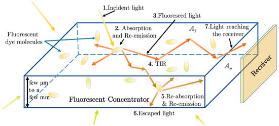
Figure 1.
Schematic depiction of a luminescent concentrator film. Ai and Ae denote the surface areas corresponding to light absorption and the output emission edge (where the receiver is located), respectively. The incident light (1) is absorbed and re-emitted (2) by the dye molecules inside the concentrator as fluorescence (3). Some of the light that remains within the critical angle of incidence at the surfaces undergoes total internal reflection (TIR) (4) and propagates within the concentrator. If there is an overlap between the absorption and emission spectra of the dye, some of this emitted light may be re-absorbed and may then be re-emitted (5). If it is not re-emitted, then this leads to re-absorption losses. The emitted light may also escape through the critical cone of the surfaces or edges of the concentrator, where there is no receiver/detector/solar cell. This light leakage leads to surface losses (6). The objective is to direct most (if not all) of the light to the receiver placed at the edges, which is designated as the useful concentrated light (7). It is important to note that surface losses occur whenever the emitted light falls within the critical cone angle of one of the surfaces. The thickness of such films that have been realized to date has ranged from a few µm to a few mm.
1.2. Liquid Crystals as Host Materials
Typically, the receiver is placed at one or more edges of the concentrator. The internal optical efficiency of a luminescent concentrator can then be defined as the ratio of the intensity of the fluorescence emission that reaches the detector to the intensity of the incident light [30].
To improve this ratio, the following conditions should be satisfied: firstly, the absorption of the light that is incident on the surface should be maximized, and the light that escapes through the film should be minimized. Secondly, the resulting fluorescence emission should be waveguided towards the edges by total internal reflection, with minimal losses through the surfaces. Surface loss is defined as the loss of light that escapes the critical cone of refraction through the surface of the film without being internally reflected [31].
One approach to achieving these conditions is to impart macroscopic directivity to the properties of absorption and emission in the films. This could be achieved by considering the use of dyes that have a more asymmetric molecular shape exhibiting a long molecular axis and combining these with a host material that provides macroscopic physical ordering to their absorption and emission transition dipole moments. This macroscopic ordering would lead to a preferred directivity in terms of absorption and emission, thereby enabling control over maximizing the absorption and re-directing the emission to reduce surface losses. The quality of the ordering, described quantitatively by a scalar order parameter, depends on both the anisotropy of the dye molecules and the order parameter of the host [32].
A host material that can impose a macroscopic orientational ordering on an asymmetric-shaped dye is a nematic LC, whose molecules align along a pseudo-unit vector known as the director [33,34,35]. Liquid crystals have been tremendously successful in flat-panel display technologies [36] and have been/are being considered for a broad range of alternative applications, including high-frequency technologies [37,38], biological systems [39], opto-electronic applications [40], communication engineering [41,42], and much more.
With nematic LC hosts, the dye guest–host effect described in Box 1 means that the transition dipole moments of the dye molecules also tend to align along this LC director [43]. The orientation of the director can be tuned using a range of external stimuli, which also enables the control of the anisotropy of the absorption by and emission from the luminescent film. LCs are therefore particularly interesting for luminescent concentrators because of the macroscopic ordering and their tuneable physical characteristics. In combination, these properties can serve to reduce the losses through the film.
Surface losses can also be reduced with the use of reflectors. For example, wavelength-selective reflectors external to the luminescent films can be employed: these transmit the incident wavelengths that need to be absorbed by the dyes but selectively reflect any light that is emitted by the dyes through fluorescence, which would otherwise escape from the film. Inorganic reflectors have been previously realized for luminescent concentrators for this purpose [44,45,46]. However, the relatively complex fabrication process means that there arises a need to devise a simpler way to realize a wavelength-selective reflector. To this end, the chiral nematic (alternatively known as cholesteric) mesophase has been employed to create thin-film organic reflectors. Chiral nematic LCs exhibit a director that forms a one-dimensional macroscopic helix with a length scale defined by the pitch (the distance over which the director rotates through a full 2π) [47]. This helical formation of the director provides a bandgap that gives rise to selective reflection, and the spectral location and width of this bandgap depend on the pitch of the helix, which can be tuned by adjusting the concentration of the chiral dopant [48]. This bandgap means that chiral nematic LC films can be used as wavelength-selective organic reflectors, therefore ensuring a further reduction in surface losses.
Box 1. The guest–host effect in liquid crystals.
The asymmetry in the molecular structures of organic dyes in terms of their length and breadth is represented by their aspect ratio and the presence of a long molecular axis. The higher the aspect ratio, the more asymmetric the structure, leading to a greater degree of anisotropy in the absorption and emission properties. In a nematic LC (a mesophase with long-range orientational order, but no positional order), the guest–host effect means that the long molecular axes of the dye molecules are typically distributed around the LC director n to form, on average, an angle of dye, as shown in Figure 2a. The absorption transition dipole moment aligns at an angle β to the long molecular axis. The absorbance depends on the cosine square of the angle between the absorption transition dipole moment and the polarization of the incident light [49]. Upon excitation, a dye molecule emits light as a radiating dipole, as shown in Figure 2b. The spatial intensity variation will follow the sine square of the angle that the propagation vector makes with the emission transition dipole moment [50]. The quality of the alignment of the absorption and emission transition dipole moments with the director is reflected in their respective order parameters. An order parameter (Sd) describes the overall ordering of the sample, and this also includes the effect of the ordering of the LC host itself. For a dichroic ratio D = A||/A, where A|| and A are, respectively, the values of absorbance for incident light parallel and perpendicular to the LC director, the order parameter can be defined as Sd = (D − 1)/(D + 2). The macroscopic director of a nematic LC host can be oriented along different directions, such as the planar (parallel to the substrates of the concentrator) and homeotropic (perpendicular to the substrates of the concentrator) alignments. Due to the guest–host effect, the transition dipole moments of the dye molecules can therefore also align along different directions determined by the orientation of the LC director. As a result, this represents an advantage in terms of control over the directivity of the absorbance and emission in such dye-doped LCs.

Figure 2.
(a) Reprinted with permission from [49]. The average pointing direction of the LC molecules is referred to as the director n, and the molecules locally orient at an angle of host relative to this pseudo-unit vector. In an LC host, the guest–host effect means that the long molecular axis of a dye aligns preferentially along the director n by being distributed at an angle of dye. The absorption transition dipole moment aligns along the director at an angle of β. The higher the asymmetry in the molecular structure, the smaller these angles, and thus, there will be a higher quality of alignment with the director n. (b) Reprinted from [50] with permission from AIP Publishing, New York, NY, United States. A fluorescent dye emitting photo-luminescence (PL) in both p and s polarizations as a radiating dipole.

1.3. Organization of This Review Article
Given the advantages of being able to create films with directive absorption and emission properties or with selective reflection properties, LCs have attracted considerable attention for use in luminescent concentrators. In light of this interest and the available body of literature, this paper comprehensively reviews the ways in which LCs have been implemented for use in luminescent concentrators. It presents the review by organizing the body of literature into three inter-related branches of research, as follows: First, we review reports that have investigated different alignments of the fluorophore using LCs. Second, we describe research that has focused on optimizing the chemical structures of the dye and approaches that have involved combining more than one dye in the concentrator. Third, the review also discusses the use of chiral nematic LCs as external reflective films for luminescent concentrators. Previous reviews have tended to focus more broadly on the topic of luminescent concentrators [22,23,24,26,27], whereas, in this paper, we consider in more depth the developments and understanding that are exclusive to LC concentrators.
This review is organized as follows. In Section 2, the review first summarizes the material combinations and techniques that have been investigated to realize the different LC-based luminescent concentrator films. Section 3 then discusses and presents a review of the first branch of research, which is carried out on the different LC alignments that have been considered (e.g., planar, homeotropic, hybrid), along with the accompanying analytical modelling of the effects that these alignments have on the absorption and fluorescence properties of the guest dyes. Section 4 then considers the second branch, which focuses on the research carried out to date on the development of dyes used in the films. Specifically, this section also reviews the work on different dye combinations linked by Förster resonance to improve light coupling when homeotropic alignments are used. This is followed by Section 5, which focuses on the third branch, namely, the implementation of chiral nematic LC reflectors. This section discusses the problem of the blueshift in the photonic bandgap for oblique incidences and the approaches that have been introduced to circumvent this issue. The conclusions, current technological limitations, and future perspectives are presented in the final section, Section 6.
2. Material Combinations and Characterization Techniques
A key list of the LC hosts, dyes, and other dopants (such as reactive mesogens and chiral dopants) used to realize LC luminescent concentrators is shown in Figure 3 pertaining to the discussion in Box 2. A commonly used LC host is the nematic LC mixture E7, where one of the components in the mixture is 5CB (Figure 3a). To realize a guest–host alignment inside the concentrator, the dyes most commonly studied have been Coumarins (Figure 3j), such as Coumarin-6 and K160, and perylene bisimides (for example, Figure 3h,i) because of their photostability, luminescence yield, and anisotropic molecular structures.
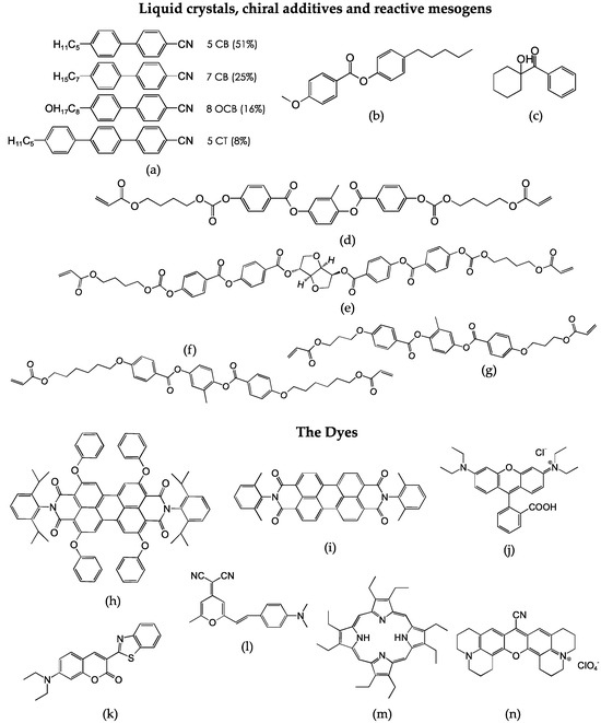
Figure 3.
Molecular structures of some of the different materials used in liquid-crystal (LC) concentrators. (a) Composition of the LC mixture, E7: 5CB: 4-Cyano-4′-N-pentylbiphenyl, 7CB: 4-Cyano-4′-N-heptylbiphenyl, 8OCB: 4-Cyano-4′-N-oxyoctylbiphenyl, 5CT: 4-Cyano-4″-N-pentyl-p-terphenyl (e.g., ref. [51]); (b) the Nematal 105 liquid crystal: 4-Pentylphenyl 4-methoxybenzoate (e.g., ref. [52]); (c) Irgacure 184 photoinitiator: 1-Hydroxy-cyclohexyl-phenyl-ketone (e.g., ref. [51]); (d) Paliocolor LC 242 liquid crystal: 4-[[[4-[(1-Oxo-2-propenyl)oxy]butoxy]carbonyl]oxy]benzoic acid 2-methyl-1,4-phenylene ester (e.g., ref. [53]); (e) LC 756, BASF chiral dopant: 1,4:3,6-dianhydro-D-glucitol bis[4-[[4-[[4-[(1-oxo-2-propenyl)oxy]butoxy]carbonyl]oxy]benzoyl]oxy]benzoate (e.g., ref. [54]); (f) the reactive mesogens RM82 (1,4-Di[4-(6-acryloyloxyhexyloxy)benzoyloxy]-2-methylbenzene) (e.g., ref. [51]) and (g) RM257 (2-methyl-1,4-phenylene bis(4-(3-(acroyloyloxy)propoxy)benzoate)) (e.g., ref. [51]); (h) Lumogen Red 305 dye: N,N′-Bis(2,6-diisopropylphenyl)-1,6,7,12-tetraphenoxy-3,4,9,10-perylenetetracarboxylic Diimide (e.g., ref. [55]); (i) PDI: N-N′-Bis(2,6-dimethylphenyl)pyrelene-3,4,9,10-tetracarboxylic Diimide (e.g., ref. [52]); (j) Coumarin 6: 3-(2-Benzothiazolyl)-7-(diethylamino)coumarin (e.g., ref. [56]); (k) DCM: (4-dicyanomethylene-2-methyl-6-(p-dimethylaminostyryl)-4H-pyran) (e.g., ref. [53]); (l) Rhodamine B: ([9-(2-carboxyphenyl)-6-diethylamino-3-xanthenylidene]-diethylammonium chloride) (e.g., ref. [51]); (m) porphyrin OEP: β-substituted octaethyl porphyrin (e.g., ref. [57]); (n) Rhodamine 800 (e.g., ref. [57]).
Box 2. Liquid-crystal hosts, chiral additives, reactive mesogens, and dyes used in luminescent concentrators reported in the literature.
The nematic LC mixture E7 + RM82/RM257 has been used as a host for dyes such as Rhodamine B, DCM, Red 305, Coumarin 6, and a derivative of Coumarin referred to as DFSB-K160 (respectively, Figure 3h,j–l). (Note: DFSB-K160 is a commercial product of Risk Reactor Inc., Santa Ana, California, United States, and its molecular structure is not published.) The 5CB LC has also been used as a host on its own for a Förster resonance pair comprising the OEP porphyrin (Figure 3m) and Rhodamine 800 (Figure 3n) dyes. The Nematal 105 LC (Figure 3b) has been used as a host for the PDI dye (a perylene-based dye) (Figure 3i), inducing a homeotropic alignment.
The dyes linked by Förster resonance are characterized as a donor and an acceptor. The donor (D)-and-acceptor (A) pairs for luminescent concentrator films have generally been PbS–quantum dots (D)–Coumarin-6 (A), Coumarin-6 (D)–Red 305 (A), and OEP-porphyrin (D)–Rhodamine (800) (A). Among these pairs, the donors have commonly been more isotropic in their chemical structures compared to their acceptor counterparts. LC756 has been used as a right-handed chiral dopant in E7 + RM82-based liquid-crystal polymer hosts to realize chiral nematic reflector films.
The structures of perylene bisimides have also been further optimized (discussed separately in Section 4). In addition, studies have considered locking in the LC alignment with photo-polymerizable reactive mesogens (RMs), for example, with RM82 or RM257 diacrylates (Figure 3f,g), in the presence of a photoinitiator (for example, Irgacure 184 in Figure 3c). Separately, for the chiral nematic mesophase, researchers have tended to opt for the LC756 chiral dopant (in the E7 + RM82 host), which is a right-handed chiral dopant (BASF) that has a helical twisting power of ≈+50 µm−1 (the exact value depends on the nematic host) (Figure 3e). The average thickness of the films that have been studied for luminescent solar concentrators has generally been in the range of 5–20 µm. Mixtures have typically been prepared by thermal diffusion at a temperature where the LC host is in the isotropic phase. In some cases, mixtures have been prepared in the presence of a solvent, such as toluene, with gentle stirring on a hot plate to improve the solubility of the dye in the LC host.
There have been two common techniques employed for the fabrication of LC-based luminescent concentrator films. One method involves first spin coating (typically around 1000 rpm for 15–30 s) a dye-doped LC solution onto a glass slide or a PMMA/Polycarbonate-based plate. The glass slide is typically coated apriori with a layer of surfactant (for example, Xylene or polyvinyl alcohol), and it is mechanically rubbed with a velvet cloth to induce a planar alignment. After spin coating, the samples are exposed to ultraviolet (UV) light in a nitrogen environment to form a cross-linked solid-dye-doped LC film. Another method involves the capillary filling of the dye-doped solution between glass substrates, separated by spacers and coated with a transparent conductive layer and/or a surfactant to trigger a macroscopic alignment of the LC director.
The technique favoured for the fabrication of chiral nematic reflectors has been to spin coat (using similar parameters to those mentioned above) and then UV crosslink a polymerizable chiral nematic LC on one/either side of a half-wave plate. Films created on either side of the half-wave plate result in polarization-independent reflectors, which will be discussed further in Section 5. Each side of the half-wave plate is coated with a surfactant and then mechanically rubbed to induce a planar alignment. To measure surface losses, a technique that is often employed is to illuminate the sample with a halogen lamp and to collect the emission using an integrating sphere (similar to the one shown in Figure 4c).

Figure 4.
Luminescent LC concentrators with planar alignment: (a) Reprinted with permission from [51] © John Wiley and Sons, New Jersey, United States. A schematic showing the difference in the intensity of emission at the edges of the concentrator, where emission is either perpendicular or parallel to the rubbing direction (the LC director alignment). (b) Reprinted with permission from [51] © John Wiley and Sons, United States. Integrated emission from an edge perpendicular (grey) or parallel (black) to the rubbing direction, in comparison to that of an isotropic concentrator (red), supported by least-squares fitting of the data. (c) Reprinted with permission from [51] © John Wiley and Sons, New Jersey, United States. The experimental arrangement for measuring the emission at the edges of an LC concentrator. (d) Reprinted with permission from [53] © The Optical Society, United States. A schematic of an energy-harvesting linear polarizer. Randomly polarized light is filtered by the dye-doped film so that the polarization parallel to the LC director is absorbed and directed to a photo-voltaic (PV) cell. The remaining portion of the incident beam passes through as a linearly polarized beam.
3. Liquid-Crystal Alignments
The idea of using LC hosts was initially proposed in ref. [58] with the key aims of reducing surface losses and improving the emission at the edges so as to improve the internal optical efficiency (defined as the ratio of light emitted to that absorbed). This has been achieved by aligning the transition dipole moment of the dye with the LC director, which is tuned so that the emission from the dyes at a macroscopic scale is coupled more towards the edges of the concentrator. Studies that have considered different alignments and the impact that they have on the performance of the luminescent concentrator will now be discussed in more detail in the following subsections.
3.1. Planar Alignments
A planar alignment of an E7 + RM82-based nematic LC host was demonstrated in [51]. Therein, a study was carried out on the role of anisotropy and the improvement in the edge emission in the concentrator for three different dyes, K160, DCM, and Rhodamine B, each having different orientational order parameters. As shown in the schematic in Figure 4a, there occurred a difference in the intensity of emission between orthogonal edges due to the alignment of the LC director. This was accompanied by a re-distribution of the emission along the edges. The authors determined the outputs from each edge and observed that (Figure 4b) the edge parallel to the rubbing direction/LC director (black-coloured data) showed a higher output than an edge that was oriented orthogonal to the LC director (grey-coloured data). It was also observed that the higher the anisotropy in the chemical structure of the dye (observed in Box 2), the higher the order parameter: Sd = 0.6 for K160 (compared to Sd = 0.05 for Rhodamine B, and Sd = 0.25 with DCM). It was also observed that by using dyes that are more anisotropic in nature, one can reduce the requirement for covering all four edges of the concentrator with photo-voltaic (PV) cells. Using an integrating sphere, the emission from the edge of the cell was determined (Figure 4c). In this work, the concentrators were 3–6 µm thick films that had been spin-coated and polymerized onto thick PMMA layers. For the K160 dye, which showed the highest orientational order parameter of the dye, Sd = 0.6, the authors reported a 30% improvement in the light output from the edge parallel to the director when compared to the emission recorded at any edge of another similar sample without the macroscopic LC alignment. This improvement of 30% was also the highest compared to the other two dyes having lower order parameters, which also meant that the higher the order parameter, the greater the anisotropy and the improvement in light emission.
Planar LC alignment was also studied in [53], where the concentrator was employed as an energy-harvesting polarizer that could be used in display devices. Here, the planar-aligned long molecular axes of the dye molecules preferentially absorb energy for a specific polarization whilst transmitting the remaining orthogonally polarized component through the concentrator. This resulting orthogonally polarized transmitted beam means that the luminescent concentrator effectively behaves as a linear polarizer (Figure 4d). This comes in addition to harvesting the energy of the absorbed polarization and directing the emission towards a PV, which is unlike a conventional polarizer where the energy is dissipated. For the purpose of demonstration, two example systems were considered (in a polymerizable liquid-crystal host): one with Coumarin-6 and another with a combination of two dyes, Coumarin-6 and DCM. The system with two dyes was considered as it also represents a concentrator that hosts two or more dye molecules that transfer energy in a cascade and harvest indoor radiation across the visible spectrum. The sample with only Coumarin-6 was measured to have an optical efficiency of 38% for light polarized parallel to the host director and 17% for light polarized perpendicular to the host director. For the system with a combination of dyes, optical efficiencies of 34% and 18% were measured, respectively, for light polarized parallel and perpendicular to the host director. These measurements of optical efficiency meant that the samples show anisotropy in harvesting light based on the polarization of incidence. The other polarization is not harvested but is allowed to pass through to enable the demonstration of a linear polarizer.
3.2. Homeotropic Alignments
While planar alignment has been used to demonstrate anisotropy in luminescent concentrators, homeotropic alignment has also attracted interest. The key benefit of this alignment configuration is that the emitted light is coupled more towards the edges of the concentrator rather than the surfaces, leading to an improvement in the internal optical efficiency of the concentrator. This benefit comes at the expense of a substantial reduction in the absorbance at normal incidence. The performance of the concentrator depends on the quality of the alignment of the dye (the order parameter) with the LC host, which is something that will be discussed further in Section 4; this section considers research carried out to optimize the chemical structures of dyes so as to ensure a larger orientational order parameter of the transition dipole moments of the dye. Alongside the quality of alignment, different methods have been used to achieve a homeotropic alignment, which can be categorized as either those that involve the application of a voltage across a planar-aligned LC cell (as in the initial studies [52,55]) or those that use surfactants [56,57].
The interest in the beginning was to experimentally establish what happens to the internal optical efficiency in the homeotropic alignment. One study [55] was performed where a concentrator was fabricated that was 20 µm thick and that was capillary-filled with a mixture of E7 and K160. The glass slides forming the concentrator were coated with transparent conductors and rubbed with polyimide surfactants to promote a planar alignment of the director in the absence of an applied voltage. By increasing the voltage across the concentrator, the LC alignment changed from a planar alignment towards a homeotropic alignment. During the investigation, two key observations were made. One, the absorbance and the edge emission of the concentrator were reduced. Two, the extent of the reduction in the edge emission was lower than that of the reduction in the absorbance. This meant that as the alignment changed to homeotropic with an increase in the voltage, there was an improvement in the internal efficiency of 25% (Figure 5a), along with a reduction in surface losses of 27%. An improvement in the optical efficiency despite a reduction in the absorbance became the key motivation for the further investigation of homeotropic alignments.
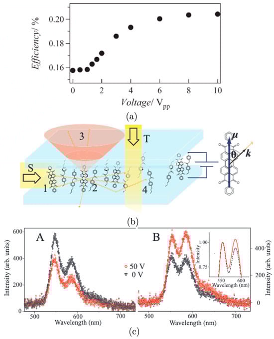
Figure 5.
Luminescent LC concentrators with homeotropic alignment: (a) Reprinted with permission from [55], © John Wiley and Sons, New Jersey, United States. The improvement in the internal efficiency with an increase in the bias voltage towards homeotropic alignment. (b) Reprinted with permission from [52] © The Optical Society, United States. A schematic depicting the different methods of excitation and the propagation of the resulting emission in the homeotropic alignment configuration. (c) Reprinted with permission from [52], © The Optical Society, United States. The emission spectra from the (A) top surface and (B) the narrow edge parallel to the beam excitation. Inset: Fitted emission spectra in (B) showing the effect of re-absorption shift upon homeotropic alignment.
A separate study was carried out to determine (theoretically) the efficiency of trapping the emitted fluorescence using homeotropic alignments [56]. The analytical results were presented for the trapping efficiency based on several assumptions. Specifically, it was assumed that a transition dipole aligned parallel to the long molecular axis determines the emission pattern and that the time-averaged power density of the emission could be characterized as that from a Hertzian dipole. These assumptions formed the basis of calculating different angles of dye inclination D with respect to the surface normal, which, for a waveguide and cladding refractive index nS and nC, respectively, was expressed as
For an air cladding and a waveguide refractive index of 1.7, it could be observed that the trapping efficiency increased from 73% for a planar LC alignment to 95% for a homeotropic alignment. Using a Coumarin-6-based concentrator (in an LC host—UCL018, Dai Nippon Ink and Chemicals Ltd., Tokyo, Japan) practically realized as a spin-coated and UV-cured thin film, the authors experimentally demonstrated that the homeotropic alignment provided a trapping efficiency of 81%, within the limits of imperfect dye alignment. However, there still remained the problem of weak absorbance with a homeotropically aligned dye, which leads to a low edge emission overall. One way to overcome this would be to use diffusers (external holographic diffusers) so that some part of the diffused incident light may have a polarization more aligned with the director and thus result in better absorbance. For this, the authors first performed experiments to characterize an improvement in the edge emission with an increasing angle of incident light from 0° to 55° to observe a monotonic increase in the normalized edge power of ≈45%. With the increasing strength of the diffuser, quantified in terms of the diffusion angle from 10° to 60°, the normalized edge power improved by ≈22%.
Another independent study was performed in [52], where the advantages of a homeotropic alignment in terms of improving the edge emission and reducing the surface emission were demonstrated by achieving excitation in a different way. It was argued that excitation (unpolarized Xenon lamp) from the top surface (T) (Figure 5b) does not give a clear picture of the effect of the homeotropic alignment compared to when the excitation is from one of the narrow edges (S) of the concentrator. For a homeotropic alignment, excitation from the top surface only helps observe a reduction in the surface emission. An improvement in the light coupling towards the edges with the homeotropic alignment cannot be demonstrated in this case because the absorbance from the top surface also decreases. An edge-based excitation, on the other hand, circumvents this problem of a reduction in absorbance (indicated as 1 in Figure 5b) and clearly demonstrates enhanced coupling (2) and a reduction in surface losses (3), with increased in-plane propagation (4). The effect of the application of the voltage across the film to demonstrate the effect that a homeotropic alignment has on the surface and the edge emission was observed, as shown in Figure 5c A and B, respectively. The surface emission is reduced by approximately a third, which is within the limitations of the alignment of the dye in the LC host. The emission from the edge of the concentrator was also shown to improve with a homeotropic alignment, something that was demonstrated for the first time. The authors of ref. [52], however, acknowledged that the homeotropic alignment alone is not sufficient to make an efficient concentrator. In their report, Macqueen et al. suggested using Förster resonance energy transfer (FRET), which was later demonstrated and is a subject that will be discussed further in Section 4.
3.3. Theoretical Modelling
The assumption of an isotropic emitter is generally employed when modelling the behaviour of luminescent concentrators. This assumption remains valid as long as the emitter is an isotropically emitting fluorophore and/or when the incident illumination is uniform from all directions. As mentioned in Box 2, the organic dyes considered in LC-based luminescent concentrators are not completely isotropic. The emission profile depends on both the dichroism of the dye and the angle of incidence of the sunlight relative to the concentrator. In reality, such emission profiles also further lead to successive re-absorption and re-emission, resulting in higher surface losses than those predicted with isotropic models. Therefore, to model the behaviour of an LC-based luminescent concentrator that contains dichroic dyes, it is important to incorporate these additional factors of dichroism and angular dependence into the concentrator simulations.
To this end, researchers have attempted to incorporate the dichroic nature of the dyes into simulation models that further enable one to predict the relationship between the fractional surface losses and the average number of re-absorption events in a concentrator. For isotropic ensembles of dichroic dyes, the model presented in ref. [59] involves the calculation of the fractional surface loss equated to a series sum of the trapping efficiencies after every re-emission event. The model was found to be in good agreement with previous experimental findings [51,55], for example, in terms of being able to predict the additional fractional surface losses, which could be attributed to the dependence of the emission profile and the subsequent degree of re-absorption on the direction of light incidence. In terms of understanding what factors are important in reducing surface losses, the model points towards reducing re-absorption-and-re-emission events by reducing the dye concentration.
A subsequent study [60] went a step further to include the nematic ordering and developed a formalism to describe aligned dye systems more generally. In this model, the authors assumed a guest–host distribution of the dye (μ) at a general tilt angle θ to the LC director along the z-axis, as shown in Figure 6 (left). They first used the Legendre polynomial (P2n)-based expansion [61,62] to express the distribution f(Ω) of the dye molecules around the director as
where S2n (no) represents the order parameters. These lead to a spatial light intensity distribution I, expressed as a function of two specific orders, S2,opt and S4,opt, as described in Ref. [63]. The resulting intensity distribution can be written as
where C1, C2, and C3 are coefficients. These coefficients C1, C2, and C3 are expressed as a function of the angles of light emission α and β and the incoming angle of light incidence ψ, as represented in Figure 6 (right). This formalism was analysed for the specific cases of planar and homeotropic alignments of the dye in a nematic LC host. The intensity of emission expressed in (4) enables the simulation and prediction of the resulting anisotropy in the emission at the edges of the concentrator. The dye order parameter (determined from the fluorescence measurements) was calculated and found to be Sd = 0.35, which was in close agreement with the values obtained experimentally (Sd = 0.37) in [51,56]. This agreement with experiments provides confidence in the model. However, it should be noted that the birefringence of the host and the effect of re-absorption were not considered in this model.
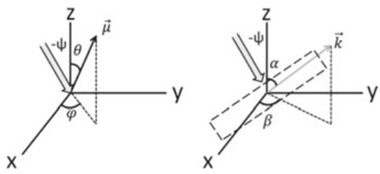
Figure 6.
Theoretical modelling: Reprinted with permission from [60]. The absorption (left) and emission (right) events are considered. A dipole µ is aligned at a vertical angle θ and an azimuthal angle φ. Incoming light is incident at an angle ψ with respect to the director of the dye ensemble. For the emission event, the emitted photon has a propagation vector k making a vertical angle α and azimuthal angle β.
3.4. Dye-Doped Chiral Nematic and Twisted Nematic Phases
The chiral nematic phase has also been considered as a means of reducing surface losses and improving the edge emission. The chiral nematic mesophase consists of a helical twist in the LC director such that this helical arrangement gives rise to a photonic bandgap in the transmission properties, with the pitch of the helix defining its central spectral position and the bandwidth (along with the refractive indices of the LC mixture) [47,48,64]. The pitch of the helix can be controlled by defining the concentration of the chiral dopant in the nematic host such that with higher concentrations, shorter pitches can be obtained. A higher concentration also means that the bandgap will be narrower and blue-shifted towards shorter wavelengths.
Researchers showed in [65] that the bandgap of the chiral nematic phase could be used to reduce surface losses by optimizing its spectral position. In this case, a 5CB-LC-based 10 µm thin film doped with a perylene dye and a cholesteryl oleyl carbonate (COC, Sigma-Aldrich, St. Louis, MO, United States)-based chiral dopant was fabricated. The solution was poured into a glass cell with planar alignment layers and then gradually cooled from the isotropic phase to form a uniform Grandjean alignment. Two cases were considered, where the bandgaps were located at different spectral positions. In the first case, A, the bandgap was co-located with the absorbance spectrum of the dye, with the central wavelength of the bandgap at 500 nm. In the second case, B, the bandgap was co-located with the emission spectrum of the dye, with the central wavelength at 690 nm.
A schematic illustrating what happens inside the concentrator for cases A and B is shown in Figure 7a (left) and (right), respectively. Compared to case A, the emission from the surface is more confined for case B, leading to a higher output emission from the collector edge. The spectral position of the bandgap was also analysed in terms of the effect of self-absorption. A beam with a 2 mm spot diameter was incident, and the distance between the excitation spot and the collector edge was varied. A spectrally bi-modal emission was recorded for both cases (Figure 7b (left) and (right)), with the weight distribution shifting from shorter to longer wavelengths for different excitation distances, accompanied by a decrease in the intensity. For a 9 millimolar (mM) dye concentration, this decrease in the intensity at the collector edge for case B when moving the spot from 2.5 mm to 10 mm was found to be only 46% (compared to 55% for case A), despite the larger self-absorption observed for case B (interpreted from the 23% re-distribution between the spectral peaks compared to only 15% for case A). It was speculated that in case B, the higher confinement of the emission overcomes the effect of the losses due to self-absorption. These observations lead to the conclusion that matching the bandgap to maximize the confinement of the emission from the dye (case B) was more advantageous than matching the bandgap to the absorbance spectrum of the dye (case A).

Figure 7.
Chiral nematic and twisted nematic phases. (a) Reprinted with permission from Taylor and Francis Ltd., London, England (http://www.tandfonline.com, last accessed: 30 September 2023.) [65]: schematic representations of a chiral-nematic-based concentrator: A (where the bandgap overlaps the absorbance spectrum of the dye) (left) and B (the bandgap overlaps the emission spectrum of the dye) (right). (b) Reprinted with permission from Taylor and Francis Ltd., London, England, (http://www.tandfonline.com, last accessed: 30 September 2023.) [65]: the bi-modal spectral emission intensities at the collector edge measured for different spot excitation distances, 2.5 mm, 5 mm, 7.5 mm, and 10 mm, for cases A (left) and B (right). (c) Reprinted with permission from [66] © John Wiley and Sons., New Jersey, United States. The absorbance (solid line) and emission (dashed line) spectra for a K160-dye-based concentrator with a concentration by weight of 3.4 wt% chiral dopant (red) and without chiral additives (black) for unpolarized excitation.
In addition to the macroscopic helical structures of chiral nematic LCs, super-twisted nematic LCs have also been considered. For example, in [66], the authors prepared a sample that consisted of the nematic E7 that was doped with the K160 dye and a left-handed low-twisting-power chiral dopant, S811. The concentration of the chiral dopant (3.4 wt%) was selected such that the director formed a super-twisted structure. When unpolarized light was incident on this luminescent concentrator, a higher portion of the incident light was absorbed by the cell when compared to a conventional dye-doped nematic LC cell. This occurs because the super-twist ensures that the light cannot follow the rotating LC director, resulting in all polarizations being available for absorption. With unpolarized light (Figure 7c), the authors observed a 28% improvement in the absorbance and an 11–15% improvement in the emission from the edge of the collector compared to a planar-aligned nematic concentrator. This improvement in the absorption comes at the expense of having equal emission at all four edges of the concentrator, therefore losing the benefits of anisotropy compared to the case of a planar-aligned nematic. In the same study, the authors also reported that by applying a voltage across the super-twisted nematic cell (28 Vrms for a 20 µm thick cell), the alignment changes to a conventional homeotropic nematic alignment, and the emission intensity decreases by 30%. However, the internal optical efficiency was higher (63%) than that observed for the super-twisted nematic case (48%).
3.5. Combining Positive and Negative Dichroism
Apart from the general aim of reducing surface losses with the LC alignment, an interesting use case of the combination of planar and homeotropic alignments of the transition dipoles of the dye was demonstrated in [67] for the purpose of advanced light management. For this study, a perylene dye (Red 305) was used, which was experimentally observed to have a negative dichroism in a nematic LC host. Therein, it was observed that there were two independent orthogonal transition dipoles, each exhibiting absorbance at two different wavelengths. One transition dipole aligned along the LC director and absorbed at λ = 445 nm, which exhibited positive dichroism, whereas the other aligned such that it was oriented orthogonal to the LC director and absorbed at λ = 584 nm, which exhibited negative dichroism. The intensity of emission from the edges of the concentrator was higher for the edges that were aligned perpendicular to the director compared to those that were aligned parallel to the director. This is because the absorption at 584 nm was higher than that observed at 445 nm. By combining this property of the perylene dye with a second dye (Coumarin 6) that showed positive dichroism, the colour and the intensity of light emitted from the orthogonal edges of the concentrator could be varied with different polarizations of incident light and applied voltages to the concentrator.
Illustrations of the concept of combining positive and negative dichroic dyes are shown in Figure 8a. For incident light with polarization that was parallel to the LC director, the absorbance due to the transition dipole of the Coumarin-6 dye was more enhanced, leading to a yellow appearance and preferential emission at the edge that was parallel to the LC director. However, for incident light polarized perpendicular to the director, a red-coloured appearance occurred with an emission that was preferentially towards the edge perpendicular to the director (because the absorbance due to the transition dipole of Red 305 was larger in this case). The appearance of the cells under different polarizations of incident light is shown in Figure 8b,d.
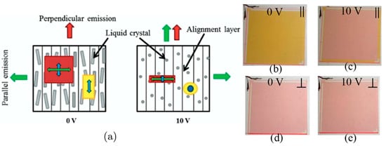
Figure 8.
Combining positive and negative dichroism. Reprinted with permission from [67], © John Wiley and Sons., New Jersey, United States. (a) Schematic representations of concentrators based on Red 305 (molecule represented by the red square box with the long axis shown as a green double-headed arrow; here, the molecule is aligned perpendicular to the LC director) and Coumarin-6 (molecule represented by the yellow rectangle with the long axis shown as a blue double-headed arrow; here, the long axis of the dye is aligned parallel to the LC director) under different applied voltages. The emission arrows roughly correspond to the colour of the light emitted from the edges. (b–e) The appearance of the concentrator for different polarizations of incident light (yellow for polarization parallel to the LC director, and red for polarization perpendicular to the LC director) and applied voltages (0 V and 10 V).
On the application of a voltage (10 V—towards homeotropic alignment), the appearance of the cell was observed to change for incident light with polarization parallel to the host director (Figure 8b,c), whereas, for a perpendicular-polarized incidence, the appearance did not change significantly (Figure 8d,e). The authors in [67] noted that this phenomenon observed for the combination of positive and negative dichroic dyes was potentially exciting for the development of colour-switchable windows (upon the application of voltage) while simultaneously having the ability to direct the emission from multi-dye systems to specific edges, enabling advanced light management.
4. Optimizing the Dye Structures and Combinations
The previous section has considered the various guest–host LC systems that have been investigated as a means to impart anisotropy to the absorbance and emission properties of a luminescent concentrator so as to improve the emission from the edges and/or reduce the surface losses. The alignment of the dye is mainly determined by a combination of the chemical structure of the dye, the orientational order of the LC host, and the interaction between the dye and the LC host [32,68,69]. In parallel with the studies described in the previous section, the research community has also considered how to improve the dyes themselves and/or the dye combinations to further enhance the alignment and the performance of these LC luminescent concentrators.
Perylene bisimides are, in general, characterized by good photostability, strong absorption anisotropy, and near-unity fluorescence yields [70,71] but a relatively low alignment (order parameters of 0.13–0.35). Research has been conducted to optimize the structures of perylene dyes [72,73,74] and the resulting behaviour in nematic LC hosts (e.g., E7). Figure 9a shows the structure of perylene bisimide 1, which consists of a single chromophore unit. The authors in [72] experimentally synthesized and studied the effect of increasing the number of chromophore units (2,3) on the order parameter in the LC host. In addition, they also investigated the role of a linker (4,5) in combining two chromophore units and its effect on the order parameter. They observed that as the number of units increased, the optical order parameter increased from 0.53 (1) to 0.80 (3) (the highest ever reported). However, this was accompanied by a redshift in the absorption peak of the dye (λ = 531 nm (1) to λ = 544 nm (3)), which means that a change in the properties of absorption occurs as the number of chromophore units increases. A tetramethylphenyl-based rigid linker (4) also improved the optical order parameter (0.73), but now with the advantage of introducing minimal changes to the absorption spectrum of the dye. A tetraheptyl-based rigid linker (5), however, formed a stack that resulted in crystallization and was not soluble in the LC host.
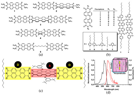
Figure 9.
Optimizing the chemical structures of perylene bisimide dyes. (a) Used with permission from the Royal Society of Chemistry, London, England, from [72]; permission conveyed through Copyright Clearance Center, Inc. The structures of perylenes 1–5 used in the study. (b) Reprinted with permission from [73] Copyright © 2014 American Chemical Society, Washington, United States (further permission related to the material should be directed to the ACS). A chart of the abbreviated molecular structures of fluorophores 1–8 synthesized in the study. (c) Reprinted with permission from [74] Copyright © 2014 American Chemical Society, Washington, United States (further permission related to the material should be directed to the ACS). Chemical structure of the triad perylene bisimide dye. (d) Reprinted with permission from [74] Copyright © 2014 American Chemical Society, Washington, United States (further permission related to the material should be directed to the ACS). Absorption (black) and emission (red) spectra of the triad-dye molecule, with excitation light polarized parallel (solid) and perpendicular (dashed) to the rubbing direction. For the emission spectra, the solid lines indicate that the measurement was obtained from edge 1, whereas the dashed line indicates that the measurement was obtained from edge 2. Inset: Illustration defining emission edges 1 and 2 relative to the rubbing direction.
Similar experimental studies have been carried out [73] to demonstrate the improvement in the order parameter and the solubility of perylene bisimides for use in LC luminescent concentrators. A systematic study was conducted that involved synthesizing various combinations of end-group substitutions R1 and R2 consisting of choices from A to E, making eight different combinations (1 to 8), as shown in Figure 9b.
It was observed that an increase in the number of ortho-isopropyl groups (1–6) steadily increased the solubility but at the expense of a slight reduction in the optical order parameter from 0.6 to 0.53. The addition of a fourth ortho-isopropyl group produced a large decrease in the solubility and the optical order parameter (to 0.22). The results indicate that dyes 3–6, which have asymmetric substitutions, have favourable core interactions, are highly soluble, and align well in an LC host.
Further progress in the dye structure [74] involved the development of a perylene bisimide triad, as shown in Figure 9c. The trimer was synthesized by joining a couple of perylene bisimides by a rigid linker on either side of a phenoxy-substituted perylene bisimide at the centre. By joining the perylenes with a rigid link, the optical order parameter can be increased to values as large as 0.8. A property of the triad was that the perylenes were also linked by Förster resonance [75], enabling the system to circumvent the effect of re-absorption losses. Evidence for the existence of a Förster resonance link was described with a comparison of the absorption and emission peaks of the individual chromophores and the triad. The perylenes at the two ends acted as donors, and the one at the centre acted as an acceptor. For the triad, the fluorescence spectrum revealed an emission peak at λ = 588 nm, the same as that of the acceptor, with no residual fluorescence of the donor, suggesting the near-unity efficiency of the energy transfer. In an LC host, as shown in Figure 9d, the rigid linker enabled the triad to exhibit a parallel-to-perpendicular edge emission ratio of 1.55, which was, at the time, the highest ever recorded.
As discussed in Section 3.2, homeotropic alignment, despite its advantages, leads to the reduced absorption of the incident light because of the orthogonal orientation of the preferential absorption axis of the dye molecules with respect to the incident polarization. In order to circumvent the problem of reduced absorption, alongside the progress in terms of optimizing the dye structures, research groups have also considered the use of a combination of two or more dyes that are linked by FRET [76]. FRET is a method of energy transfer that occurs via dipole–dipole interactions between two dyes, which are known as the donor and acceptor (similar to that described above for a single-dye system containing multiple chromophores) [77,78]. For an energy transfer to occur, the dye molecules should be situated within a critical distance, and there should be an overlap of the emission spectrum of the donor with that of the absorption spectrum of the acceptor. For the concentrators, the idea has been to use a donor dye that is more isotropic in nature so that it can absorb light from all directions/polarizations, while the acceptor dye is more anisotropic in nature so that it can align with the LC host and emit light preferentially towards the edges of the concentrator. In this way, the processes of absorption and emission would be decoupled between the two dyes to allow for the advantages of homeotropic alignment while circumventing the issue of reduced absorption.
One of the initial studies on this topic [57] presented a schematic summarizing the concept, as shown in Figure 10a. Therein, the authors proposed the use of the porphyrin OEP as the donor/absorber dye and Rhodamine-800 (R800) as the acceptor/emitter dye, with their respective emission and absorption spectra overlapping, as shown in Figure 10b. Concentrations of 5 mM of the OEP donor were doped with 60 mM of the R800 acceptor in a 5CB nematic LC host. The isotropic nature of the OEP dye meant that it avoided columnar formation in the nematic host, whereas the more anisotropic R800 dye aligned with the host. The OEP dye exhibited decoherence properties to avoid dipole selection upon absorption, which enabled it to absorb more isotropically and result in energy transfer to a nearby R800/acceptor/emitter that was aligned with the LC host in a homeotropic configuration. Concentrator samples with and without the OEP donor were prepared, and the alignment of the R800 molecules was confirmed experimentally by measuring the resulting fluorescence emission from the edge upon unpolarized excitation. The ratio of emission intensities polarized perpendicular and parallel to the substrate of the sample was used as the metric. For the sample with only R800, the homeotropically aligned molecules were preferentially excited and resulted in an intensity ratio of ≈0.67. However, for the sample with both OEP and R800, the OEP de-sensitized the excitation to improve the absorbance, which resulted in a fluorescence emission with a larger ratio of ≈2, which indicated the uniform excitation of R800 molecules by OEP molecules via FRET.

Figure 10.
FRET-based LC concentrators (with simulations). (a) Reprinted with permission from [57] Copyright © 2013 American Chemical Society, Washington, United States. The schematic of the proof-of-principle experiment for FRET (or simply RET: resonance energy transfer) in concentrators. (b) Reprinted with permission from [57] Copyright © 2013 American Chemical Society, Washington, United States. Absorbance and emission spectra of OEP and R800 molecules. (c) Reprinted from [79] with permission from AIP Publishing, New York, United States. Normalized optical efficiencies as a function of the distance between the dyes (blue) and the separation between the absorption peaks. (d) Reprinted from [79] with permission from AIP Publishing, New York, United States. Normalized optical efficiencies of the single-dye and FRET-based two-dye systems with respect to the geometrical gain. The relative improvement is also plotted.
The concept of FRET in concentrators [79] was considered further in a simulation-based model to investigate the effect of different properties on the optical efficiency. The authors in [79] considered a two-dye-based homeotropically aligned nematic LC concentrator. Some of the key metrics that were studied to observe the optical efficiency included the physical separation between the dyes, the separation between the absorption peaks, and the geometrical gain. To simulate the behaviour, a random mutation hill-climbing algorithm was used to optimize the optical efficiency while varying only one of these properties at a time. The results of the simulations are shown in Figure 10c,d. This study, based on simulations, implies that there is an optimal distance of separation between the dyes (≈1.5 nm) that is required to maximize the optical efficiency (≈9.4%). In their study, the authors suggested that this optimal separation occurs because, for shorter distances, there is a possibility of the energy being transferred back to the donor, whereas, for longer distances, the system decouples, preventing any FRET from taking place. For a given optimal distance of 1.5 nm, varying the separation between the absorption peaks revealed that for shorter separations (<100 nm), the internal optical efficiency was reduced (≈7.5%) due to energy being transferred back to the donor. For a larger separation (>200 nm), the energy transferred to the acceptor remained steady without much re-absorption, which, therefore, also made the optical efficiency remain constant (≈9.4%).
The effect of re-absorption becomes significant with the increasing geometrical gain of the concentrator. The optical efficiency, therefore, gradually decreases with the increasing geometrical gain, although it still demonstrates a relative improvement of ≈50% compared to a single-dye concentrator (within the simulation parameters considered in the work). Alongside these observations, it was also concluded that the optical efficiency improves when the donor-to-acceptor ratio increases (by ≈50%) and that quantum dots (for example, PbS) could be good candidates for use as the donor fluorophore, particularly for their isotropic properties in terms of the absorption of the incident light over a broad wavelength range (≈300 nm).
The importance of the physical shapes of the donor and the acceptor was experimentally studied in [80]. It was demonstrated that a more spherical-shaped dye would be preferred for the donor while having a rod-shaped dye as the acceptor. To this end, the authors in [80] synthesized diphenyl anthracene (DPA)-based derivatives combined with isopropyl substituents to realize different shapes of a donor dye (Figure 11a,c) to be used in conjunction with a homeotropically aligned rod-shaped Coumarin 6 acceptor. DPA derivatives were used because they are readily modifiable and have a high photo-luminescence efficiency and a good emission spectral overlap with the absorbance of Coumarin 6, as shown in Figure 11b. A study was initially conducted on the effect of the relative concentrations of the donor (Boron-DPA-1) to the Coumarin-6 acceptor. For a given concentration of the donor (50 mM), an increase in the concentration of Coumarin-6 from 4 mM to 8 mM resulted in an increase in the FRET efficiency from 75% to >92%. A Boron-DPA-1 (50 mM)/Coumarin-6 (8 mM) mixture was seen to be an optimal combination in terms of minimizing the re-absorption losses and therefore maximizing the optical efficiency of the concentration. The concentrations of the donor and acceptor influence the distance of separation between the dyes. So, these experimental observations are in accord with the findings of the simulations presented in [79], which predicted the presence of an optimal distance of separation in order to maximize the optical efficiency. For the Boron-DPA-1 derivative in conjunction with Coumarin 6 (having an overall Stokes’ shift of ≈75 nm), the resulting Förster-resonance-based system showed one of the best optical efficiencies of 78%.

Figure 11.
FRET-based LC concentrators (importance of physical shape). Reprinted with permission from [80] Copyright © 2019 American Chemical Society, Washington, United States. (a) The chemical structures of Coumarin-6 and the Boron(b)-DPA series. DPA: 9,10-Diphenylanthracene. (b) The normalized absorption (solid) and emission (dashed) spectra of Coumarin-6, DPA, bDPA-1, and bDPA-2. (c) Space-filling illustrations of the molecules from both the front and side views. The molecular shape changes from rod-like for Coumarin-6 to sphere-like for bDPA-2. Further details on the figure could be referred to in [80].
5. Chiral Nematic Reflectors
It was mentioned in Section 3.4 that chiral nematic LCs consist of a director that arranges into a macroscopic helix, such that the helical structure results in a bandgap in the transmission of light when the pitch is on the order of the wavelength of light. This bandgap acts only on the light whose polarization is of the same handedness as that of the helix. The pitch of the helix (along with the birefringence of the host) decides both the bandwidth and the spectral location of the transmittance bandgap, as described previously. Being able to control the characteristics of the bandgap makes chiral nematic LCs particularly attractive for thin-film reflectors. For incident light with an appropriate circular polarization and wavelength, a chiral nematic LC can act as an organic tuneable reflector. In the context of the luminescent concentrator, it could be used as a tuneable wavelength-selective reflector to reduce the losses from the front surface, as shown in the schematic in Figure 12a. For example, the chiral nematic reflector can exhibit a bandgap at a spectral location that could reflect the fluorescence emitted from the dye at the front surface (to prevent it from escaping) but, in parallel, allow external incident light to be received whose wavelength coincides with the absorption of the dye. This selective reflection property, as well as its tunability, is something that has attracted the interest of the luminescent concentrator community for more than a decade, with the primary aim of reducing surface losses. This section reviews the implementation and benefits of chiral nematic reflectors for use in luminescent concentrators.

Figure 12.
Chiral nematic reflector-based systems. (a) Reprinted from [54], with permission from AIP Publishing, New York, United States. The schematic of the luminescent solar concentrator (LSC) fitted with the wavelength-selective organic filter through which sunlight can pass, and the luminescence is reflected. (b) Transmission characteristics of white light (right-circularly polarized) through the chiral nematic reflector centred at ≈600 nm for incidence angles of 0°, 45°, and 85°. Created in the manuscript with simulations using Berreman’s 4 × 4 Matrix for chiral nematic liquid crystals. (c) Reprinted from [81] with permission from AIP Publishing, New York, United States. Transmission spectra (dashed: experimental; solid line: calculations) for normal-incidence unpolarized light of a right-handed chiral nematic stacked on a left-handed chiral nematic. The pitch varied from 437 nm to 520 nm in the right-handed material and from 429 nm to 521 nm in the left-handed material. The refractive indices, reported to be ne = 1.68 and no = 1.54, were the same for both chiral nematic LCs. (d) Reprinted from [81] with permission from AIP Publishing, New York, United States. Transmission spectra (dashed: experimental; solid line: calculations) for the normal-incidence unpolarized light of a stack of right-handed chiral nematics sandwiching a half-wave plate (centred at 825 nm). The pitch varied from 464 nm to 523 nm. The refractive indices for the material were reported to be ne = 1.68 and no = 1.54.
The idea of implementing a chiral nematic reflector was initially presented a few times at different conferences [82,83,84] before an initial set of experiments was published in [54]. The motivation for using a chiral nematic LC reflector came from its relative ease of tunability and fabrication compared to that of inorganic systems, which require the precise deposition of many layers of inorganic material, often under controlled vacuum conditions. In contrast, a chiral nematic reflector can be simply realized as a nematic LC doped with an appropriate concentration of the chiral dopant. As mentioned in Section 2, chiral nematic reflectors can be fabricated by using spin coating and UV crosslinking to form solid-polymer films (e.g., RM82 and RM257 doped into E7 with a chiral dopant such as LC756) on both sides of a pre-rubbed half-wave plate element. Using a half-wave plate and coating both sides of the reflector ensures that it functions for both types of handedness of circular polarization, given that a single layer of a chiral nematic can reflect only one handedness of the incident polarization.
Research on reducing surface losses with external reflectors or scatterers had been taking place [84,85,86,87] while chiral nematic reflectors were being introduced. For example, using a perylene dye in a polymer host, it was observed that the surface losses accounted for 65% of the light that was emitted when no reflector was used. However, upon the application of aluminium foils on all but the front surface, the surface losses could be reduced by up to 40%. Chiral nematic LC reflectors placed at the front of the concentrator were still deemed useful because such a large fraction of light escapes the concentrator from the front surface. A practical application [86] demonstrated a 35% reduction in surface losses and a 12% improvement in optical efficiency using a chiral nematic LC reflector positioned at the front surface. A comparison of the scatterers/mirrors used in conjunction with the reflector was also made, and it was concluded that a white scatterer (that re-randomizes the reflections towards the receiver PV at the edge) was better than a black absorber (because it absorbs the reflected light and negates the effect of the chiral nematic) or a perfect mirror (because it causes multiple reflections, leading to more re-absorption losses).
A chiral nematic reflector was observed to have a refractive index larger than the concentrator, which means that it is essential that an airgap be introduced between the reflector and the concentrator to prevent any waveguided light from escaping from the surface. Additionally, an airgap means that the chiral nematic could be re-used with other concentrator samples without being fixed to a single sample. Another important conclusion that has been considered is the importance of the effective size of the concentrator, where the larger the size of the concentrator, the greater the impact of the chiral nematic reflector when used in conjunction with a scatterer. This is because the light will be more effectively waveguided towards the edge by reflections between the chiral nematic and the scatterer.
To ensure that a chiral nematic reflector works effectively, the spectral location of the bandgap has to be carefully selected. This is because, for a chiral nematic LC, the spectral location of the bandgap seen by the incident light depends on the angle of incidence, as depicted in Figure 12b. Large angles of incidence result in a blueshift in the bandgap. For a luminescent concentrator, if the spectral location of the bandgap is such that its centre lies exactly on top of the emission peak of the dye, the bandgap will be observed to be blue-shifted for light escaping the surface of the concentrator at angles up to the critical angle and away from the surface normal. So, unless the spectral position and the bandwidth of the bandgap are appropriately determined, this blueshift in the bandgap might result in it not being able to cover the emission spectrum of the dye and therefore not enabling the chiral nematic LC to reflect the emission that would otherwise escape from the front surface. More importantly, a blueshift might also result in the bandgap covering the absorption spectrum of the dye, resulting in some of the incident light being reflected away from the concentrator that could have been absorbed by the dye. This problem was identified in [54,82,84], and it was suggested that it would be important to have a more redshifted and wider bandgap to compensate for this blueshift.
The redshift is desirable because it circumvents the potential problem of inadvertently covering the absorption spectrum, and the wider bandgap is beneficial because it avoids uncovering the emission spectrum of the dye at oblique angles of incidence. For example, for a dye emitting with a peak emission of λ = 600 nm, it was found that a centre wavelength of λ = 710 nm was useful [87]. A further experimental investigation was performed in [88], where chiral nematic reflectors with different bandgap locations at λ = 670 nm, 700 nm, 730 nm, 770 nm, and 810 nm were fabricated by simply varying the concentration of the chiral dopant. The authors observed that the farther the chiral nematic was located spectrally, the higher the edge emission was.
The problem of the blueshift in the bandgap at oblique incidence angles was the subject of further studies [81,88]. In particular, the importance of the bandwidth of the chiral nematic reflectors was considered further. In the first instance [81], it was demonstrated that the fabrication of a new chiral nematic reflector that had a broad bandwidth of about 100 nm and polarization-independent reflection properties was desirable. A broad bandwidth was realized practically by fabricating chiral nematic LC cells with a linear variation in the pitch through the application of a spatial gradient in the degree of polymerization. Polarization-independent behaviour was realized by making a stack of these reflectors in two different ways—firstly, as a left-handed chiral nematic on top of a right-handed chiral nematic, and secondly, as a stack of two right-handed chiral nematics with a half-wave plate in between. The transmittance spectra for normal incidence for films fabricated using these two different approaches are shown in Figure 12c,d. The results of these practical demonstrations showed that with broadband chiral nematic LCs, it is possible to reflect 97% of the incident unpolarized light, which is in good agreement with theoretical simulations.
The issue of the blueshift of the bandgap at oblique incidences was also further analysed in [88], where the authors compared experimental results with theoretical simulations. Berreman’s 4 × 4 matrix was used to simulate the reflection properties of different chiral nematic LCs, each exhibiting a different redshift and bandwidth, which were then compared with the results from experiments. For the simulations, it was concluded that the broadest reflector (400 nm), with its onset wavelength closest to the onset wavelength of the emission band, performs the best in terms of optical efficiency (up to 66%). However, it was observed that there were significant deviations when comparing the simulation results with experiments. This is considered to be due to the effect of re-absorption in the luminescent concentrator, which was not accounted for in the simulations. Moreover, this conclusion was further supported by the fact that a reflector with a shorter onset wavelength reflected wavelengths more in the tailed regions of the emission spectrum, which can be re-absorbed by the dye. This further implied that re-absorption in the concentrator indeed becomes the cause of the deviation between the experimental results and the predictions made with simulations on the performance of a chiral nematic reflector for use in conjunction with the concentrator.
A key problem that arises due to the blueshift at oblique incidence is the possibility of the absorbance spectrum being covered by the bandgap of the reflector. This results in the incident light (for wavelengths that could be absorbed by the dye) being reflected away from the concentrator. To address this issue, studies have been conducted [89] that have proposed the use of LC compounds that exhibit significant dispersion in the refractive indices across visible wavelengths. These have been labelled as special dispersion LCs. Generally, the refractive index varies as a function of the wavelength λ, as described by Cauchy’s equation,
where no is the null refractive index, and B1 is a real coefficient. With a special dispersion LC, if the coefficient B1 is such that the difference between the ordinary and extraordinary refractive indices becomes almost zero over a certain range of wavelengths, one can create a chiral nematic whose bandgap also vanishes over the given spectral range. These special dispersion chiral nematics could be useful as reflectors because, in the event of a blueshift in the bandgap, a special dispersion LC with a certain B1 could be chosen so that the blue-shifted bandgap vanishes over the spectral range where the absorption spectrum of the dye also exists. This effectively overcomes the effect of the blue-shifted bandgap covering the absorption spectrum of the dye.
The authors in [89] performed a simulation of a hypothetical special dispersion chiral nematic to realize broad reflection bands of 75 nm, 175 nm, and 400 nm. Berreman’s 4 × 4 matrix was then used to analyse the blueshift while varying the coefficients B1 and no to reduce the birefringence to zero at the desired wavelength range. Simulations were conducted to realize a bandgap that disappeared at three different spectral locations of 575 nm, 600 nm, and 625 nm, and it was concluded that the efficiency improved if the bandgap was located at a shorter wavelength (λ = 575 nm) and if the bandwidth was sufficiently broad (400 nm). These simulations, however, have not yet been supported by experimental results. Experimental validation might require one to choose an appropriate special dispersion LC (having a suitable coefficient B1) based on the dye that will be incorporated into the concentrator.
6. Conclusions and Further Discussion
As the research conducted to date has highlighted, liquid crystals (LCs) are very promising for luminescent solar concentrators, particularly as they can improve the internal optical efficiency and reduce surface losses. Both nematic and chiral nematic LCs have been considered as hosts, along with a range of different alignment configurations. In addition, the chiral nematic phase has also been used to create wavelength-selective reflectors that can be placed external to the luminescent concentrator.
The homeotropic alignment of the host (and, therefore, the transition dipole moment of the dye) has been preferred for its advantages of coupling the emission towards the edges while simultaneously reducing surface losses. New chemical structures in the form of perylene dyes have been synthesized to improve the dye order parameters, with some of the most promising exhibiting order parameters as high as 0.8 with internal optical efficiencies of 66% [74]. The disadvantage of reduced absorbance that comes with a homeotropic alignment has been addressed by using a combination of two dyes linked by Förster resonance—wherein a more isotropic donor absorbs the light isotropically to couple it non-radiatively to a more anisotropic acceptor whose transition dipole moment is aligned with the LC director (homeotropic alignment). Encouragingly, one of the latest studies [80] that have implemented FRET has achieved an improvement in the internal optical efficiency of 78%. Such studies have also been supported with simulation models.
Based upon the previous research carried out to date, it would seem that the preferred configuration in terms of the current state of the art for the LC luminescent solar concentrator depends on the choice of the alignment of the host, the dye, and the external reflector. The authors believe the best alignment could be homeotropic, combined with a dye having a relatively large order parameter in a suitable LC host coupled to an isotropic donor via the Förster resonance link to circumvent any reduced absorbance, as also summarized by the discussions of the latest published review article in Ref. [78].
Something that has not been considered in this review is the body of research dedicated to smart windows, which is an additional functionality that could be incorporated into the concentrator. This research topic has progressed in parallel with the development of LC luminescent concentrators [27,66,90]. Smart windows are devices that can change their transparency/colour based on the alignment of the LC for dye guest–host systems. The LC luminescent concentrator can also act as a dye-doped LC switchable window that would provide both an energy-harvesting capability and an aesthetically pleasing appearance. In the same vein, polymer-dispersed liquid crystals (PDLCs) have also been useful as scatterers for luminescent concentrators to reduce any surface losses from the rear surface [91,92]. The voltage tuneable property of the LCs, however, was more useful for the application of a smart window, rather than a concentrator. So, being beyond the scope of this review, their application has been excluded from the survey.
Further research on LC luminescent concentrators should be targeted to overcome the existing limitations and the possible advances that could be made in this regard. Modelling LC luminescent concentrators is essential, particularly the effect of re-absorption in such systems, without which one cannot precisely model the effect of the alignment. It would be desirable if theoretical modelling could be developed further to include the effect of re-absorption, which has been accounted for previously in models for conventional luminescent concentrators without the use of LCs, as, for example, in [93,94]. Further research on the effect of LC ordering on the optical concentration and optical efficiency would be beneficial. Similarly, other LC phases, for example, the smectic phase and blue phases [95,96], might also be worthy of investigation. In the former case, the LC would provide both orientational and positional ordering to the transition dipoles of the dyes, which may well be advantageous in terms of the optical efficiency. For chiral nematic reflectors, a further step to circumvent the issue of the blueshift at oblique angles might be to consider the use of chiral nematic particles [97,98]. Finally, the use of special dispersion LCs, as proposed in [89], could be experimentally investigated.
This review primarily focuses on the application of LCs for luminescent concentrators useful for solar energy harvesting. However, there are other applications of the luminescent concentrator, as outlined in [28]. The advantage of the alignment of the LCs for luminescent concentrators involved in these other applications has not been considered in any great detail as of yet. For some of these alternative applications, it is possible that the requirements in terms of the alignment of the host and the choice of dye (or dye combinations) could be different from those needed for solar energy harvesting. One of the key examples would be the use of LC luminescent concentrators in optical wireless communication/LiFi links [99,100,101]. Luminescent concentrators for optical wireless links have gained interest over the past decade, with theoretical simulations [102,103] and experimental demonstrations [104,105,106,107,108] on different configurations and data-multiplexing-based applications. The first demonstration of the use of an LC luminescent concentrator with planar alignments of the dye as a polarization-sensitive antenna for optical wireless links was also recently published [109]. Further research needs to be conducted on whether advanced configurations, such as the homeotropic alignment supported by Förster-resonance-linked dye combinations, may be useful. The authors speculate that Förster-resonance-based systems having two or more dyes could limit the achievable bandwidth of an optical wireless link, because a single dye itself presents this challenge [110,111,112,113]. These speculations, however, need to be supported by experimental evidence, which therefore opens up broad possibilities for further research on LCs for luminescent concentrators.
Author Contributions
A.S. performed the extensive survey of literature and wrote the entire firstdraft of the manuscript. This was followed by the contributions of G.Z., R.S., G.F., D.C.O. and M.J.B., in the revised versions. The manuscript was supervised and edited overall by S.M.M. All authors have read and agreed to the published version of the manuscript.
Funding
This manuscript was written when A.S. was pursuing his Ph.D. (D.Phil.) at Oxford as a Commonwealth scholar funded by the U.K. government. He is a member of Wadham College, Oxford. This research was funded by the Commonwealth Scholarship Commission with the grant number INCS-2019-227. The APC was funded by the University of Oxford, U.K.
Data Availability Statement
Not applicable.
Acknowledgments
The authors kindly acknowledge the Department of Engineering Science, University of Oxford, and the Bodleian Libraries accessible from Wadham College, University of Oxford, for the resources provided to perform the extensive survey of the literature.
Conflicts of Interest
The authors declare no conflict of interest.
References
- Smets, A.H.M.; Jäger, K.; Isabella, O.; van Swaaij, R.A.; Zeman, M. Solar Energy: The Physics and Engineering of Photovoltaic Conversion, Technologies and Systems, 1st ed.; UIT Cambridge Ltd.: Cambridge, UK, 2016; Volume 1, ISBN 978 1 906860 32 5. [Google Scholar]
- Boxwell, M. Solar Electricity Handbook: 2017 Edition: A Simple, Practical Guide to Solar Energy—Designing and Installing Solar Photovoltaic Systems. (The Solar... and Installing Solar Photovoltaic Systems), 11th ed.; Greenstream Publishing Limited: Birmingham, UK, 2017; Volume 1. [Google Scholar]
- Winston, R. Dielectric Compound Parabolic Concentrators. Appl. Opt. 1976, 15, 291–292. [Google Scholar] [CrossRef]
- Winston, R.; Hinterberger, H. Principles of Cylindrical Concentrators for Solar Energy. Sol. Energy 1975, 17, 255–258. [Google Scholar] [CrossRef]
- Coffey, V.C. Solar Concentrators: Using Optics to Boost Photovoltaics. Opt. Photonics News 2011, 22, 22–27. [Google Scholar] [CrossRef]
- Zacharopoulos, A.; Eames, P.C.; McLarnon, D.; Norton, B. Linear Dielectric Non-Imaging Concentrating Covers for PV Integrated Building Facades. Sol. Energy 2000, 68, 439–452. [Google Scholar] [CrossRef]
- Apostoleris, H.; Stefancich, M.; Chiesa, M. Tracking-Integrated Systems for Concentrating Photovoltaics. Nat. Energy 2016, 1, 16018. [Google Scholar] [CrossRef]
- Madala, S.; Boehm, R.F. A Review of Nonimaging Solar Concentrators for Stationary and Passive Tracking Applications. Renew. Sustain. Energy Rev. 2017, 71, 309–322. [Google Scholar] [CrossRef]
- Winston, R. Principles of Solar Concentrators of a Novel Design. Sol. Energy 1974, 16, 89–95. [Google Scholar] [CrossRef]
- Lim, Y.S.; Lo, C.K.; Kee, S.Y.; Ewe, H.T.; Faidz, A.R. Design and Evaluation of Passive Concentrator and Reflector Systems for Bifacial Solar Panel on a Highly Cloudy Region—A Case Study in Malaysia. Renew. Energy 2014, 63, 415–425. [Google Scholar] [CrossRef]
- Batchelder, J.S.; Zewai, A.H.; Cole, T. Luminescent Solar Concentrators 1: Theory of Operation and Techniques for Performance Evaluation. Appl. Opt. 1979, 18, 3090–3110. [Google Scholar] [CrossRef]
- Weber, W.H.; Lambe, J. Luminescent Greenhouse Collector for Solar Radiation. Appl. Opt. 1976, 15, 2299–2300. [Google Scholar] [CrossRef]
- Levitt, J.A.; Weber, W.H. Materials for Luminescent Greenhouse Solar Collectors. Appl. Opt. 1977, 16, 2684–2689. [Google Scholar] [CrossRef]
- Goetzberger, A.; Greube, W. Solar Energy Conversion with Fluorescent Collectors. Appl. Phys. 1977, 14, 123–139. [Google Scholar] [CrossRef]
- Swartz, B.A.; Cole, T.; Zewail, A.H. Photon Trapping and Energy Transfer in Multiple-Dye Plastic Matrices: An Efficient Solar-Energy Concentrator. Opt. Lett. 1977, 1, 73–75. [Google Scholar] [CrossRef]
- Hermann, A.M. Luminescent Solar Concentrators—A Review. Sol. Energy 1982, 29, 323–329. [Google Scholar] [CrossRef]
- Barnham, K.; Marques, J.L.; Hassard, J.; O’Brien, P. Quantum-Dot Concentrator and Thermodynamic Model for the Global Redshift. Appl. Phys. Lett. 2000, 76, 1197–1199. [Google Scholar] [CrossRef]
- Baumberg, I.; Berezin, O.; Drabkin, A.; Gorelik, B.; Kogan, L.; Voskobojnik, M.; Zaidman, M. Effect of Polymer Matrix on Photo-Stability of Photo-Luminescent Dyes in Multi-Layer Polymeric Structures. Polym. Degrad. Stab. 2001, 73, 403–410. [Google Scholar] [CrossRef]
- Rau, U.; Einsele, F.; Glaeser, G.C. Efficiency Limits of Photovoltaic Fluorescent Collectors. Appl. Phys. Lett. 2005, 87, 171101. [Google Scholar] [CrossRef]
- Earp, A.A.; Smith, G.B.; Swift, P.D.; Franklin, J. Maximising the Light Output of a Luminescent Solar Concentrator. Sol. Energy 2004, 76, 655–667. [Google Scholar] [CrossRef]
- Chatten, A.J.; Barnham, K.W.J.; Buxton, B.F.; Ekins-Daukes, N.J.; Malik, M.A. Quantum Dot Solar Concentrators. Semiconductors 2004, 38, 909–917. [Google Scholar] [CrossRef]
- Rowan, B.C.; Wilson, L.R.; Richards, B.S. Advanced Material Concepts for Luminescent Solar Concentrators. IEEE J. Sel. Top. Quantum Electron. 2008, 14, 1312–1322. [Google Scholar] [CrossRef]
- van Sark, W.G.J.H.M.; Barnham, K.W.J.; Slooff, L.H.; Chatten, A.J.; Büchtemann, A.; Meyer, A.; McCormack, S.J.; Koole, R.; Farrell, D.J.; Bose, R.; et al. Luminescent Solar Concentrators—A Review of Recent Results. Opt. Express 2008, 16, 21773–21792. [Google Scholar] [CrossRef]
- Debije, M.G.; Verbunt, P.P.C. Thirty Years of Luminescent Solar Concentrator Research: Solar Energy for the Built Environment. Adv. Energy Mater. 2012, 2, 12–35. [Google Scholar] [CrossRef]
- Corrado, C.; Leow, S.W.; Osborn, M.; Carbone, I.; Hellier, K.; Short, M.; Alers, G.; Carter, S.A. Power Generation Study of Luminescent Solar Concentrator Greenhouse. J. Renew. Sustain. Energy 2016, 8, 043502. [Google Scholar] [CrossRef]
- Griffini, G. Host Matrix Materials for Luminescent Solar Concentrators: Recent Achievements and Forthcoming Challenges. Front. Mater. 2019, 6, 1–8. [Google Scholar] [CrossRef]
- Frias, A.R.; Correia, S.F.H.; Martins, M.; Ventura, S.P.M.; Pecoraro, E.; Ribeiro, S.J.L.; André, P.S.; Ferreira, R.A.S.; Coutinho, J.A.P.; Carlos, L.D. Sustainable Liquid Luminescent Solar Concentrators. Adv. Sustain. Syst. 2019, 3, 1800134. [Google Scholar] [CrossRef]
- Papakonstantinou, I.; Portnoi, M.; Debije, M.G. The Hidden Potential of Luminescent Solar Concentrators. Adv. Energy Mater. 2021, 11, 2002883. [Google Scholar] [CrossRef]
- Castelletto, S.; Boretti, A. Luminescence Solar Concentrators: A Technology Update. Nano Energy 2023, 109, 108269. [Google Scholar] [CrossRef]
- Tummeltshammer, C.; Taylor, A.; Kenyon, A.J.; Papakonstantinou, I. Losses in Luminescent Solar Concentrators Unveiled. Sol. Energy Mater. Sol. Cells 2016, 144, 40–47. [Google Scholar] [CrossRef]
- Oliveto, V.J.; Boyd, C.; Smith, D.; Hughes, M.; Borca-Tasciuc, D.-A. Luminescent Solar Concentrators: A Review of Nanoengineering Opportunities for Reducing Surface Losses. IEEE Trans. Nanotechnol. 2022, 21, 360–366. [Google Scholar] [CrossRef]
- Pålsson, L.-O.; Vaughan, H.L.; Smith, A.; Szablewski, M.; Cross, G.H.; Roberts, T.; Masutani, A.; Yasuda, A.; Beeby, A.; Bloor, D. Guest–Host Interactions between Dichroic Dyes and Anisotropic Hosts. J. Lumin. 2006, 117, 113–122. [Google Scholar] [CrossRef]
- Stephen, M.J.; Straley, J.P. Physics of Liquid Crystals. Rev. Mod. Phys. 1974, 46, 617–704. [Google Scholar] [CrossRef]
- Andrienko, D. Introduction to Liquid Crystals. J. Mol. Liq. 2018, 267, 520–541. [Google Scholar] [CrossRef]
- Priestley, E.B. Liquid Crystal Mesophases. In Introduction to Liquid Crystals; Springer: Boston, MA, USA, 1975; pp. 1–13. [Google Scholar]
- Hahm, S.G.; Ko, Y.-G.; Rho, Y.; Ahn, B.; Ree, M. Liquid Crystal Alignment in Advanced Flat-Panel Liquid Crystal Displays. Curr. Opin. Chem. Eng. 2013, 2, 71–78. [Google Scholar] [CrossRef]
- Kowerdziej, R.; Parka, J.; Krupka, J.; Olifierczuk, M.; Nowinowski-Kruszelnicki, E.; Jaroszewicz, L.; Chojnowska, O. Dielectric Properties of Highly Anisotropic Nematic Liquid Crystals for Tunable Microwave Components. Appl. Phys. Lett. 2013, 103, 172902. [Google Scholar] [CrossRef]
- Zografopoulos, D.C.; Ferraro, A.; Beccherelli, R. Liquid-Crystal High-Frequency Microwave Technology: Materials and Characterization. Adv. Mater. Technol. 2019, 4, 1800447. [Google Scholar] [CrossRef]
- Lowe, A.M.; Abbott, N.L. Liquid Crystalline Materials for Biological Applications. Chem. Mater. 2012, 24, 746–758. [Google Scholar] [CrossRef]
- Kaafarani, B.R. Discotic Liquid Crystals for Opto-Electronic Applications. Chem. Mater. 2011, 23, 378–396. [Google Scholar] [CrossRef]
- Ma, J.; Choi, J.; Park, S.; Kong, I.; Kim, D.; Lee, C.; Youn, Y.; Hwang, M.; Oh, S.; Hong, W.; et al. Liquid Crystals for Advanced Smart Devices with Microwave and Millimeter-Wave Applications: Recent Progress for Next-Generation Communications. Adv. Mater. 2023, 35, 2302474. [Google Scholar] [CrossRef]
- Zou, J.; Yang, Z.; Mao, C.; Wu, S.-T. Fast-Response Liquid Crystals for 6G Optical Communications. Crystals 2021, 11, 797. [Google Scholar] [CrossRef]
- Heilmeier, G.H.; Zanoni, L.A. Guest-host interactions in nematic liquid crystals. A new electro-optic effect. Appl. Phys. Lett. 1968, 13, 91–92. [Google Scholar] [CrossRef]
- Goldschmidt, J.C.; Peters, M.; Bösch, A.; Helmers, H.; Dimroth, F.; Glunz, S.W.; Willeke, G. Increasing the Efficiency of Fluorescent Concentrator Systems. Sol. Energy Mater. Sol. Cells 2009, 93, 176–182. [Google Scholar] [CrossRef]
- Goldschmidt, J.C.; Peters, M.; Prönneke, L.; Steidl, L.; Zentel, R.; Bläsi, B.; Gombert, A.; Glunz, S.; Willeke, G.; Rau, U. Theoretical and Experimental Analysis of Photonic Structures for Fluorescent Concentrators with Increased Efficiencies. Phys. Status Solidi (a) 2008, 205, 2811–2821. [Google Scholar] [CrossRef]
- Portnoi, M.; Macdonald, T.J.; Sol, C.; Robbins, T.S.; Li, T.; Schläfer, J.; Guldin, S.; Parkin, I.P.; Papakonstantinou, I. All-Silicone-Based Distributed Bragg Reflectors for Efficient Flexible Luminescent Solar Concentrators. Nano Energy 2020, 70, 104507. [Google Scholar] [CrossRef]
- Coates, D. Development and Applications of Cholesteric Liquid Crystals. Liq. Cryst. 2015, 42, 653–665. [Google Scholar] [CrossRef]
- Taugerbeck, A.; Booth, C.J. Design and Synthesis of Chiral Nematic Liquid Crystals. In Handbook of Liquid Crystals; Wiley-VCH Verlag GmbH & Co. KGaA: Weinheim, Germany, 2014; pp. 1–63. [Google Scholar]
- Sims, M.T. Dyes as Guests in Ordered Systems: Current Understanding and Future Directions. Liq. Cryst. 2016, 43, 2363–2374. [Google Scholar] [CrossRef]
- Fujieda, I.; Suzuki, D.; Masuda, T. Tilted Dipole Model for Bias-Dependent Photoluminescence Pattern. J. Appl. Phys. 2014, 116, 224507. [Google Scholar] [CrossRef]
- Verbunt, P.P.C.; Kaiser, A.; Hermans, K.; Bastiaansen, C.W.M.; Broer, D.J.; Debije, M.G. Controlling Light Emission in Luminescent Solar Concentrators Through Use of Dye Molecules Aligned in a Planar Manner by Liquid Crystals. Adv. Funct. Mater. 2009, 19, 2714–2719. [Google Scholar] [CrossRef]
- MacQueen, R.W.; Cheng, Y.Y.; Clady, R.G.C.R.; Schmidt, T.W. Towards an Aligned Luminophore Solar Concentrator. Opt. Express 2010, 18, A161. [Google Scholar] [CrossRef]
- Mulder, C.L.; Reusswig, P.D.; Beyler, A.P.; Kim, H.; Rotschild, C.; Baldo, M.A. Dye Alignment in Luminescent Solar Concentrators: II Horizontal Alignment for Energy Harvesting in Linear Polarizers. Opt. Express 2010, 18, A91. [Google Scholar] [CrossRef]
- Debije, M.G.; Van, M.-P.; Verbunt, P.P.C.; Kastelijn, M.J.; van der Blom, R.H.L.; Broer, D.J.; Bastiaansen, C.W.M. Effect on the Output of a Luminescent Solar Concentrator on Application of Organic Wavelength-Selective Mirrors. Appl. Opt. 2010, 49, 745–751. [Google Scholar] [CrossRef]
- Debije, M.G. Solar Energy Collectors with Tunable Transmission. Adv. Funct. Mater. 2010, 20, 1498–1502. [Google Scholar] [CrossRef]
- Mulder, C.L.; Reusswig, P.D.; Velázquez, A.M.; Kim, H.; Rotschild, C.; Baldo, M.A. Dye Alignment in Luminescent Solar Concentrators: I Vertical Alignment for Improved Waveguide Coupling. Opt. Express 2010, 18, A79. [Google Scholar] [CrossRef]
- MacQueen, R.W.; Schmidt, T.W. Molecular Polarization Switching for Improved Light Coupling in Luminescent Solar Concentrators. J. Phys. Chem. Lett. 2013, 4, 2874–2879. [Google Scholar] [CrossRef]
- Debije, M.G.; Verbunt, P.P.C.; Rowan, B.C.; Richards, B.S.; Hoeks, T.L. Measured Surface Loss from Luminescent Solar Concentrator Waveguides. Appl. Opt. 2008, 47, 6763–6768. [Google Scholar] [CrossRef]
- Verbunt, P.P.C.; Sánchez-Somolinos, C.; Broer, D.J.; Debije, M.G. Anisotropic Light Emissions in Luminescent Solar Concentrators–Isotropic Systems. Opt. Express 2013, 21, A485. [Google Scholar] [CrossRef]
- Verbunt, P.P.C.; de Jong, T.M.; de Boer, D.K.G.; Broer, D.J.; Debije, M.G. Anisotropic Light Emission from Aligned Luminophores. Eur. Phys. J. Appl. Phys. 2014, 67, 10201. [Google Scholar] [CrossRef]
- Bauman, D.; Moryson, H.; Wolarz, E. Orientational Behaviour of the Guest-Host Systems in the Smectic A and Nematic Phases. Acta Phys. Pol. A 1992, 81, 559–570. [Google Scholar] [CrossRef]
- Zannoni, C. Order Parameters and Orientational Distributions in Liquid Crystals. In Polarized Spectroscopy of Ordered Systems; Springer: Dordrecht, The Netherlands, 1988; pp. 57–83. [Google Scholar]
- van Ewyk, R.L.; O’Connor, I.; Mosley, A.; Cuddy, A.; Hilsum, C.; Blackburn, C.; Griffiths, J.; Jones, F. Anisotropic Fluorophors for Liquid Crystal Displays. Displays 1986, 7, 155–160. [Google Scholar] [CrossRef]
- Mulder, D.J.; Schenning, A.P.H.J.; Bastiaansen, C.W.M. Chiral-Nematic Liquid Crystals as One Dimensional Photonic Materials in Optical Sensors. J. Mater. Chem. C 2014, 2, 6695–6705. [Google Scholar] [CrossRef]
- Rodarte, A.L.; Cisneros, F.; Hirst, L.S.; Ghosh, S. Dye-Integrated Cholesteric Photonic Luminescent Solar Concentrator. Liq. Cryst. 2014, 41, 1442–1447. [Google Scholar] [CrossRef][Green Version]
- Sol, J.A.H.P.; Timmermans, G.H.; Breugel, A.J.; Schenning, A.P.H.J.; Debije, M.G. Multistate Luminescent Solar Concentrator “Smart” Windows. Adv. Energy Mater. 2018, 8, 1702922. [Google Scholar] [CrossRef]
- Debije, M.G.; Menelaou, C.; Herz, L.M.; Schenning, A.P.H.J. Combining Positive and Negative Dichroic Fluorophores for Advanced Light Management in Luminescent Solar Concentrators. Adv. Opt. Mater. 2014, 2, 687–693. [Google Scholar] [CrossRef]
- Scheffer, T.J. Guest-Host Devices Using Anisotropic Dyes. Philos. Trans. R. Soc. London. Ser. A Math. Phys. Sci. 1983, 309, 189–201. [Google Scholar] [CrossRef]
- Wolarz, E.; Moryson, H.; Bauman, D. Dichroic Fluorescent Dyes for ‘Guest-Host’ Liquid Crystal Displays. Displays 1992, 13, 171–178. [Google Scholar] [CrossRef]
- Würthner, F. Perylene Bisimide Dyes as Versatile Building Blocks for Functional Supramolecular Architectures. Chem. Commun. 2004, 35, 1564–1579. [Google Scholar] [CrossRef]
- Fritz, K.P.; Scholes, G.D. Alignment of Conjugated Polymers in a Nematic Liquid-Crystal Host. J. Phys. Chem. B 2003, 107, 10141–10147. [Google Scholar] [CrossRef]
- Kendhale, A.M.; Schenning, A.P.H.J.; Debije, M.G. Superior Alignment of Multi-Chromophoric Perylenebisimides in Nematic Liquid Crystals and Their Application in Switchable Optical Waveguides. J. Mater. Chem. A 2013, 1, 229–232. [Google Scholar] [CrossRef]
- Benjamin, W.E.; Veit, D.R.; Perkins, M.J.; Bain, E.; Scharnhorst, K.; McDowall, S.; Patrick, D.L.; Gilbertson, J.D. Sterically Engineered Perylene Dyes for High Efficiency Oriented Fluorophore Luminescent Solar Concentrators. Chem. Mater. 2014, 26, 1291–1293. [Google Scholar] [CrossRef]
- ter Schiphorst, J.; Kendhale, A.M.; Debije, M.G.; Menelaou, C.; Herz, L.M.; Schenning, A.P.H.J. Dichroic Perylene Bisimide Triad Displaying Energy Transfer in Switchable Luminescent Solar Concentrators. Chem. Mater. 2014, 26, 3876–3878. [Google Scholar] [CrossRef]
- Clegg, R.M. Chapter 1 Förster Resonance Energy Transfer—FRET What Is It, Why Do It, and How It’s Done. Lab. Tech. Biochem. Mol. Biol. 2009, 33, 1–57. [Google Scholar]
- Altan Bozdemir, O.; Erbas-Cakmak, S.; Ekiz, O.O.; Dana, A.; Akkaya, E.U. Towards Unimolecular Luminescent Solar Concentrators: Bodipy-Based Dendritic Energy-Transfer Cascade with Panchromatic Absorption and Monochromatized Emission. Angew. Chem. Int. Ed. 2011, 50, 10907–10912. [Google Scholar] [CrossRef]
- Jones, G.A.; Bradshaw, D.S. Resonance Energy Transfer: From Fundamental Theory to Recent Applications. Front. Phys. 2019, 7. [Google Scholar] [CrossRef]
- Zhang, B.; Lyu, G.; Kelly, E.A.; Evans, R.C. Förster Resonance Energy Transfer in Luminescent Solar Concentrators. Adv. Sci. 2022, 9, e2201160. [Google Scholar] [CrossRef]
- Tummeltshammer, C.; Taylor, A.; Kenyon, A.J.; Papakonstantinou, I. Homeotropic Alignment and Förster Resonance Energy Transfer: The Way to a Brighter Luminescent Solar Concentrator. J. Appl. Phys. 2014, 116, 173103. [Google Scholar] [CrossRef]
- Zhang, B.; Gao, C.; Soleimaninejad, H.; White, J.M.; Smith, T.A.; Jones, D.J.; Ghiggino, K.P.; Wong, W.W.H. Highly Efficient Luminescent Solar Concentrators by Selective Alignment of Donor–Emitter Fluorophores. Chem. Mater. 2019, 31, 3001–3008. [Google Scholar] [CrossRef]
- de Boer, D.K.G.; Lin, C.-W.; Giesbers, M.P.; Cornelissen, H.J.; Debije, M.G.; Verbunt, P.P.C.; Broer, D.J. Polarization-Independent Filters for Luminescent Solar Concentrators. Appl. Phys. Lett. 2011, 98, 021111. [Google Scholar] [CrossRef]
- Slooff, L.H.; Burgers, A.R.; Debije, M.G. Reduction of Escape Cone Losses in Luminescent Solar Concentrators with Cholesteric Mirrors; Symko-Davies, M., Ed.; SPIE: San Diego, CA, USA, 2008; p. 704306. [Google Scholar]
- Debije, M.G.; Van der Blom, R.H.L.; Broer, D.J.; Bastiaansen, C.W.M. Using Selectively-Reflecting Organic Mirrors to Improve Light Output from a Luminescent Solar Concentrator. In Proceedings of the World Renewable Energy Congress IX, Florence, Italy, 19–25 August 2006. [Google Scholar]
- Debije, M.G.; Van, M.P.; Verbunt, P.P.C.; Broer, D.J.; Bastiaansen, C.W.M. The Effect of an Organic Selectively-Reflecting Mirror on the Performance of a Luminescent Solar Concentrator. In Proceedings of the 24th European Photovoltaic Solar Energy Conference, Hamburg, Germany, 21 September 2009; pp. 373–376. [Google Scholar]
- Debije, M.G.; Teunissen, J.-P.; Kastelijn, M.J.; Verbunt, P.P.C.; Bastiaansen, C.W.M. The Effect of a Scattering Layer on the Edge Output of a Luminescent Solar Concentrator. Sol. Energy Mater. Sol. Cells 2009, 93, 1345–1350. [Google Scholar] [CrossRef]
- Debije, M.G.; Verbunt, P.P.C. Using Liquid Crystals to Improve the Performance of Luminescent Solar Concentrators. In Nanotech 2011 Vol. 1: Advanced Materials, CNTs, Particles, Films and Composites; NSTI: Austin, TX, USA, 13 June 2011. [Google Scholar]
- Verbunt, P.P.C.; Debije, M.G.; Broer, D.J.; Bastiaansen, C.W.M.; de Boer, D.K.G. Organic Wavelength Selective Mirrors for Luminescent Solar Concentrators; Wehrspohn, R., Gombert, A., Eds.; SPIE: Brussels, Belgium, 2012; p. 843805. [Google Scholar]
- Verbunt, P.P.C.; Tsoi, S.; Debije, M.G.; Boer, D.J.; Bastiaansen, C.W.M.; Lin, C.-W.; de Boer, D.K.G. Increased Efficiency of Luminescent Solar Concentrators after Application of Organic Wavelength Selective Mirrors. Opt. Express 2012, 20, A655. [Google Scholar] [CrossRef]
- Verbunt, P.P.C.; de Boer, D.K.G.; Broer, D.J.; Debije, M.G. Special Dispersion Chiral Nematic Reflectors for Luminescent Solar Concentrators. In Proceedings of the 2015 IEEE 42nd Photovoltaic Specialist Conference (PVSC), New Orleans, LA, USA, 14–19 June 2015; pp. 1–6. [Google Scholar]
- Sol, J.A.H.P.; Dehm, V.; Hecht, R.; Würthner, F.; Schenning, A.P.H.J.; Debije, M.G. Temperature-Responsive Luminescent Solar Concentrators: Tuning Energy Transfer in a Liquid Crystalline Matrix. Angew. Chem. Int. Ed. 2018, 57, 1030–1033. [Google Scholar] [CrossRef]
- Mateen, F.; Ali, M.; Oh, H.; Hong, S.-K. Nitrogen-Doped Carbon Quantum Dot Based Luminescent Solar Concentrator Coupled with Polymer Dispersed Liquid Crystal Device for Smart Management of Solar Spectrum. Sol. Energy 2019, 178, 48–55. [Google Scholar] [CrossRef]
- Mateen, F.; Oh, H.; Jung, W.; Lee, S.Y.; Kikuchi, H.; Hong, S.-K. Polymer Dispersed Liquid Crystal Device with Integrated Luminescent Solar Concentrator. Liq. Cryst. 2018, 45, 498–506. [Google Scholar] [CrossRef]
- Gordon, C.K.; Browne, L.D.; Chan, S.; Brett, M.W.; Zemke-Smith, C.; Hardy, J.; Price, M.B.; Davis, N.J.L.K. Heterostructured Nanotetrapod Luminophores for Reabsorption Elimination within Luminescent Solar Concentrators. ACS Appl. Mater. Interfaces 2023, 15, 17914–17921. [Google Scholar] [CrossRef]
- de Clercq, D.M.; Chan, S.V.; Hardy, J.; Price, M.B.; Davis, N.J.L.K. Reducing Reabsorption in Luminescent Solar Concentrators with a Self-Assembling Polymer Matrix. J. Lumin. 2021, 236, 118095. [Google Scholar] [CrossRef]
- Lagerwall, J.P.F.; Giesselmann, F. Current Topics in Smectic Liquid Crystal Research. ChemPhysChem 2006, 7, 20–45. [Google Scholar] [CrossRef]
- Yoshizawa, A. Material Design for Blue Phase Liquid Crystals and Their Electro-Optical Effects. RSC Adv. 2013, 3, 25475–25497. [Google Scholar] [CrossRef]
- Beltran-Gracia, E.; Parri, O.L. A New Twist on Cholesteric Films by Using Reactive Mesogen Particles. J. Mater. Chem. C Mater. 2015, 3, 11335–11340. [Google Scholar] [CrossRef]
- Belmonte, A.; Bus, T.; Broer, D.J.; Schenning, A.P.H.J. Patterned Full-Color Reflective Coatings Based on Photonic Cholesteric Liquid-Crystalline Particles. ACS Appl. Mater. Interfaces 2019, 11, 14376–14382. [Google Scholar] [CrossRef]
- Surampudi, A. Coverage Analysis of a Thinned LiFi Optical Attocell Network. arXiv 2020, arXiv:2007.09724. [Google Scholar]
- Surampudi, A. Analyzing Optical TDMA to Mitigate Interference in Downlink LiFi Optical Attocell Networks. J. Opt. Commun. 2022, 1, 1–7. [Google Scholar] [CrossRef]
- Surampudi, A.; Ganti, R.K. Interference Characterization in Downlink Li-Fi Optical Attocell Networks. J. Light. Technol. 2018, 36, 3211–3228. [Google Scholar] [CrossRef]
- Collins, S.; O’Brien, D.C.; Watt, A. High Gain, Wide Field of View Concentrator for Optical Communications. Opt. Lett. 2014, 39, 1756–1759. [Google Scholar] [CrossRef]
- Riaz, A.; Faulkner, G.; O’Brien, D.; Collins, S. The Relationships between the Amplitude of Receiver Output Voltage and the Maximum Achievable OOK Data Rate. In Free-Space Laser Communications XXXII; Hemmati, H., Boroson, D.M., Eds.; SPIE: Bellingham, DC, USA, 2020; p. 43. [Google Scholar]
- Collins, S. A Receiver for Data Communications, a Receiver System, and a Data Communications System. US Patent Appl. 16/074,483, 7 February 2019. [Google Scholar]
- Peyronel, T.; Quirk, K.J.; Wang, S.C.; Tiecke, T.G. Luminescent Detector for Free-Space Optical Communication. Optica 2016, 3, 787. [Google Scholar] [CrossRef]
- Ali, W.; Manousiadis, P.P.; OaBrien, D.C.; Turnbull, G.A.; Samuel, I.D.W.; Collins, S. A Gigabit VLC Receiver That Incorporates a Fluorescent Antenna and a SiPM. J. Light. Technol. 2022, 40, 5369–5375. [Google Scholar] [CrossRef]
- Manousiadis, P.P.; Rajbhandari, S.; Mulyawan, R.; Vithanage, D.A.; Chun, H.; Faulkner, G.; O’Brien, D.C.; Turnbull, G.A.; Collins, S.; Samuel, I.D.W. Wide Field-of-View Fluorescent Antenna for Visible Light Communications beyond the Étendue Limit. Optica 2016, 3, 702. [Google Scholar] [CrossRef]
- Manousiadis, P.P.; Chun, H.; Rajbhandari, S.; Vithanage, D.A.; Mulyawan, R.; Faulkner, G.; Haas, H.; O’Brien, D.C.; Collins, S.; Turnbull, G.A.; et al. Optical Antennas for Wavelength Division Multiplexing in Visible Light Communications beyond the Étendue Limit. Adv. Opt. Mater. 2020, 8, 1901139. [Google Scholar] [CrossRef]
- Surampudi, A.; Singh, R.; Zhang, G.; Faulkner, G.; Booth, M.J.; Elston, S.J.; O’Brien, D.; Morris, S.M. A Polarization Sensitive Thin Film Optical Wireless Concentrator. In Proceedings of the 2022 IEEE Photonics Conference (IPC), Orlando, FL, USA, 12–16 November 2022; pp. 1–2. [Google Scholar]
- Portnoi, M.; Haigh, P.A.; Macdonald, T.J.; Ambroz, F.; Parkin, I.P.; Darwazeh, I.; Papakonstantinou, I. Bandwidth Limits of Luminescent Solar Concentrators as Detectors in Free-Space Optical Communication Systems. Light. Sci. Appl. 2021, 10, 3. [Google Scholar] [CrossRef]
- Surampudi, A.; Collins, S. Simple Digital Pre-Equalization of VLC Links. In Proceedings of the 2020 IEEE Photonics Conference (IPC), Vancouver, BC, Canada, 28 September–1 October 2020; pp. 1–2. [Google Scholar]
- Surampudi, A.; Singh, R.; Riaz, A.; Ali, W.; Faulkner, G.; OaBrien, D.; Collins, S. A Digital Pre-Equalizer for Optical Wireless Links. J. Light. Technol. 2022, 40, 961–967. [Google Scholar] [CrossRef]
- Surampudi, A.; Singh, R.; Faulkner, G.; O’Brien, D.; Collins, S. Raised Cosine Pulse Shaping for Pre-Equalized Optical Wireless Links. IEEE Photonics Technol. Lett. 2021, 33, 912–915. [Google Scholar] [CrossRef]


Disclaimer/Publisher’s Note: The statements, opinions and data contained in all publications are solely those of the individual author(s) and contributor(s) and not of MDPI and/or the editor(s). MDPI and/or the editor(s) disclaim responsibility for any injury to people or property resulting from any ideas, methods, instructions or products referred to in the content. |
© 2023 by the authors. Licensee MDPI, Basel, Switzerland. This article is an open access article distributed under the terms and conditions of the Creative Commons Attribution (CC BY) license (https://creativecommons.org/licenses/by/4.0/).