Abstract
A polymer-stabilized liquid crystal (PSLC) device has been a promising candidate in several scenarios like smart vehicle windows and glass curtain walls in recent years due to its remarkable features like a fast switch from the initial transparent state to the scattering state with a rather low driving voltage, high transmittance at off-state, and broad viewing angle. The electro-optical characteristics of PSLC devices are determined by the synergistic attributions of liquid crystal (LC) molecules and the influence of the polymer network exerted on the movement of LC molecules. A systematic study of the influence of the polymer network on the movement of LC molecules is conducted, with the polymer network formed by methoxy/cyano/carboxyl monomers and diacrylate C6M. The polymer network morphology of PSLC film is greatly affected by the molecular structures and content of monoacrylic monomers. Additionally, the electro-optical performance and peel strength of PSLC films could be improved by modulating the molecular structures and morphology of polymer networks. PSLC devices containing carboxyl monomers show enhanced electro-optical performance and peel strength due to their directional filiform topology. This study might provide guidance for optimizing the performance of PSLC devices and establishing the relationship between the molecular structure, polymer network morphology, and electro-optical performance of reverse-mode dimming films.
1. Introduction
Energy savings and environmental protection are hotly debated these days, along with the development of human society. Therefore, with the features of low costs and mass production, thin film materials, especially those represented by liquid crystal/polymer composite film materials, receive great attention [1]. Over the past several years, liquid crystal materials have been widely used in the display field, and the combination of liquid crystals and polymers has provided new applications in many real-life scenarios, such as smart windows, indoor partitions, and windshields. According to the morphology of the polymer, liquid crystal/polymer composite films are mainly divided into four kinds: polymer-dispersed liquid crystals (PDLCs), polymer-stabilized liquid crystals (PSLCs), polymer-wall-stabilized liquid crystals (PWSLCs), and polymer-dispersed and stabilized liquid crystals (PD&SLCs) [2,3,4,5]. Although large-area PDLC films have been successfully fabricated through the roll-to-roll process and applied in smart windows, due to the rather high polymer network content (generally ≥40.0 wt%) and high polymer network density, the liquid crystal’s response time has been prolonged, and the threshold voltage (Vth, applied voltage when the transmittance changes by 10%) is usually above 40 V [6,7,8]. Moreover, when the electric field is off, the PDLC is presented in a scattering state. Many studies on PDLC films’ electro-optical properties, like the roles of the hydroxy group [9], nanoparticles [10], designed acrylate monomers [11], vacuum-integrated switchable polymers [12], elastomers [13], gold nanoparticles [14], functionalized SWCNTs [15], and so on, are based on the theory that a stabilized transparent state can only be achieved with an electric field, which results in highly increasing energy loss [2,16,17]. On the contrary, reverse-mode PSLC films show an initial transparent state along with a broad viewing angle without applying voltage and have a rather low driving voltage. Thus, PSLC film is a promising candidate for applications in energy-efficient smart windows. Plenty of researchers have made efforts to improve the performance of PSLC devices. Li prepared a low-energy consumption device by optimizing the percentage of monomer and chiral dopant [18]. Hu studied the effect of polymer concentration and cell gap on the electro-optical properties of PSLCs, and high-temperature tolerance and high contrast were realized [19]. Zhao added monofunctional monomers to reverse-mode polymer-stabilized cholesteric liquid crystals (RPSCLC) and found that a low hysteresis effect and high contrast ratio can be achieved by maintaining the balance between the weight content of the monofunctional monomer and that of the bifunctional monomer, thus improving the electro-optical properties of RPSCLC [20]. In Chen’s study, introducing mesogen monomer (RM 257) could greatly lower the switching voltage and reduce energy consumption [21]. Meng proposed a reverse-mode PSLC smart window based on an inhomogeneous vertical alignment surface induced by phase separation between a vertical polyimide and planar-type reactive mesogen, which ensured high haze and small hysteresis [22]. Relying on the features of PSLC films, such as low saturation voltage, high transparent-state transmittance, and polarization insensitivity, by implying two- and four-plane color prototypes into reverse-mode PSLC films, a solution to the accommodation–vergence conflict problem in conventional stereoscopic 3D displays was offered by Liu [23]. When applied in glass-substrate-dominated devices, including display gadgets and windshields, PSLC films’ lower Vth and shorter response time are attributed to the lower anchoring effect of polymer networks, which results from their rather lower polymer content (generally ≤ 10.0 wt%), fewer meshes, and bigger spaces. What is most significant is that for PSLC films, no electric field is needed to maintain their transparent state, representing a higher benefit for energy savings and environmental protection [3]. However, the lower polymer content often led to the poor mechanical properties of PSLC films, which could hardly be applied in large-area flexible film production. In a PWSLC film, masks or interference lights were generally used to form a cyclical optical field for the purpose of inducing phase separation. In this way, a polymer wall could be prepared with the monomers polymerizing in a particular area. In addition, a polymer wall could be produced through methods such as photolithography and coining before doping small LC molecules. Li has lowered the anchoring effect through a photomask, which means reverse-mode PSLC films with high stability and better electro-optical performance could be achieved [4]. Polymer walls were embodied with the outstanding feature of controllable pore size and shape. Taking advantage of the anchoring effect of the polymer interface on small LC molecules, small LC molecules were aligned in a specific direction in a PWSLC film. A PWSLC film has the characteristics of flexible folding and compression resistance by reason of the existence of polymer walls, making its mechanical properties improved compared to those of PSLC film [24,25,26,27,28,29]. Confronted with real scenarios, lower Vth, quicker response time, and a stabilized polymer network are preferred. Through forming a continuous polymer matrix by short-time ultraviolet (UV) polymerization, in which liquid crystals (LCs) were dispersed in the matrix in the form of microdroplets, after applying a low-frequency electric field, a PD&PSLC film was formed. In this low-frequency electric field, the dual-frequency LC molecules were arranged parallel to the electric field, and the liquid crystal monomers (LCMs) were polymerized by UV light to form a polymer network perpendicular to the direction of the cell [5]. In this way, the PD&SLC films possessed both the porous polymer matrix of a PDLC film and the fibrous polymer network of a PSLC film, which ensured themselves to overcome the defaults and limitations of PDLCs and PSLCs. Nevertheless, due to the structure of microdroplets, problems concerning viewing angles still existed [30,31,32,33]. From the above, polymer network morphology played a vital role in the performance and mechanical properties of PSLC films.
In this study, monoacrylic monomers with different end groups were introduced into PSLC to modulate the polymer network morphology. The monoacrylic monomers possessed both mesogen and flexible alkyl chains, which showed good compatibility with liquid crystals. The effect of molecular structure and doping content of monoacrylic monomers on the polymer network morphology was systematically studied. The influence of polymer network morphology, as well as different functional groups exerted on the electro-optical performance of PSLC, is given close attention, such as transmittance, contrast ratio (the ratio of maximum and minimum transmittance), threshold voltage (Vth), saturation voltage (Vsat, the applied voltage when the transmittance changes by 90%), response time, and other optical parameters.
This study might provide guidance for the preparation of high-performance reverse-mode PSLC devices and establishing the relationship between molecular structure, polymer network morphology, and electro-optical properties of PSLC films.
2. Materials and Methods
Materials: The materials used in this study include negative LC mixtures, photopolymerizable LC monomers, and photoinitiator IR 651. The negative LC mixtures were purchased from Yantai Xianhua Chem-Tech. Co., Ltd., Yantai, China—product code is GXV-7822-180, with a melting point of 233.15 K, clearing point of 380.15 K, permittivity Δε of −4.4, ne of 1.684, and Δn of 0.180. Cyano monoacrylate monomer CN, methoxy monoacrylate monomer Ome, carboxyl monoacrylate monomer C6A, and diacrylate C6M used in this research were purchased from Jiangsu Hecheng Advanced Material Co., Ltd., Nanjing, China. IR 651 was purchased from Bide Pharmatech Ltd., Shanghai, China. For the purpose of obtaining different polymer network structures, the network concentration was set at 7.5 wt%, and the corresponding concentration of negative LC GXV-7822-180 was 92.4 wt%. The concentration of photoinitiator remained at 0.1 wt% with no change. The composition ratios of different samples are listed in Table 1. The molecular structures of C6M, Ome, C6A, CN, and IR 651 are demonstrated in Figure 1.

Table 1.
Compositions and reaction conditions of each sample used in this study.
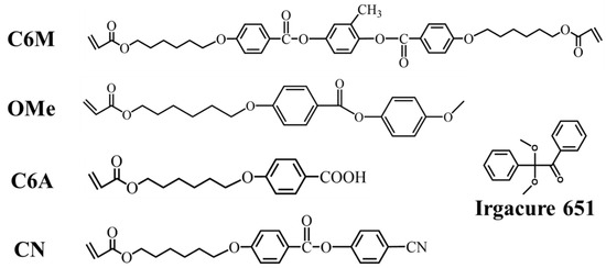
Figure 1.
Molecular structures of monomers and photoinitiators were used in this study.
Preparative process of PSLC devices: The photopolymerizable LC monomers, negative LCs, and IR 651 were mixed at 353.15 K in accordance with the ratios in Table 1. After mixing uniformly with vibrating stirring for ten minutes, the mixtures were filled at 353.15 K by capillary force into an LC cell with a 20 µm gap, a vertical alignment layer, and an ITO electrode on both internal surfaces. After keeping the sample at a temperature of 353.15 K for five min, the samples were cooled to room temperature. Subsequently, the samples were photopolymerized using 365 nm UV light with light intensities of 15 mW/cm2 for 300.0 s at room temperature. The UV lamp equipment (XM210 UVLED) was purchased from Aventk in Shanghai, China.
Measurements of Polymer Network Morphology: A scanning electron microscope (SEM, JSM-6700F, Tokyo, Japan) was used to observe the microstructures of the LC polymer network. To obtain its cross-sectional view, the samples were first soaked in cyclohexane at room temperature for five days to remove the negative nematic LC molecules, and samples only containing the polymer network were obtained. After being frozen in liquid nitrogen, LC cells were cut into identical quarters through a glass cutter. Then, those LC cells were placed at room temperature. The polymer network morphology can be observed under SEM after the samples were sprayed with gold.
Features of PSLC devices: The PSLC devices were driven by 100 Hz sinusoidal alternating current (AC), and a transformer was used to change the applied voltage. The transmittance of the PSLC devices, contrast ratio, Vth, Vsat, and response time were all tested by the LCD comprehensive parameter meter LCT-5066C. The transmittance was normalized by measuring the transmittance of air.
3. Results and Discussion
Figure 1 shows the schematic molecular structures of monomers and the photoinitiator Irgacure 651 (IR 651) used in this study. A commercial nematic LC mixture (nematic phase temperature range from 233.15 K to 380.15 K, dielectric anisotropy Δε = −4.4, and birefringence Δn = 0.180) was used as received. The photopolymerized LC monomers included three kinds of monoacrylic monomers and the diacrylic monomer C6M. The preparation process for the reverse-mode PSLC device is as follows: First, the LC mixture, photopolymerized LC monomer, and IR 651 were mixed and filled into the space between two ITO glass substrates whose surfaces were coated with a vertical alignment layer. Then, the sample was irradiated by UV light for several minutes, and the PSLC device was prepared. In previous studies, when using diacrylate monomers only, increasing the content of diacrylate monomers led to an increasing Vth for PSLC devices. In a recent study conducted by Zhou and his co-workers, it was verified that when the total concentration of polymer was set at 3.0 wt%, with an increasing concentration of monoacrylate monomer, the crosslinking density of the polymer network fell, resulting in a reduction in Vth and response time [34]. Here, we studied the PSLC with a polymer content of 7.5%, as higher polymer content would benefit a more stable polymer network and higher peel strength. Under the condition in which UV light irradiation intensity was set at 15.0 mW/cm2 and polymerizable monomer concentrations were set at 7.5 wt%, PSLC films with polymerizable monomers containing different functional groups were researched. On this basis, the role of the composition ratio of monoacrylate monomers with cyano/carboxyl functional groups to C6M in microstructures and electro-optical properties was further studied. The composition of each sample is listed in Table 1.
3.1. The Study of PSLC Films Containing Monoacrylic Monomers with Different End Groups
Under the same reaction conditions with monoacrylic monomer content remaining at 3.0 wt%, the influence exerted on polymer networks from LC monoacrylates with different functional groups can be observed in Figure 2. The cyano polymer network in Figure 2d was much sparser than that of other PSLC networks in Figure 2a–c, meaning a key role in reducing density on PSLC polymer networks was played by cyano monoacrylate monomers. The polymer network direction of methoxy monoacrylate was much more messy than the other three, which meant during the polymerization process, methoxy monoacrylate polymerized in a random direction, which was unfavorable to the uniform alignment of liquid crystals.
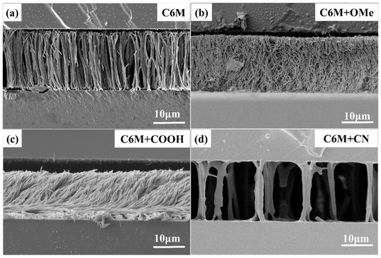
Figure 2.
PSLC polymer networks contain different monoacrylate functional groups. (a) the polymer network containing C6M only; (b) the network containing C6M and methoxy monoacrylate; (c) the network containing C6M and carboxyl monoacrylate; (d) the network containing C6M and cyano monoacrylate.
When contrasting these three peel strength curves of polymer networks with different functional groups, as shown in Figure 3f, it can be found that cyano polymer networks show the lowest peel strength, which further proves that doping cyano monoacrylate will lower the density and strength of the PSLC polymer network. Notably, as shown in Figure 3, the electro-optical properties of PSLC devices containing cyano or carboxyl functional groups performed much better than those containing other different functional groups. As in Figure 3c, the Vth of the cyano PSLC device was lower than 20 V, decreasing by a factor of over one time compared to other devices. This phenomenon indicated that a cyanopolymer network’s anchoring effect on LCs was also reduced, apart from reducing the density and strength of the polymer network. A larger interstice in the polymer network made it possible for nematic LCs to respond quicker in an electric field. It was worth noting that, just like PSLCs containing C6M only or PSLCs containing methoxy monoacrylate, the topology of PSLC films containing carboxyl monoacrylate had a dense polymer network. What distinguished it from the others was that the polymer network of the carboxyl PSLC film was much thinner, with smaller interstices between every unit. Compared with PSLCs containing C6M only, which had more bifurcations between the upper and lower substrates, the upper and lower substrates were all connected with every unit in the polymer network of the carboxyl PSLC device. Though the topology density of the carboxyl PSLC device was similar to that of the PSLC device containing methoxy monoacrylate, the orientation of the latter one was quite messy, and its topology cannot be clearly seen. However, the former had a regular orientation and obvious topology. This phenomenon is related to the existence of hydrogen bonds. The carboxyl monomer formed a biacrylate and polymerized along a vertical direction favorable for the vertical alignment of liquid crystals. On the basis of acrylate crosslinking, hydrogen bonds among molecules increase the density of the polymer network. Thus, when the voltage reached Vsat, the transmittance of carboxyl PSLC dropped to less than 10%, while the PSLC film with C6M only and the PSLC film with methoxy monomers remained above 30%, indicating the better electro-optical performance of PSLC devices containing carboxyl. Attributed to the unique polymer network morphology of carboxyl PSLC, it had the best electro-optical performance and relatively high peel strength.
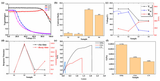
Figure 3.
Electro-optical performance curves of PSLC devices with different functional groups. (a) Voltage–transmittance curves of PSLC devices with different functional groups; (b) contrast ratio curves of PSLC devices with different functional groups; (c) threshold voltages, saturation voltages, and the difference between them of PSLC devices with different functional groups; (d) rise times and decay times of PSLC devices with different functional groups; (e) stress–strain curves of PSLC devices with different functional groups; (f) peel strength curves of PSLC devices with different functional groups.
3.2. The Study of Cyano PSLC Films
Scanning electron microscope (SEM) tests were carried out to observe the morphology of the LC polymer network. After soaking in cyclohexane for five continuous days, followed by liquid nitrogen freezing, SEM specimens can finally be treated. In this part, the morphology of the polymer network in a cyano-PSLC film will be discussed first. During the experiment, it can be figured out that when UV light intensity remains at 15 mW/cm2 with total monomer content maintained at 7.5 wt%, obvious regular characteristics can be discovered in the cyano PSLC films. From the cross-sectional view (Figure 4), it can be seen that polymer networks from Sample B2-1 to Sample D2-1 were spreading vertically in the form of dendrites between the upper and lower substrates. As the junction between the two substrates was wider than that of the middle part, this phenomenon indicated that the network aggregated along the upper or lower substrate to the middle during the polymerization process until it was connected to another substrate. Nevertheless, the network morphology of Sample E2-1 was demonstrated in a shrub shape, which represented that the polymer network did not only branch in a vertical orientation but also in a transverse orientation. Sample F2-1 presented a dense and disordered polymer network shape, showing a directional polymer network cannot be formed with only cyano monoacrylate monomers. In current basic research, PSLC films containing only monoacrylate monomers could only form side-chain liquid crystalline polymers, which made it difficult to form well-aligned directional polymer networks across the LC cells. Due to the increase in cyano monoacrylate content from Sample B2-1 to Sample D2-1, the density of the polymer network went from high to lower and then to higher again, and the pore size became larger at the beginning and then smaller. A more significant polymer network topology form in Sample D2-1 has been obviously discovered, representing a long-range ordered dendrimer network in which each dendritic polymer is in the shape of a dendritic root at the junction of the upper and lower substrates, gathers more towards the middle part, and finally merges into a dendritic trunk. As is shown in Figure 4, cyano monoacrylate and C6M polymer network topologies were more stable and long-range ordered when cyano monomer content was maintained between 3.0 wt% and 4.5 wt%.
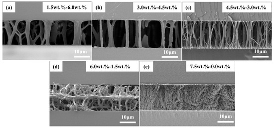
Figure 4.
SEM micrographs of cyano PSLC devices with a total polymer concentration of 7.5 wt% from a cross-sectional view. The scales of all micrographs are 10 μm. (a) Sample B2−1, (b) Sample C2−1, (c) Sample D2−1, (d) Sample E2−1, and (e) Sample F2−1, the concentration of cyano monoacrylate increases from 1.5 wt% to 7.5 wt%, while that of diacrylate decreases from 6.0 wt% to 0.0 wt%. The ratios of monoacrylate monomer to diacrylate monomer are 1.5:6.0, 3.0:4.5, 3.5:4.0, 6.0:1.5, and 7.5:0, respectively.
Figure 5a demonstrates the voltage–transmittance (V–T) curve of cyano PSLC films under a 100 Hz sinusoidal alternating current field. From Sample A2−1 to Sample D2−1 (shown in Table 1), the concentration of cyano monoacrylate increased from 0.0 wt% to 4.5 wt%, while that of C6M decreased from 7.5 wt% to 3.0 wt%. The transmittance of the cyano PSLC device was about 85% when the electric field was off (voltage is 0 V), and the differences among data from these four samples are below 2.0%. In Sample E2−1 and Sample F2−1, in which the cyano concentration was 6.0 wt% and 7.5 wt%, respectively, the transmittance of the PSLC device in the off state dropped to 80%, representing a deteriorated alignment of the polymer networks and liquid crystals. The transmittance of the pure cyano PSLC device (Sample F2−1) had reached 81%, 2.0% higher than that of Sample E2−1. The reason behind this phenomenon of transmittance variance at off-state lies in the polymer network. With relatively regular polymer networks, for the first four samples, the vertical alignment of negative nematic LC molecules in their polymer networks has a higher degree of order. By contrast, shrubby polymer networks in Sample E2−1 and Sample F2−1 have lowered the degree of order of vertical alignment, further reducing transmittance off-state. When in on-state (when the electric field is on), all PSLC devices except Sample F2−1 turn into scattering states. Under such circumstances, when the cyano concentration was set between 1.5 wt% and 4.5 wt%, the transmittance of PSLCs was less than 20%. When cyano concentration was 6.5 wt%, the transmittance of PSLCs at on-state was more than 45%, while that of pure cyano PSLC film stood at 81%, remaining unchanged. The transmittance of the PSLC device containing C6M only (Sample A2−1) was 52%. When the concentration of cyano was set between 1.5 wt% and 4.5 wt%, the scattering state at a relatively low driving voltage was formed on account of the regular topological structures of the liquid crystal polymer network. When cyano concentration increased over 6.5 wt% due to the irregular shrubby polymer network structures, both the disorder degree and negative nematic LC multi-domains increased. All these lead to a lower contrast ratio. When the concentration of cyano monoacrylate reached 7.5 wt%, the transmittance of PSLC was unchanged even at 100 V due to the anchoring effect of disordered serried polymer networks.
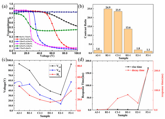
Figure 5.
Electro-optical performance curves of samples with different ratios of cyano monoacrylate monomers and diacrylate monomers. (a) Voltage–transmittance curves from Sample A2−1 to Sample F2−1; (b) contrast ratios from Sample A2−1 to Sample F2−1; (c) threshold voltages, saturation voltages, and the difference between them from Sample A2−1 to Sample F2−1; (d) rise times and decay times from Sample A2−1 to Sample F2−1.
The Vth and Vsat of PSLC films with different cyano concentrations are shown in Figure 5c. When the content of monoacrylate monomers was less than 4.5 wt% and the content of diacrylate monomers was greater than 3.0 wt%, with the increasing content of cyano monomers, the polymer network was getting thinner and sparser, and from that, its crosslinking density became lower. The anchoring force of the polymer network to the negative nematic LC molecules also decreased, so the Vth also decreased continuously. When the monoacrylate concentration was between 4.5 wt% and 6.0 wt% and the diacrylate concentration was between 1.5 wt% and 3.0 wt%, the regular topology of the polymer network gradually disappeared, with its shape changing from dendritic to shrubby, the pore size of the polymer network further decreasing, and cluttering larger-sized holes appearing. All these factors contributed to a lower anchoring force for the negative nematic LC molecules. It can be clearly seen that Sample E2−1 had a Vth of 13.5 V and a Vsat of 31.6 V, which are much lower than other PSLC films. Polymer networks formed by pure cyano monoacrylate monomers were too dense and disordered, resulting in a much stronger anchoring force for negative nematic LC molecules. In this case, the electric field could not force negative nematic LC molecules to rotate and the transmittance of PSLC to be changed. The above phenomenon is particularly obvious when it comes to rise time and decay time, especially in decay time. When the concentration of cyano monoacrylate monomers was less than 7.5 wt%, with the increase in concentration, the rise time was usually around 2.0 ms, which had a quite small fluctuation. However, with the increase in cyano monomer content, decay time first went up to 77.7 ms and then went down to 35.3 ms. This demonstrated that as the density of the polymer network increased, it took more time for the liquid crystal molecules to rotate after removing the applied voltage. When the concentration of cyano monoacrylate monomer was equal to 7.5 wt%, both the rise time and decay time of Sample F2−1 were greater than those of other samples, indicating a strong anchoring force made by an over-dense polymer network for negative nematic LC molecules, which led to an increase in response time.
3.3. The Study of Carboxyl PSLC Films
Compared with the cyano PSLC films, there was a different case in the polymer network topology of the carboxyl PSLC films. Figure 6 demonstrates SEM images of carboxyl PSLCs with different ratios of carboxyl monoacrylate monomer and diacrylate monomer C6M. The preparation conditions were the same with cyano PSLC films, which meant the UV light intensity was 15 mW/cm2, and the total monomer content was 7.5 wt%. What made a significant difference from the cyano-PSLC film was that in a carboxyl PSLC film, the density of the polymer network stood at a very high level with the addition of carboxyl monoacrylate monomer. When the carboxyl monomer content increased from 0.0 wt% to 1.5 wt%, the polymer network transformed from dendritic structures to wall-shaped structures covered in vines. As very dense vertical polymers even connected to each other, so-called wall-shaped structures covered in vines were formed. This was due to the presence of carboxyl groups and hydrogen bonds in the monoacrylate monomer, thus forming a diacrylate monomer, which increased the crosslinking density compared with the cyano PSLC.
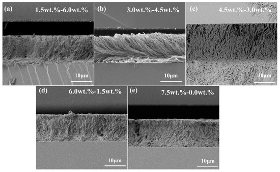
Figure 6.
SEM micrographs of carboxyl PSLC devices with a polymer concentration of 7.5% from a cross-sectional view. The scales of all micrographs are 10 μm. (a) Sample B2−2; (b) Sample C2−2; (c) Sample D2−2; (d) Sample E2−2; and (e) Sample F2−2, the concentration of carboxyl monoacrylate increases from 1.5 wt% to 7.5 wt%, while that of diacrylate decreases from 6.0 wt% to 0.0 wt%. The ratios of monoacrylate monomer to diacrylate monomer are 1.5:6.0, 3.0:4.5, 3.5:4.0, 6.0:1.5, and 7.5:0, respectively.
As a result, in the process of photopolymerization, there was not only acrylate polymerization but also interaction between hydrogen bonds among carboxyl monomers. On the macroscale, the polymer network appeared on the basis of the dendritic structures, and the connection between each tree is very dense. When the carboxyl concentration was 6.5 wt% and 7.5 wt%, as shown in Sample E2−2 and Sample F2−2, where Sample F2−2 is a pure carboxyl monoacrylate network, in particular, the wall-shaped structures covered in vines were more obvious. Different from carboxyl groups in low concentration, when the carboxyl concentration was high, vertical dendritic structures decreased, randomly oriented dendritic structures appeared, wall-shaped structures were particularly pronounced, and holes with a size of about 5.0 μm appeared intermittently. A major reason for it was the decreased concentration of diacrylate C6M, which formed polymers with little modulus in their photopolymerization with monoacrylate. The self-polymerization of carboxyl monoacrylate and the interaction of hydrogen bonds increased, leading to the consequence that the orientations of the formed polymer network became disordered and dense. What stood out in the experiment was that when the carboxyl concentration was set between 3.0 wt% and 4.5 wt%, as shown in Samples C2−2 and D2−2, the filiform topology in the carboxyl PSLC polymer network was dense with a high degree of order. This indicated the interaction between hydrogen bonds of carboxyl monoacrylate monomers was beneficial for the formation of filiform topology and enhanced density and alignment of the polymer network. The electro-optical properties of carboxyl PSLC devices were greatly affected by the remarkable features of the carboxyl PSLC polymer network, which will be discussed below.
Figure 7 shows the electro-optical performances of different carboxyl PSLC devices, which had a high correlation with their microstructures. The V–T curves of carboxyl PSLC under a sinusoidal AC electric field at 100 Hz were revealed in Figure 7a. When the voltage was turned off, the transmittance of all carboxyl PSLC devices was above 80%. When the electric field was on, whether the carboxyl concentration was between 0.0 wt% and 1.5 wt% or between 6.5 wt% and 7.5 wt%, the transmittance was still higher than 50%. This phenomenon illustrated that both a higher density and a higher degree of disorder existed in the polymer networks, which led to greater difficulties for liquid crystals to rotate under an electric field, resulting in a high driving voltage and higher transmittance at on-state. When the carboxyl concentration was set between 3.0 wt% and 4.5 wt%, the transmittance was maintained between 80% and 83% off-state. On-state, the transmittance was lower than 10%, within the range of 3% to 7%. A quite significant phenomenon can be seen that, along with increasing carboxyl concentration, the transmittance increased at both on-state and off-state. The polymer network topology difference showed that an increase in carboxyl concentration reduced the diameter of the threadlet and increased the density of the networks, which led to an increased order parameter of the negative nematic LC molecules and a higher anchoring force in a carboxyl PSLC film. It further confirmed that in carboxyl PSLC films, when the concentration of carboxyl monoacrylate monomer was 3.0 wt%, its order and density of network topology were most proper, and V–T curves had the best performance.
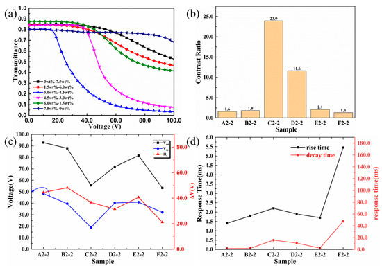
Figure 7.
Electro-optical performance curves of samples with different ratios of carboxyl monoacrylate monomers and diacrylate monomers. (a) Voltage–transmittance curves from Sample A2−2 to Sample F2−2; (b) contrast ratios from Sample A2−2 to Sample F2−2; (c) threshold voltages, saturation voltages, and the difference between them from Sample A2−2 to Sample F2−2; (d) rise times and decay times from Sample A2−2 to Sample F2−2.
Curves about Vth and Vsat of carboxyl PSLC films shown in Figure 7c also proved the superior electro-optical performances of carboxyl PSLC devices with a carboxyl concentration of 3.0 wt%. Vth of the PSLC device with other carboxyl concentrations were all above or equal to 40 V, while that of carboxyl PSLC devices with a carboxyl concentration of 3.0 wt% was 18 V, twice as low as the former. When examining the data of Vsat, except for 55 V for the carboxyl PSLC device with a carboxyl concentration of 3.0 wt%, data for other carboxyl PSLC devices are all greater than 70 V, representing an outstanding property. All these further demonstrated that the filiform LC polymer network with a carboxyl concentration of 3.0 wt% had a regular topology and long-range order. The anchoring force of polymer networks in this structure on the negative nematic LC molecules was reduced, making it easier for the molecules to rotate under the electric fields. For polymer networks with other carboxyl concentrations, wall-shaped structures led to a high anchoring force, requiring higher voltage for the negative nematic LC molecules to rotate. Furthermore, the response time shown in Figure 7d of pure carboxyl PSLC devices was far larger than that of other devices with diacrylate C6M, which demonstrated that dense wall-shaped polymer networks formed by carboxyl monomers had too strong an anchoring force for negative nematic LC molecules, which needed an obvious increased response time to rotate when the electric field was on.
4. Conclusions
The influence of monoacrylic monomer on the polymer network topology and electro-optical characteristics of reverse-mode PSLC devices have been investigated systematically. Through the study of methoxy/cyano/carboxyl monoacrylate monomers, it can be concluded that different functional groups affect polymer network morphology and lead to huge differences in electro-optical properties. Meanwhile, the composition ratio of monoacrylic and diacrylic monomers played a vital role in the modulation of the polymer network. The polymer networks of the cyano PSLC system present two different situations with the cyano concentration below and above 3.0 wt%. When the cyano concentration was below 3.0 wt%, the introduction of monoarcrylic monomers optimized the electro-optical properties of PSLC due to the sparse polymer networks and lower crosslinking density. This phenomenon validated the conclusions of the previous study. When the cyano concentration was higher than 3.0 wt%, the polymer network presented a shrubby shape, the degree of order decreased, the contrast ratio dropped by more than 90%, and both the driving voltage and response time increased. Due to the existence of hydrogen bonds, PSLC films containing carboxyl monomers show quite different polymer network morphologies. Only when the carboxyl concentration is between 3.0 wt% and 4.5 wt% can filiform structures of a polymer network with a regular topology be discovered. Within this concentration range, as the concentration increased, the transmittance decreased by 10%, the contrast ratio fell by 50%, and the driving voltage increased by 100%. When the carboxyl concentration is 3.0 wt%, the polymer network topology formed by monoacrylic carboxyl monomer and diacrylic C6M has the most excellent performance, whose density and direction with a long-range order are suitable for PSLC devices. These results indicated that doping an appropriate amount of monoarcrylic monomers containing cyano groups or hydrogen bonds into the PSLC polymer network would reduce the anchoring effect of the polymer network on liquid crystals and upgrade the electro-optical performance of PSLC devices. Additionally, the carboxyl PSLC has shown enhanced peel strength due to the denser polymer networks. Research on the above three monoacrylate monomers is of great significance for the manufacture of PSLC optical devices such as optical modulators, vehicle windows, display devices, and so on. The research also plays a guiding role in taking better control of the polymer network morphology and enriching the application scenarios of PSLC devices.
Author Contributions
Conceptualization, C.M. and C.Z.; methodology, C.M. and G.X.; validation, C.M.; formal analysis, C.M., Y.W. and Z.S.; investigation, C.Z.; resources, Y.S., M.Y. and J.X.; data curation, C.M.; writing—original draft preparation, C.M.; writing—review and editing, C.Z.; visualization, J.X., Y.G. and Q.W.; supervision, C.Z.; project administration, C.Z.; funding acquisition, J.X. and C.Z. and Q.W.; All authors have read and agreed to the published version of the manuscript.
Funding
This research was funded by the National Natural Science Foundation of China (Grant Nos. 52073028, 52203322, 52073081, and 52103071). This work was also subsidized by the Provincial Natural Science Foundation of Shandong (ZR2020ME073).
Data Availability Statement
The data supporting the findings of the study are available from the corresponding authors upon reasonable request.
Conflicts of Interest
The authors declare no conflict of interest.
References
- Zhai, Y.; Ma, Y.; David, S.N.; Zhao, D.; Lou, R.; Tan, G.; Yang, R.; Yin, X. Scalable-manufactured randomized glass-polymer hybrid metamaterial for daytime radiative cooling. Science 2017, 355, 1062–1066. [Google Scholar] [CrossRef]
- Zhang, P.; Tong, X.; Gao, Y. A Sensing and Stretchable Polymer-Dispersed Liquid Crystal Device Based on Spiderweb-Inspired Silver Nanowires-Micromesh Transparent Electrode. Adv. Funct. Mater. 2023, 33, 2303270. [Google Scholar]
- Dierking, I. Polymer network—Stabilized liquid crystals. Adv. Mater. 2000, 12, 167–181. [Google Scholar] [CrossRef]
- Li, H.; Xu, J.; Ren, Y.; Han, R.; Song, H.; Huang, R.; Wang, X.; Zhang, L.; Cao, H.; Zou, C.; et al. Preparation of Highly Durable Reverse-Mode Polymer-Stabilized Liquid Crystal Films with Polymer Walls. ACS Appl. Mater. Interfaces 2022, 15, 2228–2236. [Google Scholar] [CrossRef] [PubMed]
- Guo, S.-M.; Liang, X.; Zhang, C.-H.; Chen, M.; Shen, C.; Zhang, L.-Y.; Yuan, X.; He, B.-F.; Yang, H. Preparation of a thermally light-transmittance-controllable film from a coexistent system of polymer-dispersed and polymer-stabilized liquid crystals. ACS Appl. Mater. Interfaces 2017, 9, 2942–2947. [Google Scholar] [PubMed]
- Zhang, T.; Kashima, M.; Zhang, M.; Liu, F.; Song, P.; Zhao, X.; Zhang, C.; Cao, H.; Yang, H. Effects of the functionality of epoxy monomer on the electro-optical properties of thermally-cured polymer dispersed liquid crystal films. RSC Adv. 2012, 2, 2144–2148. [Google Scholar] [CrossRef]
- Meng, Q.; Cao, H.; Kashima, M.; Liu, H.; Yang, H. Effects of the structures of epoxy monomers on the electro-optical properties of heat-cured polymer-dispersed liquid crystal films. Liq. Cryst. 2010, 37, 189–193. [Google Scholar] [CrossRef]
- Zhang, C.; Wang, D.; Cao, H.; Song, P.; Yang, C.; Yang, H.; Hu, G.-H. Preparation and electro-optical properties of polymer dispersed liquid crystal films with relatively low liquid crystal content. Polym. Adv. Technol. 2013, 24, 453–459. [Google Scholar]
- Yu, M.; Xu, J.; Luo, L. Role of Hydroxy Group in the Electro-Optical Properties of Polymer-Dispersed Liquid Crystals. Crystals 2023, 13, 843. [Google Scholar]
- Jamil, M.; Ahmad, F.; Rhee, J.T.; Jeon, Y.J. Nanoparticle-doped polymer-dispersed liquid crystal display. Curr. Sci. 2011, 101, 1544–1552. [Google Scholar]
- Kizhakidathazhath, R.; Nishikawa, H.; Okumura, Y. High-performance polymer dispersed liquid crystal enabled by uniquely designed acrylate monomer. Polymers 2020, 12, 1625. [Google Scholar] [CrossRef] [PubMed]
- Ghosh, A. Investigation of vacuum-integrated switchable polymer dispersed liquid crystal glazing for smart window application for less energy-hungry building. Energy 2023, 265, 126396. [Google Scholar]
- Bobnar, M.; Derets, N.; Umerova, S. Polymer-dispersed liquid crystal elastomers as moldable shape-programmable material. Nat. Commun. 2023, 14, 764. [Google Scholar] [CrossRef] [PubMed]
- Hinojosa, A.; Sharma, S.C. Effects of gold nanoparticles on electro-optical properties of a polymer-dispersed liquid crystal. Appl. Phys. Lett. 2010, 97, 081114. [Google Scholar]
- Shivaraja, S.J.; Gupta, R.K.; Manjuladevi, V. Faster switching polymer dispersed liquid crystal devices incorporated with functionalized SWCNTs. J. Mol. Liq. 2022, 354, 118905. [Google Scholar] [CrossRef]
- Jiang, Z.; Zheng, J.; Liu, Y.; Zhu, Q. Investigation of dielectric properties in polymer dispersed liquid crystal films doped with CuO nanorods. J. Mol. Liq. 2019, 295, 111667. [Google Scholar] [CrossRef]
- He, Z.; Yin, K.; Hsiang, E.; Wu, S. Volumetric light-shaping polymer-dispersed liquid crystal films for mini-LED backlights. Liq. Cryst. 2020, 47, 1458–1463. [Google Scholar] [CrossRef]
- Li, X.; Guo, Y.; Huai, H.; Yang, Y.; Sun, Y.; Zhang, C.; Sun, Y. The effect of monomer and chiral dopant content on reverse-mode polymer stabilized cholesteric liquid crystal display. J. Mol. Liq. 2020, 309, 113112. [Google Scholar] [CrossRef]
- Hu, X.; Zhang, X.; Yang, W.; Jiang, X.; Jiang, X.; de Haan, L.T.; Yuan, D.; Zhao, W.; Zheng, N.; Jin, M.; et al. Stable and scalable smart window based on polymer stabilized liquid crystals. J. Appl. Polym. Sci. 2020, 137, 48917. [Google Scholar] [CrossRef]
- Zhao, R.; Li, X.; Wang, K.; Huai, H.; Ma, H.; Sun, Y. Effect of the introduction of mono-functional monomer on the electro-optic properties of reverse-mode polymer stabilised cholesteric liquid crystal. Liq. Cryst. 2021, 48, 1162–1174. [Google Scholar]
- Chen, Y.X.; Hsu, J.S. Ultra-low switching reverse mode liquid crystal gels. Opt. Express 2020, 28, 26783–26791. [Google Scholar] [CrossRef]
- Meng, C.; Tseng, M.C.; Tang, S.T.; Zhao, C.X.; Yeung, S.Y.; Kwok, H.S. Normally transparent smart window with haze enhancement via inhomogeneous alignment surface. Liq. Cryst. 2019, 46, 484–491. [Google Scholar] [CrossRef]
- Liu, S.; Li, Y.; Zhou, P.; Chen, Q.; Su, Y. Reverse-mode PSLC multi-plane optical see-through display for AR applications. Opt. Express 2018, 26, 3394–3403. [Google Scholar] [CrossRef] [PubMed]
- Kikuchi, H.; Yamamoto, H.; Sato, H.; Kawakita, M.; Takizawa, K.; Fujikake, H. Formation of polymer-wall-stabilized bend-mode liquid crystal cells. J. Photopolym. Sci. Technol. 2003, 16, 181–186. [Google Scholar] [CrossRef]
- Gheorghiu, N.; West, J.L.; Glushchenko, A.V.; Mitrokhin, M. Patterned field induced polymer walls for smectic A bistable flexible displays. Appl. Phys. Lett. 2006, 88, 263511. [Google Scholar] [CrossRef]
- Yu, H.H.; Hwang, S.J.; Chen, R.L.; Yang, C.Y. Study of the purifying affects of thermal annealing for polymer-wall liquid crystal cells. Liq. Cryst. 2008, 35, 1339–1343. [Google Scholar] [CrossRef]
- Song, D.H.; Lee, S.R.; Yoon, T.; Kim, J.C. Multi-dimensional liquid crystal alignment effect of polymer wall on vertically aligned liquid crystal cell. Jpn. J. Appl. Phys. 2010, 49, 11702. [Google Scholar] [CrossRef]
- Lee, Y.; Jang, S.; Jung, J.; Kim, H.-R.; Jin, M.Y.; Choi, Y.; Kim, J.-H. Mechanical stability of pixel-isolated liquid crystal mode for flexible display application. Mol. Cryst. Liq. Cryst. 2006, 458, 81–87. [Google Scholar] [CrossRef]
- Zheng, W.; Lee, M.C. Attainment of planarly aligned liquid crystal using vertical alignment polymer walls. Mol. Cryst. Liq. Cryst. 2012, 553, 28–35. [Google Scholar] [CrossRef]
- Liang, X.; Guo, S.; Chen, M. A temperature and electric field-responsive flexible smart film with full broadband optical modulation. Mater. Horiz. 2017, 4, 878–884. [Google Scholar] [CrossRef]
- Guo, S.; Liang, X.; Zhang, H. An electrically light-transmittance-controllable film with a low-driving voltage from a coexistent system of polymer-dispersed and polymer-stabilised cholesteric liquid crystals. Liq. Cryst. 2018, 45, 1854–1860. [Google Scholar] [CrossRef]
- Liang, X.; Guo, C.; Chen, M. A roll-to-roll process for multi-responsive soft-matter composite films containing CsxWO3 nanorods for energy-efficient smart window applications. Nanoscale Horiz. 2017, 2, 319–325. [Google Scholar] [CrossRef] [PubMed]
- Liang, X.; Chen, M.; Guo, S. Programmable electro-optical performances in a dual-frequency liquid crystals/polymer composite system. Polymer 2018, 149, 164–168. [Google Scholar] [CrossRef]
- Zhou, Y.; You, Y.; Liao, X.; Liu, W.; Zhou, L.; Zhang, B.; Zhao, W.; Hu, X.; Zhang, L.; Yang, H.; et al. Effect of polymer network topology on the electro-optical performance of polymer stabilized liquid crystal (PSLC) devices. Macromol. Chem. Phys. 2020, 221, 2000185. [Google Scholar] [CrossRef]
Disclaimer/Publisher’s Note: The statements, opinions and data contained in all publications are solely those of the individual author(s) and contributor(s) and not of MDPI and/or the editor(s). MDPI and/or the editor(s) disclaim responsibility for any injury to people or property resulting from any ideas, methods, instructions or products referred to in the content. |
© 2023 by the authors. Licensee MDPI, Basel, Switzerland. This article is an open access article distributed under the terms and conditions of the Creative Commons Attribution (CC BY) license (https://creativecommons.org/licenses/by/4.0/).