


Micro Arc Oxidation of Mechanically Alloyed Binary Zn-1X (X = Mg or Sr) Alloys


Abstract
:1. Introduction
2. Materials and Methods
- Zn-1Mg alloy after 24 h of mechanical alloying is labeled M24.
- Zn-1Mg alloy after 48 h of mechanical alloying is labeled M48.
- Zn-1Sr alloy after 24 h of mechanical alloying is labeled S24.
- Zn-1Sr alloy after 48 h of mechanical alloying is labeled S48.
3. Results and Discussion
4. Conclusions
Author Contributions
Funding
Data Availability Statement
Conflicts of Interest
References
- Levy, G.K.; Goldman, J.; Aghion, E. The Prospects of Zinc as a Structural Material for Biodegradable Implants—A Review Paper. Metals 2017, 7, 402. [Google Scholar] [CrossRef]
- Li, H.F.; Xie, X.H.; Zheng, Y.F.; Cong, Y.; Zhou, F.Y.; Qiu, K.J.; Wang, X.; Chen, S.H.; Huang, L.; Tian, L.; et al. Development of Biodegradable Zn-1X Binary Alloys with Nutrient Alloying Elements Mg, Ca and Sr. Sci. Rep. 2015, 5, 10719. [Google Scholar] [CrossRef] [PubMed]
- Mostaed, E.; Sikora-Jasinska, M.; Mostaed, A.; Loffredo, S.; Demir, A.G.; Previtali, B.; Mantovani, D.; Beanland, R.; Vedani, M. Novel Zn-Based Alloys for Biodegradable Stent Applications: Design, Development and in Vitro Degradation. J. Mech. Behav. Biomed. Mater. 2016, 60, 581–602. [Google Scholar] [CrossRef] [PubMed]
- Hernández-Escobar, D.; Champagne, S.; Yilmazer, H.; Dikici, B.; Boehlert, C.J.; Hermawan, H. Current Status and Perspectives of Zinc-Based Absorbable Alloys for Biomedical Applications. Acta Biomater. 2019, 97, 1–22. [Google Scholar] [CrossRef]
- Pachla, W.; Przybysz, S.; Jarzębska, A.; Bieda, M.; Sztwiertnia, K.; Kulczyk, M.; Skiba, J. Structural and Mechanical Aspects of Hypoeutectic Zn–Mg Binary Alloys for Biodegradable Vascular Stent Applications. Bioact. Mater. 2021, 6, 26–44. [Google Scholar] [CrossRef]
- Hussain, M.; Ullah, S.; Raza, M.R.; Abbas, N.; Ali, A. Recent Developments in Zn-Based Biodegradable Materials for Biomedical Applications. J. Funct. Biomater. 2023, 14, 1. [Google Scholar] [CrossRef]
- Yang, H.; Jia, B.; Zhang, Z.; Qu, X.; Li, G.; Lin, W.; Zhu, D.; Dai, K.; Zheng, Y. Alloying Design of Biodegradable Zinc as Promising Bone Implants for Load-Bearing Applications. Nat. Commun. 2020, 11, 401. [Google Scholar] [CrossRef]
- Li, H.; Yang, H.; Zheng, Y.; Zhou, F.; Qiu, K.; Wang, X. Design and Characterizations of Novel Biodegradable Ternary Zn-Based Alloys with IIA Nutrient Alloying Elements Mg, Ca and Sr. Mater. Des. 2015, 83, 95–102. [Google Scholar] [CrossRef]
- Gu, X.N.; Xie, X.H.; Li, N.; Zheng, Y.F.; Qin, L. In Vitro and in Vivo Studies on a Mg-Sr Binary Alloy System Developed as a New Kind of Biodegradable Metal. Acta Biomater. 2012, 8, 2360–2374. [Google Scholar] [CrossRef]
- Ward, B.C.; Webster, T.J. Increased Functions of Osteoblasts on Nanophase Metals. Mater. Sci. Eng. C 2007, 27, 575–578. [Google Scholar] [CrossRef]
- Webster, T.J.; Siegel, R.W.; Bizios, R. Nanoceramic Surface Roughness Enhances Osteoblast and Osteoclast Functions for Improved Orthopaedic/Dental Implant Efficacy. Scr. Mater. 2001, 44, 1639–1642. [Google Scholar] [CrossRef]
- Sotoudeh Bagha, P.; Khaleghpanah, S.; Sheibani, S.; Khakbiz, M.; Zakeri, A. Characterization of Nanostructured Biodegradable Zn-Mn Alloy Synthesized by Mechanical Alloying. J. Alloys Compd. 2018, 735, 1319–1327. [Google Scholar] [CrossRef]
- Tian, Q.; Rivera-Castaneda, L.; Liu, H. Optimization of Nano-Hydroxyapatite/Poly(Lactic-Co-Glycolic Acid) Coatings on Magnesium Substrates Using One-Step Electrophoretic Deposition. Mater. Lett. 2017, 186, 12–16. [Google Scholar] [CrossRef]
- Shen, S.; Cai, S.; Zhang, M.; Xu, G.; Li, Y.; Ling, R.; Wu, X. Microwave Assisted Deposition of Hydroxyapatite Coating on a Magnesium Alloy with Enhanced Corrosion Resistance. Mater. Lett. 2015, 159, 146–149. [Google Scholar] [CrossRef]
- Goller, G.; Oktar, F.N.; Ozyegin, L.S.; Kayali, E.S.; Demirkesen, E. Plasma-Sprayed Human Bone-Derived Hydroxyapatite Coatings: Effective and Reliable. Mater. Lett. 2004, 58, 2599–2604. [Google Scholar] [CrossRef]
- Song, G.; StJohn, D. The Effect of Zirconium Grain Refinement on the Corrosion Behaviour of Magnesium-Rare Earth Alloy MEZ. J. Light. Met. 2002, 2, 1–16. [Google Scholar] [CrossRef]
- Kowalski, K.; Nowak, M.; Jakubowicz, J.; Jurczyk, M. The Effects of Hydroxyapatite Addition on the Properties of the Mechanically Alloyed and Sintered Mg-RE-Zr Alloy. J. Mater. Eng. Perform. 2016, 25, 4469–4477. [Google Scholar] [CrossRef]
- Khodaei, M.; Nejatidanesh, F.; Shirani, M.J.; Valanezhad, A.; Watanabe, I.; Savabi, O. The Effect of the Nano- Bio-glass Reinforcement on Magnesium Based Composite. J. Mech. Behav. Biomed. Mater. 2019, 100, 103396. [Google Scholar] [CrossRef]
- Miklaszewski, A.; Kowalski, K.; Jurczyk, M. Hydrothermal Surface Treatment of Biodegradable Mg-Materials. Metals 2018, 8, 894. [Google Scholar] [CrossRef]
- Datta, M.K.; Chou, D.T.; Hong, D.; Saha, P.; Chung, S.J.; Lee, B.; Sirinterlikci, A.; Ramanathan, M.; Roy, A.; Kumta, P.N. Structure and Thermal Stability of Biodegradable Mg-Zn-Ca Based Amorphous Alloys Synthesized by Mechanical Alloying. Mater. Sci. Eng. B 2011, 176, 1637–1643. [Google Scholar] [CrossRef]
- Safaie, N.; Khakbiz, M.; Sheibani, S.; Bagha, P.S. Synthesizing of Nanostructured Fe-Mn Alloys by Mechanical Alloying Process. Procedia Mater. Sci. 2015, 11, 381–385. [Google Scholar] [CrossRef]
- Salleh, E.M.; Ramakrishnan, S.; Hussain, Z. Synthesis of Biodegradable Mg-Zn Alloy by Mechanical Alloying: Effect of Milling Time. Procedia Chem. 2016, 19, 525–530. [Google Scholar] [CrossRef]
- Marczewski, M.; Jurczyk, M.U.; Kowalski, K.; Miklaszewski, A.; Wirstlein, P.K.; Jurczyk, M. Composite and Surface Functionalization of Ultrafine-Grained Ti23Zr25Nb Alloy for Medical Applications. Materials 2020, 13, 5252. [Google Scholar] [CrossRef] [PubMed]
- Jurczyk, K.; Braegger, U.; Jurczyk, M. Application of Nanotechnology for Dental Implants. In Handbook of Nanoethics; Jeswani, G., van de Voorde, M., Eds.; De Gruyter: Berlin, Germany, 2021; Volume 5, pp. 75–94. ISBN 9783110669282. [Google Scholar]
- Nečas, D.; Kubásek, J.; Pinc, J.; Marek, I.; Donik, Č.; Paulin, I.; Vojtěch, D. Ultrafine-Grained Zn–Mg–Sr Alloy Syn-thesized by Mechanical Alloying and Spark Plasma Sintering. Materials 2022, 15, 8379. [Google Scholar] [CrossRef] [PubMed]
- Tuliński, M.; Jurczyk, M. Nanomaterials Synthesis Methods. In Metrology and Standardization of Nanotechnology: Protocols and Industrial Innovations; Nanotechnology Innovation & Applications; Wiley-VCH: Weinheim, Germany, 2017; pp. 75–98. ISBN 9783527340392. [Google Scholar]
- Yuan, W.; Xia, D.; Wu, S.; Zheng, Y.; Guan, Z.; Rau, J.V. A Review on Current Research Status of the Surface Modification of Zn-Based Biodegradable Metals. Bioact. Mater. 2022, 7, 192–216. [Google Scholar] [CrossRef] [PubMed]
- Yuan, W.; Li, B.; Chen, D.; Zhu, D.; Han, Y.; Zheng, Y. Formation Mechanism, Corrosion Behavior, and Cytocompatibility of Microarc Oxidation Coating on Absorbable High-Purity Zinc. ACS Biomater. Sci. Eng. 2019, 5, 487–497. [Google Scholar] [CrossRef] [PubMed]
- Hu, Z.; Chen, Q.; Li, Z.; Yu, Y.; Peng, L.M. Large-Scale and Rapid Synthesis of Ultralong ZnO Nanowire Films via Anodization. J. Phys. Chem. C 2010, 114, 881–889. [Google Scholar] [CrossRef]
- Kim, S.J.; Choi, J. Self-Assembled Arrays of ZnO Stripes by Anodization. Electrochem. Commun. 2008, 10, 175–179. [Google Scholar] [CrossRef]
- Zhao, J.; Wang, X.; Liu, J.; Meng, Y.; Xu, X.; Tang, C. Controllable Growth of Zinc Oxide Nanosheets and Sunflower Structures by Anodization Method. Mater. Chem. Phys. 2011, 126, 555–559. [Google Scholar] [CrossRef]
- Faid, A.Y.; Allam, N.K. Stable Solar-Driven Water Splitting by Anodic ZnO Nanotubular Semiconducting Photoanodes. RSC Adv. 2016, 6, 80221–80225. [Google Scholar] [CrossRef]
- Shi, Z.; Liu, M.; Atrens, A. Measurement of the Corrosion Rate of Magnesium Alloys Using Tafel Extrapolation. Corros. Sci. 2010, 52, 579–588. [Google Scholar] [CrossRef]
- Gittens, R.A.; Scheideler, L.; Rupp, F.; Hyzy, S.L.; Geis-Gerstorfer, J.; Schwartz, Z.; Boyan, B.D. A Review on the Wettability of Dental Implant Surfaces II: Biological and Clinical Aspects. Acta Biomater. 2014, 10, 2907–2918. [Google Scholar] [CrossRef] [PubMed]
- Falde, E.J.; Yohe, S.T.; Colson, Y.L.; Grinstaff, M.W. Superhydrophobic Materials for Biomedical Applications. Biomaterials 2016, 104, 87–103. [Google Scholar] [CrossRef]
- Gilani, S.; Ghorbanpour, M.; Parchehbaf Jadid, A. Antibacterial Activity of ZnO Films Prepared by Anodizing. J. Nanostructure Chem. 2016, 6, 183–189. [Google Scholar] [CrossRef]


| Sample | a [Å] | c [Å] | V [Å3] | ρth [g/cm3] | ρ [g/cm3] | Porosity [%] | HV0.3 |
|---|---|---|---|---|---|---|---|
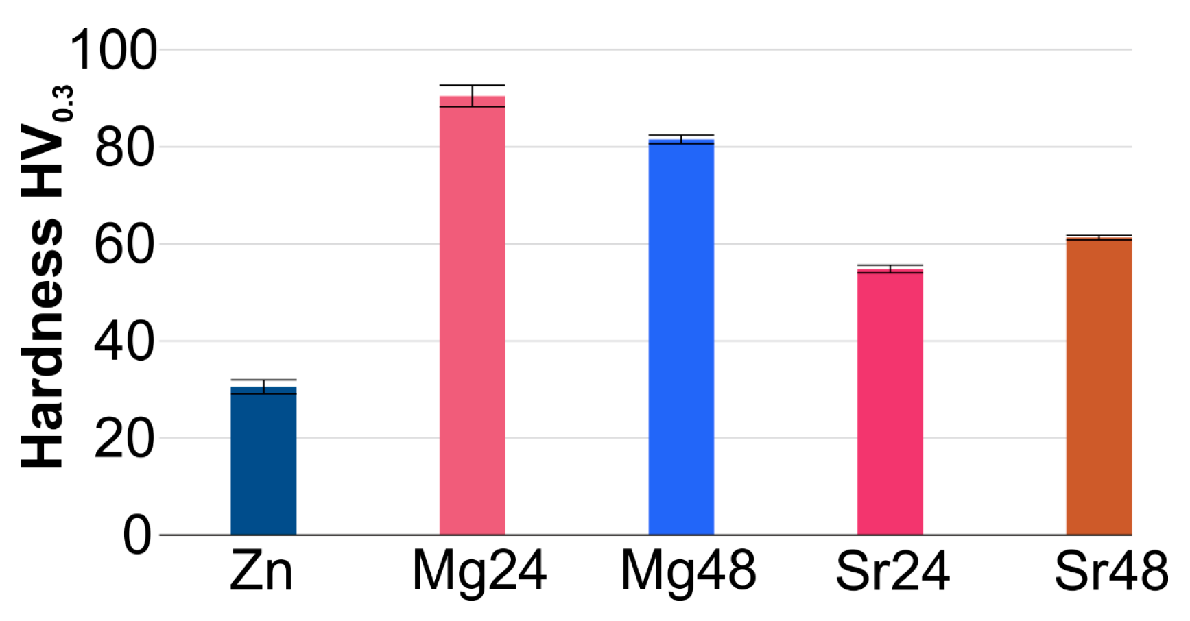
| Zn | 2.6612 | 4.9428 | 30.3148 | 7.133 | 6.929 ± 0.004 | 2.86 ± 0.07 | 30.5 ± 1.44 |
| M24 | 2.6643 | 4.9442 | 30.3953 | 6.925 | 6.543 ± 0.011 | 5.45 ± 0.18 | 90.5 ± 2.23 |
| M48 | 2.6626 | 4.9428 | 30.3457 | 6.925 | 6.377 ± 0.008 | 7.85 ± 0.23 | 81.5 ± 0.87 |
| S24 | 2.6622 | 4.9397 | 30.3181 | 7.017 | 6.416 ± 0.015 | 8.60 ± 0.29 | 54.8 ± 0.82 |
| S48 | 2.6643 | 4.9456 | 30.4029 | 7.017 | 6.203 ± 0.022 | 11.64 ± 0.41 | 61.3 ± 0.42 |
| Sample | Ic [µA/cm2] | Ec [V] | Water CA [°] | Glycerol CA [°] | SFE [mN/m] | Disperse [mN/m] | Polar [mN/m] |
|---|---|---|---|---|---|---|---|
| Zn | 3.885 | −1.548 | 44.45 ± 1.1 | 70.21 ± 1.9 | 87.76 ± 6.0 | 0.81 ± 0.7 | 86.95 ± 5.3 |
| M24 | 6.641 | −1.581 | 54.20 ± 0.1 | 57.88 ± 0.7 | 47.48 ± 1.7 | 6.70 ± 0.7 | 40.78 ± 1.1 |
| M48 | 1.885 | −1.550 | 74.08 ± 0.7 | 54.51 ± 0.3 | 43.88 ± 2.3 | 37.74 ± 1.6 | 6.14 ± 0.7 |
| S24 | 5.680 | −1.535 | 50.03 ± 3.7 | 48.73 ± 0.2 | 49.23 ± 10.1 | 12.42 ± 3.3 | 36.81 ± 6.8 |
| S48 | 2.884 | −1.542 | 71.58 ± 0.3 | 46.34 ± 0.1 | 53.77 ± 0.9 | 49.29 ± 0.7 | 4.48 ± 0.1 |
| Sample | Ic [µA/cm2] | Ec [V] | Water CA [°] | Glycerol CA [°] | SFE [mN/m] | Disperse [mN/m] | Polar [mN/m] |
|---|---|---|---|---|---|---|---|
| Zn | 0.995 | −1.474 | 101.54 ± 1.4 | 123.02 ± 1.9 | 37.58 ± 4.4 | 5.73 ± 1.2 | 31.84 ± 3.2 |
| M24 | 0.241 | −1.471 | 74.62 ± 0.2 | 106.77 ± 0.7 | 95.98 ± 2.8 | 15.09 ± 1.1 | 80.80 ± 1.7 |
| M48 | 1.605 | −1.472 | 140.71 ± 0.1 | 93.09 ± 0.0 | 99.54 ± 0.5 | 78.13 ± 0.3 | 21.41 ± 0.2 |
| S24 | 2.237 | −1.562 | 116.79 ± 0.50 | 139.92 ± 0.5 | 26.44 ± 1.4 | 6.49 ± 0.5 | 19.94 ± 0.9 |
| S48 | 0.546 | −1.556 | 126.91 ± 0.25 | 102.86 ± 0.5 | 29.01 ± 1.3 | 27.13 ± 1.1 | 1.88 ± 0.2 |
Disclaimer/Publisher’s Note: The statements, opinions and data contained in all publications are solely those of the individual author(s) and contributor(s) and not of MDPI and/or the editor(s). MDPI and/or the editor(s) disclaim responsibility for any injury to people or property resulting from any ideas, methods, instructions or products referred to in the content. |
© 2023 by the authors. Licensee MDPI, Basel, Switzerland. This article is an open access article distributed under the terms and conditions of the Creative Commons Attribution (CC BY) license (https://creativecommons.org/licenses/by/4.0/).
Share and Cite
Kowalski, K.; Drzewiecki, M.; Jurczyk, M. Micro Arc Oxidation of Mechanically Alloyed Binary Zn-1X (X = Mg or Sr) Alloys. Crystals 2023, 13, 1503. https://doi.org/10.3390/cryst13101503
Kowalski K, Drzewiecki M, Jurczyk M. Micro Arc Oxidation of Mechanically Alloyed Binary Zn-1X (X = Mg or Sr) Alloys. Crystals. 2023; 13(10):1503. https://doi.org/10.3390/cryst13101503
Chicago/Turabian StyleKowalski, Kamil, Michał Drzewiecki, and Mieczysław Jurczyk. 2023. "Micro Arc Oxidation of Mechanically Alloyed Binary Zn-1X (X = Mg or Sr) Alloys" Crystals 13, no. 10: 1503. https://doi.org/10.3390/cryst13101503
APA StyleKowalski, K., Drzewiecki, M., & Jurczyk, M. (2023). Micro Arc Oxidation of Mechanically Alloyed Binary Zn-1X (X = Mg or Sr) Alloys. Crystals, 13(10), 1503. https://doi.org/10.3390/cryst13101503