Article

Micro Arc Oxidation of Mechanically Alloyed Binary Zn-1X (X = Mg or Sr) Alloys

by
Kamil Kowalski
1,*,
Michał Drzewiecki
1 and
Mieczysław Jurczyk
2
1
Institute of Materials Science and Engineering, Poznan University of Technology, Jana Pawla II 24, 61-138 Poznan, Poland
2
Department of Biomedical Engineering, Institute of Materials and Biomedical Engineering, Faculty of Mechanical Engineering, University of Zielona Gora, Prof. Z. Szafrana 4, 65-516 Zielona Gora, Poland
*
Author to whom correspondence should be addressed.
Crystals 2023, 13(10), 1503; https://doi.org/10.3390/cryst13101503
Submission received: 13 September 2023 / Revised: 6 October 2023 / Accepted: 14 October 2023 / Published: 16 October 2023
(This article belongs to the Special Issue Advances in New Functional Biomaterials for Medical Applications)

Abstract

:
The binary Zn-1wt.% X (X = Mg or Sr) alloys prepared by the application of mechanical alloying (MA) combined with powder metallurgy were modified by micro-arc oxidation (MAO) treatment in the 2 g/dm3 KOH aqueous solution at 200 V for 1 min for the formation of the ZnO layer. The Zn-alloys, obtained through the powder metallurgy method, are characterized by a dispersive microstructure that significantly improves its microhardness up to 90.5 HV0.3 for the Zn-1wt.%Mg sample after 24 h of MA. In the case of Zn-1Mg alloy after 24 h of mechanical alloying, Zn-1Mg alloy after 48 h of mechanical alloying, and Zn-1Sr alloy after 48 h of mechanical alloying, except for the main αZn phase, the traces of a second phase are noticed: MgZn2 and SrZn13. After the proposed MAO treatment, a zinc oxide (ZnO) layer on the zinc alloys was formed, allowing a significant improvement in the corrosion resistance and surface wetting properties. The potential of the modified ZnO layer is moved to more noble values in the case of MAO-treated samples α-Zn, Zn-1Mg (after 24 h of MA), and Zn-1Sr (after 48 h of MA). The obtained results show a good prospective potential of Zn-1wt.% X (X = Mg or Sr) binary alloys in the application of biodegradable materials.

1. Introduction

In the past years, biodegradable alloys on the base of zinc have been developed [1,2,3,4,5]. The next generation of orthopedic implants can avoid revisions. Pure Zn is brittle, and its mechanical properties are not sufficient for implant applications. Zinc alloys are receiving increasing attention as biodegradable biomaterials owing to their two exceptional properties [4]: (i) a substantial role in the growth of new cells and bone metabolism, and (ii) a moderate degradation rate compared to iron- and magnesium-based biomaterials without excessive hydrogen release during the corrosive process.
The current research aimed to develop a Zn-based system with properties suitable for biomedical material applications, including orthopedic practice [5,6,7,8]. Binary Zn-X alloys (X = Mg, Ca, Sr, Li, Mn, and so on) with Zn as the primary component have shown encouraging results as orthopedic implants in terms of both biomechanics and bioactivity [3,4,5,6,7,8,9]. For example, the influence of different elements such as Sr, Mg, and Ca on the microstructure, mechanical, and corrosion behavior, along with hemocompatibility, in vitro cytocompatibility, and in vivo biocompatibility, was studied in the case of rolled and extruded binary Zn-1X alloys [2,8,9]. In correlation with pure Zn, the enhancement of mechanical properties, corrosion behavior, and biocompatibility was detected. However, the corrosion rate of the Zn-1X alloys is observably higher compared to pure Zn, and the sequence is Zn < Zn-1Mg < Zn-1Ca < Zn-1Sr.
The mechanical and elastic properties of Zn metal were improved by alloying with Mg. But 5 wt.% of magnesium in Zn boosts its hardness and corrosion rate [5,8]. Strontium improved the mechanical properties, corrosion behavior, and biocompatibility of Zn metal [2,8,9].
There is a need for compositional chemical modification of pure Zn due to its poor mechanical properties [1,3,4]. Two known classifications distinguish bulk or surface modification approaches [10,11,12,13,14,15,16,17,18,19]. The first one is related to grain refinement, and the second leads to surface modification. In the case of Zn-based alloys, surface modification methods include the chemical methods used for obtaining different coatings on the surface of the materials. High surface energy can be created in the case of nanosurfaces. These phenomena lead to improved initial protein adsorption, which plays an important role in regulating cellular interactions on the biomaterial surface [10,11]. Recently, it was noted that the roughness of the metallic nanostructures has an impact on the adhesion of osteoblast cells and their spread and proliferation.
The physicochemical and mechanical properties of metallic biomaterials can be improved through microstructure control [17,18]. The combination of mechanical alloying (MA) and powder metallurgy can finally synthesize nanostructured bulk materials [19]. The application of the mechanical alloying route influenced the properties of alloys [12,20,21,22,23,24]. MA is a powder processing technique that involves repeated welding and fracturing of starting powders [25,26]. Finally, the obtained powder mixture can be consolidated into bulk biomaterials with a controlled microstructure.
Nanostructuring enhances both mechanical properties and the biocompatibility of materials [10,11]. Recently, biodegradable Zn-xMn (x = 0, 4, and 24 wt.% Mn) alloys with nanostructures were prepared by mechanical alloying and cold pressing [12]. The crystallite size of the sintered alloys reached 80 nm. The presence of MnZn13 in the second phase affected the mechanical properties and corrosion resistance. The nanostructured Zn-4Mn alloy shows a compressive yield strength of 290 MPa with a corrosion rate of 0.72 mm/yr.
The suitable corrosion behavior combined with the excellent biocompatibility of biomaterials can be optimized during the surface modification process. Recently, surface modification of Zn-based alloys has been a wide research area in terms of adjusting their corrosion properties [27,28]. In the case of Zn-type alloys addressed to orthopedic applications, different surface modification methods were proposed [27]: chemical (phosphate conversion coating, organic and polymer coating, biomimetic deposition, stabilization treatment), electrochemical (micro-arc oxidation—400 V/3 min; as electrolyte: 2.5 g/L sodium hydroxide with an addition of 0.02 mol/L calcium were used), physical (atomic layer deposition, magnetron sputtering), and mechanical (sandblasting). In the case of micro-arc oxidation, enhanced cell adhesion and reduced cell proliferation were detected [28].
The application of anodic oxidation on the surface of zinc and its alloys can create nanostructures with different morphologies: nanowires [29], nanostrips [30], nanosheets [31], and nanotubes [32]. In the case of the micro-arc oxidation process, homogeneous micropores can be created, which accelerate the corrosion rate of α-Zn [28].
This paper presents a proposal for a multilevel approach that combines considerations related to the chemical composition, microstructure, and surface state for the enhancement of the properties of biodegradable Zn alloys. In the present study, the binary Zn-1wt.% X (X = Mg or Sr) alloys obtained by the application of mechanical alloying and powder metallurgy approaches were modified by MAO treatment for the formation of the ZnO layer. The microstructure, microhardness, and corrosion behavior were systematically studied to investigate their feasibility as bioabsorbable implants. The properties of the sinters presented in this paper allow examination of the influence of different factors, such as composition or surface state, on the corrosion properties and contact angle measurements.

2. Materials and Methods

Binary zinc alloys with an addition of 1 wt.% magnesium or strontium were prepared by a combination of the mechanical alloying process and powder metallurgy. Elemental powders of Zn (99% purity, maximum particle size 600 µm; Sigma Aldrich, St. Louis, MO, USA), magnesium (99.8% purity, maximum particle size 45 µm; Alfa-Aesar, Haverhill, MA, USA), and Sr (99% purity, maximum particle size 600 µm; Alfa-Aesar, Haverhill, USA) were weighted and loaded into vials in a protective argon atmosphere in the Labmaster 130 (MBraun, München, Germany). Mechanical alloying was carried out in a shaker-type mill, Spex 8000M (Spex Sample Prep LLC, Metuchen, NJ, USA), with a ball-to-powder ratio of 10:1 at ambient temperature for 24 and 48 h in a continuous mode. Hardened steel vials with a capacity of 40 mL and bearing steel balls with different diameters were used. There were 12 mills with diameters ranging from 6 mm to 18 mm. The sizes were selected based on our preliminary studies. The milling time was set to 24 h and 48 h in continuous mode without additives from the process control agent.
The powders were uniaxially pressed at a compacting pressure of 600 MPa on a Hydropras hydraulic press (Skalar-Elektromechanika, Warsaw Poland). Green compacts were heat treated at 300 °C for 1 h under vacuum conditions in a tube furnace to form bulk samples with dimensions of 8 mm in diameter and 3 mm high. The temperature of sintering was selected based on our preliminary studies to avoid unwanted liquid phases. After sintering, the samples were ground in sandpaper up to 1200 grit and polished with diamond suspension (up to 1 µm). Before SEM and optical microscopy observation, samples were electrochemically polished in a phosphoric acid and ethanol solution.
Part of the samples was treated by the MAO process in the 2 g/dm3 KOH aqueous solution at 200 V for 1 min—Figure 1. Finally, the samples were washed with alcohol and distilled water, dried in hot air, and subsequently assessed visually for the uniformity of the coating layer.
For brevity, in this paper, alloys are signified as follows:
  • Zn-1Mg alloy after 24 h of mechanical alloying is labeled M24.
  • Zn-1Mg alloy after 48 h of mechanical alloying is labeled M48.
  • Zn-1Sr alloy after 24 h of mechanical alloying is labeled S24.
  • Zn-1Sr alloy after 48 h of mechanical alloying is labeled S48.
A scanning electron microscope (SEM) (Mira 3, TESCAN, Brno, Czech Republic) equipped with energy dispersive spectrometry (EDS) was used for microstructure observation and chemical composition of the obtained samples after MAO treatment analysis. X-ray diffractometer (XRD, PANalytical Empyrean, Almelo, The Netherlands) using CuKα (λ = 1.54056 Å) was operated at 40 kV and 45 mA to determine the phase composition of powders and sinters in a scanning range of 2θ (30–80°) at a scan rate of 2°/min−1 and step of 0.033°.
The Innovatest Nexus 4000 Vickers tester equipment (INNOVATEST Europe BV, Maastricht, The Netherlands) was used for the microhardness test. A load of 300 g for 10 s was used. To obtain an average value of the microhardness, 10 indents per sample were made. Before microhardness measurements, the surface of the tested alloys was polished.
Ringer’s solution was chosen for the corrosion test of the produced binary alloys. (BTL Zakład Enzymow i Peptonow, Lodz, Poland). The solution contains: NaCl: 9 g/L; KCl: 0.42 g/L; CaCl2: 0.48 g/L; and NaHCO3: 0.2 g/L. The Solartron 1285 (Solartron Analytical, Farnborough, UK) potentiostat works in a potentiodynamic mode with a scan rate of 1 mV/s in the established potential range of −0.7 V to +2.5 V vs. open circuit potential (OCP). The constant solution temperature was maintained at 37 °C, which simulates the human body temperature. The reference and counter electrodes were made of Pt and graphite, respectively.
The wettability properties of surfaces were studied by recording contact angle (CA) by the visual system equipped with a digital camera (Kruss-DSA25, KRÜSS GmbH, Hamburg, Germany) and measured via Kruss-Advanced 1.5 software (KRÜSS GmbH, Hamburg, Germany). For the surface-stating CA measurements, deionized water and glycerin (99.9%, Chemland, Stargard, Poland) were selected as testing liquids. The sessile drop mode was employed to place the droplets with a constant volume of 1.5 µL of testing fluids on the surface of materials by dedicated micropipette systems. The CA was determined from the geometrical shape of the droplets using the Young-Laplace function with manual baseline correction. Measured data were collected at a frequency of 20 fps after droplet placement for 10 s. To obtain reliable data and eliminate any errors or experimental mistakes, the procedure was repeated three times. The surface free energy (SFE) of the analyzed samples was assessed using the Owens, Wendt, Rabel, and Kaelble (OWRK) model, which is based on Fowkes and uses contact angles of two liquids with known polar and dispersed components of surface free energy (SFE). More experimental details are available [19,33].

3. Results and Discussion

The binary Zn-1wt.% X (X = Mg or Sr) alloys obtained by the application of mechanical alloying and powder metallurgy methods The influence of different factors, such as chemical composition, microstructure, and surface state, was studied. The property enhancement of biodegradable Zn alloys was detected.
Figure 2 depicts SEM images of initial powders before the process of mechanical alloying. All used powders have irregular shapes, with zinc granules measuring over 200 µm, magnesium powder particles measuring about 50 µm, and strontium powder tending to form aggregates and agglomerates.
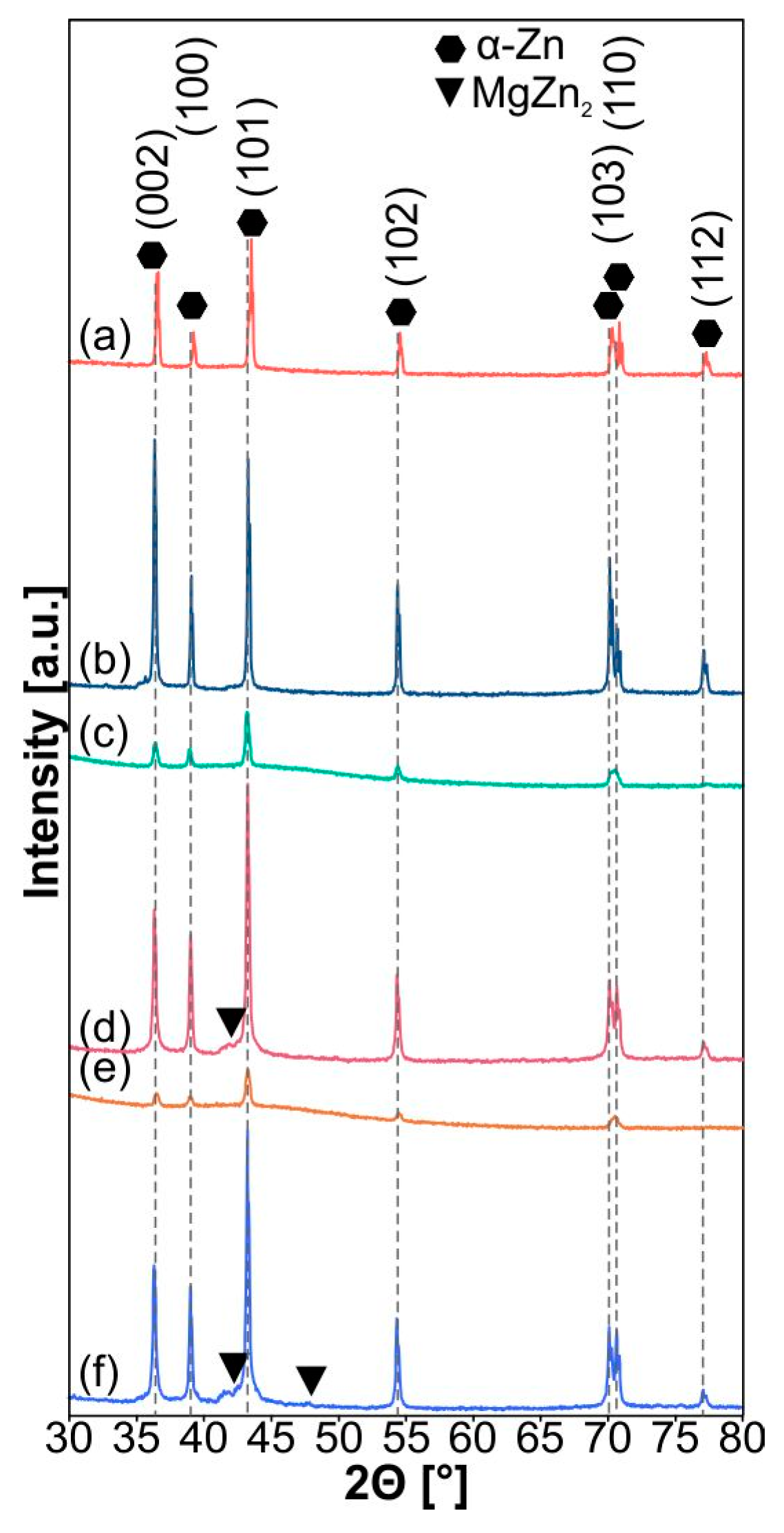
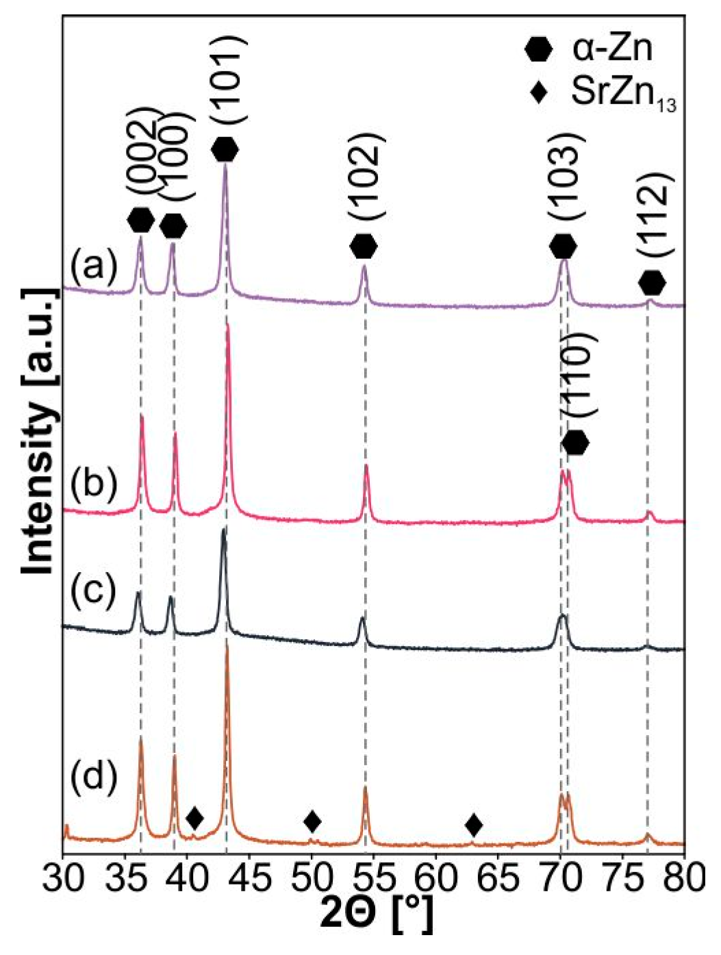
The XRD patterns of pure Zn powder, sintered Zn, M24 powder after MA, M24 after sintering, M48 powder after MA process, and M48 after sintering, S24 powder after MA, S24 sintered, S48 powder after MA process, and S48 sintered are presented in Figure 3 and Figure 4. Sintering results in the formation of bulk materials (Figure 5 and Figure 6). A single-phase, α-Zn type was obtained in the case of S24. For the M24, M48, and S48 sinters accepting the α-Zn phase (ICDD: 01-087-0713), traces of MgZn2 (ICDD: 03-065-3578) and SrZn13 (ICDD: 03-065-3125) phases were detected. Its content equals 1%, 2%, and 4% of M24, M48, and S48 sinters, respectively. MgZn2 crystallizes in the hexagonal P63/mmc space group (a = 5.16 Å, c = 8.37 Å), and SrZn13 crystallizes in the cubic Fm-3c space group (a = 12.24 Å). The gray lines in Figure 3 and Figure 4 indicate the positions of the matched α-Zn phases. The details of the unit cell dimensions of the synthesized alloys are summarized in Table 1.
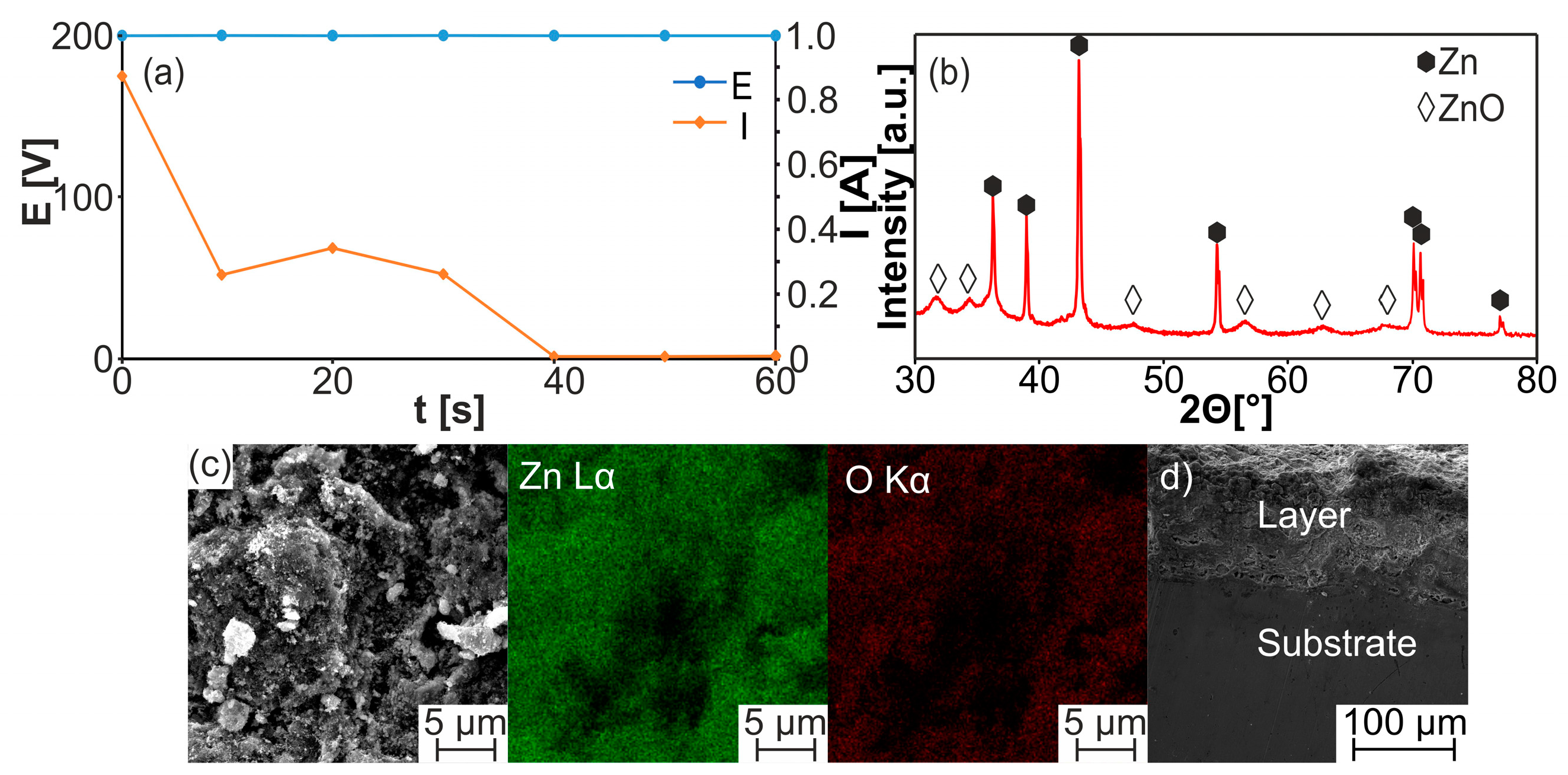
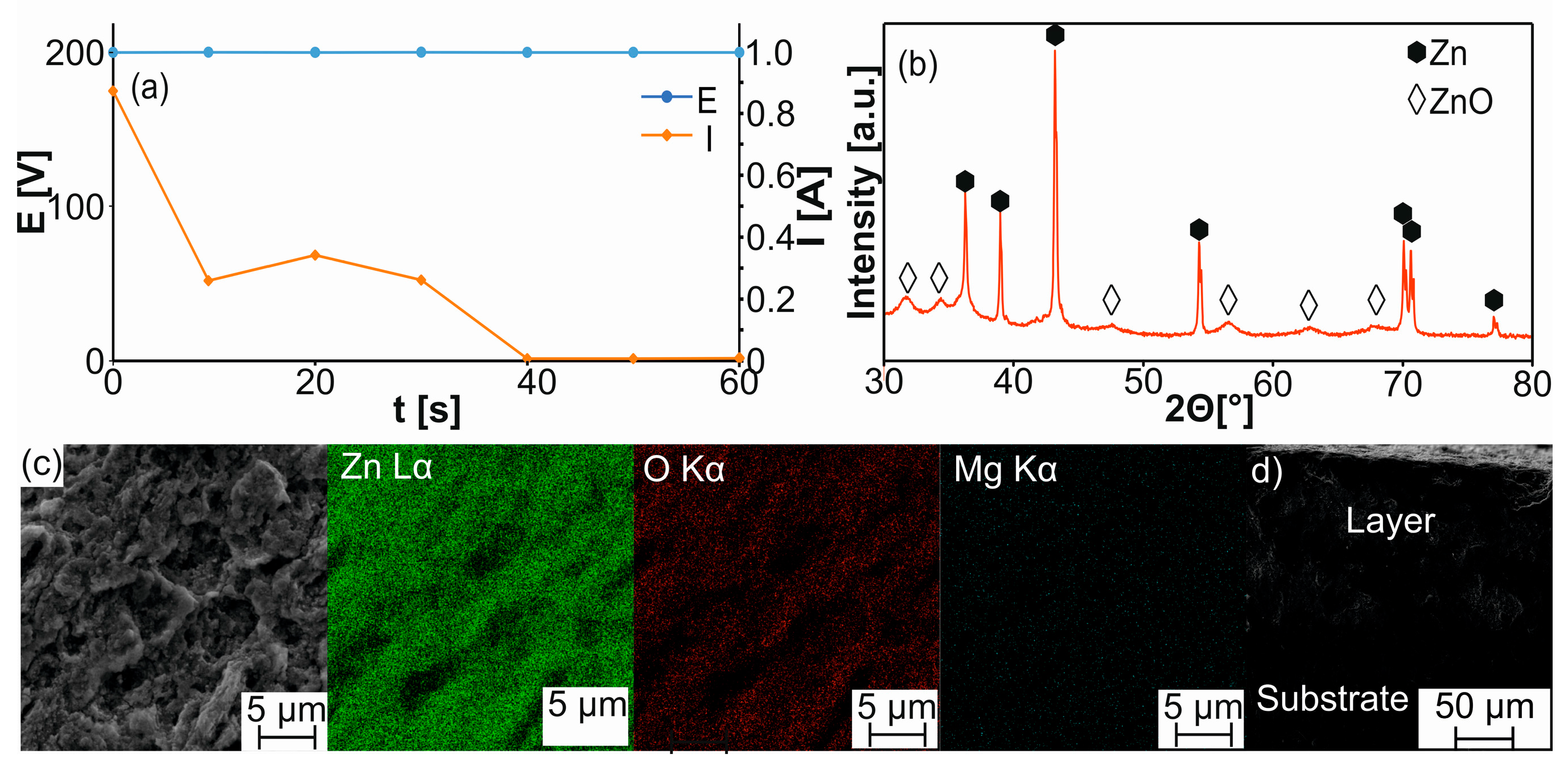
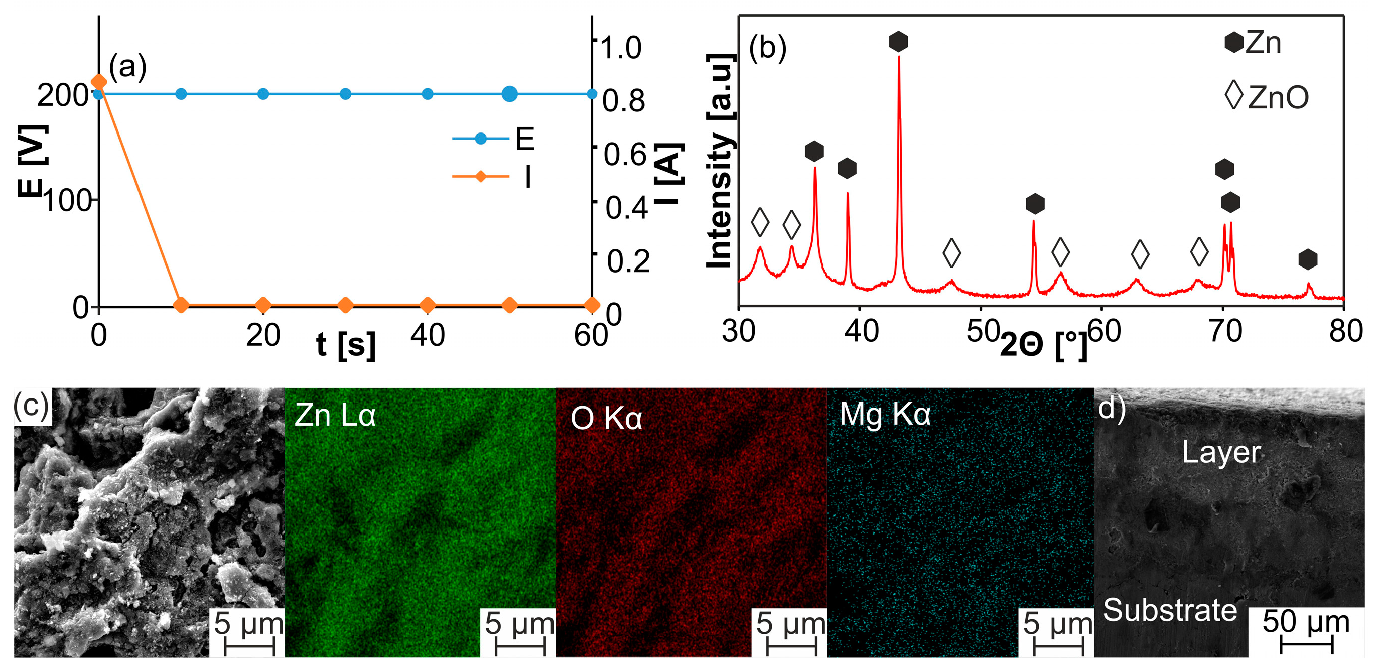
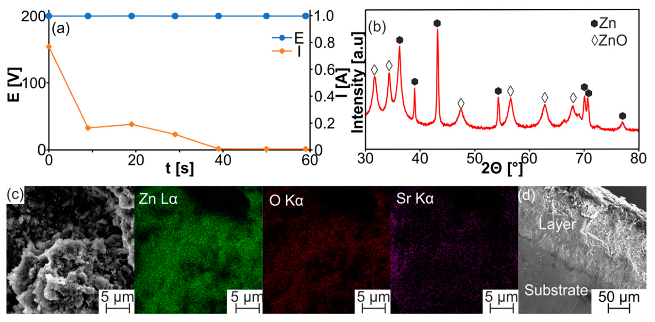
The bulk Zn-type alloys were modified by the MAO treatment in the 2 g/dm3 KOH aqueous solution (Figure 7, Figure 8, Figure 9, Figure 10 and Figure 11). The XRD analysis confirms the ZnO layer formation for each sample after the MAO process, which is also visible on the SEM images on the surface and in the cross-section sample profile view. In addition to zinc reflexes, all oxidized sample XRD patterns additionally confirmed the existence of ZnO (ICDD: 01-089-7102). The thickness of the obtained zinc oxide layers shown in Figure 7, Figure 8, Figure 9, Figure 10 and Figure 11 differs from 60 to 100 µm.
For all samples, the MAO process shows a similar character during the first 20–30 s, when a great reduction of current takes place, except for the pure Zn sample (Figure 7a). Formed layers contain ZnO in all cases, and XRD studies of the produced samples showed that the crystallinity of oxide layers depends on the substrate structure. For the samples modified with magnesium (both M24 and M48—Figure 8b and Figure 9b) show a lower intensity of ZnO phases compared to pure Zn and S24 and S48 samples. For all modified samples, there are visible traces of Mg or strontium in the produced layers.
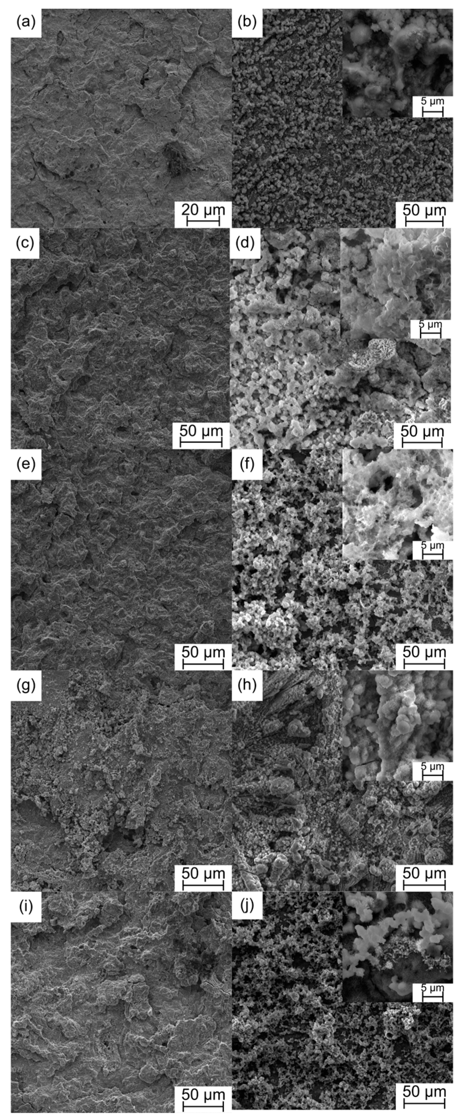
As a result of the MAO process, the surface of all bulk alloys was characterized by highly developed topography and porosity, facilitating the process of osseointegration (Figure 12). Furthermore, the comparison of all MAO-treated sinters before and after soaking in Ringer solution for 7 days shows corrosion products. During the soaking in Ringer’s solution, the corrosion process leads to the formation of other phases with different morphologies. For pure zinc, the surface shows a uniform distribution of corrosion products. On the modified samples, partial dissolution of the oxide layer is visible. Formed corrosion products are characterized by different morphologies. For the M24 sample, flower-like corrosion products are formed. More developed surfaces are visible for the M48 and S48 samples. For the S48 samples, after soaking, platelet-shaped corrosion products are visible. XRD analysis indicated the presence of oxide, carbonate, and hydroxide layers deposited on the top surface of the samples (Figure 13). The presence of these phases on the surface of the zinc alloy can impact the corrosion behavior of the alloy. The substrate influences the formation of corrosion products on the surface. For the samples containing magnesium, the peaks from the formed phases seem to be smaller and have a lower intensity, while for the strontium-containing samples (both S24 and S48), the peaks from the Zn(OH)2 are sharper and have a higher intensity, which indicates that these phases are more crystalline. However, for the S24 and S48 samples, the formation of carbonate layers appears to be hindered.
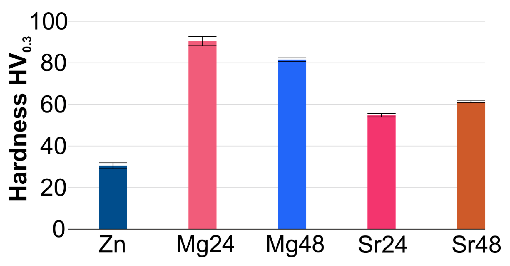
The different alloy compositions produced in this study allow for the obtaining of biomaterials with significantly different microhardnesses (Table 1, Figure 14). The analysis confirmed that the synthesis of ultrafine-grained microstructure in all alloy compositions increases the microhardness results obtained for all tested samples. The highest microhardness of 90.5 HV0.3 exceeds the starting values three times in the case of the M24 alloy (Zn-reference sample). The results of microhardness are characterized by low variability, which confirms that the ultrafine-grained microstructure is homogeneous. The sintered, unmodified Zn sample has the lowest hardness, 30.52 HV0.3. The addition of Mg and Sr led to the enhancement of the microhardness to 90.50 HV0.3 (M24), 81.54 HV0.3 (M48), 54.83 HV0.3 (S24), and 61.30 HV0.3 (S48), respectively. The occurrence of additional phases (MgZn2) for the M24 and M48 and SrZn13 for the S48 sample combined with an ultrafine-grained structure after mechanical alloying has a positive impact on the microhardness. The same microhardness was observed earlier in the as-cast and the as-rolled Zn-1X (X-Mg, Sr) alloys [2]. In the case of the M24 sinter, their microhardness is much higher in the as-cast Zn-1Mg alloy (78.26 ± 2.84) HV [2].
The water and glycerin contact angle measurements of the produced alloys and the modified surfaces have been summarized in Table 2 and Table 3. Before MAO treatment, all samples showed hydrophilic character, and all contact angles were below 90°. MAO treatment showed that the contact angle significantly increased except for the M24 sample in the case of water, which means that wettability decreased. The surfaces are hydrophobic. The change of two or more surface characteristics at the same time, such as surface roughness and chemistry, complicates the evaluation of the roles of the parameters on wetting behavior [34]. The free surface energy after ZnO deposition in the cases of α-Zn, S24, and S48 decreased. For example, for α-Zn, the SFE decreased from 87.76 mN/m to 37.58 mN/m. On the other hand, for M24 and M48 sinters, an increase in surface energy was observed.
Results in Table 2 and Table 3 confirmed that different processing approaches influence the SFE and that it is dependent on internal material characteristics. Secondly, for the additional modified surfaces after the MAO process, we observed a change in SFE, which for the proposed treatment justifies the investigated functionalization step. Low SFE corresponds to high wetting properties, which for the hard tissue replacement application remain crucial, especially at the level of molecular activity at the interface region of the host.
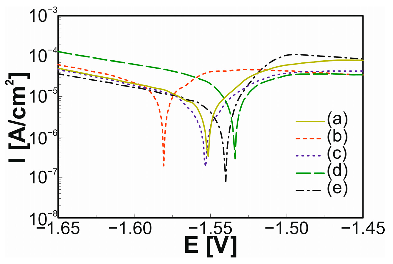
The potentiodynamic test results in Ringer’s solution are summarized in Figure 15 and Figure 16 and Table 2 and Table 3. It is important to note that the potential of the modified ZnO layer is shifted to more noble values in the case of MAO-treated samples α-Zn, M24, and M48. The addition of Mg and Sr to Zn metal had a positive impact on the corrosion resistance in Ringer’s solution. The bulk samples of M48 and S48 have better corrosion resistance (Ic = 1.885 µA/cm2, Ec = −1.5502 V; Ic = 2.884 µA/cm2, Ec = −1.5421 V) than the α-Zn metal (Ic = 3.885 µA/cm2). The best corrosion resistance is shown by M24 and S48 sinters after MAO treatment and ZnO deposition (Ic = 0.241 µA/cm2, Ec = −1.4709 V; Ic = 0.546 µA/cm2, Ec = −1.5559 V, respectively). According to the studies [2], the corrosion rates of the binary Zn-1X samples were 0.17 and 0.22 mm/year for the Zn–1Mg and Zn–1Sr pins, respectively, which is below the daily allowed dose of zinc.
MAO treatment of Zn-1wt.% X alloys in the 2 g/dm3 KOH aqueous solution at 200 V for 1 min forms the developed surface of ZnO. The resulting coatings have a thickness of 60–100 μm. EDS analysis confirmed the presence of Zn ions and oxygen after treatment and their uniform distribution. The applied surface treatment resulted in an improvement in its corrosion resistance, but the surfaces are hydrophobic, except for the M24 sinter (only in water). As was shown in our study, the 1 wt.% of the dopants (Mg, Sr) decreased the current densities for the MAO surfaces in correlation to the untreated surfaces.
Hydrophobic surfaces in the biomedical field are a great area of interest, such as in controlling protein adsorption, cellular interaction, and bacterial growth, as well as platforms for diagnostic tools and different medication delivery devices [35].
Recently, the ZnO micro/nanohole array and nanoparticle array on Zn foil were synthesized by anodic oxidation [36]. These arrays proved to have greater antibacterial properties against both Gram-negative E. coli and Gram-positive S. aureus.

4. Conclusions

The conducted research shows that the ultrafine-grained Zn-1wt.% X (X = Mg or Sr) binary possesses a highly dispersed and homogeneous microstructure. The results of microhardness are characterized by low variability. The pure Zn sinter has a low hardness of only 30.52 HV0.3. After alloying with Mg and Sr, the microhardness is significantly enhanced to 90.50 HV0.3 (M24), 81.54 HV0.3 (M48), 54.83 HV0.3 (S24), and 61.30 HV0.3 (S48), respectively.
The addition of Mg and Sr to Zn metal had a positive effect on the corrosion resistance in Ringer’s solution. Moreover, the application of the MAO process in the aqueous KOH solution results in the formation of a dense and homogeneous zinc oxide layer on the synthesized substrates. The highly developed ZnO layer on the surface of binary alloys reduces corrosion and enhances wetting behavior. The potential of the modified ZnO layer is moved to more noble values in the case of MAO-treated samples a-Zn, M24, and M48. The best corrosion resistance is shown by M24 and S48 sinters after MAO treatment and ZnO deposition (Ic = 0.241 µA/cm2, Ec = −1.4709 V; Ic = 0.546 µA/cm2, Ec = −1.5559 V, respectively). The results obtained show a good prospective potential of ultrafine-grained Zn-1wt.% X (X = Mg or Sr) binary alloys in the application of biodegradable materials.

Author Contributions

K.K. and M.D. conducted the experimental and analytical work. K.K. and M.J. wrote the manuscript. K.K. supervised the project. All authors have read and agreed to the published version of the manuscript.

Funding

This work was financed by the National Science Centre Poland under decision no. DEC-2017/27/N/ST8/01556.

Data Availability Statement

The data presented in this study are available on request from the corresponding author.

Conflicts of Interest

The authors declare no conflict of interest.

References

  1. Levy, G.K.; Goldman, J.; Aghion, E. The Prospects of Zinc as a Structural Material for Biodegradable Implants—A Review Paper. Metals 2017, 7, 402. [Google Scholar] [CrossRef]
  2. Li, H.F.; Xie, X.H.; Zheng, Y.F.; Cong, Y.; Zhou, F.Y.; Qiu, K.J.; Wang, X.; Chen, S.H.; Huang, L.; Tian, L.; et al. Development of Biodegradable Zn-1X Binary Alloys with Nutrient Alloying Elements Mg, Ca and Sr. Sci. Rep. 2015, 5, 10719. [Google Scholar] [CrossRef] [PubMed]
  3. Mostaed, E.; Sikora-Jasinska, M.; Mostaed, A.; Loffredo, S.; Demir, A.G.; Previtali, B.; Mantovani, D.; Beanland, R.; Vedani, M. Novel Zn-Based Alloys for Biodegradable Stent Applications: Design, Development and in Vitro Degradation. J. Mech. Behav. Biomed. Mater. 2016, 60, 581–602. [Google Scholar] [CrossRef] [PubMed]
  4. Hernández-Escobar, D.; Champagne, S.; Yilmazer, H.; Dikici, B.; Boehlert, C.J.; Hermawan, H. Current Status and Perspectives of Zinc-Based Absorbable Alloys for Biomedical Applications. Acta Biomater. 2019, 97, 1–22. [Google Scholar] [CrossRef]
  5. Pachla, W.; Przybysz, S.; Jarzębska, A.; Bieda, M.; Sztwiertnia, K.; Kulczyk, M.; Skiba, J. Structural and Mechanical Aspects of Hypoeutectic Zn–Mg Binary Alloys for Biodegradable Vascular Stent Applications. Bioact. Mater. 2021, 6, 26–44. [Google Scholar] [CrossRef]
  6. Hussain, M.; Ullah, S.; Raza, M.R.; Abbas, N.; Ali, A. Recent Developments in Zn-Based Biodegradable Materials for Biomedical Applications. J. Funct. Biomater. 2023, 14, 1. [Google Scholar] [CrossRef]
  7. Yang, H.; Jia, B.; Zhang, Z.; Qu, X.; Li, G.; Lin, W.; Zhu, D.; Dai, K.; Zheng, Y. Alloying Design of Biodegradable Zinc as Promising Bone Implants for Load-Bearing Applications. Nat. Commun. 2020, 11, 401. [Google Scholar] [CrossRef]
  8. Li, H.; Yang, H.; Zheng, Y.; Zhou, F.; Qiu, K.; Wang, X. Design and Characterizations of Novel Biodegradable Ternary Zn-Based Alloys with IIA Nutrient Alloying Elements Mg, Ca and Sr. Mater. Des. 2015, 83, 95–102. [Google Scholar] [CrossRef]
  9. Gu, X.N.; Xie, X.H.; Li, N.; Zheng, Y.F.; Qin, L. In Vitro and in Vivo Studies on a Mg-Sr Binary Alloy System Developed as a New Kind of Biodegradable Metal. Acta Biomater. 2012, 8, 2360–2374. [Google Scholar] [CrossRef]
  10. Ward, B.C.; Webster, T.J. Increased Functions of Osteoblasts on Nanophase Metals. Mater. Sci. Eng. C 2007, 27, 575–578. [Google Scholar] [CrossRef]
  11. Webster, T.J.; Siegel, R.W.; Bizios, R. Nanoceramic Surface Roughness Enhances Osteoblast and Osteoclast Functions for Improved Orthopaedic/Dental Implant Efficacy. Scr. Mater. 2001, 44, 1639–1642. [Google Scholar] [CrossRef]
  12. Sotoudeh Bagha, P.; Khaleghpanah, S.; Sheibani, S.; Khakbiz, M.; Zakeri, A. Characterization of Nanostructured Biodegradable Zn-Mn Alloy Synthesized by Mechanical Alloying. J. Alloys Compd. 2018, 735, 1319–1327. [Google Scholar] [CrossRef]
  13. Tian, Q.; Rivera-Castaneda, L.; Liu, H. Optimization of Nano-Hydroxyapatite/Poly(Lactic-Co-Glycolic Acid) Coatings on Magnesium Substrates Using One-Step Electrophoretic Deposition. Mater. Lett. 2017, 186, 12–16. [Google Scholar] [CrossRef]
  14. Shen, S.; Cai, S.; Zhang, M.; Xu, G.; Li, Y.; Ling, R.; Wu, X. Microwave Assisted Deposition of Hydroxyapatite Coating on a Magnesium Alloy with Enhanced Corrosion Resistance. Mater. Lett. 2015, 159, 146–149. [Google Scholar] [CrossRef]
  15. Goller, G.; Oktar, F.N.; Ozyegin, L.S.; Kayali, E.S.; Demirkesen, E. Plasma-Sprayed Human Bone-Derived Hydroxyapatite Coatings: Effective and Reliable. Mater. Lett. 2004, 58, 2599–2604. [Google Scholar] [CrossRef]
  16. Song, G.; StJohn, D. The Effect of Zirconium Grain Refinement on the Corrosion Behaviour of Magnesium-Rare Earth Alloy MEZ. J. Light. Met. 2002, 2, 1–16. [Google Scholar] [CrossRef]
  17. Kowalski, K.; Nowak, M.; Jakubowicz, J.; Jurczyk, M. The Effects of Hydroxyapatite Addition on the Properties of the Mechanically Alloyed and Sintered Mg-RE-Zr Alloy. J. Mater. Eng. Perform. 2016, 25, 4469–4477. [Google Scholar] [CrossRef]
  18. Khodaei, M.; Nejatidanesh, F.; Shirani, M.J.; Valanezhad, A.; Watanabe, I.; Savabi, O. The Effect of the Nano- Bio-glass Reinforcement on Magnesium Based Composite. J. Mech. Behav. Biomed. Mater. 2019, 100, 103396. [Google Scholar] [CrossRef]
  19. Miklaszewski, A.; Kowalski, K.; Jurczyk, M. Hydrothermal Surface Treatment of Biodegradable Mg-Materials. Metals 2018, 8, 894. [Google Scholar] [CrossRef]
  20. Datta, M.K.; Chou, D.T.; Hong, D.; Saha, P.; Chung, S.J.; Lee, B.; Sirinterlikci, A.; Ramanathan, M.; Roy, A.; Kumta, P.N. Structure and Thermal Stability of Biodegradable Mg-Zn-Ca Based Amorphous Alloys Synthesized by Mechanical Alloying. Mater. Sci. Eng. B 2011, 176, 1637–1643. [Google Scholar] [CrossRef]
  21. Safaie, N.; Khakbiz, M.; Sheibani, S.; Bagha, P.S. Synthesizing of Nanostructured Fe-Mn Alloys by Mechanical Alloying Process. Procedia Mater. Sci. 2015, 11, 381–385. [Google Scholar] [CrossRef]
  22. Salleh, E.M.; Ramakrishnan, S.; Hussain, Z. Synthesis of Biodegradable Mg-Zn Alloy by Mechanical Alloying: Effect of Milling Time. Procedia Chem. 2016, 19, 525–530. [Google Scholar] [CrossRef]
  23. Marczewski, M.; Jurczyk, M.U.; Kowalski, K.; Miklaszewski, A.; Wirstlein, P.K.; Jurczyk, M. Composite and Surface Functionalization of Ultrafine-Grained Ti23Zr25Nb Alloy for Medical Applications. Materials 2020, 13, 5252. [Google Scholar] [CrossRef] [PubMed]
  24. Jurczyk, K.; Braegger, U.; Jurczyk, M. Application of Nanotechnology for Dental Implants. In Handbook of Nanoethics; Jeswani, G., van de Voorde, M., Eds.; De Gruyter: Berlin, Germany, 2021; Volume 5, pp. 75–94. ISBN 9783110669282. [Google Scholar]
  25. Nečas, D.; Kubásek, J.; Pinc, J.; Marek, I.; Donik, Č.; Paulin, I.; Vojtěch, D. Ultrafine-Grained Zn–Mg–Sr Alloy Syn-thesized by Mechanical Alloying and Spark Plasma Sintering. Materials 2022, 15, 8379. [Google Scholar] [CrossRef] [PubMed]
  26. Tuliński, M.; Jurczyk, M. Nanomaterials Synthesis Methods. In Metrology and Standardization of Nanotechnology: Protocols and Industrial Innovations; Nanotechnology Innovation & Applications; Wiley-VCH: Weinheim, Germany, 2017; pp. 75–98. ISBN 9783527340392. [Google Scholar]
  27. Yuan, W.; Xia, D.; Wu, S.; Zheng, Y.; Guan, Z.; Rau, J.V. A Review on Current Research Status of the Surface Modification of Zn-Based Biodegradable Metals. Bioact. Mater. 2022, 7, 192–216. [Google Scholar] [CrossRef] [PubMed]
  28. Yuan, W.; Li, B.; Chen, D.; Zhu, D.; Han, Y.; Zheng, Y. Formation Mechanism, Corrosion Behavior, and Cytocompatibility of Microarc Oxidation Coating on Absorbable High-Purity Zinc. ACS Biomater. Sci. Eng. 2019, 5, 487–497. [Google Scholar] [CrossRef] [PubMed]
  29. Hu, Z.; Chen, Q.; Li, Z.; Yu, Y.; Peng, L.M. Large-Scale and Rapid Synthesis of Ultralong ZnO Nanowire Films via Anodization. J. Phys. Chem. C 2010, 114, 881–889. [Google Scholar] [CrossRef]
  30. Kim, S.J.; Choi, J. Self-Assembled Arrays of ZnO Stripes by Anodization. Electrochem. Commun. 2008, 10, 175–179. [Google Scholar] [CrossRef]
  31. Zhao, J.; Wang, X.; Liu, J.; Meng, Y.; Xu, X.; Tang, C. Controllable Growth of Zinc Oxide Nanosheets and Sunflower Structures by Anodization Method. Mater. Chem. Phys. 2011, 126, 555–559. [Google Scholar] [CrossRef]
  32. Faid, A.Y.; Allam, N.K. Stable Solar-Driven Water Splitting by Anodic ZnO Nanotubular Semiconducting Photoanodes. RSC Adv. 2016, 6, 80221–80225. [Google Scholar] [CrossRef]
  33. Shi, Z.; Liu, M.; Atrens, A. Measurement of the Corrosion Rate of Magnesium Alloys Using Tafel Extrapolation. Corros. Sci. 2010, 52, 579–588. [Google Scholar] [CrossRef]
  34. Gittens, R.A.; Scheideler, L.; Rupp, F.; Hyzy, S.L.; Geis-Gerstorfer, J.; Schwartz, Z.; Boyan, B.D. A Review on the Wettability of Dental Implant Surfaces II: Biological and Clinical Aspects. Acta Biomater. 2014, 10, 2907–2918. [Google Scholar] [CrossRef] [PubMed]
  35. Falde, E.J.; Yohe, S.T.; Colson, Y.L.; Grinstaff, M.W. Superhydrophobic Materials for Biomedical Applications. Biomaterials 2016, 104, 87–103. [Google Scholar] [CrossRef]
  36. Gilani, S.; Ghorbanpour, M.; Parchehbaf Jadid, A. Antibacterial Activity of ZnO Films Prepared by Anodizing. J. Nanostructure Chem. 2016, 6, 183–189. [Google Scholar] [CrossRef]
Figure 1. Schematic illustration of the experiment procedure.
Crystals 13 01503 g001
Figure 2. Morphology of the starting powders: (a) zinc; (b) magnesium; (c) strontium.
Crystals 13 01503 g002
Figure 3. XRD patterns of (a) pure Zn powder; (b) sintered Zn; (c) M24 powder after MA; (d) M24 after sintering; (e) M48 powder after MA process; (f) M48 after sintering.
Crystals 13 01503 g003
Figure 4. XRD patterns of (a) S24 powder after MA; (b) S24 sintered; (c) S48 powder after MA process; (d) S48 sintered.
Crystals 13 01503 g004
Figure 5. SEM images of (a) M24 powder after 24 h MA; (b) M48 powder after 48 h MA; (c) M24 after sintering; (d) M48 after sintering.
Crystals 13 01503 g005
Figure 6. SEM images of (a) S24 powder after 24 h MA; (b) S48 powder after 48 h MA; (c) S24 after sintering; and (d) S48 after sintering.
Crystals 13 01503 g006
Figure 7. (a) Voltage and current changes during MAO treatment in 2 g/dm3 KOH at 200 V DC for 60 s; (b) XRD pattern of the Zn sample after the MAO process; (c) SEM image of the surface with EDS maps; (d) cross-section of the sample.
Crystals 13 01503 g007
Figure 8. (a) Voltage and current changes during the MAO process; (b) XRD pattern of the M24 sample after the MAO process in 2 g/dm3 KOH at 200 V DC for 60 s; (c) SEM image of the surface with EDS maps; (d) cross-section of the sample.
Crystals 13 01503 g008
Figure 9. (a) Voltage and current changes during the MAO process; (b) XRD pattern of the M48 sample after the MAO process in 2 g/dm3 KOH at 200 V DC for 60 s; (c) SEM image of the surface with EDS maps; (d) cross-section of the sample.
Crystals 13 01503 g009
Figure 10. (a) Voltage and current changes during the MAO process; (b) XRD pattern of the S24 sample after the MAO process in 2 g/dm3 KOH at 200 V DC for 60 s; (c) SEM image of the surface with EDS maps; (d) cross-section of the sample.
Crystals 13 01503 g010
Figure 11. (a) Voltage and current changes during the MAO process; (b) XRD pattern of the S48 sample after the MAO process in 2 g/dm3 KOH at 200 V DC for 60 s; (c) SEM image of the surface with EDS maps; (d) cross-section of the sample.
Crystals 13 01503 g011
Figure 12. SEM images of the surface of (a) pure Zn after MAO treatment and (b) after soaking in Ringer solution for 7 days; (c) M24 after MAO treatment and (d) after soaking in Ringer solution for 7 days; (e) M48 after MAO treatment and (f) immersed in Ringer solution for 7 days; (g) S24 after MAO treatment and (h) soaked in Ringer solution for 7 days; and (i) S48 after MAO treatment and (j) soaked in Ringer solution for 7 days.
Crystals 13 01503 g012
Figure 13. XRD patterns of (a) pure Zn; (b) M24; (c) M48; (d) S24; and (e) S48 after MAO treatment soaked in Ringer solution for 7 days.
Crystals 13 01503 g013
Figure 14. Microhardness of studied materials.
Crystals 13 01503 g014
Figure 15. Potentiodynamic polarization curves of (a) pure Zn, (b) M24, (c) M48, (d) S24, and (e) S48.
Crystals 13 01503 g015
Figure 16. Potentiodynamic polarization curves of MAO treated: (a) pure Zn, (b) M24, (c) M48, (d) S24, and (e) S48.
Crystals 13 01503 g016
Table 1. Unit cell dimensions, cell volume, theoretical and measured densities, porosity, and microhardness.
Samplea [Å] c [Å]V [Å3]ρth [g/cm3]ρ [g/cm3]Porosity [%]HV0.3
Zn2.66124.942830.31487.1336.929 ± 0.0042.86 ± 0.0730.5 ± 1.44
M242.66434.944230.39536.9256.543 ± 0.0115.45 ± 0.1890.5 ± 2.23
M482.66264.942830.34576.9256.377 ± 0.0087.85 ± 0.2381.5 ± 0.87
S242.66224.939730.31817.0176.416 ± 0.0158.60 ± 0.2954.8 ± 0.82
S482.66434.945630.40297.0176.203 ± 0.02211.64 ± 0.4161.3 ± 0.42
Table 2. Corrosion potential (Ec), current density (Ic), contact angle (CA), and surface free energy (SFE) with dispersed and polar components of the studied materials in Ringer solution before MAO.
SampleIc [µA/cm2] Ec [V]Water CA [°]Glycerol CA [°]SFE [mN/m]Disperse [mN/m]Polar [mN/m]
Zn3.885−1.54844.45 ± 1.170.21 ± 1.987.76 ± 6.00.81 ± 0.786.95 ± 5.3
M246.641−1.58154.20 ± 0.157.88 ± 0.747.48 ± 1.76.70 ± 0.740.78 ± 1.1
M481.885−1.55074.08 ± 0.754.51 ± 0.343.88 ± 2.337.74 ± 1.66.14 ± 0.7
S245.680−1.53550.03 ± 3.748.73 ± 0.249.23 ± 10.112.42 ± 3.336.81 ± 6.8
S482.884−1.54271.58 ± 0.346.34 ± 0.153.77 ± 0.949.29 ± 0.74.48 ± 0.1
Table 3. Corrosion potential (Ec), current density (Ic), contact angle (CA), and surface free energy (SFE) with dispersed and polar components of the studied materials in Ringer solution after MAO.
SampleIc [µA/cm2] Ec [V]Water CA [°]Glycerol CA [°]SFE [mN/m]Disperse [mN/m]Polar
[mN/m]
Zn0.995−1.474101.54 ± 1.4123.02 ± 1.937.58 ± 4.45.73 ± 1.231.84 ± 3.2
M240.241−1.47174.62 ± 0.2106.77 ± 0.795.98 ± 2.815.09 ± 1.180.80 ± 1.7
M481.605−1.472140.71 ± 0.193.09 ± 0.099.54 ± 0.578.13 ± 0.321.41 ± 0.2
S242.237−1.562116.79 ± 0.50139.92 ± 0.526.44 ± 1.46.49 ± 0.519.94 ± 0.9
S480.546−1.556126.91 ± 0.25102.86 ± 0.529.01 ± 1.327.13 ± 1.11.88 ± 0.2
Disclaimer/Publisher’s Note: The statements, opinions and data contained in all publications are solely those of the individual author(s) and contributor(s) and not of MDPI and/or the editor(s). MDPI and/or the editor(s) disclaim responsibility for any injury to people or property resulting from any ideas, methods, instructions or products referred to in the content.