Abstract
Multiferroic materials capable of robust magnetoelectric coupling at room temperature are currently being explored for their possible multifunctional device applications. Highly (100)-oriented Pb(Fe0.5Ta0.5)x(Zr0.53Ti0.47)1−x (PZTFTx) thin films (x = 0.2 and 0.3) with a thickness of about 300 nm were grown on La0.67Sr0.33CoO3 (LSCO)-buffered MgO 100-oriented substrates via the pulsed laser deposition method. An analysis of their X-ray diffraction patterns suggests the stabilization of the orthorhombic phase in the thin films at room temperature. Dielectric spectroscopic measurements of the metal–insulator–metal (Pt/PZTFTx/LSCO) thin-film capacitors as a function of temperature revealed a diffuse ferroelectric-to-paraelectric phase transition around Tm ~520 and 560 K for the x = 0.2 and 0.3 thin films, respectively. Well-saturated electrical hysteresis loops with large remanent (Pr) and saturation (Ps) polarizations were observed in these capacitors, which indicates the establishment of intrinsic ferroelectric ordering in the thin films at room temperature. These thin films retained ferromagnetic/ferrimagnetic ordering up to 300 K and showed saturation magnetization values of 8.3 (x = 0.2) and 6.1 (x = 0.3) emu/cm3 at room temperature. The magnetoelectric coupling constants of 2040 mV/cmOe (x = 0.2) and 850 mV/cmOe (x = 0.3), respectively, were obtained at an in-plane bias field at room temperature. The present study demonstrates that PZTFTx thin films are multiferroic at room temperature with large magnetoelectric couplings, and these materials may be suitable for use in magnetic sensors and spintronic device applications.
1. Introduction
Magnetoelectric multiferroics are advanced functional materials that demonstrate the coexistence of magnetic and ferroelectric ordering and exhibit linear coupling (magnetoelectric) between these two order parameters. These materials are enriched in physics and have the potential for various device applications, such as in non-volatile data storage, speed writing, and neuromorphic computing and as magnetic field sensors [1,2,3]. The strong magnetoelectric coupling, that is, the control of electric order parameters via a magnetic field and vice-versa, of such materials at room temperature is an essential requirement for realizing their device applications [4,5,6]. However, to date, only a few multiferroic materials which exhibit multiferroicity at room temperature have been uncovered so far. The most celebrated room-temperature multiferroics are BiFeO3, ref. [7], GaFeO3 films, ref. [8] and Pd-doped Pb(Zr0.20Ti0.80)0.7, refs. [9,10], among which the most well-studied material is BiFeO3 [7]. This material, however, possesses weak magnetoelectric (ME) coupling and a large leakage current which prevents the integration of the material in practical device applications. Therefore, the discovery and analysis of new room-temperature ME multiferroic materials with large magnetoelectric effects continues. An alternate route to achieving large ME coupling at an ambient temperature is to explore solid solutions of multiferroics, which are stabilized at a single phase by mixing certain ferroelectric and magnetic materials [11,12]. Pb(Zr0.53Ti0.47)O3 (PZT) is a well-known room-temperature ferroelectric material that possesses an ABO3-type perovskite structure [13,14]. It possesses large piezoelectric, dielectric, and ferroelectric polarizations. PZT undergoes a phase transition from a room-temperature ferroelectric phase to a high-temperature paraelectric phase around 660 K [15,16]. On the other hand, another perovskite, Pb(Fe0.5Ta0.5)O3 (PFT), is a multiferroic compound that exhibits multiferroicity below room temperature [17,18]. It exhibits low-temperature antiferromagnetic ordering with a Neel temperature TN of around 150 K and electrical polar ordering established below a transition temperature Tc of around ~310 K [11]. Interestingly, a solid solution containing PZT and PFT formed a single-phase PZTFT multiferroic compound in which ferroelectric and magnetic ordering coexisted at room temperature [11,12,19,20]. Magnetic control over the electrical order parameter in a single PZTFT crystal demonstrated the existence of magnetoelectric coupling in the material [11]. Recently, excellent fatigue and retention behaviors of only multiferroic 0.6PZT-0.4PFT (PZTFT0.4) thin films were reported [19]. However, the thin-film fabrication of solid solutions of other compositions of PZTFT multiferroics, the study of their multiferroic order parameters (polarization and magnetization ordering), and the direct measurement of their magnetoelectric couplings have not been available in the literature until now. Room-temperature multiferroics in thin films are the clear choice for next-generation nanoelectronics, magnetic devices, spintronics, and memory device applications [7,21,22]. With the advancement of thin-film growth technology, high-purity, nanoscale epitaxial/polycrystalline multiferroic thin films can be fabricated on different substrates via several physical vapor deposition techniques, including the pulsed laser deposition (PLD) method [9], facilitating a platform for for researchers to discover and analyze magnetoelectric coupling in nanostructured thin films. Interestingly, Sr(Ti0.65Fe0.35)O3-δ/SrTiO3 thin films containing different oxygen defect concentrations were grown by the varying base pressure via the pulsed laser deposition method to study the role of the oxygen content in the magnetic behavior [23]. Oxygen vacancies and strain were found to play significant roles in determining the structural, magnetic, refs. [23,24], and ferroelectric properties [24] of the thin films.
In this work, we report the growth and the structural, ferroelectric, magnetic, and magnetoelectric coupling behaviors of multiferroic Pb(Fe0.5Ta0.5)x(Zr0.53Ti0.47)1−x (PZTFTx) (x = 0.2, 0.3) thin films. High-quality thin films were prepared on a conducting layer of an La0.67Sr0.33CoO3-buffered MgO (100) substrate via a laser ablation process, using PLD in an oxygen atmosphere. These thin films exhibited large ferroelectric polarization and low magnetic ordering values, with electrical and magnetic phase transition temperatures above 300 K. The large coupling between the electrical and magnetic order parameters (magnetoelectric) in the multiferroic thin films at room temperature suggests that these films are possibly candidate materials for applications in advanced multifunctional and spintronics devices.
2. Materials and Methods
Single-phase PZTFTx (x = 0.2 and 0.3) and LSCO targets were prepared via the conventional mixed-oxide sintering route, as reported earlier [12]. A 10% excess of Pb was included during the synthesis to compensate for the high volatility of Pb to prevent its deficiency in the target. The PZTFTx thin films were grown via a laser ablation process, using a KrF excimer laser (λ = 248 nm) on the LSCO-buffered (100) oriented MgO substrates in a pulsed laser deposition chamber. The LSCO target was used for the deposition of the bottom LSCO thin film, conducting electrodes on the MgO substrate at 873 K using a laser energy density of 1.8 J/cm2 and a repetition rate of 10 Hz at an oxygen pressure of 300 mTorr. The PZTFTx thin films were grown on the top of the LSCO conducting layer at 873 K and an oxygen partial pressure of 200 mTorr, with a laser energy density of 1.5 J/cm2 and a repetition rate of 10 Hz. These thin films were then annealed inside the growth chamber at 873 K for 60 min under 300 Torr of oxygen at partial pressure. The deposition parameters of the thin films deposited using pulsed laser deposition are summarized in Table 1.

Table 1.
Deposition parameters of the thin films deposited using pulsed laser deposition.
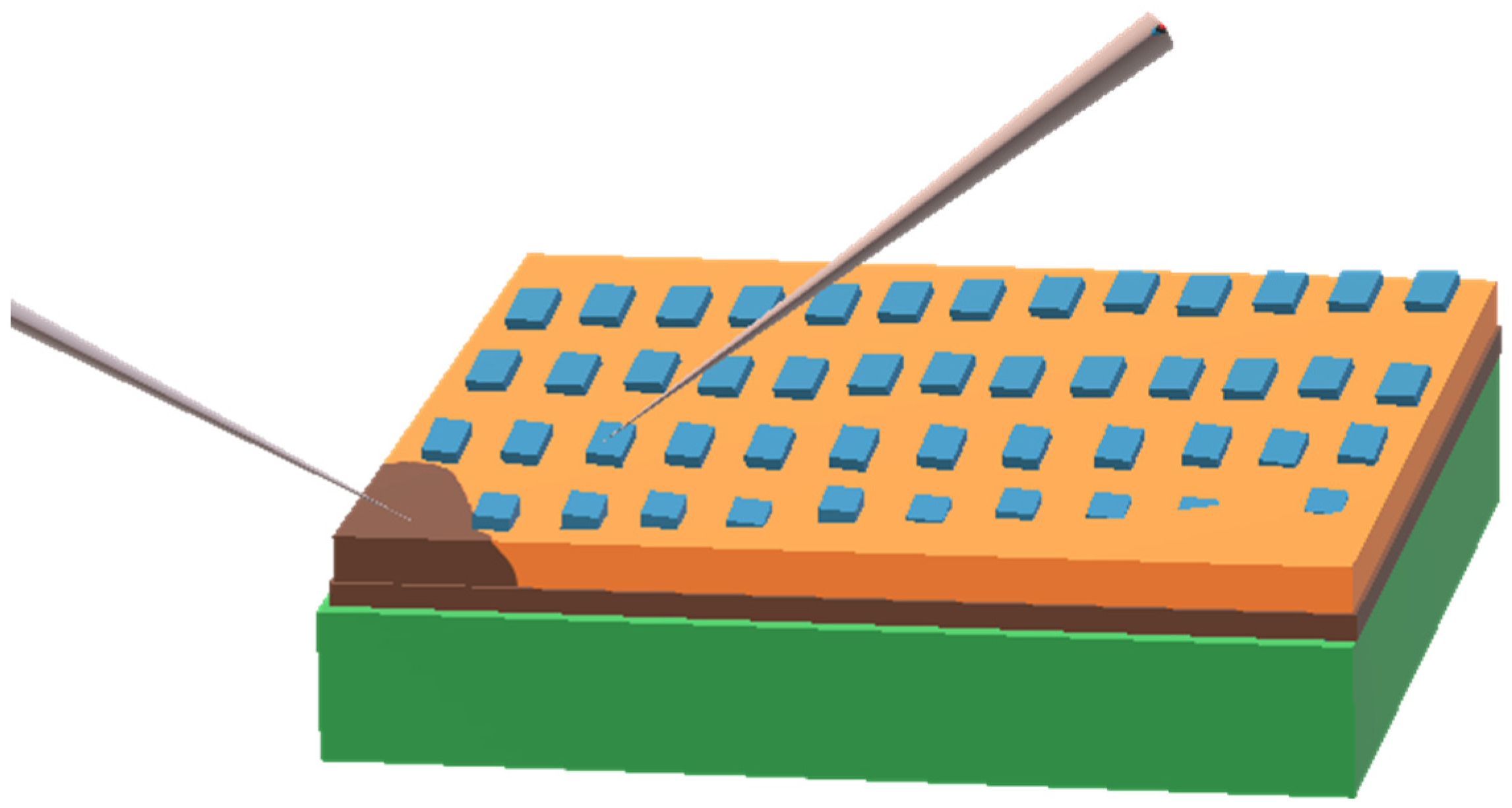
For the magnetic measurements, the PZTFT layer was deposited on a MgO (100) substrate using the same deposition conditions. The thickness of the PZTFTx thin films was around ~300 nm, obtained from an analysis of the films’ height profiles, which were measured using a XP-200 Profilometer. Employing AFM-Veeco Atomic Force Microscopy, the in-plane morphology was measured from a 5 × 5 μm2 area of the thin films. The crystallographic phase purity and the orientation of the thin films were studied from an analysis of high-resolution X-ray diffraction (XRD) data which were recorded using a Rigaku Ultima III x-ray diffractometer using a Cu-Kα radiation (λ = 1.5405 Å). The XRD diffractometer was equipped with Cu-Kα radiation (Kα = 1.5405 Å) configured in Bragg–Brentano (θ–2θ) geometry, and it was operated at 40 kV and 44 mA. The PZTFTx capacitors were fabricated by sandwiching ferroelectric capacitors between the conducting bottom LSCO layer and the top platinum (Pt) electrode to carry out dielectric spectroscopic and ferroelectric measurements. The fabrication of the top Pt electrodes was carried out via D.C. sputtering using a silver metal shadow mask of an area of 10−8 m2, an Ar gas partial pressure of 15 mTorr, and a power of 40 Watt. The electrodes were then annealed at 473 K in an oxygen atmosphere for 30 min to compensate for any defects caused during the sputtering process. For clarity, a schematic diagram of the ferroelectric capacitors sandwiched between the top platinum electrode and the bottom LSCO conducting layer is shown (Scheme 1). Ferroelectric hysteresis loops were measured at room temperature at different frequencies, using a hysteresis loop tester (radiant Technologies RT6000 HVS). Magnetic characterizations were obtained by employing a Quantum Design MPMS XL-7 SQUID magnetometer in a range of temperatures from 15 to 300 K. The magnetoelectric voltage coefficients of these thin-film capacitors were obtained via the dynamic method by measuring the voltage across the films in a lock-in-amplifier set up. The bias magnetic field was an ac field of 0.5 Oe with a frequency of 1 kHz. It should be noted that the thin films were deposited in an optimized oxygen partial pressure of 300 mTorr; following deposition, the films were annealed in a 300 Torr oxygen atmosphere (Table 1) to compensate for any oxygen defects formed during the deposition process. Therefore, the ferroelectric and magnetic results from the materials are mainly from the stoichiometric PZTFTx thin films. However, as expected, minimal contributions to the ferroic orderings from point defects and strain cannot be neglected.

Scheme 1.
Schematic: PZTFTx ferroelectric capacitors sandwiched between the top platinum electrode and the bottom LSCO conducting layer.
3. Results and Discussion
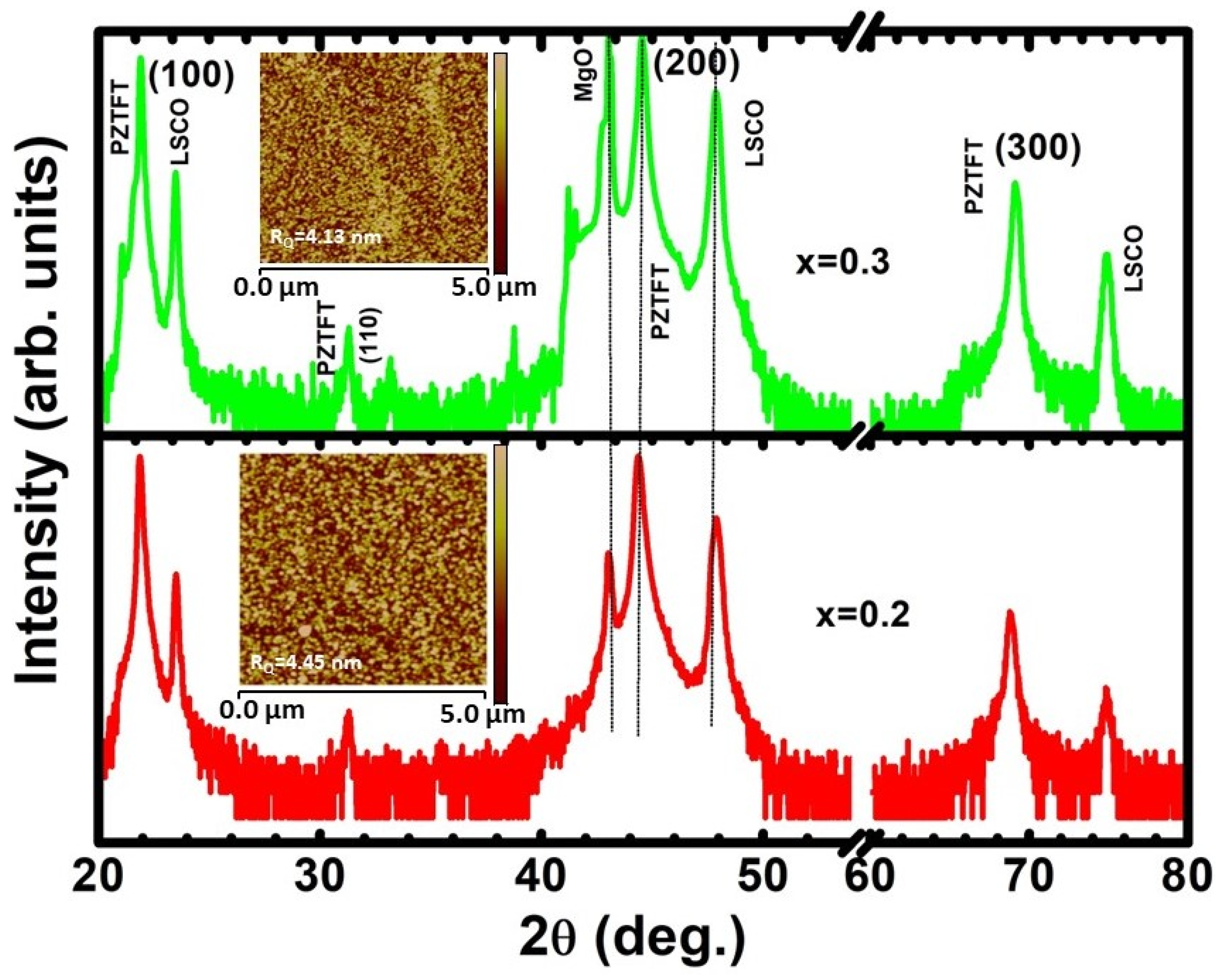
Figure 1 shows the room temperature X-ray diffraction (XRD) pattern of the PZTFTx/LSCO/MgO thin films measured in a 2θ range from 20 to 80 °. The sharp reflection peaks of the diffraction pattern suggest the crystalline nature of the grown thin films. The structure of the PZTFTx thin films was determined from an analysis of the XRD data. These thin films are in a single phase and stabilized in the orthorhombic phase [12], with nearly (100) orientations. Though weak in intensity, the appearance of a (110) reflection peak in the diffraction pattern is discernable. The relative volume of the (110)-oriented phase was estimated to be 0.09% and 0.03% for x = 0.2 and 0.3, respectively. The peak positions were found to slightly shift towards a higher 2θ angle with an increase in x, indicating a reduction in the unit cell volume due to the substitution of the small ionic radii of the Fe and Ta cations. Using POWD software, for x = 0.2, the in-plane orthorhombic lattice parameters a = 4.0438(1) Å and b = 4.0672(1) Å were obtained; the parameters for x = 0.3 are: a = 4.0882(2) Å and b = 4.0698(2) Å. Lattice mismatches among the substrate, buffer conducting layer, and film often build strain in thin films [18]. The lattice strain η in a thin film can be evaluated using the formulation [18] η = (abulk – afilm/afilm) × 100, where η is the lattice strain and abulk and afilm are the lattice constants of bulk and film, respectively. The lattice parameters of the bulk and thin films were considered to estimate the in-plane strain in the films. The thin films x = 0.2 and 0.3 have in-plane compressive strain values of 0.22% and 0.04%, respectively. Hence, in the x = 0.3 thin films, a small amount of strain is found. Atomic force micrographs were obtained on a plane surface area of 5 × 5 µm2 on the thin films, operating in contact mode on a z-scale of 20 nm (inset in Figure 1). The roughness Rq (root-mean-square) of the films obtained from the analysis of the AFM images ranges from 4 to 5 nm. This indicates a homogeneous distribution of grains on the thin films which resulted in a smooth surface.
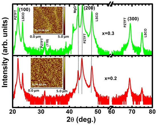
Figure 1.
X-ray diffraction patterns at ambient temperature for the PZTFTx/LSCO/MgO thin films. Inset: Atomic force micrograph from an area of 5 × 5 μm2 and a 20 nm z-scale.
The temperature-dependent dielectric constant εr and the loss tangent tan δ of the thin-film capacitors were measured from 100 to 600 K in intervals of 10 K in the frequency range of 102–105 Hz, as depicted in Figure 2a,b. It can be observed that with an increasing temperature, the dielectric constant increased slowly up to 400 K, then exhibited a rapid rise to its maximum value at Tm~560 K and 520 K for the x = 0.2 and 0.3 thin films, respectively; it subsequently decreased at high temperatures. The dielectric constant εr broadened over a wider temperature range from 400 to 600 K due to the statistical distribution of relaxation times in that temperature window. This indicates that the materials exhibited a diffuse ferroelectric phase transition (DPT) at elevated temperatures [24,25,26,27]. The variation in the loss tangent (tan δ) with temperature was almost flat from 100 to 400 K and increased suddenly with an increasing temperature above 400 K. As the mobility of oxygen vacancies increases at high temperatures, one can expect their contribution to ionic conductivity to occur in thin-film capacitors above 400 K. Hence, the increasing trend of the loss tangent above 400 K can be attributed to the contribution from ionic conductivity [26,28,29]. The dielectric constant εr as a function of temperature (at 10 kHz) was analyzed (Figure 2c,d) to obtain insight into the behavior of the phase transition. The Curie–Weiss law is expressed as [29,30] , where C corresponds to the Curie–Weiss constant, and Tm represents the temperature at which the dielectric maximum εm is observed. As can be seen, the dielectric constant began to exhibit nonlinear behavior at Tcw. The difference in temperature ΔTm = Tcw − Tm provides information about how much the material’s Curie–Weiss ferroelectric behavior deviates [29]. The ΔTm values of 30 K (x = 0.2) and 40 K (x = 0.3) were obtained, suggesting that the PZTFT films exhibited a diffused ferroelectric phase transition at elevated temperatures. The fitted parameters C, Tcw, and ΔTm, which were obtained from the dielectric analysis, are presented in Table 2. A reduction in the dielectric maximum temperature Tm and an increase in the ΔTm value for the x = 0.3 thin films compared to the x = 0.2 thin films are observed, consistent with earlier reports on PZTFT ceramics [12]. The variation in the dielectric permittivity with respect to temperature was analyzed using a modified Curie–Weiss law to gain insight into the diffusivity of ferroelectricity. The expression for the modified Curie–Weiss law is [31,32,33] where c1 corresponds to a constant and the exponent γ represents the diffusivity parameter of the broad ferroelectric transition. To be precise, γ = 1 corresponds to a normal ferroelectric transition and γ = 2 corresponds to a total diffuse ferroelectric transition. On the other hand, the range of values 1 ≤ γ ≤ 2 represents an incomplete diffuse ferroelectric transition [24]. To perform this exercise, dielectric data at 10 kHz above the dielectric maximum temperature Tm were considered. The slope values calculated from the plot of versus fitted line were found to be γ = 1.93 and 1.95 for x = 0.2 and 0.3, respectively (inset: Figure 2c,d). The value of the diffusivity parameter found in the 1 < γ < 2 range indicates that both the nanostructured thin films underwent a diffuse ferroelectric phase transition at a high temperature. In an earlier study on PZTFTx ceramics [12], the temperature corresponding to the dielectric maximum εm observed in the thin films for x = 0.3 is almost the same, suggesting that negligible lattice strain is involved in the PZTFTx thin films, which is corroborated by the XRD study. Therefore, a weak polarization–strain quadratic coupling in the thin films is evident and is probably the reason for the nearly identical ferroelectric phase transition temperatures of the reported ceramics and our thin films [12].
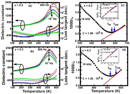
Figure 2.
Dielectric constant (εr) and loss tangent (tan δ) of PZTFTx thin-film capacitors measured from 100 to 650 K at several frequencies: (a) x = 0.2; (b) x = 0.3. The reciprocal dielectric constant (1000/εr) versus the temperature of the thin films measured at 10 kHz: (c) x = 0.2; (d) x = 0.3. The respective versus plots are shown as insets.
Table 2.
The fitted parameters obtained from an analysis of the dielectric data at 10 kHz.
Room-temperature ferroelectric hysteresis loops were recorded from the PZTFTx thin-film capacitors with different electric fields from 0 to 600 kV/cm at several frequencies, using a Radiant hysteresis-loop-tester device (Figure 3a,b). The electric polarization increased with an increase in the electric field from 0 to ~400 kV/cm and was saturated at around 400 kV/cm. As can be seen, the ferroelectric hysteresis loops were well-saturated with large remanent (Pr) and saturation polarizations (Ps), suggesting the intrinsic ferroelectric behavior of the materials. For instance, for the x = 0.2 thin films, the Pr and Ps values were 76 and 93 μC/cm2, respectively; for x = 0.3, the Pr and Ps values were 74 and 91 μC/cm2, respectively. In these thin-film capacitors, the coercive field (Ec) values were 130 kV/cm (for x = 0.2) and 98 kV/cm (for x = 0.3). In the PZTFTx ceramic capacitors with x = 0.3, the reported remanent Pr and saturated polarization Ps were ~15 μC/cm2 and ~25 μC/cm2 [12]. One can observe imprint phenomena in these P-E loops since the top platinum and bottom LSCO electrodes have separate work functions that generate an effective internal electric field. Pt/PZT/LSCO thin-film capacitors showed such an imprint behavior earlier [34,35]. The imprinting effect is related to the issue of reliability in FE memory because the relocate field is rather large; therefore, the two logic states, +Pr and −Pr, can become indistinguishable during memory reading. However, this issue can be ignored in our PZTFTx thin-film capacitors due to the high remanent polarization (Pr) values involved in the preference states. A plot of capacitance (C) versus the applied bias voltage (V) is shown (inset: Figure 3a,b). One can observe a double peak in the C versus V curves, and the capacitive maxima are located close to the coercive fields. In addition, the hysteresis field width involved in these dielectric peaks shows the characteristic properties of a ferroelectric capacitor [36]. The observed maxima in the C-V curves are possibly due to the contributions of a maximum number of domain wall motions in the vicinity of the coercive field in the films [36,37]. We carried out a detailed ferroelectric study of the system carefully and repeated the measurements with different capacitors in the thin films, producing almost the same results. To check whether the polarization behavior of the capacitors depended on frequency or not, the ferroelectric polarization of PZTFTx was also measured at a frequency of 50 Hz (Figure 3c,d). The dependence of the polarization behaviors on frequency was found to be weak. For instance, the observed decrease in Pr from 76 to 72 μC/cm2 in x = 0.2 and from 74 to 71 μC/cm2 in x = 0.3 is evident while considering the frequency from 10 kHz to 50 Hz (Figure 3). This weak frequency dependence of the polarization behavior indicates negligible contributions from oxygen vacancy (leakage current) and nonlinear dielectricity [38]. The coercivity Ec was found to decrease slightly with a decrease in the frequency, which could be due to the single-switching dynamic followed by the ferroelectrics [39].
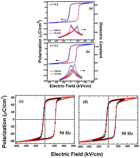
Figure 3.
Ferroelectric hysteresis loops and dielectric constants measured as functions of the electric field for PZTFTx thin-film capacitors at an ambient temperature for frequencies of 100 Hz and 10 kHz (a) x = 0.2; and (b) x = 0.3. Room-temperature P-E hysteresis loops of the PZTFTx thin-film capacitors measured at 50 Hz: (c) x = 0.2; and (d) x = 0.3.
Oxygen stoichiometry is one key factor in determining the magnetic properties of oxides. As mentioned previously, PZTFT thin films were grown and annealed in an oxygen atmosphere; therefore, one can expect a minimal oxygen deficiency in these thin films. To study the behavior of the magnetic ordering in the PZTFTx films, magnetization M hysteresis loops were measured in the magnetic field H in the range of ±70 kOe (in-plane field) at several temperatures from 15 to 300 K. The temperature-dependent magnetization loops for the x = 0.2 and x = 0.3 thin films are shown in Figure 4, which shows discernable, square-shaped magnetic hysteresis loops with saturated magnetization Ms values above 16 kOe, indicating the ferri-/ferromagnetic behavior of the films from 15 to 300 K. In the low magnetic field, the magnetization growth increased and was saturated at a high magnetic field above 16 kOe. Reductions in both the remanent and coercive fields of the M-H magnetization loops are evident with increasing temperatures. For clarity, the zoomed-out M-H magnetization loops seen in the low field (<1 kOe) region are shown as insets in Figure 4. For x = 0.2, at 15 K, the remanent Mr was observed to be 1.3 emu/cm3, and the coercive field Hc was 270 Oe. With the rising temperature, these values continuously decreased to 0.5 emu/cm3 and 160 Oe at 300 K. Similarly, for x = 0.3, at 15 K, the remanent Mr was found to be 2.3 emu/cm3, and the coercive field Hc was 260 Oe. Furthermore, these reduced to Mr ~0.5 emu/cm3 and Hc ~110 Oe at 300 K. Thus, these thin films exhibited ferromagnetic ordering from 15 K to 300 K. Such ferromagnetic behavior was reported in bulk PZTFTx. [12,20] and PZTFT0.4 thin films [18]. The ferromagnetic ordering in these material is inferred through the Fe3+-O-Fe3+ super-exchange ionic interaction established in the material [12,18]. It should be noted that there was a sharp decrease in magnetization after 15 K (Figure 4). The original PbFe0.5Ta0.5O3 (PFT) underwent two anti-ferromagnetic transitions that took place at about 150 K and 9 K [18]. Therefore, the Neel temperature TN related to the PFT can be attributed to this observed anomaly in magnetization. At present, we do not have magnetization data in a closer interval in the range of 15–50 K. A close inspection of the temperature-dependent magnetization data (<50 K) measured in a closer T-interval will be helpful for attaining more clarity about the present observations.
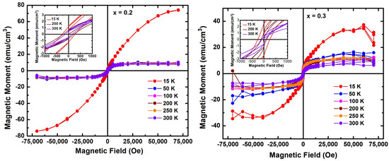
Figure 4.
Magnetization hysteresis loops recorded from 15 to 300 K. Inset: Zoomed-in view of the magnetization loops in a low field range of ±1000 Oe.
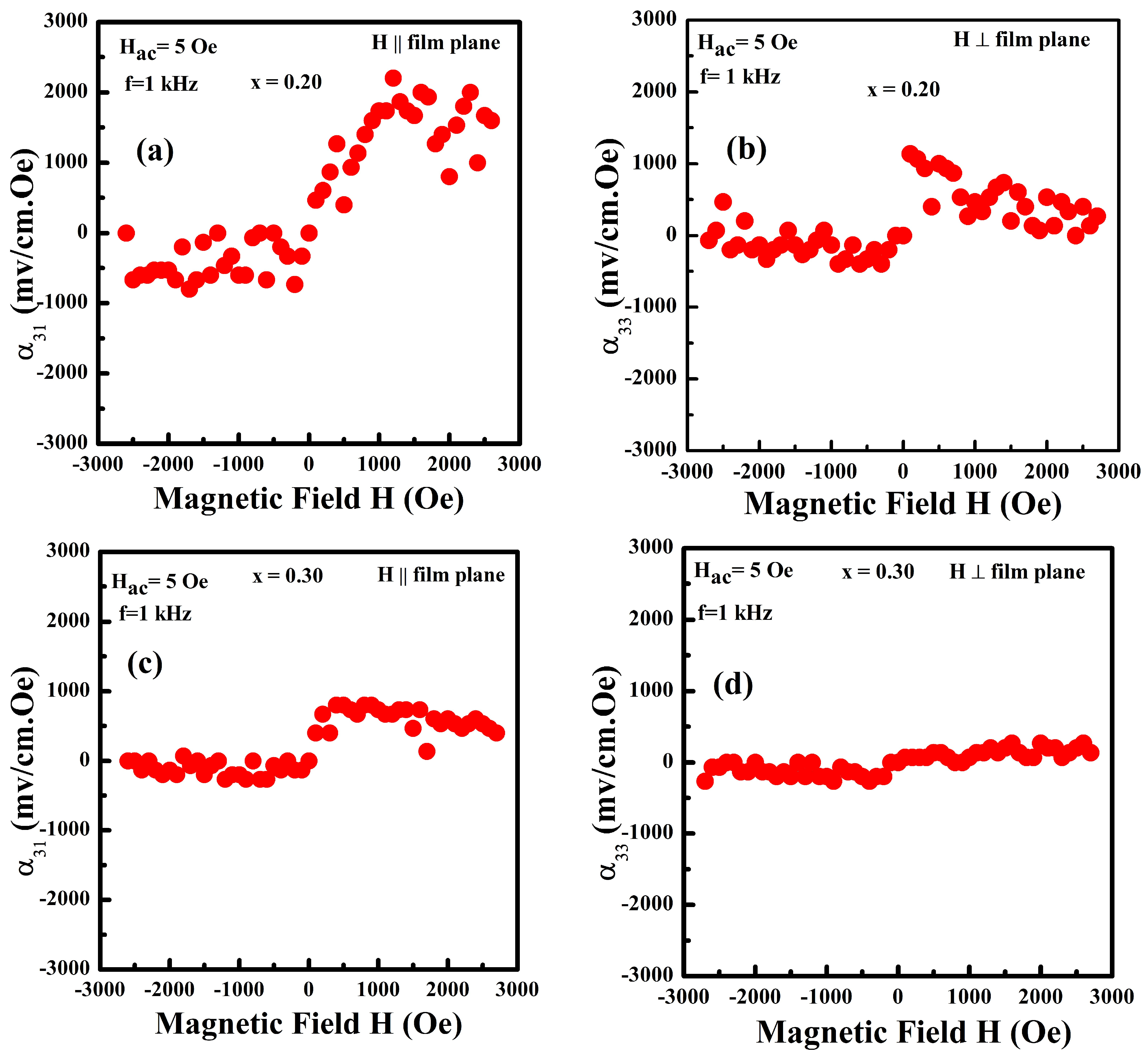
The room-temperature magnetoelectric interactions in the PZTFTx films were measured by applying a magnetic field across the thin films. The results illustrate the direct interaction between the ferroelectric and magnetic orderings in the films. To be precise, the results of the magnetoelectric voltage coefficient αME were measured across the thin films sandwiched between an LSCO bottom and a Pt top electrode, employing the dynamic method (Figure 5). The αME coefficient, the dimensional parameters of the sample, and the applied magnetic field are related as αME = αV/αH (1/d), where αV, αH, and d represent the output voltage, the applied ac magnetic field, and the thickness of the thin films, respectively. The αME coefficient was estimated using this expression. A bias magnetic field from 0 to 2600 Oe was applied across the thin films at a step size of 100 Oe to measure the output voltage αME of the thin films. Throughout the measurement, the ac magnetic field was 5 Oe with frequency of 1 kHz. The x = 0.2 thin films possessed a high value of αME = 2040 mV/cm.Oe at a bias magnetic field of 1660 Oe (in-plane). Then αME value decreased gradually with an increase in the magnetic field from 1660 to 2600 Oe (Figure 5a). On the other hand, the αME was found to be small for the application of the bias field in the cross-plane mode. The maximum αME value of about 1044 mV/cm.Oe was obtained at a bias field of 205 Oe (out-of-plane). The αME was measured in the bias field range from 200 to 2600 Oe. A gradual change in the αME value from 200 Oe to the maximum field of 2600 Oe was noticed. At a bias field of 2600 Oe, the αME turned out to be 250 mV/cm.Oe. Similarly, for the other thin film composition (x = 0.3) (Figure 5b), the largest αME values were obtained as 850 mV/cm.Oe at a bias field (in-plane) of 500 Oe and 271 mV/cm.Oe at a bias field (out-of-plane) of 1570 Oe. The reductions in the MEVC values under the out-of-plane bias field in both compositions are due to the demagnetization correlated with the bias and the ac magnetic field. The large of αME value obtained from these thin films under an in-plane bias field is due to the epitaxial nature, large ferroelectric polarization values, and reasonably good magnetic ordering of the thin films at room temperature [2,40,41,42]. The room-temperature ME coupling observed in our nanostructured thin films is significantly large compared to the αME values reported in several materials such as PZTFTx ceramics (x = 0.2, αME = 12mV/cm.Oe), ref. [20] thin films consisting of three alternate layers of Pb(Fe0.5Nb0.5)O3 and Ni0.65Zn0.35FeO4 (αME = 383 mV/cm.Oe) [28], thin films consisting of two layers of BiFeO3 and BaTiO3 (αME = 61 mV/cm.Oe) [43], etc. Hence, these thin films are candidate materials for application in spintronic and magnetic storage devices. The ME coupling αME curves measured with respect to bias fields of the opposite polarity did not follow the same path and were slightly asymmetric. This asymmetric behavior can be attributed to magnetic anisotropy and the interface effect [28]. The magnetoelectric coupling in these thin films could be due to the magnetostriction effect generated by a change in magnetic ordering due to alterations in the bias field. The strain produced from magnetostriction caused a change in the ferroelectric ordering of the films [2,40,41,44,45,46], resulting in the establishment of a magnetoelectric output voltage (αV), which was measured experimentally. The values of the dielectric constant, ferroelectric, magnetic ordering, and magnetoelectric coefficient in the x = 0.2 thin films were found to be large compared to the x = 0.3 thin films. Upon increasing the magnetic Fe cation content in the PZTFT, the ferroelectric ordering was diluted, as can be seen in Figure 2 and Figure 3. Although one could expect a large magnetization in the x = 0.3 thin films due to a higher concentration of magnetic ions, was not observed experimentally. The possible reason for the large magnetic moment and the hysteresis behavior in the x = 0.2 thin films could be due to the strain state involved in these films [23]. The ferroelectric polarization and dielectric susceptibility of the ferroelectric phase in the x = 0.2 films can also receive a contribution from lattice strain and thus probably the observed improved ferroelectric behavior in these films. On the other hand, the x = 0.3 thin film showed negligible strain, suggesting that the magnetic ordering mainly received a contribution from the distribution of Fe ions. The use of the first principles and phenomenological calculations are underway to understand the exact mechanism behind the robust ferroelectric, magnetic ordering, and large magnetoelectric voltage coefficient in the x = 0.2 films. These results will be discussed in a subsequent publication.
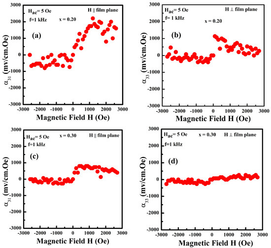
Figure 5.
Room-temperature magnetoelectric voltage coefficient αME values versus the bias field H in the x = 0.2 film’s (a) in-plane field and (b) cross-plane field and in the x = 0.3 film’s (c) in-plane field and (d) cross-plane field.
4. Conclusions
In summary, nearly 100-oriented PZTFTx thin films of a thickness of around 300 nm were grown on LSCO-electrode-buffered MgO substrates using a pulsed laser deposition chamber in a controlled oxygen atmosphere. The thin films were impurity-free and phase-pure; they were stabilized in an orthorhombic phase. Dielectric spectroscopic studies on the thin-film capacitors identified a diffuse ferroelectric-to-paraelectric phase transition at a high temperature. The ferroelectric polarization loops (P-E loops) of the thin-film capacitors were well-saturated with high saturation (Ps) and remanent (Pr) polarizations, confirming the establishment of ferroelectric ordering in these films. The square-shaped M-H hysteresis loops measured in these materials indicated a ferro/ferrimagnetic ordering in the films up to room temperature (15–300 K). At room temperature, the magnetoelectric coupling constant αME measured on the PZTFTx thin-film capacitors showed values as large as 2040 mV/cm.Oe (x = 0.2) and 850 mV/cm Oe (x = 0.3). The possible reason for the large magnetic moment and the hysteresis behavior in the x = 0.2 thin films is attributed to the strain state involved in the films. The nanostructured PZTFTx thin films exhibited large dielectric constants, low loss tangents, large saturation polarization values, and large magnetoelectric coupling. These thin films are magnetoelectric multiferroic at room temperature and may have potential applications in multifunctional devices and spintronics applications.
Author Contributions
D.A.S. synthesized and characterized the samples, the analysis of the data was conducted by D.A.S. and K.K.M., and the manuscript was prepared by K.K.M. Magnetoelectric coefficient measurements were performed at Oakland University, Rochester, USA, by S.S. and G.S., and R.S.K. and K.K.M. supervised the progress of the research work. All authors have read and agreed to the published version of the manuscript.
Funding
This work was financially supported by the Air Force Office of Scientific Research (AFOSR), Award No. FA9550-20-1-0064. The investigation carried out at Oakland University was supported by grants from the National Science Foundation (DMR-1808892, ECCS-1923732, ECCS-EAGER-2236879) and the Air Force Office of Scientific Research (AFOSR), Award No. FA9550-20-1-0114.
Institutional Review Board Statement
Not applicable.
Informed Consent Statement
Not applicable.
Data Availability Statement
The data sets are available from the corresponding author upon reasonable request.
Conflicts of Interest
The authors declare no conflict of interest.
References
- Kimura, T.; Goto, T.; Shintani, H.; Ishizaka, K.; Arima, T.; Tokura, Y. Magnetic control of ferroelectric polarization. Nature 2003, 426, 55–58. [Google Scholar] [CrossRef]
- Eerenstein, W.; Mathur, N.D.; Scott, J.F. Multiferroic and magnetoelectric materials. Nature 2006, 422, 759–765. [Google Scholar] [CrossRef] [PubMed]
- Tokura, Y.; Seki, S.; Nagaosa, N. Multiferroics of spin origin. Rep. Prog. Phys. 2014, 77, 076501. [Google Scholar] [CrossRef] [PubMed]
- Ohno, H.; Chiba, D.; Matsukura, F.; Omiya, T.; Abe, E.; Dietl, T.; Ohno, Y.; Ohtani, K. Electric-field control of ferromagnetism. Nature 2000, 408, 944–946. [Google Scholar] [CrossRef] [PubMed]
- Prellier, W.; Singh, M.P.; Murugavel, P. The single-phase multiferroic oxides: From bulk to thin film. J. Phys. Condens. Matter. 2005, 17, R803. [Google Scholar] [CrossRef]
- Hill, N.A. Why Are There So Few Magnetic Ferroelectrics? J. Phys. Chem. B 2000, 104, 6694–6709. [Google Scholar] [CrossRef]
- Wang, J.; Neaton, J.B.; Zheng, H.; Nagarajan, V.; Ogale, S.B.; Liu, B.; Viehland, D.; Vaithyanathan, V.; Schlom, D.G.; Waghmare, U.V.; et al. Epitaxial BiFeO3 Multiferroic Thin Film Heterostructures. Science 2003, 299, 1719–1722. [Google Scholar] [CrossRef]
- Song, S.; Jang, H.M.; Lee, N.-S.; Son, J.Y.; Gupta, R.; Garg, A.; Ratanapreechachai, J.; Scott, J.F. Ferroelectric polarization switching with a remarkably high activation energy in orthorhombic GaFeO3 thin films. NPG Asia Mater. 2016, 8, e242. [Google Scholar] [CrossRef]
- Mishra, K.K.; Hernandez, J.A.; Instan, A.A.; McCartan, S.J.; Gregg, M.; Katiyar, R.S. Lead palladium zirconate titanate: A room temperature nanoscale multiferroic thin film. J. Appl. Phys. 2020, 127, 204104. [Google Scholar] [CrossRef]
- Kumari, S.; Pradhan, D.K.; Ortega, N.; Pradhan, K.; DeVreugd, C.; Srinivasan, G.; Kumar, A.; Paudel, T.R.; Tsymbal, E.Y.; Bumstead, A.M.; et al. Palladium-based ferroelectrics and multiferroics: Theory and experiment. Phys. Rev. B 2017, 95, 214109. [Google Scholar] [CrossRef]
- Evans, D.M.; Schilling, A.; Kumar, A.; Sanchez, D.; Ortega, N.; Arredondo, M.; Katiyar, R.S.; Gregg, J.M.; Scott, J.F. Magnetic switching of ferroelectric domains at room temperature in multiferroic PZTFT. Nat. Commun. 2013, 4, 1534. [Google Scholar] [CrossRef] [PubMed]
- Sanchez, D.; Ortega, N.; Kumar, A.S.; Roque-Malherbe, R.M.A.; Polanco, R.; Scott, J.F.; Katiyar, R.S. Symmetries and multiferroic properties of novel room-temperature magnetoelectrics: Lead iron tantalate-lead zirconate titanate (PFT/PZT). AIP Adv. 2011, 1, 042169. [Google Scholar] [CrossRef]
- Gonnard, P.; Troccaz, M. Dopant distribution between A and B sites in the PZT ceramics of type ABO3. J. Solid State Chem. 1978, 23, 321–326. [Google Scholar] [CrossRef]
- Fernandes, J.R.A.; Joanni, E.; Savu, R. Optimization of the Fabrication Parameters of PZT 52/48 Thin Films by Pulsed Laser Ablation. Mater. Sci. Forum 2006, 514–516, 1353–1357. [Google Scholar] [CrossRef]
- Jaffe, B.; Roth, R.S.; Marzullo, S. Piezoelectric properties of lead zirconate-leadtitanate solid-solution ceramics. J. Appl. Phys. 1954, 25, 809–810. [Google Scholar] [CrossRef]
- Noheda, B.; Gonzalo, J.A.; Cross, L.E.; Gou, R.; Park, S.-E.; Cox, D.E.; Shirane, G. Tetragonal-to-monoclinic phase transition in a ferroelectric perovskite: The structure of PbZr0.52Ti0.48O3. Phys. Rev. B 2000, 61, 8687. [Google Scholar] [CrossRef]
- Levstik, A.; Bobnar, V.; Filipic, C.; Holc, J.; Kosec, M.; Blinc, R.; Trontel, Z.; Jaglicic, Z. Magnetoelectric relaxor. Appl. Phys. Lett. 2007, 91, 012905. [Google Scholar] [CrossRef]
- Sanchez, D.A.; Kumar, A.; Ortega, N.; Katiyar, R.S.; Scott, J.F. Near-room temperature relaxor multiferroic. Appl. Phys. Lett. 2010, 97, 202910. [Google Scholar] [CrossRef]
- Wu, Y.-C.; Ho, S.Z.; Liu, Y.C.; Liou, Y.-D.; Liu, W.-Y.; Huang, S.-W.; Jiang, J.; Chen, Y.-C.; Yang, J.-C. Room Temperature Multiferroic PZTFT Thin Films. ACS Appl. Electron. Mater. 2020, 2, 19–24. [Google Scholar] [CrossRef]
- Sanchez, D.A.; Ortega, N.; Kumar, A.; Sreenivasulu, G.; Katiyar, R.S.; Scott, J.F.; Evans, D.M.; Arredondo-Arechavala, M.; Schilling, A.; Gregg, J.M. Room-temperature single phase multiferroic magnetoelectric: Pb(Fe, M)x(Zr,Ti)(1−x)O3[M = Ta, Nb]. J. Appl. Phys. 2013, 113, 074105. [Google Scholar] [CrossRef]
- Eerenstein, W.; Morrison, F.D.; Dho, J.; Blamire, M.G.; Scott, J.F.; Mathur, N.D. Comment on Epitaxial BiFeO3 multiferroic thin film heterostructures. Science 2005, 307, 1203. [Google Scholar] [CrossRef] [PubMed]
- Fiebig, M. Revival of the Magnetoelectric Effect. J. Phys. D Appl. Phys. 2005, 38, R123. [Google Scholar] [CrossRef]
- Goto, T.; Kim, D.H.; Sun, X.; Onbasli, M.C.; Florez, J.M.; Ong, S.P.; Vargas, P.; Ackland, K.; Stamenov, P.; Aimon, N.M.; et al. Magnetism and Faraday Rotation in Oxygen-Deficient Polycrystalline and Single-Crystal Iron-Substituted Strontium Titanate. Phys. Rev. Appl. 2017, 7, 024006. [Google Scholar] [CrossRef]
- Florez, J.M.; Solis, M.A.; Corte, E.A.; Morell, E.S.; Ross, C.A. First-principles based Monte Carlo modeling of the magnetization of oxygen-deficient Fe-substituted SrTiO3. Phys. Chem. Chem. Phys. 2023, 25, 19214. [Google Scholar] [CrossRef]
- Bajpai, P.K.; Pastor, M.; Singh, K.N. Diffuse Phase Transition and Electrical Conductivity of Pb(Ca1/3Nb2/3)O3. J. Electron. Mater. 2014, 43, 1403–1410. [Google Scholar] [CrossRef]
- Boukamp, B.A.; Pham, M.T.N.; Blank, D.H.A.; Bouwmeester, H.J.M. Inonic and electronic conductivity in lead-zirconate-titanate (PZT). Solid State Ionics. 2004, 170, 239. [Google Scholar] [CrossRef]
- Kleemann, W.; Shvartsman, V.; Borisov, P.; Kania, A. Coexistence of Antiferromagnetic and Spin Cluster Glass in the Magnetoelectric Relaxor Multiferroic PbFe0.5Nb0.5O3. Phys. Rev. Lett. 2010, 105, 257202–257204. [Google Scholar] [CrossRef] [PubMed]
- Pradhan, D.K.; Kumari, S.; Vasudevan, R.K.; Strelcov, E.; Puli, V.S.; Pradhan, D.K.; Kumar, A.; Gregg, J.M.; Pradhan, A.K.; Kalinin, S.V.; et al. Exploring the Magnetoelectric Coupling at the Composite Interfaces of FE/FM/FE Heterostructures. Sci. Rep. 2018, 8, 17381. [Google Scholar] [CrossRef]
- Yu, Z.; Guo, R.; Bhalla, A.S. Dielectric behavior of Ba(Ti1−xZrx)O3 single crystals. J. Appl. Phys. 2000, 88, 410–415. [Google Scholar] [CrossRef]
- Moquim, A.; Panigrahi, M.R. Phase transition and relaxor nature of (Ba0.77Ca0.23)(Ti0.98La0.02)O3 ceramic prepared by mixed oxide route. J. Mater. Sci. Mater. Electron. 2015, 26, 4956–4962. [Google Scholar] [CrossRef]
- M’Peko, J.C.; Peixoto, A.G.; Jimenez, E.; Gaggero-Sager, L.M. Electrical Properties of Nb-Doped PZT 65/35 Ceramics: Influence of Nb and Excess PbO. J. Electroceram. 2005, 15, 167–176. [Google Scholar] [CrossRef]
- Zhang, T.-F.; Huang, X.-X.; Tang, X.-G.; Jiang, Y.-P.; Liu, Q.-X.; Lu, B.; Lu, S.-G. Enhanced electrocaloric analysis and energy-storage performance of lanthanum modified lead titanate ceramics for potential solid-state refrigeration applications. Sci. Rep. 2018, 8, 396. [Google Scholar] [CrossRef]
- Diez-betriu, X.; Garcia, J.E.; Ostos, C.; Boya, A.U.; Ochoa, D.A.; Mestres, L.; Perez, R. Phase transition characteristics and dielectric properties of rare-earth (La, Pr, Nd, Gd) doped Ba(Zr0.09Ti0.91)O3 ceramics. Mater. Chem. Phys. 2011, 125, 493–499. [Google Scholar] [CrossRef]
- Tomas, R.; Mochizuki, S.; Mihara, T.; Ishida, T. Perovskite crystallization of sol-gel processed (Pb, La0.06, Gd0.02)(Zr0.65,Ti0.35)O3 thin films: Dielectric, ferroelectric and optical properties. J. Mater. Res. 2002, 17, 2652–2659. [Google Scholar] [CrossRef]
- Lee, J.; Ramesh, R. Imprint of (Pb,La)(Zr,Ti)O3 thin films with various crystalline qualities. Appl. Phys. Lett. 1996, 68, 484–486. [Google Scholar] [CrossRef]
- Bolten, D.; Lohse, O.; Grossmann, M.; Waser, R. Reversible and irreversible domain wall contributions to the polarization in ferroelectric thin films. Ferroelectrics 1999, 221, 251–257. [Google Scholar] [CrossRef]
- Sharma, Y.; Barrionuevo, D.; Agarwal, R.; Pavunny, S.P.; Katiyar, R.S. Ferroelectricity in Rare-Earth Modified Hafnia Thin Films Deposited by Sequential Pulsed Laser Deposition. ECS Solid State Lett. 2015, 4, N13–N16. [Google Scholar] [CrossRef]
- Liu, W.-Y.; Liao, J.-J.; Jiang, J.; Zhou, Y.-C.; Chen, Q.; Mo, S.-T.; Yang, Q.; Peng, Q.-X.; Jiang, L.-M. Highly stable performance of flexible Hf0.6Zr0.4O2 ferroelectric thin films under multi-service conditions. J. Mater. Chem. C 2020, 8, 3878. [Google Scholar] [CrossRef]
- Hu, W.J.; Juo, D.-M.; You, L.; Wang, J.; Chen, Y.-C.; Chu, Y.-H.; Wu, T. Universal Ferroelectric Switching Dynamics of Vinylidene Fluoride-trifluoroethylene Copolymer Film. Sci. Rep. 2014, 4, 4772. [Google Scholar] [CrossRef]
- Wang, Y.; Hu, J.; Lin, Y.; Nan, C.-W. Multiferroic Magnetoelectric Composite Nanostructures. NPG Asia Mater. 2014, 4, 4772. [Google Scholar] [CrossRef]
- Ma, J.; Hu, J.; Li, Z.; Nan, C.-W. Recent Progress in Multiferroic Magnetoelectric Composites: From Bulk to Thin Films. Adv. Mater. 2011, 23, 1062–1087. [Google Scholar] [CrossRef] [PubMed]
- Hu, J.-M.; Nan, C.-W.; Chen, L.-Q. Size-dependent electric voltage controlled magnetic anisotropy in multiferroic heterostructures: Interface-charge and strain co-mediated magnetoelectric coupling. Phys. Rev. B 2011, 83, 134408. [Google Scholar] [CrossRef]
- Gupta, R.; Chaudhary, S.; Kotnala, R.K. Interfacial Charge Induced Magnetoelectric Coupling at BiFeO3/BaTiO3 Bilayer Interface. ACS Appl. Mater. Interfaces 2015, 7, 8472–8479. [Google Scholar] [CrossRef] [PubMed]
- Kulikowski, J.; Bienkowski, A. Magnetostrictive properties of Cox(NiZn)1−xFe2O4 ferrites in the case of small changes of iron content. J. Magn. Magn. Mater. 1984, 41, 63. [Google Scholar] [CrossRef]
- Fang, F.; Xu, Y.T.; Yang, W. Magnetoelectric coupling of laminated composites under combined thermal and magnetic loadings. J. Appl. Phys. 2012, 111, 023906. [Google Scholar] [CrossRef]
- Gupta, R.; Shah, J.; Chaudhary, S.; Kotnala, R.K. Magnetoelectric dipole interaction in RF-magnetron sputtered (1−x)BiFeO3-xBaTiO3 thin films. J. Alloys Compd. 2015, 638, 115–120. [Google Scholar] [CrossRef]


Disclaimer/Publisher’s Note: The statements, opinions and data contained in all publications are solely those of the individual author(s) and contributor(s) and not of MDPI and/or the editor(s). MDPI and/or the editor(s) disclaim responsibility for any injury to people or property resulting from any ideas, methods, instructions or products referred to in the content. |
© 2023 by the authors. Licensee MDPI, Basel, Switzerland. This article is an open access article distributed under the terms and conditions of the Creative Commons Attribution (CC BY) license (https://creativecommons.org/licenses/by/4.0/).