Abstract
A comprehensive theory of light-reflective characteristics and experimental technique of liquid crystal layer thickness control for flexible optically rewritable electronic paper is presented. Cylindrical pillars were used to control the gap between flexible substrates. The introduced prototype of optically rewritable electronic paper has shown very promising performance. In this regard, we report theoretical results of structural photosensitive alignment of nematic liquid crystals on flexible substrate. The focus of theoretical study is on understanding the self-assembled complex structure, governed by the interplay between surface anchoring and liquid crystal elasticity. Mueller matrix spectroscopic ellipsometry was used to study light-reflecting characteristics and polarization properties of the twisted nematic film.
1. Introduction
The 1970–1980s saw the development of nematic liquid crystals (NLCs) with a clear focus on their application in electro-optic devices. However, NLCs also have potential in sensing and chromatic corrections [1]. One of the most appealing applications of reflective displays is flexible optically rewritable electronic paper (ORW e-paper) [2]. This device represents an electrode-free reflective liquid crystal (LC) optical shutter with photosensitive surface. In fact, flexible substrates have gained a significant attention in recent years, owing to their unprecedented properties, such as light-weight, low cost, small thickness, easy processing and popularity of the devices incorporating flexible components [3,4,5]. Several plastic materials, e.g., polyethylene terephthalate (PET), polycarbonate and polyethersulfone, have been explored as substrates for different applications [6,7]. Meanwhile, improvement of the cell gap uniformity still remains one of the main problems, which needs to be solved for conservation of the ORW e-paper optical quality. The conventional methods followed so far are random and uniform distribution of cylindrical pillars [8]. An alternative method for cell gap control represents photo-enforced stratification in fabrication of encapsulated LC on flexible substrate [9]. Enhancement of light reflectance coefficient and optical compensation of phase retardation by plastic substrates are other technical issues in flexible LC displays [10].
There exist other methods of ordering of spacers [8]. Spacers with highly adhesive surfaces have strong bonding with the substrates. In this case, scratching of the alignment layer is totally avoided. Roller and ink-jet printers have the potential to print adhesive spacers on the substrate [11]. However, application of such printers is limited to its availability in the market. Non-adhesive spacers are usually used in glass panels containing liquid crystals.
A crucial aspect of flexible liquid crystal displays includes investigations of optical characteristics and liquid crystal cell gap control. Several comparative studies in light-reflecting characteristics focused on the effect of angular observations have been previously published [12,13]. In order to ensure constant cell gap, we analyze the method, which allows fabrication of uniformly distributed spacers with promising results. In this case, we will refer to the technique of silicon stamping for thickness control of LC gap in ORW e-paper (developed in the Hong Kong University of Science and Technology). Evaluation of the assembled flexible cell shows optimal optical performance and perspective for further application of adhesive substrates. We also demonstrate that simple conditions of the cell deformation, which include the height of the spacers, the change in the spacer height and other parameters allowed us to bend the e-paper without any visible change of the optical performance.
2. Methodology of Uniform Spacer Distribution
In order to obtain high image quality on flexible ORW e-paper, the thickness of the LCD film must be uniform. The most obvious way to control the thickness is to cover the surface with uniform array of cylindrical pillars (see Figure 1a). Such geometry is based on the insight that several conditions must be satisfied at the same time. Further simulation of optical characteristics will be clear if we represent the structure of ORW e-paper. When NLC is sandwiched between the alignment layers, the photosensitive layer enables to change the director twist angle (0 ≤ ϕ ≤ 90°) across the cell, realizing reflective (ϕ = 0), dark (ϕ = 90°) and intermediate states (see Figure 1b).

Figure 1.
Color online. Structure of flexible e-paper spacers: (a) lateral and top views; (b) layered structure of ORW e-paper. The scaling is not preserved.
As explained in the patent [14], there exist two main conditions for acceptable deformation of the cell with thin flexible substrates, offering its “figure of merit”:
- (a)
- Relative compression of the spacers caused by external pressure on the first of the plates must not exceed the maximum value;
- (b)
- Maximum deflection of the top plate between the spacers must be kept within predetermined limits.
In other words, these conditions set the threshold at different deformations of LC layer. Mathematical interpretation of condition (a) has the form:
where h is the spacer height, Δh is the absolute change in the spacer height, P is the applied external pressure to the top plate, E is the elasticity modulus of the spacers and s is the coefficient of the surface coverage by spacers (see Figure 1a).
Consequently, the condition for maximum deflection has the form:
where d is the thickness of the LC layer, Δd is the maximum deflection of the plate, L is the distance between spacers, Ep is the elasticity modulus of the plate (usually the same as for spacers) and b is the plate thickness.
It follows from expressions (1) and (2) that the relative compression of the spacers Δh/h can be any infinitesimal value for sufficiently large coefficient s. Relative deflection of the plate Δd/d must be a small value if the plate thickness b is large enough. In other words, the problem is reduced to determination of the external pressure under the condition of its insensitivity with the given reference points. It follows that expressions (1) and (2) set the limitations on the parameters of the ORW e-paper and define the limits of acceptable deformations.
In order to obtain constant layer thickness, it is necessary to distribute the spacers on plastic substrate. The corresponding stamping process includes the following steps: the printing roller covers the surface with printing ink, then curing with ultraviolet radiation under heating is applied to the substrate results in photopolymerization of the material. The heating produces strong adhesion of the spacer to the substrate. As the result, adhesive surface layer of the spacer does not cause any leak or contamination of the liquid crystal. At the next stage, the photoalignment layer (sulfonic azo dye, SD1) needs to be spin coated on the substrate with the spacers on the same side. Another plastic substrate with a polarizer on the reverse side is coated with the alignment layer, e.g., HPL008 (DIC, Tokyo (Tokyo, Japan)), which is not photosensitive. After creating the initial alignment direction on the first substrate and setting the alignment direction on the second substrate, the surfaces are assembled together and bonded with epoxy to seal the LC cell. Clamping silicone stamp creates a gap on the plastic substrate with a height of about 10 μm. Using UV light to cure the epoxy, the spacers will be solid. The flowchart of the described process is shown in Figure 2a.
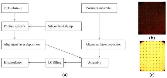
Figure 2.
Color online. (a) Flowchart of the manufacturing process of optically rewritable electronic paper; photomicrographs of (b) planar and (c) twisted NLC orientations. Cylindrical spacer diameter: ΔL = 20 µm; distance between spacers: L = 200 μm.
Microphotographs in Figure 2b,c show the top view of two LC alignment structures. It can be seen that the arrangement of spacers is fairly uniform. In practice, typical values of L can range within 60 and 200 μm and ΔL ranges between 5 and 25 μm. This means that the spacers cannot be directly detected by human eye.
Assume that the director alignment is parallel to the surface of the pillars in its vicinity. This condition can be achieved by photoalignment. The corresponding disorder of the director alignment undoubtedly must have the effect on macroscopic optical properties. In the next section we will study surface alignment of the director field with complex alignment structure providing the corresponding volumetric distortions.
3. Theoretical Model
Spacers with highly adhesive surface make the cell damage-free when it is deformed and provide better director alignment. In this section we aim to show that our experimental observations impose the constraint for the ratio = 10, which yields acceptable surface-induced director distortions, i.e., undetectable with the naked eye. Correspondingly, the coefficient of the surface coverage of the spacer s ≈ 0.785%.
3.1. Model of Surface-Induced Director Alignment
It seems an obvious step to consider the potential of uniformly ordered spacers by considering director alignment on photosensitive surface. Let the function φ(x, y) define director’s azimuthal angle on the photosensitive surface. According to the elasticity theory, free energy of NLC in the one-constant approximation has the form [15]:
Consequently, in-plane director field can be found if we assume that the z-component of vector n is 0 (see Figure 1b). This enables us to express the director as follows: , where is the azimuthal angle. Consequently, the Frank distortion energy (3) takes the form:
The task of finding director distribution in the plane of photosensitive substrate consists of minimization of the Frank free-energy functional (4) with the boundary conditions, provided by it. Following the variational principle, one can compose the Euler equation, which corresponds to the free energy minimum:
where and are the normalized coordinates. In the absence of spacers, it is convenient to assume perfect alignment of the director, i.e., φ = 0. However, the presence of spacers induces inhomogeneities in director alignment, which contribute to the formation of distortions in the bulk. A primary goal is to minimize the relative area of the inhomogeneities. This is achieved if the ratio , where r is the radius of the spacer and director is aligned along the tangential direction of the spacer surface. In practice, the ratio ranges within 15–20. Clearly, the assumption of circular uniformly spaced spacers reduces computational complexity. This provides the ability to calculate the derivative of the spacer surface for further using as the boundary conditions.
Following the proposed geometry (Figure 1a), let the director have tangential alignment on the surfaces of spacers. Then, one can consider a sufficiently large area with relatively small spacer of radius of 0.05 in the center (0.5; 0.5), which deforms the director field. Having defined the equation of the circle, we can calculate its derivative for the top and down arcs. Assuming that and , one can plot the solution of Equation (5). Without loss of generality, we assume that the azimuthal angle distribution is periodic along the (x; y) plane with the unit period. Then the resulting model distribution takes the form, which is depicted in Figure 3.
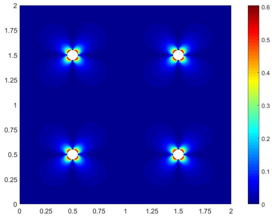
Figure 3.
Color online. Model distribution of director on photosensitive surface. Parameters: r = 0.05, L = 1. The color bar indicates the range of azimuthal angle.
Simulation of the director field shows insignificance of the area with highly disordered surface alignment. In particular, for our example, the ratio between the spacers cross-sectional area and the total area is about 0.785%. Bulk effects from the spacers must also be taken into account. Such a solution, however, is not necessary, especially after several the experiments. As we will see in the experimental Section 4, the inhomogeneities of the director field in the vicinity of the cylindrical spacers are not sensitive for human eye perception. This enables us to investigate optical properties of ORW e-paper under the assumption that the substrate is flat.
3.2. Simulation of Optical Performance
Simulation of optical characteristics can be carried out by using the 8 × 8 transfer matrix method. This approach employs theory of general methods of calculation of optical characteristics of anisotropic stratified media by Berreman and Yeh and the theory of partial coherence [16].
The idea of simulation of optical performance is that the voltage-off optical properties of any liquid crystal display are determined by its twist angle 0 ≤ ϕ ≤ 90° and retardation Δnd, where Δn is the birefringence of twisted nematic display. The retardation can also be represented by an angle dΔn/λ where λ is the wavelength of light. The concept of the interaction of quasimonochromatic light with the ORW e-paper is based on the spectral representation: the incident light is regarded as the composition of monochromatic components of different wavelengths, each of which interacts with the optical system independently of the others. Together with the input polarizer angle α = 0, and the output analyzer angle γ = π/2, all the important optical properties, such as the transmission and reflectance spectra, the contrast ratio, can be calculated. Since ORW e-paper is a reflective device, consider the reflectance coefficient:
The insight of the reflectance coefficient for the two states shows that the reflective state has a weak dependence of the wavelength, while the “dark state” does not manifest spectral dependence (see Figure 4a).
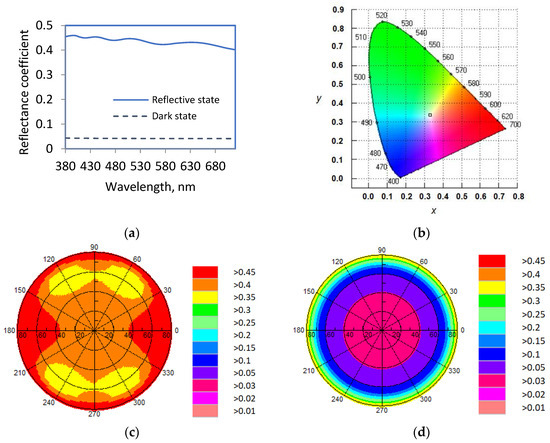
Figure 4.
Color online. (a) Reflectance spectra for reflective and dark states of the ORW e-paper; (b) simulated CIE 1931 chromaticity diagram. Hemispherical directional reflectance for the twist angle of (c) 90° and (d) 0°. Liquid crystal layer thickness: 13.64 μm.
Once the value Δnd is calculated for the liquid crystal layer, the change of color coordinates of the liquid crystal is due solely to the interference of polarized beams; for equal values of Δnd their transmission spectra must be the same. Thus, one can calculate Δnd for the sample of ORW e-paper. The simulated color triangle indicates identical color points in the CIE 1931 chromaticity coordinates (X, Y) for “reflective” and “dark” states of the ORW e-paper (Figure 4b). Here X and Y are normalized intensity values of red (R) and green (G), respectively. Although blue (B) does not have its own axis in the diagram, it is accounted for in the equations for X and Y:
This result was obtained by using MOUSE-LCD optimization software and it represents a practical, robust and generalized computational tool.
The investigation of viewing angle dependence was also carried out by exploiting the features of quasimonochromatic light propagation in layered systems. This method allows treatment with equal ease coherent and incoherent interactions between the fractions of light propagating in the layered system. We then calculate the viewing angle dependences for reflective and dark states of ORW e-paper. Solutions presented below were found by means of MOUSE-LCD as well (see Figure 4c,d). Parameters of the problem are summarized in Table 1. Spectral data for complex refractive index of aluminum were used for the metal reflector. Calculation of the reflectance coefficients shows that it is symmetric with respect to the angle of observation (see Figure 4c,d).

Table 1.
Material parameters describing the ORW e-paper.
We have also transformed the data in Figure 4a,b into the calculation of the contrast ratio. For the given structure, the contrast ratio achieves 13:1, which is highly desirable ORW e-paper device [17]. In spite of excellent reflectance coefficient and contrast ratio, there is a drawback in the choice of polarizers, which must have almost ideal transmittance spectra for all wavelengths of visible light.
In addition to the significance of light-reflective and color characteristics, the effect of variation in the incident angles on polarization characteristics has also been investigated. Polarization state of the incident light is characterized with the polarization degree, ellipticity and scatter of angular geometry. This arrangement enables to acquire all components of the Stokes vector S = (S0, S1, S2, S3), which describes all possible polarization states of light. This vector provides valuable information about reflecting characteristics and polarization degree: . Under the assumption that the incident light is taken to have a unit intensity, the corresponding Stokes parameters of the output light can be considered in some sense as characteristics of the modeled device. The ratio between the intensity of the component of the output light with the given polarization state to the intensity of the incident light can also be calculated, and we will define it as PSA TR (Polarizer–Sample–Analyzer Transmittance/Reflectance ratio) with the 84.11° orientation angle of the major axis (see Figure 5a). Following the mathematical relationships between the Stokes parameters, the ratio between the minor and major axes of the ellipse is −2 × 10⁻⁴ [18].
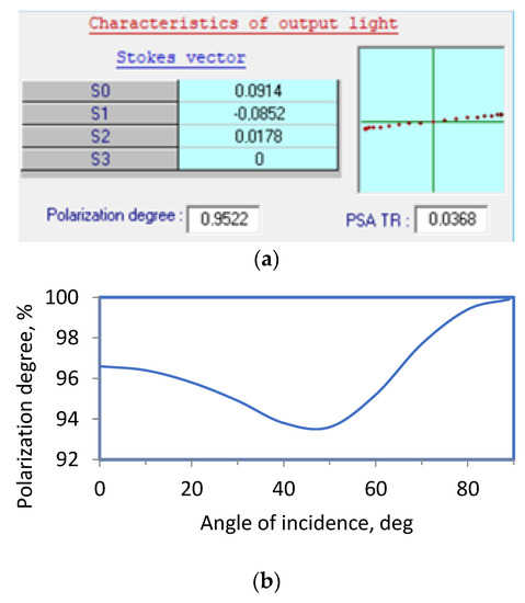
Figure 5.
(a) Typical MOUSE LCD window with the output light characteristics; (b) dependence of the polarization degree versus the angle of incidence.
Further insight into optical performance of ORW e-paper is gained when the polarization degree versus the angle of incidence is considered. The transmitted electric fields propagate through a certain thickness of polyimide and alignment layers. The polarization of the light changes as it propagates through these layers as coherent reflection occurs at the interfaces of alignment layers and polyimide. Consequently, the polarization degree is sensitive to the angle of incidence. The graph plotted in Figure 5b represents the dependence of the polarization degree versus the angle of incidence. As can be noticed in Figure 5b, the degree of polarization is relatively high with the minimum at 45°.
High polarization degree (⪅100%) is clearly important in ORW e-paper for maximizing the contrast ratio. It is also important that the indirect methodology employed in this section explains the calculated contrast ratio.
4. Results and Discussion
Following the flowchart depicted in Figure 2a, we applied the stamp printing method for fabrication of flexible ORW e-paper. Application of this technique provides regularly distributed spacers on the polyethersulfone substrate spin coated with SD1 layer. Photoinsensitive layer of compound HPL008 (Dainippon Ink and Chemicals, Japan) was also spin coated onto PES substrate backed with the polarizer. After providing the initial alignment direction of the first substrate and fixing the alignment direction of the second substrate, the two substrates were bonded together with epoxy resin. The obtained cell was filled in a vacuum with NLC. After exposing the cell with ultraviolet light, the desired image is obtained. Figure 6 represents the result of the experimental study exhibiting predominant short wavelengths of visible light (see also Figure 4a, where short wavelengths have reflectance coefficient). The image is clear and has a good quality, illustrating uniformity of the cell gap.
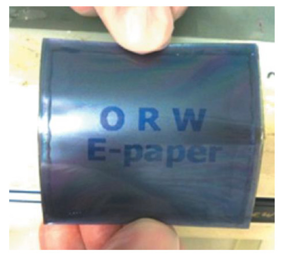
Figure 6.
Recorded sample image on flexible ORW e-paper.
According to the experimental findings, the ratio = 10 is optimal for flexible ORW e-paper. It also follows from Equation (2) that any increase of distance L results in a greater deformation of the top plate. Consequently, the LC layer thickness can be stabilized by the plate with a greater elasticity modulus, Ep. Therefore, designing of flexible ORW e-paper is a tradeoff between mechanical, geometrical and optical properties of the plates and spacers.
Considering the findings of our investigation, we conclude that uniform distribution of cylindrical spacers is the most suitable technique for fabrication of ORW e-paper and simulation of its optical performance. Experimental investigation has shown that there is no visible difference between flat and curved cells. This fact enabled us to calculate optical characteristics on flat substrates. The calculated reflectance coefficient (≈42%) and the contrast ratio of 13:1 superior other existing e-paper technologies. In view of the experimental results, we argue that this method is the most suitable for mass production.
5. Conclusions
In order to achieve acceptable optical characteristics for ORW e-paper, it is necessary to show that the role of the spacer-induced director inhomogeneities is insignificant. Correct selection of the ratio between the distance between spacers and cylindrical spacer diameter is the most significant factor affecting the image quality. For uniform distribution of cylindrical pillars, contrast ratio, mean reflectance coefficient and polarization state, have demonstrated to provide the most acceptable results. The finding on the simulated CIE 1931 chromaticity diagram indicates that by color theory guided application, neutral color characteristics can be established.
This work showed that for the development of flexible ORW e-paper technology for practical applications, both the uniform ordering of spacers and quasimonochromatic light propagation in layered systems must be considered.
Author Contributions
Writing—calculations, review and editing, A.K. and V.C. All authors have contributed substantially to the work reported. All authors have read and agreed to the published version of the manuscript.
Funding
This research was funded by the Russian Science Foundation, grant number 20-19-00201. The authors are grateful to Jiatong Sun (Donghua University, Shanghai, China) for providing the experimental data.
Institutional Review Board Statement
Not applicable.
Informed Consent Statement
Not applicable.
Data Availability Statement
Not applicable.
Conflicts of Interest
The authors declare no conflict of interest.
References
- Yang, Z.; Zhan, T.; Wu, S.T. Polarization-independent liquid crystal-based refractive index sensor. J. Soc. Inf. Disp. 2021, 29, 305–310. [Google Scholar] [CrossRef]
- Li, X.; Au, P.T.; Xu, P.; Muravsky, A.; Muravsky, A.; Liu, Z.; Chigrinov, V.; Kwok, H.S. P-153: Flexible Photoaligned Optically Rewritable LC display. In Proceedings of the SID Symposium Digest of Technical Papers, San Francisco, CA, USA, 4–6 June 2006; pp. 783–785. [Google Scholar]
- Park, S.; Wang, G.; Cho, B.; Kim, Y.; Song, S.; Ji, Y.; Yoon, M.-H.; Lee, T. Flexible molecular-scale electronic devices. Nat. Nanotechnol. 2012, 7, 438–442. [Google Scholar] [CrossRef] [PubMed]
- Sivaranjini, B.; Mangaiyarkarasi, R.; Ganesh, V.; Umadevi, S. Vertical alignment of liquid crystals over a functionalized flexible substrate. Sci. Rep. 2018, 8, 8891. [Google Scholar] [CrossRef] [PubMed]
- Lee, Y.; Kim, W.; Lee, J.H.; Kim, Y.M.; Yun, M.H. Understanding the Relationship between User’s Subjective Feeling and the Degree of Side Curvature in Smartphone. Appl. Sci. 2020, 10, 3320. [Google Scholar] [CrossRef]
- Sivaranjini, B.; Ganesh, V.; Umadevi, S. Bent-core liquid crystal-functionalised flexible polymer substrates for liquid crystal alignment. Liq. Cryst. 2020, 47, 838–850. [Google Scholar] [CrossRef]
- Kataoka, M.; Okada, H. In-plane switching liquid crystal cells using patterned printing electrodes and fine groove structures. Liq. Cryst. 2020, 47, 1735–1743. [Google Scholar] [CrossRef]
- Zhang, Y.; Sun, J.; Liu, Y.; Shang, J.; Liu, H.; Liu, H.; Gong, X.; Chigrinov, V.; Kwok, H.S. A flexible optically re-writable color liquid crystal display. Appl. Phys. Lett. 2018, 112, 131902. [Google Scholar] [CrossRef]
- Khandelwal, H.; van Heeswijk, E.P.; Schenning, A.P.; Debije, M.G. Paintable temperature-responsive cholesteric liquid crystal reflectors encapsulated on a single flexible polymer substrate. J. Mater. Chem. C 2019, 7, 7395–7398. [Google Scholar] [CrossRef]
- Ishinabe, T.; Fujikake, H. Optical design of flexible liquid crystal displays. In High Quality Liquid Crystal Displays and Smart Devices; Institution of Engineering and Technology: London, UK, 2019; pp. 207–222. [Google Scholar]
- Maruyama, N.; Kumashiro, Y.; Yamamoto, K. Development of cell gap spacer in LCD for ink-jet printing. In Proceedings of the 2008 2nd Electronics System-Integration Technology Conference, Institution of Engineering and Technology, Greenwich, UK, 1–4 September 2008; pp. 985–988. [Google Scholar]
- Chigrinov, V.G.; Kudreyko, A.A. Tunable optical properties for ORW e-paper. Liq. Cryst. 2021, 48, 1073–1077. [Google Scholar] [CrossRef]
- Kudreyko, A.; Chigrinov, V. Optimization of image writer modes for optically rewritable electronic paper. Liq. Cryst. 2022, 4, 436–441. [Google Scholar] [CrossRef]
- Lagerwall, S.T.; Muravski, A.A.; Yakovenko, S.Y.; Konovalov, V.A.; Minko, A.A.; Tsarev, V.P. Pressure-Insensitive Liquid Crystal Cell 2001. U.S. Patent No. 6,184,967, 6 February 2001. [Google Scholar]
- De Gennes, P.-G.; Prost, J. The Physics of Liquid Crystals; Oxford University Press: Oxford, UK, 1993; Volume 83. [Google Scholar]
- Yakovlev, D.A.; Chigrinov, V.G.; Kwok, H.-S. Modeling and Optimization of LCD Optical Performance; John Wiley & Sons: Hoboken, NJ, USA, 2015. [Google Scholar]
- Heikenfeld, J.; Drzaic, P.; Yeo, J.S.; Koch, T. A critical review of the present and future prospects for electronic paper. J. Soc. Inf. Disp. 2011, 19, 129–156. [Google Scholar] [CrossRef]
- Collett, E. Polarized light. Fundamentals and applications. In Optical Engineering; Dekker: New York, NY, USA, 1992. [Google Scholar]
Publisher’s Note: MDPI stays neutral with regard to jurisdictional claims in published maps and institutional affiliations. |
© 2022 by the authors. Licensee MDPI, Basel, Switzerland. This article is an open access article distributed under the terms and conditions of the Creative Commons Attribution (CC BY) license (https://creativecommons.org/licenses/by/4.0/).