Article

Strain-Induced Self-Rolling of Electrochemically Deposited Co(OH)2 Films into Organic–Inorganic Microscrolls

1
Physical Chemistry—Colloidal Systems, Department of Chemistry, University of Bayreuth, Universitaetsstrasse 30, 95447 Bayreuth, Germany
2
Physical Chemistry I, Department of Chemistry, University of Bayreuth, Universitaetsstrasse 30, 95447 Bayreuth, Germany
3
Bavarian Polymer Institute, University of Bayreuth, Universitaetsstrasse 30, 95447 Bayreuth, Germany
*
Author to whom correspondence should be addressed.
Crystals 2022, 12(8), 1072; https://doi.org/10.3390/cryst12081072
Submission received: 30 June 2022 / Revised: 25 July 2022 / Accepted: 27 July 2022 / Published: 31 July 2022
(This article belongs to the Special Issue Women in Mineralogical Crystallography and Biomineralization)

Abstract

:
Strain-induced self-folding is a ubiquitous phenomenon in biology, but is rarely seen in brittle geological or synthetic inorganic materials. We here apply this concept for the preparation of three-dimensional free-standing microscrolls of cobalt hydroxide. Electrodeposition in the presence of structure-directing water-soluble polyelectrolytes interfering with solid precipitation is used to generate thin polymer/inorganic hybrid films, which undergo self-rolling upon drying. Mechanistically, we propose that heterogeneities with respect to the nanostructural motifs along the surface normal direction lead to substantial internal strain. A non-uniform response to the release of water then results in a bending motion of the two-dimensional Co(OH)2 layer accompanied by dewetting from the substrate. Pseudomorphic conversion into Co3O4 affords the possibility to generate hierarchically structured solids with inherent catalytic activity. Hence, we present an electrochemically controllable precipitation system, in which the biological concepts of organic matrix-directed mineralization and strain-induced self-rolling are combined and translated into a functional material.

1. Introduction

In the light of a growing demand for clean energy conversion and storage systems, the role of hydrogen technology has become progressively more important. Consequently, substantial scientific and industrial research efforts have been dedicated to the development of hydrogen-based fuel cells and electrolysis equipment in the recent past. To ensure an adequate applicability, efficiency, and a broad availability of sustainable technological solutions, however, robust, active catalyst materials exhibiting structural stability over a large number of electrochemical cycles need to be established to reduce the overpotential, a figure of merit for efficient electrochemical water-splitting, as much as possible. These requirements are met, for instance, by some transition metal oxides including Co3O4 [1]. Besides the chemical composition of the catalyst, nanoscale structuring of the material can significantly affect the catalytic performance, e.g., due to the stabilization of stationary active centers and the creation of a high number of reaction sites [2,3].
Electrodeposition has established itself as one of the most effective methods for nano-structuring of inorganic materials. This technique stands out from other deposition methods due to its high deposition rates, low cost and effort, precisely controllable experimental parameters, and remarkable product purity [4]. As another advantage, precipitation occurs directly on the conductive substrate, such that the deposited structures themselves form the electrode surface. Hence, further use as an active electrode material, e.g., in water-splitting applications, does not require additional preparation steps. Moreover, structure-directing additives can be used conveniently and their influence on the formation and transformation of catalyst structures can be easily analyzed.
A well-described property of thin films and coating is their instability towards dewetting, as exemplarily reported by Reiter for polystyrene films on silicon when annealed above the glass transition temperature [5]. Dewetting of as-deposited thin films occurs spontaneously as a result of surface energy minimization, thus generating a large driving force for agglomeration of thin layers into particles with dimensions on the micron and nanometer scale [6]. In view of technological applications relying on robust homogenous coatings, dewetting is usually considered as unfavorable and needs to be inhibited [6]. Recent examples for a targeted prevention of dewetting include the stabilization of silver thin films by implantation of silicon and indium atoms [7] and the stabilization of polymer bilayers by adding gold nanoparticles to the top layer [8]. In some cases, however, thin film dewetting processes are intentionally induced to achieve the formation of desired structures, as reported, for instance, by Bonvicini et al. for metallic and bimetallic nanostructures [9]. In our here-presented work, thin film dewetting is actively used as a strategy for the formation of self-supported hierarchical organic–inorganic microscrolls with coiled morphologies.
When considering synthetic strategies for the preparation of inorganic materials with complex hierarchical structures, nature can serve as a rich source of inspiration, as biogenic minerals, such as bones, teeth, or mollusk shells characteristically demonstrate elaborate structural organization down to the nanometer scale. An important principle of bio-mineralization is the induction and regulation of mineral deposition by soluble and insoluble organic matrices [10]. A well-known example is that of vertebrate bones, whose astounding mechanical properties originate from the combination of organic molecules (collagen) and inorganic minerals (hydroxyapatite) [11]. Similar organic/inorganic nanocomposite structures are also observed in sea urchin spines, mussel shells, and corals [12,13,14,15,16,17]. Even though the content of occluded organics is usually very minor in these systems, they exert strong effects on the architecture and properties of the material [18]. The elaborate hierarchical structures of biominerals, which exhibit remarkable adaptation to specific functions, while being formed under ambient conditions, have sparked imagination in view of artificial materials with complex architecture. A particularly facile concept inspired from biological mineralization is the use of water-soluble polyelectrolyte additives, mimicking highly acidic proteins associated with mollusk shells, to direct the crystallization of synthetic materials. An intriguing example is the formation of calcite mesocrystals mediated by the negatively charged polymer poly(4-styrene sulfonate) (PSS) [19], where the additive drives the precipitation of the solid along a non-classical particle-based mechanism relying on the aggregation of initially stabilized primary units (amorphous or crystalline) [20,21]. As the influence of organic additives can lead to complex crystalline nanostructures with well-ordered superordinate arrangements [22], a substantial number of studies have been devoted towards the translation of bioinspired crystallization concepts into functional inorganic materials [23,24], including Co3O4 [25,26].
In a recent study on polymer-mediated precipitation of Co(OH)2, an important precursor to cobalt(II,III) oxide, Gruen et al. used polyethyleneimine (PEI) as an organic structure-directing polyelectrolyte to achieve the deposition of a mineral film at the air/solution interface. Intriguingly, upon drying, the resulting two-dimensional sheets of amorphous cobalt hydroxide occluding a very minor content of organics underwent strain-induced self-rolling into free-standing spirals with up to six twists, which were subsequently pseudomorphically converted into crystalline Co3O4 coils with mesoscale channels [27]. As the self-rolling phenomenon of the largely inorganic mineral films critically relied on the presence of PEI, the polymer additive was discussed to facilitate slight differences in the deposition regimes between the air- and the solution-exposed side of the film, such that non-uniform structural motifs with a different capacity for water absorption emerged along the surface normal direction.
In general, self-folding of two-dimensional materials is based on compositional or structural heterogeneities (e.g., density, morphology) [28] along the cross-section. While strain-induced self-rolling of heterogeneous two-dimensional bilayer, multilayer, or gradient systems is a common phenomenon in nature, especially in the plant kingdom [29,30], and has been translated into artificial soft matter systems [31,32], this concept is scarcely reported for geological and synthetic minerals due to the high bending strain which needs to be accommodated by these brittle materials to introduce curvature.
Remarkable examples for self-rolling in inorganic precipitation systems include manganese oxide microtubules, prepared by Tolstoy et al., where the density of sheet packing decreases within the film [33]. Lepidocrocite (γ-FeOOH) microtubes which are formed by drying-induced self-rolling due to a moisture gradient along the cross-section were reported by Strykanova et al. In a next step, the authors were able to coat the inner surface of the lepidocrocite microtubes with silver nanoparticles to form an inorganic composite [34]. Hybrid inorganic–organic microscrolls were also produced by Takahashi et al., who used differences in hydrophilicity as a driving force for the self-rolling process. Again, a modification of hybrid films with nanoparticles was successfully achieved, which also allows the controlled release of entrapped particles [35].
On an even smaller length scale, bilayer structures originating from heterogeneities in lattice constants within a thin inorganic film can equally build up strain, which is eventually released by self-rolling into nanotubes, as reported by Schmidt et al. [36]. From these examples it becomes evident that the experimental conditions allowing for the deposition of non-uniform inorganic films range from gas–solution interfacially directed techniques [27,28,33,34] over spin-coating [35] to selective etching techniques [36].
In this work, we explore the fabrication of three-dimensional self-supported cobalt hydroxide microscrolls based on the strain-induced self-rolling of electrochemically deposited thin films with heterogenous nanostructure.

2. Materials and Methods

2.1. Chemicals and Materials

Cobalt nitrate hexahydrate (Co(NO3)2·6H2O) and potassium sulfate (K2SO4) was purchased in analytical grade from Merck KGaA (Darmstadt, Germany). Poly(sodium 4-styrene sulfonate) (PSS, average Mw 75,000 g mol−1), poly(allylamine hydrochloride) (PAH, average Mw 17,500 g mol−1), and potassium chloride (KCl, 3 mol L−1, BioUltra) were obtained from Sigma-Aldrich Chemie GmbH (Steinheim, Germany). Sodium hydroxide solutions (NaOH, 0.1 mol L−1 and 1 mol L−1 in water) were purchased from Grüssing GmbH (Filsum, Germany). Hellmanex III solution was purchased from Hellma GmbH & Co. KG (Müllheim, Germany). All chemicals were applied directly as received from the suppliers without further purification, and aqueous solutions were prepared with deionized water (resistivity 18.2 MΩ cm, Milli-Q Advantage A10, Merck KGaA, Darmstadt, Germany).
Glass slides coated with a conductive layer of fluorine-doped tin oxide (FTO, item number TEC 8A, glass thickness: 2.2 mm, resistance: 8 Ω/sq) were purchased from XOP Glass (XOP Física SL, Castellón, Spain) and cleaned according to the following procedure: The substrates were cleaned in a ultrasonic bath for 10 min, sequentially with the use of an aqueous Hellmanex III solution (5 wt%), acetone, ethanol, and aqueous NaOH solution (1 mol L−1). After each step, the substrates were rinsed with the corresponding solvent and air-dried at room temperature.

2.2. Electrochemical Deposition and Characterization of Cobalt Hydroxide Thin Films and Their Conversion into Cobalt (II,III) Oxide

All electrochemical depositions and electrochemical measurements were performed within a three-electrode electrochemical cell with a PGSTAT204 potentiostat (Metrohm Autolab B.V., Utrecht, The Netherlands). The setup comprised a silver/silver chloride reference electrode (Ag|AgCl, item number 6.0726.100, Metrohm, inner filling: potassium chloride (KCl, 3 mol L−1), outer filling: potassium sulfate (K2SO4, 0.1 mol L−1)) and a platinum counter electrode (Pt, item number 3.109.0790, Metrohm).
Deposition of Co(OH)2. Thin films of cobalt hydroxide were produced by cathodic electrochemical deposition (CED) on FTO-coated glass slides connected as working electrode (Figure 1). The exposed areas of both the working electrode and counter electrode were 1 cm2 and the distance between both electrodes was adjusted to 2 cm. All three electrodes were centrally positioned in the reaction container and immersed in an aqueous cobalt nitrate solution ([Co(NO3)2·6H2O] = 50 mmol L−1), both under polymer-free conditions and in the presence of PSS or PAH as structure-directing additives ([polymer] = 4.2 mg mL−1). To induce galvanostatic Co(OH)2 deposition, a constant current of −0.5 mA was applied to the FTO substrate for 30 min.
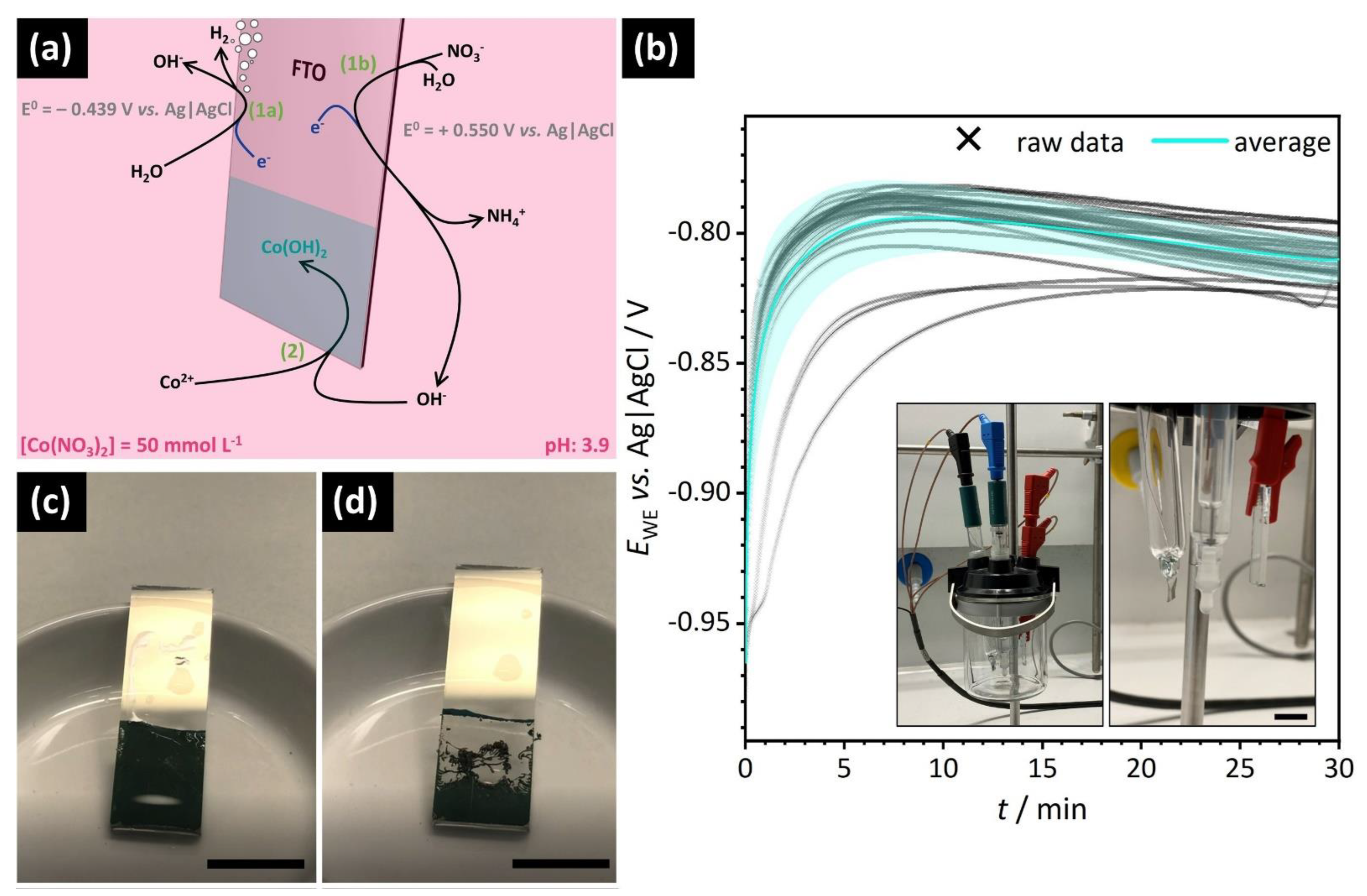
As illustrated in Figure 1a, the principle of the CED is based on the formation of hydroxide anions near the working electrode according to Equations (1a) and (1b) followed by basic precipitation of solid Co(OH)2 in the presence of Co2+ directly on the FTO surface (Equation (2)).
2   H 2 O + 2   e     2   OH +   H 2
NO 3 + 7   H 2 O + 8   e     NH 4 + + 10   OH
Co 2 + + 2   OH     Co ( OH ) 2
The reaction potentials provided in Figure 1a are derived from the literature and were recalculated to account for the pH value of the Co(NO3)2 electrolyte solution (pH = 3.9 at start of the electrodeposition) [37]. Detailed calculations are presented in the Supporting Information. Figure 1b shows the potential profiles for a series of CED experiments performed under the same conditions and their average curve. The electrochemical system stabilizes after a few minutes, such that a relatively constant potential is measured during electrodeposition using the setup shown as inset. The deposited films initially appear smooth and a homogeneous green coating of the entire immersed electrode surface is observed directly after the CED (Figure 1c). During the first minutes of drying, however, the polymer-mediated solid Co(OH)2 layers undergo complete dewetting from the substrate accompanied by conspicuous self-rolling into spiraling morphologies (Figure 1d). For further investigation, the dewetted films were left to dry in air at room temperature.
Pseudomorphic Conversion into Co3O4. To achieve transformation of the hydroxide precursor into catalytically active Co3O4, selected samples were subjected to a thermal treatment performed under air atmosphere in a Carbolite Gero ELF 1100 oven (Carbolite Gero GmbH & Co. KG, Neuhausen, Germany). The temperature was gradually increased with a heating rate of 5 K min−1 and the target temperature of 300 °C was held for 2 h.
Oxygen evolution electrocatalysis. The catalytic properties of non-scrolled Co(OH)2 films were tested by electrochemical water-splitting experiments using the anodic oxygen evolution as a model reaction. An aqueous solution of sodium hydroxide (0.1 mol L−1) was used as electrolyte/reagent. Linear potential sweeps were performed in the window between 0.0 V and 2.0 V vs. Ag|AgCl with a scan rate of 10 mV s−1. The measured potential Emeas was corrected with respect to the cell resistance and the current i (Equation (3a)). Additionally, the cell potential was converted to the potential vs. the reversible hydrogen electrode (RHE) using a standard potential E Ag | AgCl 0 of 0.205 V and a pH value of 13. (Equation (3b)). The potential at a threshold current density of 10 mA cm−2 was then used to determine the overpotential η (Equation (3c)).
E corr = E meas i R
E RHE = E meas + E Ag | AgCl 0 + 0.059 · p H
η = E 10   mA   cm 2 E O 2 | H 2 O 0

2.3. Structural and Compositional Characterization of the Products

The structure and composition of electrochemically deposited cobalt hydroxide precipitates prepared in the absence and presence of structure-directing polymer additives were analyzed using a wide range of imaging, scattering, and spectroscopy methods.
General morphologies and detailed structures of the samples were imaged by digital light microscopy (DLM) using a VHX-950F with a VH-Z250R lens system from Keyence Deutschland GmbH (Neu-Isenburg, Germany) and by scanning electron microscopy (SEM) using a Zeiss LEO 1530 VP Gemini from Carl Zeiss AG (Oberkochen, Germany) operated at an acceleration voltage of 3 kV. In preparation for SEM measurements, film fragments were mounted on a standard sample holder by conductive adhesion graphite-pads and sputtered with a conductive layer of platinum (layer thickness: 1.3 nm) using a Cressington Sputter Coater 208 HR from Cressington Scientific Instruments UK (Watford, United Kingdom). Cross-sectional views were achieved by manual positioning of individual spirals. To investigate the elemental composition of polymer/mineral spirals, energy-dispersive X-ray spectroscopy (EDX) maps were recorded by an UltraDry SDD detector from Thermo Fischer Scientific (Waltham, MA, United States of America) at an acceleration voltage of 20 kV.
Confocal Raman microscopy was performed with a WITec alpha 300 RA+ instrument from WITec GmbH (Oxford Instruments, Abingdon, United Kingdom). For the spatially resolved acquisition of Raman spectra, the excitation lasers with wavelengths of 532 nm and 785 nm, respectively, were operated at 1 mW.
Dynamic light scattering (DLS) on PSS solutions ([PSS] = 4.2 g L−1) subjected to different Co2+ ion concentrations ([Co2+] = 0 mmol L−1, 50 mmol L−1), was performed with a Zetasizer Nano-ZS ZEN3600 (wavelength λ = 638 nm) from Malvern Panalytical (Malvern, United Kingdom) in automatic mode at 25 °C. Samples were measured in disposable PMMA cuvettes purchased by Brand GmbH (Wertheim, Germany). Data acquisition and processing were conducted with the Zetasizer Software (version: 7.13) provided by the supplier.
For small-angle X-ray scattering (SAXS) measurements, which were performed using a Double Ganesha AIR system from SAXSLAB/Xenocs, deposited microscrolls were scratched off the FTO substrates, crushed with a mortar, and filled in glass capillaries (Ø = 1 mm, Hilgenberg, Malsfeld, Germany). Monochromatic radiation (λ = 1.54 Å) was provided by a rotating anode (generator: Micro 7 HFM with rotating copper anode) from Rigaku Corporation (Tokyo, Japan). Two-dimensional scattering patterns were collected with a position-sensitive PILATUS 300 K detector from Dectris (Philadelphia, PA, USA) which was placed at different distances from the sample. The radially averaged profiles of the scattering intensity I(q) versus the modulus of the scattering vector q were corrected for background, an assumed sample thickness of 1 mm, accumulation time as well as absorption, and subsequently merged.
The electrodeposited precipitates before and after calcination were investigated by powder X-ray diffraction (PXRD) performed with a STOE STADI P Mythen2 4K diffractometer (Stoe & Cie. GmbH, Darmstadt, Germany) equipped with a Ge (111) monochromator and four Dectris MYTHEN2 R 1K detectors in Debye–Scherrer geometry. Diffractograms were recorded in an angular range of 2θ = 2°–140° at room temperature using Ag–Kα radiation (λ = 0.56 Å). Prior to the measurements, all samples were sealed in glass capillaries (Ø = 1 mm, Hilgenberg, Malsfeld, Germany).

3. Results

Thin films of Co(OH)2 were prepared by cathodic electrochemical deposition (CED) on FTO substrates in the absence and presence of sulfonate- or amine-functionalized polymer additives.

3.1. Electrochemical Deposition and Self-Rolling of Co(OH)2 Films in the Presence of Poly(styrene sulfonate)

Inspired by the multiple actions of biomineralization-associated water-soluble proteins and their mimesis in the form of synthetic polyelectrolytes in bio-inspired crystallization systems, we here explore the possibility to use poly(styrene sulfonate) (PSS) as a structure-directing additive in the electrochemically controlled precipitation of cobalt hydroxide. A continuous coating of the substrate is routinely achieved both under additive-free conditions and in the presence of PSS. Upon removal from the electrolyte solution, pure Co(OH)2 films remain flat and attached to the FTO surface, while undergoing a minor degree of microcrack formation during drying. Intriguingly however, the polymer-mediated films fracture into mm-sized pieces, which are prone to substantial self-rolling, such that microscrolls with multiple twists can be obtained (Figure 2). Digital light microscopy (DLM) images (cf. Figure 2a) display curled fragments of the deposited mineral film, where the characteristic green color indicates the formation of alpha cobalt hydroxide according to the previously discussed electrochemical formulas.
Due to the relatively well-reproducible deposition conditions across the exposed electrode surface, the deposited films can be assumed to be laterally homogenous, which results in the absence of imprinted directionality for self-rolling. In combination with the irregular fragmentation of the film during dewetting (cf. Figure S1), a broad size distribution and variable shapes of microscrolls are obtained. The fragments are completely detached from the FTO surface and can easily be transferred for further investigation. A more detailed view of an individual microscroll highlights that curling in some cases even originates from two different directions (Figure 2b). Examination in different in-plane positions along the respective film cross-section allows to estimate a mean thickness of 6.59 ± 0.27 µm. While the curling motion does not follow a specific pattern and the number of twists varies between microscrolls (Figure 2a), the general phenomenon of self-rolling is highly reproducible and the radius of curvature is relatively constant between 10 µm and 30 µm.
Visible bending and curling of the deposited solid-state film already start a few minutes after removal from the reactant solution. Interestingly, variations of the drying process showed that substrates can be stored while immersed in water and still undergo self-rolling when exposed to air after several days of storage. Additionally, it is possible to store substrate-attached mineral films in ice at freezing temperatures without any noticeable effect on the self-rolling behavior. The speed of drying can also be increased by placing the substrates on a heating plate at T = 100 °C, which leads to a stronger fragmentation of the polymer-mediated Co(OH)2 film, resulting in smaller pieces, which, however, still show a substantial tendency towards curling.

3.2. Morphology and Nanostructure of the Microscrolls

More detailed analysis of microscrolls with various sizes and number of twists was performed by scanning electron microscopy (SEM) imaging (Figure 3 and Figure S2), revealing that the surface of each microscroll is structured on the nanoscale. The cross-section of selected microscrolls is presented in images with higher magnification (Figure S2 and Figure 3a). As a common feature, the polymer-mediated Co(OH)2 films displayed a structurally heterogeneous bilayer arrangement observable as a bifurcated cross-section (Figure 3b). Specifically, the film exhibits a less-ordered nanostructure towards the outside of the microscroll (referred to as convex surface) and a more ordered pillar-like nanostructure towards the inside of the microscroll (referred to as concave surface). These bifurcated structural features are highly reproducible across all investigated spirals and are consistent with the concept of disordered film growth directly at the FTO surface in the initial stages of the CED process, while a more well-defined growth follows later on, presumably under the stabilizing of the added polyelectrolyte. This hypothesis is supported by the conspicuous absence of more ordered growth regime when using a pure cobalt nitrate solution without any additive (Figure S3).
Small-angle X-ray scattering (SAXS), as a quantitative, volume-sensitive method, shows similar results (Figure S4). The porous structure of the more ordered part of the bilayer, which is seen in SEM images (cf. Figure 3b), correlates to an intensity decay scaling with a power law of ca. I~q−3. Small granular units are obtained during sample preparation such that the pores are oriented in all spatial directions. Hence, these structural motifs give rise to a 2D isotropic SAXS pattern. The intensity decay proportional to q−3 is characteristic for disordered pore systems and can be explained accordingly. Differences observed between the scattering patterns of additive-free Co(OH)2 films and Co(OH)2/PSS microscrolls in the q-range below 0.5 nm−1 allow for the suggestion that the nanostructural motifs are modulated by the presence of PSS. Thus, the SAXS measurements complement the findings from the SEM imaging. Moreover, the suppression of self-rolling in non-bifurcated polymer-free Co(OH)2 films strongly emphasizes the critical role of the polyelectrolyte in generating non-uniform structural motifs along the surface normal direction as a prerequisite for strain-induced self-rolling.

3.3. Composition of the Microscrolls

To analyze the distribution of the polyelectrolyte throughout the cross-section of the microscrolls, energy-dispersive X-ray spectroscopy (EDX) was performed on selected samples (Figure 4).
A representative film cross-section is depicted in Figure 4a, and characteristic X-ray radiation signals specific for cobalt (Co, Figure 4b), oxygen (O, Figure 4c), and sulfur (S, Figure 4d) are mapped. The relative signal intensities indicate Co and O as the main elements forming the microscrolls and their distribution appears homogeneous throughout the entire analyzed surface. These results are consistent with Co(OH)2 as the expected major constituent of the structure and are supported by powder X-ray diffraction (PXRD) measurements (Figure S5), even though a partial oxidation of cobalt hydroxide to spinel-type cobalt oxide (Co3O4) cannot be ruled out. Reflections at 2θ = 3.3°, 4.9°, 6.7°, and 8.2°, respectively (+ in Figure S5), are attributed to the 00l series of Co(OH)2 with an interlayer spacing of d003 = 9.8 Å. This value is slightly higher than expected from the literature, and thus may result from the intercalation of PSS [38]. In combination with the characteristic green color of the film, these results indicate α-Co(OH)2 to be deposited. Differences from the expected intensity decay along the 00l series can be explained by an overlap of various reflections at 2θ = 6.7°. For the as-deposited Co(OH)2 film, most of the reflections can be assigned to Co(OH)2 (ref. PDF 96-154-8811), while a partial oxidation at air leads to the presence of Co3O4 reflections (x in Figure S5, ref. PDF 96-153-8532). The incorporation of PSS (>in Figure S5) into the material is evidenced by a reflection at 2θ = 14.8° [39]. The XRD data of thermally treated microscrolls do not show any reflections for the 00l series, and the vast majority of signals are attributable to spinel-type Co3O4. Few reflections are assigned to CoO as a byproduct (<in Figure S5, ref. PDF 96-153-3088). XRD data therefore confirm the successful thermal conversion of the α-Co(OH)2/PSS hybrid material into Co3O4 microscrolls.
The occlusion of PSS into the film is further evidenced by the detection of pronounced sulfur signals in EDX (Figure 4d). Moreover, the homogenous distribution of polymer suggests that there is no significant compositional heterogeneity within the composite material. The fine dispersion of PSS throughout the structure further indicates the formation of an organic–inorganic hybrid material composed of cobalt hydroxide and PSS in the polyelectrolyte-mediated CED process
Further investigation of the PSS distribution across the surface normal direction of the films was performed by confocal Raman microscopy. (Figure 5). Based on an examination of the Raman spectrum of the hybrid spirals (Figure S6), vibration bands detected at wavenumbers of 507 cm−1 (corresponding to Co–O vibrations) and 1600 cm−1 (corresponding to aromatic vibrations of PSS), respectively, were identified as representative signals associated with the inorganic and the polymer phase, respectively. The intensities of these bands were then recorded in line scans from the concave to the convex surface at different spots along the cross-section (Figure 5a). The step size for mapping was set to 100 nm. As a result, almost identical intensity distribution profiles were obtained for both Co–O and aromatic vibrations (Figure 5b). Therefore, Raman microscopy provided no indication of a heterogenous distribution or gradient in relative polymer content, thus confirming the results from EDX analysis. However, an overall intensity gradient along the scanning direction is visible for both signals, indicating general density differences along the crossection. Accordingly, the disordered material near the convex surface of the microscroll appears to be less dense than the more ordered pillar-like structures on the concave side. These results are confirmed by a line scan in a different lateral position (Figure S7).

3.4. Electrochemical Characterization of Additive-Free Co(OH)2 Films and Their Calcination Products

In a next step, linear potential sweeps (LPS) were recorded to further investigate redox behavior as well as the electrocatalytic performance of electrodeposited Co(OH)2. For an initial assessment, polymer-free samples were investigated as these films do not readily detach from the substrate and can be directly applied as the working electrode in an electrochemical experiment. Self-rolled Co(OH)2/PSS microscrolls, in turn, may open exciting future prospects for the development of compact self-supported electrode materials with coiled morphology and mesoscale channels originating from loose curling [27]. However, their integration into an electrochemical cell requires adaption and optimization of the standard measurement setup.
In view of potential applications in heterogeneous catalysis, selected Co(OH)2 film samples were calcined at 400 °C to induce transformation into Co3O4. Successful transformation into spinel-type cobalt(II,III) oxide is confirmed by PXRD (Figure S5). Most importantly, pseudomorphic conversion preserving the micron-scale morphology was observed, while porosity is generated by the elimination of water during the decomposition of the hydroxide precursor [40].
In order to investigate the electroactive species in both the as-deposited cobalt hydroxide films and their calcination products, LPS profiles were recorded (Figure S8). While a broad signal covering the potential range of 200 mV–400 mV vs. Ag|AgCl indicates multiple oxidation events attributable to the transition of CoII to CoIII in the as-deposited film, the LPS profile of the thermally treated sample is largely dominated by a signal related to the formation of the catalytically active CoIV species from CoIII (570 mV vs. Ag|AgCl) in agreement with an expected composition of CoIICoIII2O4 [41].
We then increased the potential window to induce the anodic oxygen evolution reaction (OER) according to the equation 4 OH → O2 +2H2O + 4e and compared the capacity of as-deposited and calcined mineral films to act as efficient electrocatalysts for this reaction. The OER as a model reaction represents a critical process currently limiting the implementation of clean energy conversion systems based on water-splitting due to the involved complex four-electron transfer, which typically leads to significant overpotentials. In the assessment of electrocatalytic activity, the overpotential represents the excess potential as compared to the theoretical standard potential of the reaction (E0H2O/O2 = 1.229 V vs. the reversible hydrogen electrode, RHE), which needs to be applied to reach a certain current density (here: 10 mA cm−2) [42]. Our experiments yielded similar overpotentials of ηi = 10 mA cm−2 = 416 mV for the Co(OH)2 and ηi = 10 mA cm−2 = 412 mV for the Co3O4 films, respectively. These values are in the range of, and even slightly lower than, the parameters of nanostructured Co3O4 materials obtained by calcination of cobalt hydroxide carbonate precursors with urchin-like (ηi = 10 mA cm−2 = 461 mV) [26] and spherulitic (ηi = 10 mA cm−2 = 463 mV) [40] morphologies. The latter were measured on a rotating disc electrode, providing improved transport characteristics compared to the static electrode investigated here. This highlights the enormous potential of electrodeposition processes in directing the formation of functional inorganic meso- and nanostructures.

4. Discussion

Our results revealed intriguing self-supported microscroll morphologies formed upon drying of electrodeposited cobalt hydroxide films. The formation of these structures critically requires the presence of a structure-directing polyelectrolyte. In this, we would like to highlight that the self-rolling phenomenon mediated by the sulfonate-functionalized negatively charged polymer PSS could be reproduced with amine-functionalized poly(allylamine hydrochloride) (PAH), as summarized in Figure S9 in the Supporting Information. This important observation suggests that the mechanism for self-rolling does not rely solely on the exact chemical nature of the polymer additive (in particular, its net charge), but rather on its ability to interact with Co2+ ions or early-stage species of mineralization in solution and near the electrode surface to interfere with the precipitation and crystallization process. Therefore, we suspect that a general polymer—metal—interaction promotes the additive-mediated electrodeposition of mineral films with heterogeneous nanostructure. Such interplays are well-documented in solution-based Ca2+/polyelectrolyte systems, where crystallization into calcium carbonate can proceed via colloidal clusters formed from an initially deposited amorphous precursor phase. The polyelectrolyte stabilizes this precursor phase and can eventually be found occluded in the final crystallized product [16]. Such non-classical crystallization mechanisms have also been observed in a variety of precipitation systems and are not unique to calcium carbonate [20].
The presence of Co(II)/polymer complexes in solution prior to electrodeposition can be regarded as an important indicator for a polymer-mediated non-classical crystallization process. These aggregates represent the primary species interacting with the electrode surface, where precipitation is induced by reaction with hydroxide ions. In support of such a hypothesis, dynamic light scattering (DLS) analysis, indeed, shows such complexes (Figure S10). While an aqueous solution of PSS already contains aggregates with a size of 27 nm (presumably stabilized by Na+ ions) even in the absence of Co(II), the signal becomes narrower and more intense when Co2+ ions are added, thus indicating well-defined metal-bridged polymer aggregates.
When considering potential mechanisms for self-rolling of the deposited hybrid films, passive self-folding phenomena in two-dimensional biological or polymeric soft matter systems are usually achieved by a bilayer, multilayer, or gradient structure, in which different layers show a distinct response to an external stimulus. In inorganic films, non-uniform properties along the surface normal direction can be implemented via heterogeneities in growth regimes/nanostructure [27], composition/hydrophilicity [35], or lattice constants [36]. Internal strain then leads to different displacements between the layers, resulting in deformation and bending of the structure.
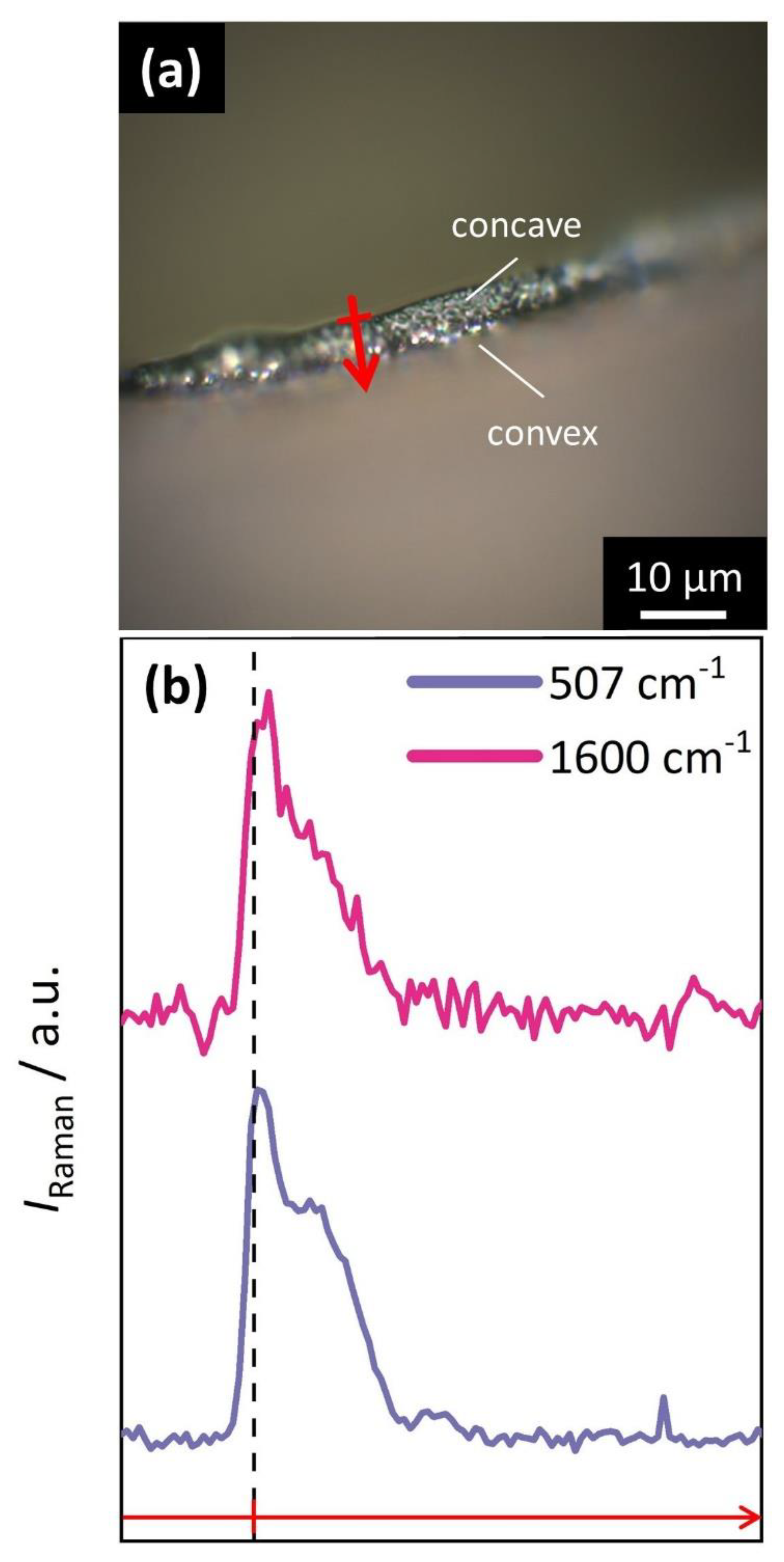
In the here-presented precipitation system, the separation of the deposited polymer–inorganic hybrid films into two domains, comprising a disordered and less-dense nanostructure at the convex surface and a more ordered one at the concave surface, integrates well with the discussed concepts of self-rolling. Specifically, we propose that the differently structured layers exhibit different capacities for the absorption of intrastructural water, thus undergoing a non-uniform degree of volume-shrinkage during drying, resulting in the build-up of internal strain as a driving force for self-rolling. The deposited films show a strong anisotropy along the surface normal direction with regard to their drying behavior, an observation which is comparable to other self-rolling materials. In general, heterogeneities in the structure give rise to a non-uniform mechanical response of the material to external stimuli, such as electrical signals [43], temperature changes [44], the exposure to water in combination with swelling phenomena [35], or, as presented in this work, the release of intrastructural water during drying. The internal stress that builds up within the material due to the anisotropic response to external conditions is ultimately released by a bending motion, which can create complex three-dimensional structures.
An important question in this context is the origin of the bilayer structure. Considering the formation of the film via CED, it is important to note that immediately after applying a potential to the working electrode, a first layer of Co(OH)2 nucleates directly on the FTO surface. Afterwards, deposition takes place at the newly formed Co(OH)2 surface.
As observed through SEM imaging (Figure 3 and Figure 6a), the first formed Co(OH)2 layer appears less ordered than the subsequently formed material. This structural distinction could be explained by a stronger structure-directing effect of the polyelectrolyte in the later stages of the electrodeposition. However, this potential effect is not reflected in the composition of the film, as both EDX and Raman microscopy point to a homogenous distribution of polymer throughout the hybrid material. Hence, PSS is uniformly incorporated during the entire deposition procedure.
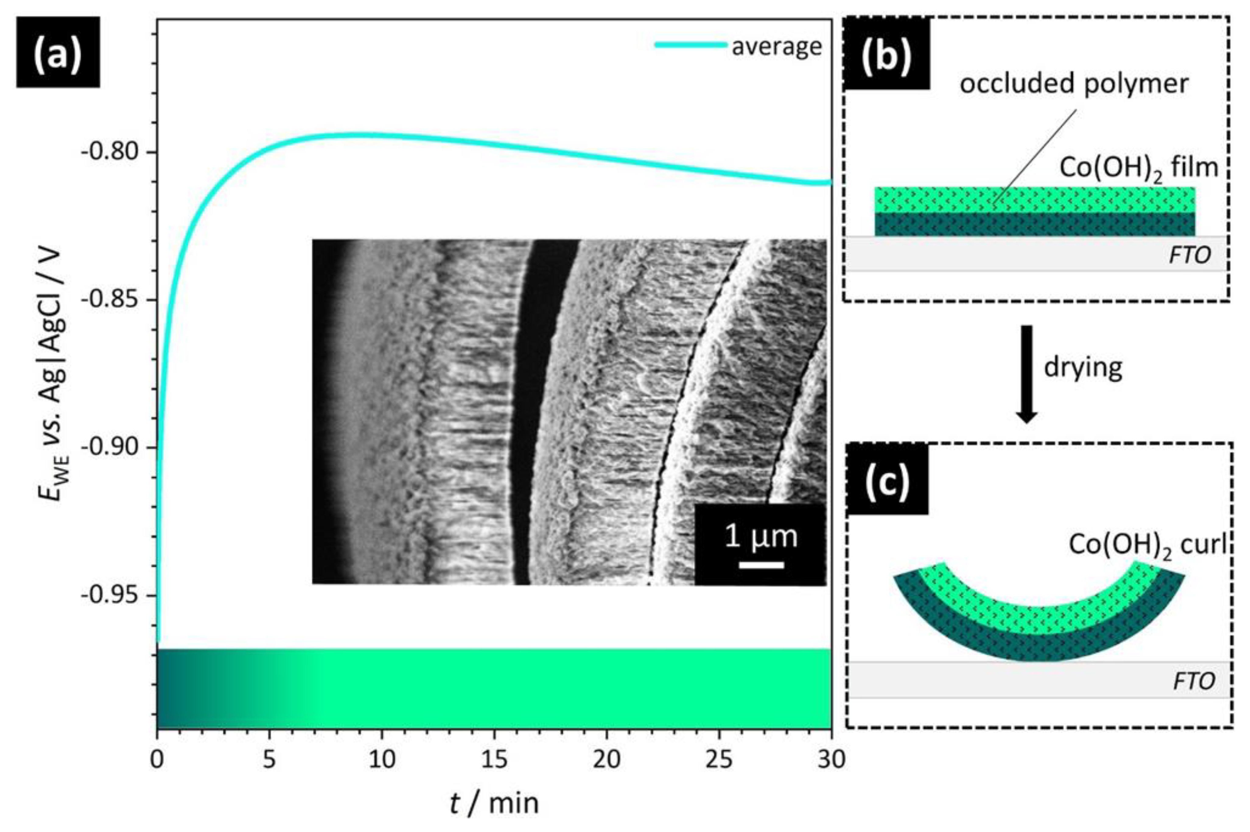
The deposition potential EWE, in contrast, varies during the process and only stabilizes a few minutes into the electrodeposition (Figure 6a). Here lies a possible cause for the bilayer formation. In particular, the less-ordered layer at the convex surface of the hybrid films is structurally similar to the cross-sections of Co(OH)2 films deposited in the absence of polyelectrolytes (Figure S3). Hence, the most dominant factor leading to the rapid formation of disordered material may be the strong tendency for precipitation due to the initially more negative electrode potential and the lower resistance at the FTO surface compared to the subsequently formed Co(OH)2 surface. In other words, a first layer of highly disordered Co(OH)2 is formed, because the driving force for uncontrolled rapid precipitation exceeds the stabilization effect of the organic additive. This layer is nucleated to the FTO substrate and upon dewetting becomes the convex surface of the microscroll (Figure 6a, inset). The higher precipitation rate, however, does not affect the concentration of polymer occluded within the material. The subsequently deposited more-well-defined layer of Co(OH)2 is in contact with the reactant solution during the CED process and eventually becomes the concave surface of the coiled film fragments. Here, the impact of the polyelectrolyte is enhanced due to the more positive potential and the lower driving force of un-regulated precipitation, resulting in generally slower reaction kinetics and a higher level of structural organization.
As schematically illustrated in Figure 6b,c, our proposed mechanism proceeds via the deposition of a polymer/Co(OH)2 hybrid film on FTO (Figure 6b). Upon drying, internal strain builds up due to differences in drying speed and volume shrinkage between both layers. As a result, a microscroll is formed (Figure 6c). Finely dispersed organic additives are occluded in both parts of the bilayer, which is in conformity with the results of EDX analysis.

5. Conclusions

In summary, we successfully applied the bioinspired concept of polymer-mediated crystallization for the electrodeposition of hierarchically structured cobalt hydroxide films. Non-uniform nanostructural organization separates the PSS/Co(OH)2 films into two domains with different capacity for binding intrastructural water. Consequently, pronounced strain-induced self-rolling into spiral patterns is observed upon drying accompanied by dewetting from the substrate, such that self-supported three-dimensional microscrolls are obtained. Our results highlight the importance of the polymer additive and we discuss its role at different stages of the electrodeposition. Therefore, this work contributes to the understanding of self-folding mechanisms in inorganic matter and, at the same time, provides an example for the intentional use of dewetting phenomena for the preparation of functional materials with complex structure.
In order to gain further insights into the self-rolling mechanism of inorganic–organic hybrid films, our future studies concentrate on the influence of geometrical parameters, such as thickness and lateral dimensions of the film fragments, on their strain-induced self-folding into microscrolls. In view of potential applications as a free-standing electrode for water-splitting electrocatalysis, coiled structures with mesoscale channels may enable efficient transport of gaseous products while simultaneously offering a compact arrangement with increased stiffness as compared to flat films [45]. Perspectively, this facile concept based on highly reproducible deposition conditions under electrochemical control may also be transferable into a wider range of material systems with diverse intrinsic and curvature-dependent [46] functional properties.

Supplementary Materials

The following supporting information can be downloaded at: https://www.mdpi.com/article/10.3390/cryst12081072/s1, Calculations of the potentials for the hydroxide-generating electrochemical reactions; Figure S1: Digital light microscopy imaging of Co(OH)2/poly(styrene sulfonate) (PSS) microscrolls; Figure S2: Scanning electron micrographs of individual Co(OH)2/PSS microscrolls; Figure S3: Comparison of film cross-sections in the absence and presence of PSS; Figure S4: Small-angle X-ray scattering patterns for non-scrolled Co(OH)2 films and Co(OH)2/PSS microscrolls; Figure S5: X-ray diffractograms of Co(OH)2 microscrolls prior to and after thermal treatment; Figure S6: Representative Raman spectrum of a selected Co(OH)2 microscroll; Figure S7: Confocal Raman microscopy line scan along the cross-section of an individual Co(OH)2/PSS microscroll; Figure S8: Comparison of OER performance of additive-free Co(OH)2 films as deposited and after pseudomorphic conversion to Co3O4 films; Figure S9: Overview of the deposition of Co(OH)2/poly(allylamine hydrochloride) hybrid materials; Figure S10: Dynamic light scattering data of aqueous PSS solutions with increasing additions of Co2+ ions.

Author Contributions

Conceptualization, J.S. and A.S.S.; methodology, J.S. and A.S.S.; investigation, J.S. and S.R.; formal analysis, J.S., S.R. and A.S.S.; data curation, J.S. and S.R.; writing—original draft preparation, J.S.; writing—review and editing, S.R. and A.S.S.; visualization, J.S. and S.R.; supervision, A.S.S.; project administration, A.S.S.; funding acquisition, J.S. and A.S.S. All authors have read and agreed to the published version of the manuscript.

Funding

This research was funded by the University of Bayreuth. Further support was received by the Bavarian Academy of Sciences and Humanities (Young Academy) via an individual fellowship to A.S.S.

Institutional Review Board Statement

Not applicable.

Informed Consent Statement

Not applicable.

Data Availability Statement

Not applicable.

Acknowledgments

We thank the Bavarian Polymer Institute (BPI) for providing access to electron microscopy and X-ray scattering facilities within the KeyLabs “Electron and Optical Microscopy” and “Mesoscale Characterization: Scattering Techniques”, respectively. J.S. thanks the Elite Study Program Macromolecular Science within the Elite Network of Bavaria for support. The authors are grateful to Christine Kellner for SEM image acquisition, Florian Puchtler for XRD data acquisition, and Holger Schmalz for support with Raman microscopy measurements.

Conflicts of Interest

The authors declare no conflict of interest.

References

  1. Menezes, P.W.; Indra, A.; Zaharieva, I.; Walter, C.; Loos, S.; Hoffmann, S.; Schlögl, R.; Dau, H.; Driess, M. Helical Cobalt Borophosphates to Master Durable Overall Water-Splitting. Energy Environ. Sci. 2019, 12, 988–999. [Google Scholar] [CrossRef] [Green Version]
  2. Li, X.; Hao, X.; Abudula, A.; Guan, G. Nanostructured Catalysts for Electrochemical Water Splitting: Current State and Prospects. J. Mater. Chem. A 2016, 4, 11973–12000. [Google Scholar] [CrossRef]
  3. Schlögl, R. Heterogene Katalysatoren–Fundamental Betrachtet. Angew. Chem. 2015, 127, 3531–3589. [Google Scholar] [CrossRef] [Green Version]
  4. Gurrappa, I.; Binder, L. Electrodeposition of Nanostructured Coatings and Their Characterization—A Review. Sci. Technol. Adv. Mater. 2008, 9, 043001. [Google Scholar] [CrossRef]
  5. Reiter, G. Dewetting of Thin Polymer Films. Phys. Rev. Lett. 1992, 68, 75–78. [Google Scholar] [CrossRef]
  6. Thompson, C.V. Solid-State Dewetting of Thin Films. Annu. Rev. Mater. Res. 2012, 42, 399–434. [Google Scholar] [CrossRef]
  7. Chi, L.; Bassim, N. Ag Thin Film Dewetting Prevention by Ion Implantation. Adv. Mater. Interfaces 2019, 6, 1900108. [Google Scholar] [CrossRef]
  8. Das, A.; Dey, A.B.; Manna, G.; Sanyal, M.K.; Mukherjee, R. Nanoparticle-Mediated Stabilization of a Thin Polymer Bilayer. Macromolecules 2022, 55, 1657–1668. [Google Scholar] [CrossRef]
  9. Bonvicini, S.N.; Fu, B.; Fulton, A.J.; Jia, Z.; Shi, Y. Formation of Au, Pt, and Bimetallic Au-Pt Nanostructures from Thermal Dewetting of Single-Layer or Bilayer Thin Films. Nanotechnology 2022, 33, 235604. [Google Scholar] [CrossRef]
  10. Boskey, A.L. Biomineralization: An Overview. Connect. Tissue Res. 2003, 44, 5–9. [Google Scholar] [CrossRef]
  11. Fratzl, P.; Weinkamer, R. Nature’s Hierarchical Materials. Prog. Mater. Sci. 2007, 52, 1263–1334. [Google Scholar] [CrossRef] [Green Version]
  12. Vecchio, K.S.; Zhang, X.; Massie, J.B.; Wang, M.; Kim, C.W. Conversion of Sea Urchin Spines to Mg-Substituted Tricalcium Phosphate for Bone Implants. Acta Biomater. 2007, 3, 785–793. [Google Scholar] [CrossRef]
  13. Suzuki, M.; Nagasawa, H. Mollusk Shell Structures and Their Formation Mechanism. Can. J. Zool. 2013, 91, 349–366. [Google Scholar] [CrossRef]
  14. Drake, J.L.; Mass, T.; Stolarski, J.; Von Euw, S.; van de Schootbrugge, B.; Falkowski, P.G. How Corals Made Rocks through the Ages. Glob. Chang. Biol. 2020, 26, 31–53. [Google Scholar] [CrossRef] [PubMed] [Green Version]
  15. Schenk, A.S.; Zlotnikov, I.; Pokroy, B.; Gierlinger, N.; Masic, A.; Zaslansky, P.; Fitch, A.N.; Paris, O.; Metzger, T.H.; Cölfen, H.; et al. Hierarchical Calcite Crystals with Occlusions of a Simple Polyelectrolyte Mimic Complex Biomineral Structures. Adv. Funct. Mater. 2012, 22, 4668–4676. [Google Scholar] [CrossRef] [Green Version]
  16. Xu, Y.; Tijssen, K.C.H.; Bomans, P.H.H.; Akiva, A.; Friedrich, H.; Kentgens, A.P.M.; Sommerdijk, N.A.J.M. Microscopic Structure of the Polymer-Induced Liquid Precursor for Calcium Carbonate. Nat. Commun. 2018, 9, 2582. [Google Scholar] [CrossRef] [PubMed] [Green Version]
  17. Bergström, L.; Sturm née Rosseeva, E.V.; Salazar-Alvarez, G.; Cölfen, H. Mesocrystals in Biominerals and Colloidal Arrays. Acc. Chem. Res. 2015, 48, 1391–1402. [Google Scholar] [CrossRef] [PubMed]
  18. Seto, J.; Ma, Y.; Davis, S.A.; Meldrum, F.; Gourrier, A.; Kim, Y.Y.; Schilde, U.; Sztucki, M.; Burghammer, M.; Maltsev, S.; et al. Structure-Property Relationships of a Biological Mesocrystal in the Adult Sea Urchin Spine. Proc. Natl. Acad. Sci. USA 2012, 109, 3699–3704. [Google Scholar] [CrossRef] [Green Version]
  19. Wang, T.; Cölfen, H.; Antonietti, M. Nonclassical Crystallization: Mesocrystals and Morphology Change of CaCO3 Crystals in the Presence of a Polyelectrolyte Additive. J. Am. Chem. Soc. 2005, 127, 3246–3247. [Google Scholar] [CrossRef] [Green Version]
  20. Gebauer, D.; Cölfen, H. Prenucleation Clusters and Non-Classical Nucleation. Nano Today 2011, 6, 564–584. [Google Scholar] [CrossRef] [Green Version]
  21. Kim, Y.Y.; Schenk, A.S.; Ihli, J.; Kulak, A.N.; Hetherington, N.B.J.; Tang, C.C.; Schmahl, W.W.; Griesshaber, E.; Hyett, G.; Meldrum, F.C. A Critical Analysis of Calcium Carbonate Mesocrystals. Nat. Commun. 2014, 5, 4341. [Google Scholar] [CrossRef] [PubMed] [Green Version]
  22. Cölfen, H.; Mann, S. Higher-Order Organization by Mesoscale Self-Assembly and Transformation of Hybrid Nanostructures. Angew. Chem. Int. Ed. 2003, 42, 2350–2365. [Google Scholar] [CrossRef] [Green Version]
  23. Asenath-Smith, E.; Noble, J.M.; Hovden, R.; Uhl, A.M.; DiCorato, A.; Kim, Y.Y.; Kulak, A.N.; Meldrum, F.C.; Kourkoutis, L.F.; Estroff, L.A. Physical Confinement Promoting Formation of Cu2O-Au Heterostructures with Au Nanoparticles Entrapped within Crystalline Cu2O Nanorods. Chem. Mater. 2017, 29, 555–563. [Google Scholar] [CrossRef] [Green Version]
  24. Brunner, J.J.; Krumova, M.; Cölfen, H.; Sturm, E.V. Magnetic Field-Assisted Assembly of Iron Oxide Mesocrystals: A Matter of Nanoparticle Shape and Magnetic Anisotropy. Beilstein J. Nanotechnol. 2019, 10, 894–900. [Google Scholar] [CrossRef] [PubMed] [Green Version]
  25. Schenk, A.S.; Eiben, S.; Goll, M.; Reith, L.; John, E.; Kulak, A.N.; Meldrum, F.C.; Wege, C.; Ludwigs, S. Learning from Sea Shells–Bio-Inspired Approaches toward Mesoscale Architectures in Functional Spinel Oxides. Acta Crystallogr. Sect. A Found. Adv. 2016, 72, 55–56. [Google Scholar] [CrossRef] [Green Version]
  26. Schenk, A.S.; Eiben, S.; Goll, M.; Reith, L.; Kulak, A.N.; Meldrum, F.C.; Jeske, H.; Wege, C.; Ludwigs, S. Virus-Directed Formation of Electrocatalytically Active Nanoparticle-Based Co3O4 Tubes. Nanoscale 2017, 9, 6334–6345. [Google Scholar] [CrossRef]
  27. Gruen, V.; Helfricht, N.; Rosenfeldt, S.; Schenk, A.S. Interface-Mediated Formation of Basic Cobalt Carbonate/Polyethyleneimine Composite Microscrolls by Strain-Induced Self-Rolling. Chem. Commun. 2021, 57, 7244–7247. [Google Scholar] [CrossRef]
  28. Gulina, L.B.; Tolstoy, V.P.; Solovev, A.A.; Gurenko, V.E.; Huang, G.; Mei, Y. Gas-Solution Interface Technique as a Simple Method to Produce Inorganic Microtubes with Scroll Morphology. Prog. Nat. Sci. Mater. Int. 2020, 30, 279–288. [Google Scholar] [CrossRef]
  29. Wang, H.; Nilsen, E.T.; Upmanyu, M. Mechanical Basis for Thermonastic Movements of Cold-Hardy Rhododendron Leaves. J. R. Soc. Interface 2020, 17, 20190751. [Google Scholar] [CrossRef] [Green Version]
  30. Vogel, S.; Müller-Doblies, U. Desert Geophytes under Dew and Fog: The “Curly-Whirlies” of Namaqualand (South Africa). Flora-Morphol. Distrib. Funct. Ecol. Plants 2011, 206, 3–31. [Google Scholar] [CrossRef]
  31. Liu, L.; Jiang, S.; Sun, Y.; Agarwal, S. Giving Direction to Motion and Surface with Ultra-Fast Speed Using Oriented Hydrogel Fibers. Adv. Funct. Mater. 2016, 26, 1021–1027. [Google Scholar] [CrossRef] [Green Version]
  32. Liu, L.; Ghaemi, A.; Gekle, S.; Agarwal, S. One-Component Dual Actuation: Poly(NIPAM) Can Actuate to STable 3D Forms with Reversible Size Change. Adv. Mater. 2016, 28, 9792–9796. [Google Scholar] [CrossRef] [PubMed]
  33. Tolstoy, V.P.; Gulina, L.B. Synthesis of Birnessite Structure Layers at the Solution-Air Interface and the Formation of Microtubules from Them. Langmuir 2014, 30, 8366–8372. [Google Scholar] [CrossRef]
  34. Strykanova, V.V.; Gulina, L.B.; Tolstoy, V.P.; Tolstobrov, E.V.; Danilov, D.V.; Skvortsova, I. Synthesis of the FeOOH Microtubes with Inner Surface Modified by Ag Nanoparticles. ACS Omega 2020, 5, 15728–15733. [Google Scholar] [CrossRef] [PubMed]
  35. Takahashi, M.; Figus, C.; Malfatti, L.; Tokuda, Y.; Yamamoto, K.; Yoko, T.; Kitanaga, T.; Tokudome, Y.; Innocenzi, P. Strain-Driven Self-Rolling of Hybrid Organic-Inorganic Microrolls: Interfaces with Self-Assembled Particles. NPG Asia Mater. 2012, 4, e22. [Google Scholar] [CrossRef] [Green Version]
  36. Schmidt, O.G.; Eberl, K. Thin Solid Films Roll up into Nanotubes. Nature 2001, 410, 168. [Google Scholar] [CrossRef]
  37. Therese, G.H.A.; Kamath, P.V. Electrochemical Synthesis of Metal Oxides and Hydroxides. Chem. Mater. 2000, 12, 1195–1204. [Google Scholar] [CrossRef]
  38. Ma, R.; Liu, Z.; Takada, K.; Fukuda, K.; Ebina, Y.; Bando, Y.; Sasaki, T. Tetrahedral Co(II) Coordination in α-Type Cobalt Hydroxide: Rietveld Refinement and X-Ray Absorption Spectroscopy. Inorg. Chem. 2006, 45, 3964–3969. [Google Scholar] [CrossRef]
  39. Kim, J.; Park, C.; Im, S.; Lee, H.; Kim, J.H. Effect of Molecular Weight Distribution of PSSA on Electrical Conductivity of PEDOT:PSS. RSC Adv. 2019, 9, 4028–4034. [Google Scholar] [CrossRef] [Green Version]
  40. Schenk, A.S.; Goll, M.; Reith, L.; Roussel, M.; Blaschkowski, B.; Rosenfeldt, S.; Yin, X.; Schmahl, W.W.; Ludwigs, S. Hierarchically Structured Spherulitic Cobalt Hydroxide Carbonate as a Precursor to Ordered Nanostructures of Electrocatalytically Active Co3O4. Cryst. Growth Des. 2020, 20, 6407–6420. [Google Scholar] [CrossRef]
  41. Casella, I.G.; Gatta, M. Study of the Electrochemical Deposition and Properties of Cobalt Oxide Species in Citrate Alkaline Solutions. J. Electroanal. Chem. 2002, 534, 31–38. [Google Scholar] [CrossRef]
  42. McCrory, C.C.L.; Jung, S.; Peters, J.C.; Jaramillo, T.F. Benchmarking Heterogeneous Electrocatalysts for the Oxygen Evolution Reaction. J. Am. Chem. Soc. 2013, 135, 16977–16987. [Google Scholar] [CrossRef] [PubMed]
  43. Jiang, H.; Fan, L.; Yan, S.; Li, F.; Li, H.; Tang, J. Tough and Electro-Responsive Hydrogel Actuators with Bidirectional Bending Behavior. Nanoscale 2019, 11, 2231–2237. [Google Scholar] [CrossRef]
  44. Ionov, L.; Stoychev, G.; Jehnichen, D.; Sommer, J.U. Reversibly Actuating Solid Janus Polymeric Fibers. ACS Appl. Mater. Interfaces 2017, 9, 4873–4881. [Google Scholar] [CrossRef]
  45. Karnaushenko, D.; Kang, T.; Schmidt, O.G. Shapeable Material Technologies for 3D Self-Assembly of Mesoscale Electronics. Adv. Mater. Technol. 2019, 4, 1800692. [Google Scholar] [CrossRef]
  46. Fernandez-Martinez, A.; Tao, J.; Wallace, A.F.; Bourg, I.C.; Johnson, M.R.; De Yoreo, J.J.; Sposito, G.; Cuello, G.J.; Charlet, L. Curvature-Induced Hydrophobicity at Imogolite-Water Interfaces. Environ. Sci. Nano 2020, 7, 2759–2772. [Google Scholar] [CrossRef]
Figure 1. Experimental approach for thin film deposition. (a) Schematic illustration of the FTO working electrode and overview of the electrochemical reactions leading to the formation of cobalt hydroxide (NHE: normal hydrogen electrode). (b) Potential profile of the conducted CED experiments as a function of deposition time (black: raw data; blue: average potential with error band). Inset: photograph of the experimental setup with a close-up of the three electrodes; the electrolyte was omitted for better visibility (scale bar: 1 cm). (c,d): Photographs of the cobalt hydroxide film on FTO (c) immediately after extraction from the aqueous environment and (d) during drying-induced dewetting and curling (scale bars: 1 cm).
Crystals 12 01072 g001
Figure 2. Digital light microscopy (DLM) images of Co(OH)2/PSS microscrolls. (a) Overview of curled fragments of the solid mineral film. Due to the lateral homogeneity of the film and the irregular fragmentation, the direction and exact pattern of self-rolling is unspecific. (b) Cross-section of an individual microscroll formed from a film fragment with an estimated mean thickness of 6.59 ± 0.27 µm.
Crystals 12 01072 g002
Figure 3. Scanning electron micrograph (SEM) images of Co(OH)2/PSS microscrolls. (a) Homogenously rolled microscroll with five twists and exposed cross-section. (b) Magnified view of the cross-section revealing a nanogranular substructure and a bifurcated arrangement separating the individual layers of the spiral into two distinct domains comprising less-ordered nanostructural motifs near the convex surface of the film and well-ordered pillar-like features near the concave surface.
Crystals 12 01072 g003
Figure 4. Energy-dispersive X-ray spectroscopy (EDX) mapping of the cross-section of an individual microscroll. (a) Corresponding SEM image of the analyzed microscroll. (bd) Elemental distribution of (b) cobalt, (c) oxygen, and (d) sulfur. Homogenous distribution patterns are observed for both cobalt and oxygen, representing the major elements of the mineral structure, as well as sulfur, indicating a uniform incorporation of PSS as a minority component throughout the film.
Crystals 12 01072 g004
Figure 5. Confocal Raman microscopy line scan along the cross-section of an individual microscroll. (a) Optical microscopy view of the corresponding film cross-section. The red arrow marks the selected position and the direction of scanning. (b) Distribution profile of Raman intensity along the scanning direction plotted for signals corresponding to the mineral (507 cm−1, Co–O vibrations; purple) and the polymer phase (1600 cm−1, aromatic vibrations; pink). The dashed vertical line indicates the position of the concave surface of the microscroll with respect to the scanning direction. An overall intensity gradient of identical profile shape is visible for both signals, which suggests density differences between the concave and convex surface.
Crystals 12 01072 g005
Figure 6. Proposed mechanism of hybrid organic–inorganic microscrolls. (a) Potential profile during CED experiments as a function of deposition time. The initially more negative potential early in the CED process results in a higher driving force for precipitation, leading to the formation of a poorly ordered Co(OH)2 layer (dark green) directly in contact with the substrate surface. Subsequently, a layer comprising well-ordered structural features (light green) is nucleated, presumably due to the gradually increasing structure-directing effect of the polyelectrolyte at increasingly less negative deposition potentials. The color bar at the bottom represents the formation of structurally distinct layers. Inset: SEM of a microscroll cross-section featuring several turns of the spiral structure. While the convex surface of the film was in contact with the electrode prior to dewetting, the concave side was exposed to the solution. (b) Schematic illustration of a flat Co(OH)2 film attached to the FTO substrate prior to the drying and dewetting process. A structurally non-uniform bilayer arrangement with occluded polymer in both layers is depicted. (c) Schematic illustration of a bent film as a result of a different response of structurally distinct sublayers to the release of intrastructural water.
Crystals 12 01072 g006
Publisher’s Note: MDPI stays neutral with regard to jurisdictional claims in published maps and institutional affiliations.

