Article

Effect of Design Parameters on the Flexural Strength of Reinforced Concrete Sandwich Beams

by
Vijayaprabha Chakrawarthi
1,
Leon Raj Jesuarulraj
2,
Siva Avudaiappan
3,4,*,
Divya Rajendren
2,
Mugahed Amran
5,6,*,
Pablo Guindos
4,
Krishanu Roy
7,
Roman Fediuk
8,9 and
Nikolai Ivanovich Vatin
9
1
Department of Civil Engineering, A.C. College of Engineering and Technology, Karaikudi 630001, India
2
Applied Civil Engineering Group, CSIR-North East Institute of Science and Technology, Jorhat Assam 785006, India
3
Departamento de Ingeniería Civil, Universidad de Concepción, Concepción 4030000, Chile
4
Centro Nacional de Excelencia para la Industria de la Madera (CENAMAD), Pontificia Universidad Católica de Chile, Av. Vicuña Mackenna 4860, Santiago 8330024, Chile
5
Department of Civil Engineering, College of Engineering, Prince Sattam Bin Abdulaziz University, Alkharj 16273, Saudi Arabia
6
Department of Civil Engineering, Faculty of Engineering and IT, Amran University, Amran 9677, Yemen
7
School of Engineering, The University of Waikato, Hamilton 3216, New Zealand
8
Polytechnic Institute, Far Eastern Federal University, 690922 Vladivostok, Russia
9
Peter the Great St. Petersburg Polytechnic University, 195251 St. Petersburg, Russia
*
Authors to whom correspondence should be addressed.
Crystals 2022, 12(8), 1021; https://doi.org/10.3390/cryst12081021
Submission received: 27 May 2022 / Revised: 19 July 2022 / Accepted: 20 July 2022 / Published: 22 July 2022

Abstract

:
Sandwich beams are preferable for aerostructure and marine structures due to their high mechanical strength, durability, stiffness, and fatigue resistance. This paper presents a study on the flexural behavior of sandwich beams made of self-compacting concrete comprising a polystyrene inner core with wire mesh reinforcement. The effect of the design parameters such as the inner core area, percentage of tension reinforcement, and wire mesh on the moment carrying capacity and failure modes of sandwich beams was analyzed. Ten beams were cast and tested to failure with simply supported end conditions and they were classified into three different groups. The longitudinal section of the inner core area was varied by 0% (control beam), 25%, 50%, and 75% of the gross area. The tension reinforcement ratio varied between 0.6 and 1.5%. In addition, the effect of the wire mesh in shear and flexural resistance was studied. The load-carrying capacity of sandwich beams increased with flexural reinforcement. In addition, the welded wire mesh improved the sandwich beams’ flexural and shear performance. The conventional expressions for the moment of resistance were valid for sandwich beams, whereas the shear strength expressions overestimated the capacity; therefore, modifications were suggested. The refined models had a significant agreement with the experimental results.

1. Introduction

The construction industry is always looking for new, better, and efficient systems [1,2]. At present, most of the problems faced by the construction industry are mainly due to the shortage of raw materials [3,4,5]. Hence, it is necessary to find out all possible ways to reduce the usage of concrete in structural members [6]. The sandwich structure is the structural element that consists of a multi-layer core of different materials [5,7]. It has an outer facing element and inner core element placed between the outer facing [8,9]. The outer facing takes up the bending, the inner core takes up the axial load, and the shear force is taken up by the bonding agent [10,11,12]. Sandwich structures were utilized in aerospace applications in the early 1960s and further found applicability in marine, civil, automotive, and high-performance structures [8,13,14]. The sandwich construction method has all desirable characteristics such as a high mechanical strength-to-weight ratio, economy, durability, and thermal and acoustic insulation, for all the main structural elements such as slabs, beams, transfer girders, columns, frames, walls, and stairs [15,16,17,18]. Sandwich panels made up of fiber-reinforced polymer, carbon-fiber-reinforced polymers were used in the last five decades [19,20,21].
A precast concrete sandwich panel (PCSP) consists of two internal and external pieces of concrete separated by insulation material such as polystyrene. These types of panels function in commercial buildings, residential buildings, and warehouses [9]. The amount of skin reinforcement and shear connectors governs the flexural behavior of ferrocement sandwich panels [22]. The outer parts and inner core are able to withstand different loading conditions such as tension, compression, and shear [23]. The bonding between the outer layer and inner core is very much essential to take up the stresses [24]. Debonding leads to a reduced load-carrying capacity due to the inefficient transfer of tensile and shear stresses. Moreover, the debonding due to compression tries to buckle the outer part from the inner core and progresses the separation to obtain potential collapse [25]. These types of defects in the sandwich structure reduce the efficiency of the structure to take up the forces such as cyclic, fatigue, and dynamic forces [26]. The structural behavior of sandwich panels under axial compression, eccentric, and flexural loading was investigated in the past [27,28,29,30]. In the dynamic test of a single-story sandwich building [31], discontinuous walls in-between the door and window openings are vulnerable to flexural cracking. The in-plane shear test results of a composite sandwich beam showed that the shear capacity and modulus of the skin govern the ultimate load [32]. Previous studies have shown that the flexural and shear behavior of different types of precast sandwich panels such as 3D panels [33,34,35], textile-reinforced-concrete-faced panels [36], glass-fiber-reinforced concrete beams/panels [36,37,38,39,40,41,42], and ferrocement panels performed better than the conventional members [43,44,45,46,47]. However, [48] the failure modes and failure mechanism of cast in situ-type, short and slender sandwich beams have not yet been reported in the literature.
Materials used in the fabrication of cast in situ-type sandwich members are structural concrete, polystyrene, steel reinforcement, and welded-wire mesh. Flowable or self-compacting concrete is usually adopted for wythes of sandwich members because of the small thickness and reinforcement congestion. The ultimate strength of self-compacting concrete (SCC) beams was similar to normal concrete beams [49,50,51]. Moreover, many designers use a minimum quantity of welded wire mesh in addition to the reinforcement bars in architectural and structural applications to ensure that the sandwich panels perform properly against flexure and shear stresses under service loads [2].
Sandwich beams are classified into three types, namely, noncomposite, composite, and partially composite [1,2]. The top and bottom wythes of fully composite and noncomposite members act as a single unit and independent, respectively. The bending stiffness and mechanical strength of partially composite members fall between fully composite and noncomposite members. In reality, sandwich beams are neither fully composite nor noncomposite. In sandwich flexural members, the top and bottom wythes resist flexural stresses and the side wythes resist both horizontal and vertical shear stresses [49,52]. However, there is the possibility to promote the composite action by increasing the tension reinforcement and by adding welded wire mesh, which were experimentally attempted in this study. As the degree of composite action is generally not known exactly, the verification of conventional shear and flexural strength expressions for sandwich beams is not possible without experimental results. The applicability of flexural strength expressions was validated, and a necessary modification was proposed for shear strength expression. Not much information is available on the structural behavior of RC sandwich beams especially regarding the stiffness, flexure, and shear strength. However, the aims of this study are (1) to arrive at an optimum geometry and reinforcement ratio; (2) to investigate the influence of wire mesh, wherein the beams provide a high bending strength and stiffness with low density; (3) to compare the experimental results with the shear strength and moment of resistance expressions suggested by the current design codes such as Indian, American, and European codes; (4) to obtain a modified model to evaluate the shear capacity based on the comparison of results; (5) to enable the design engineers to evaluate the shear capacity of such sandwich beams.

2. Experimental Procedure

2.1. Materials and Methods

The self-compacting concrete (SCC) was adopted for the outer core to ensure flow in between the congested reinforcement confinement. OPC 43 grade cement of specific gravity 3.12 was used according to IS 8112: 2013 [53]. Crushed angular granite metal of 10 mm in size from a local source was used as coarse aggregate with a specific gravity of 2.68. River sand belongs to the Zone III gradation as per IS 383 (2016) [54] with a specific gravity of 2.61 and was used in this experimental study. For trial purposes, three water-to-cement ratios (0.33, 0.42, and 0.46) and two types of super plasticizers, namely, Conplast and Cerahyperplast, were used to prepare the SCC mixes. The mix ratio of cement, sand, and coarse aggregate in concrete was kept constant as 1:1.5:1.37, whereas the water-to-cement ratio was varied in order to achieve the flow as well as the mechanical strength for two types of superplasticizers. Based on the flowability and compressive strength of SCC mixes, the water-to-cement ratio and type of plasticizer were adopted. Further, the yield strength ( f y ) and ultimate strength of tension and web reinforcement were 530–615 MPa and 495–580 MPa, respectively. The V-funnel test was used to check filling ability, whereas the J-ring, L-box, and U-box test were used to verify its passing ability. The slump flow test was used to measure the workability as a slump value. The observed results were checked with limiting values of EFNARC guidelines. The compressive strength of SCC was carried out in a compression testing machine of 2000 kN capacity. Cube specimens of size 150 mm × 150 mm × 150 mm were cast to test the compressive strength of concrete.

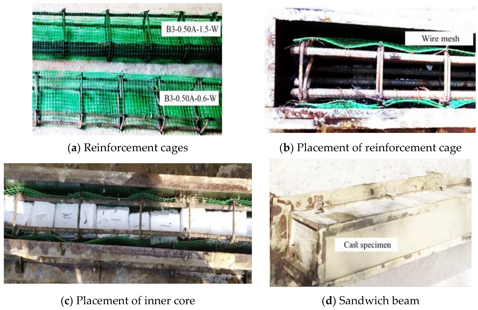
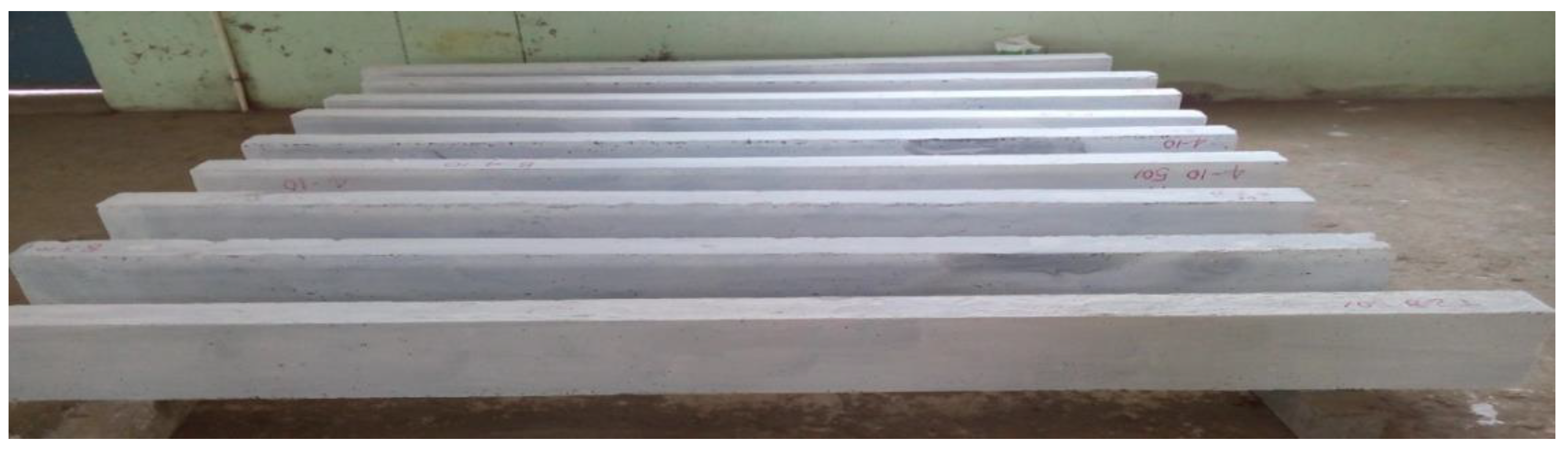
2.2. Fabrication of Sandwich Beams

Figure 1 shows the sequence of fabrication of sandwich beams. Stage I involved reinforcement caging, placing polystyrene in position with binding wires, and fixing of the steel wire mesh on three sides of the cages, as shown in Figure 1a. In stage II, the mold was prepared with steel plates. Oil was applied on the steel mold for the following reasons: easy removal, smooth surface finishes, and to minimize the surface adhesion. Plaster of Paris was applied for arresting the leakage of water in the small gaps of the mold while concreting. Stage III involved the placement of the first layer of concrete and leveling up to the concrete cover thickness (Figure 1b,c). In stage IV, the fabricated reinforcement cages were placed over the bottom layer, and self-compacting concrete was poured. Specimens were then removed from the mold and cured for 28 days. All the test specimens were whitewashed to monitor the crack propagation and to measure the crack width.

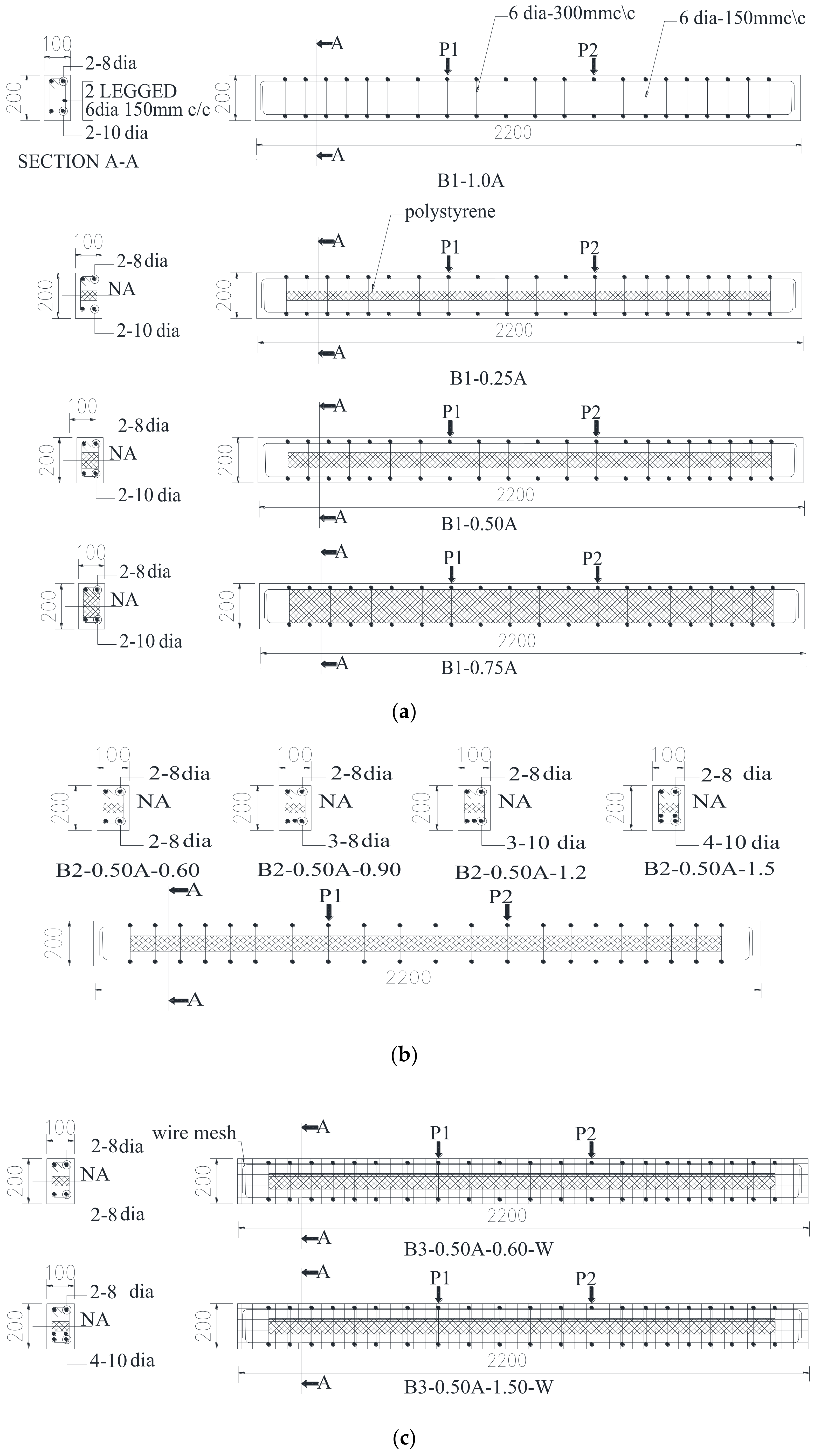
2.3. Details of the Test Specimens
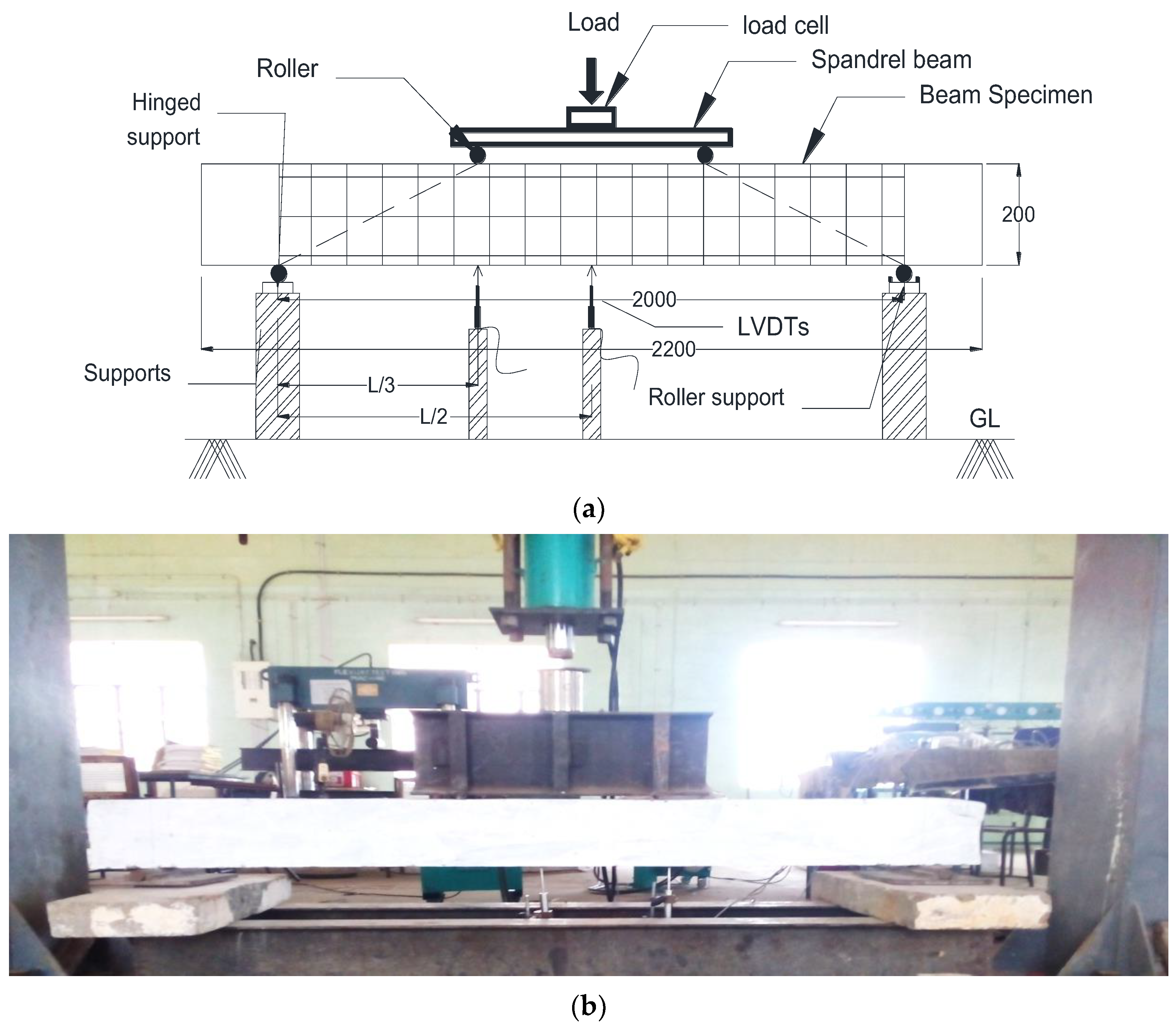
Details of the test specimens are shown in Figure 2. Ten beams were cast and tested in three different groups under four-point bending. The beam designation, geometry of the inner and outer core, and reinforcement details of solid and sandwich beams are given in Table 1. In the first group, four beams were tested with the inner core area varied by 0.0% (control beam), 25%, 50%, and 75%. The second and third group consisted of four and two beams, respectively, with a 50% inner core area. The tension reinforcement was varied as 0.6%, 0.9%, 1.2%, and 1.5% in the second group, whereas in the third group, wire meshes were provided at the top and bottom for beams with 0.6% and 1.5% of tension reinforcement. In the beam designation, “B1, B2, and B3” represent beam groups I, II, and III, respectively. The notations “0.00A, 0.25A, 0.50A, and 0.75A” correspond to zero, twenty-five, fifty, and seventy-five percent of inner core area. Furthermore, the last number represents the percentage of tension reinforcement, and “W” refers to the presence of wire mesh. Wire mesh is provided on the side faces and bottom face to resist shear and flexure, respectively. Classifications of beams and remarks are detailed in Table 2.

2.4. Test Setup

Specimens were tested in a 500 kN capacity loading frame. The schematic diagram of the test setup is shown in Figure 3. A spreader beam was used to distribute the applied concentrated load to the two-point loads on the top face of the beam. Each specimen was supported on roller and hinge assemblies. In the roller end, the displacement of the specimen in the transverse direction was restricted, whereas, at the hinged end, rotation was allowed. To achieve uniform contact between the specimen and the bearing plates, a thin layer of mortar was applied on the specimen as well as to the bearing plates. Two linear variable differential transformers (LVDTs) were placed at one-third span and mid-span from the left support. Strain gauges were mounted on the tension reinforcement at the mid-span. The transverse deflection, applied load, and strain were monitored through an assembly of a data logger in association with the load cell, LVDTs, and strain gauges, respectively.
The flexural test on reinforced concrete structures under four-point bending was conducted according to ASTM C 160 [55]. The whitewashed test specimen was placed on the supports and the horizontal and vertical alignments were checked with the mini laser projector. The LVDTs were checked and calibrated before applying the load. Initially, in order to check all the instruments were ready for the measurements, a 1 kN load was applied and corresponding deflection values were noted in each of the LVDTs. A handheld microscope was used to measure the crack width. Cracks in accordance with the applied load were marked on the surface of the specimen. When excessive cracking occurred, the failure load was identified. In addition, the load–deflection response dropped when the load increased beyond the ultimate load.

3. Results and Discussions

3.1. Test on Self-Compacting Concrete

The fresh and hardened properties of trial concrete mixes are presented in Table 2. The V-funnel, J-ring, slump flow, L-box, and U-box tests carried out on SCC mixes are shown in Figure 4. In view of the flow of concrete, both types of superplasticizers performed well; however, SCC mixes made of Conplast with a water-to-cement ratio of 0.33 exhibited maximum compressive strength. Consequently, the same ratio was adopted to prepare the sandwich beams. The cube compressive strength corresponding to each beam is given in Table 2.
The mechanical strength and serviceability results from each of the tests are presented in Table 3. Failure modes, cracking load ( V c r T E S T ), ultimate load ( V u T E S T ), initial cracking moment (Mcr), yielding moment (My), ultimate moment (Mu), and reserve strength index (R) were mechanical-strength-based results. On the other hand, maximum deflection ( Δ u l t ) and energy absorption (Eabs) were serviceability-based results.

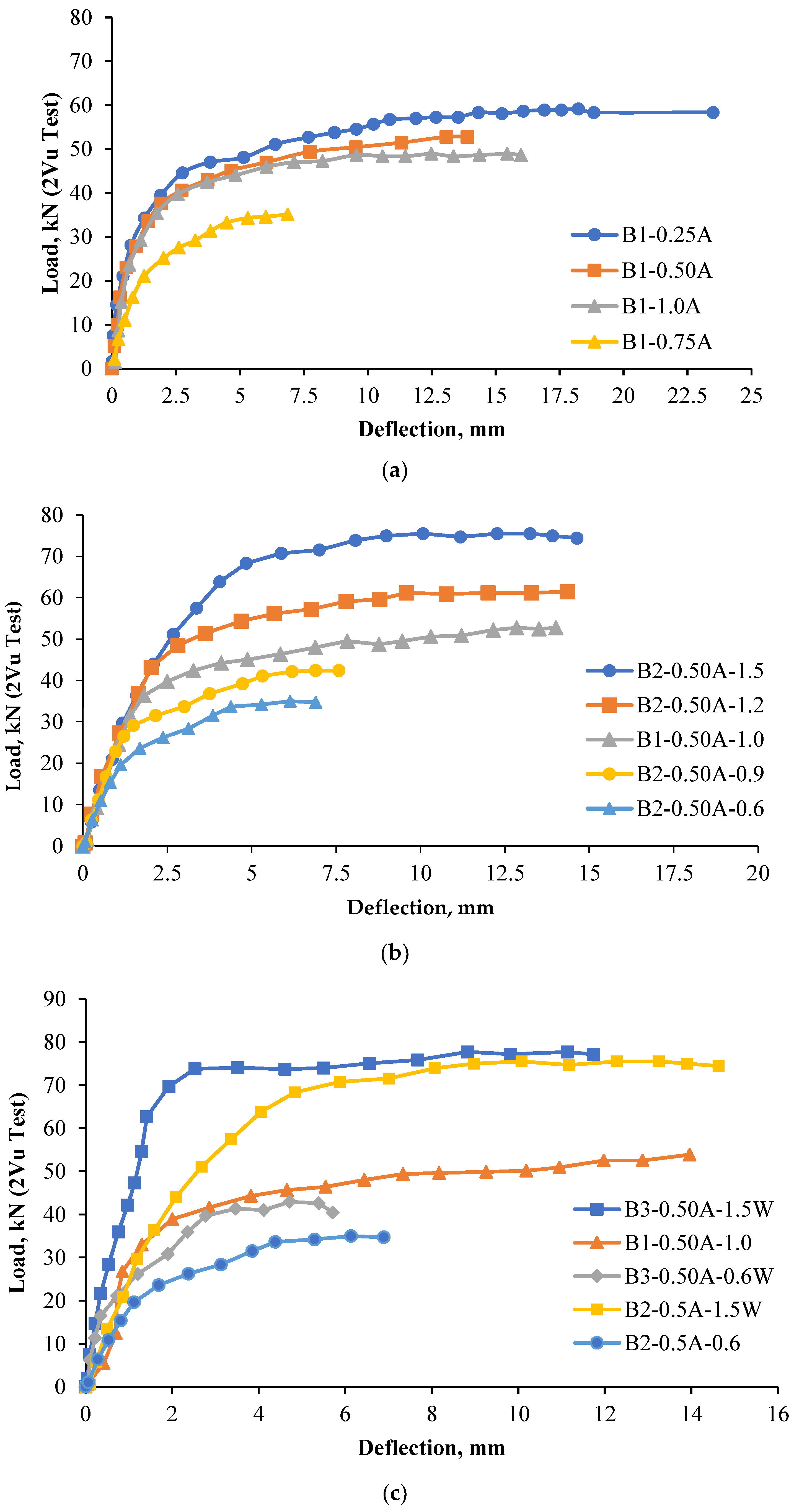
3.2. Load–Deflection Response

All cast specimens are shown in Figure 5. The load–deflection responses of test beams are shown in Figure 6. First, at zero external load, the beams carried their self-weight along with that of the loading system. When the load reached 31 to 60% of the failure load, tensile stresses at the bottom fiber reached the same magnitude as the modulus of rupture of concrete. Up to the cracking load, the load–deflection response of beams varied linearly as the strain in steel and concrete was relatively small, and the materials were under an elastic range. As the load increased beyond the cracking load, tensile stresses in the concrete were greater than the modulus of rupture of concrete; thus, cracks were further developed. Then, the response seemed to be nonlinear up to the yielding moment due to cracking, which resulted in the reduction in effective moment of inertia for the applied load. As the load increased further, strain-hardening occurred, and the beams reached their ultimate load [56]. In the load–deflection curves, initial stiffness was a function of compressive strength of concrete, and the stiffness of nonlinear and constant regions relied on the grade and quantity of steel reinforcement. In beams, a large increase in deflection, prior to the failure, was indicative of ductile failure. Shear strength increased up to the first yielding and, after that, the crack width was increasing [57]. Up to the first crack, the shear strength was provided by the concrete. Moreover, the actual failure was due to the yielding of tension reinforcement [58].
In group 1, the initial uncracked stiffness of beams, namely, B1-1.0A, B1-0.25A, and B1-0.50A, were higher than that of B1-0.75A. Due to higher moment of inertia, the beams with larger thickness in the compression zone had a higher initial stiffness than the other beams with lower thickness. Initial uncracked stiffness was calculated by extending a line from the origin to the point at which the initial flexural crack occurred. In addition, the load–deflection curves were linear up to this point. The beam B1-0.25A deflected the most compared to all other beams at the ultimate load. The ultimate deflection of B1-0.25A was 21.58, which was 22.96% higher than that of the control specimen. In group 2, the beams with a high steel reinforcement ratio had exhibited a stiffer response and higher yielding and ultimate loads. The span-to-maximum deflection ratio of beams provided with a percentage of tension reinforcement more than 0.9% was merely the same and ranged between 93 and 328. Depending on the quantity of tension reinforcement (0.6–1.5%), each beam in group 2 showed different responses after yielding; however, the response was linear up to the yield load. Further, in group 3, the addition of steel wire mesh had improved the stiffness and ductility. The mesh provided in the side wythes and bottom wythes enhanced the initial stiffness, cracking, yield, and ultimate loads of sandwich beams.

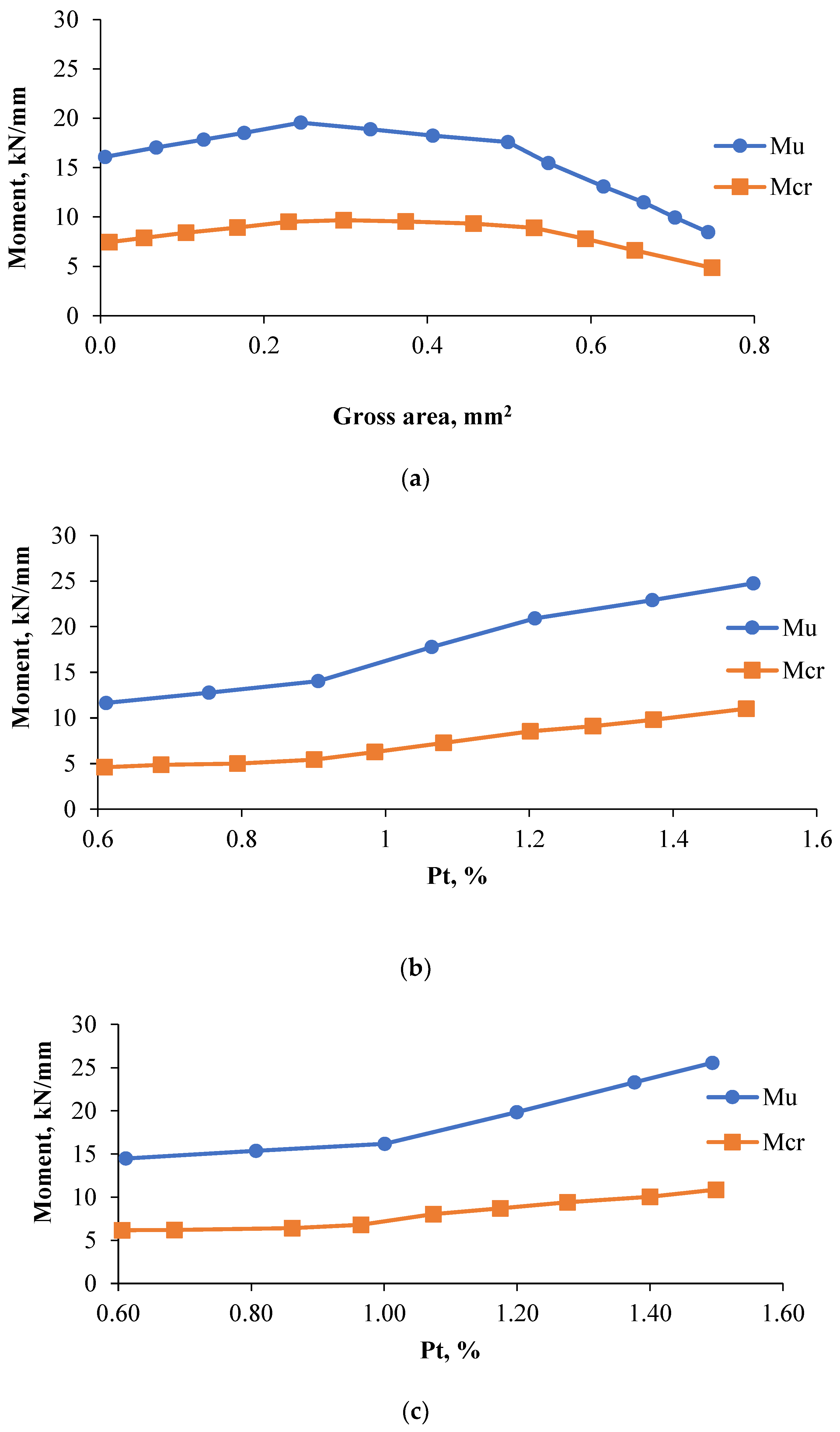
3.3. Moment Resistance

The moment of resistance of solid and sandwich beams is shown in Figure 7. When compared to the solid beam, the moment of resistance of sandwich beams increased up to 20% and 8% as the longitudinal inner core area reduced by 25% and 50%, respectively. A further decrease in inner core area by 75% reduced the flexural capacity by 49% of the solid beam. The area of the core influences considerably the ultimate moment carrying capacity. As the core thickness increases, the moment carrying capacity increases [59]. An increased core thickness reveals a minimal sandwich face yield. The core thickness increases the collapse load [60]. It is reported that when the size of inner core area increased, the percentage of tension reinforcement (Pt = Ast/Anet) was also increased; therefore, the ultimate moment of sandwich beams B1-0.25A and B1-0.50A was higher than that of the solid beam B1-1.0A. In group 2, the ultimate moment of beams B2-0.50A-0.60 and B2-0.50A-0.90 decreased by 28 and 12% with respect to the solid beam, respectively. On the other hand, the ultimate moment capacity of beams B2-0.50A-1.2 and B2-0.50A-1.5 increased to 31 and 55% of the moment capacity of the solid beam. By introducing the wire mesh, the moment capacity was decreased by 10% and increased up to 60% in cases of B3-0.50A-0.60-W and B3-0.50A-1.50-W, respectively. It should be noted that the counterparts of the moment capacity of group 3 beams as in group 2 without the wire mesh were decreased by 28% and increased by 55% with respect to the control beam. Furthermore, in between 31–60% and 58–86% of the applied moment, the concrete and reinforcement of sandwich beams cracked and yielded, respectively. The average cracking and yielding moments were 44 and 78% of the applied moment, respectively.
The process of selecting an optimum section was based on the ultimate load-to-the-net area of the concrete cross-section of beams. It is nothing but a strength-to-weight concept. In test beams, the length of the specimens had been maintained constant. On the other hand, the area of the inner core of the cross-section of beams was varied. The net cross-sectional area of concrete decreased with an increase in the area of inner core. As the area of the inner core increased, the ultimate load-to-area of the concrete cross-section of beams (strength-to-weight ratio) increased. The optimum section was determined by comparing and concluding the highest ultimate load-to-area of the concrete cross-section among other beams. The moment-to-weight ratio of sandwich beams was in between 17 and 113% higher than that of the solid beam, except for the beams B1-0.75A and B2-0.50A-0.60. Therefore, it was observed that when the maximum inner core area was 50% and the minimum tension reinforcement was 0.9%, the bending strength reached its optimal level when compared to the solid beam.

3.4. Reserve Strength Index

The reserve strength index is the ratio of the difference between the ultimate load and initial cracking load to the ultimate load. In simple words, it is the additional strength beyond the initial cracking load. The reserve strength increased by 27% and decreased by 26% in sandwich beams B1-0.25A and B1-0.75A with respect to the control beam, respectively. In group 2, the reserve strength decreased from 15% to 3% when the percentage of tension reinforcement ratio was increased from 0.9% to 1.5%. The beams provided with the wire mesh, in addition to 0.6 and 1.5% of tension reinforcement, performed better than those counterparts in group 2 as well as the control beam. From the experimental results, it can be concluded that the reserve strength of sandwich beams decreased with the quantity of tension reinforcement and, consequently, the mode of failure changed from flexure to flexural-shear or shear.

3.5. Energy Absorption

The area under the load–deflection response is considered as the energy absorption, and it can be calculated using the trapezoidal rule as given in Equation (1):
A = V n i + V n i + 1 Δ i + 1 Δ i 2
where V n i + 1 and   V n i are the load ordinates of beams corresponding to the deflections Δ i + 1   and     Δ i , respectively. The energy absorption of beams, namely, B1-0.25A, B2-0.50A-1.2, B2-0.50A-1.5, and B3-0.50A-1.5W, were 43, 12, 35, and 17% higher than that of the solid beam, respectively. In group 2, the beams with tension reinforcements of 0.6 and 0.9% exhibited energy absorptions of 75 and 65% lower than that of the solid beam, whereas the beams with tension reinforcements of 1.2 and 1.5% showed 12 and 35% higher energy absorptions than that of the control beam, respectively. One of the previous studies showed a 35% increase in energy absorption due to the inner core; at the same time, due to the provision of face sheets, the energy absorption decreased by 30%. In group 3, for the beams with 0.6% and 1.5% tension reinforcements, the energy absorptions decreased by 73% and increased by 17%, respectively. When the tension reinforcements provided in the sandwich beams were higher than those of the solid beams, it was found that the energy absorption of sandwich beams was higher than that of the solid beam. Due to the presence of a polystyrene foam core, the failure mechanism showed that the collapse of the structure was a slow rate of progressive collapse, which results in a high energy absorption capacity [61]. The addition of steel wire mesh improved the energy storing capacity of the sandwich beams. Although the tension reinforcement percentage increased as the inner core area decreased in group 1, the energy stored was decreased beyond its optimum range for beams with a 50% inner core area.

3.6. Deflection

The excessive cracking of concrete affects the appearance and durability of the structural members. Therefore, the Indian standard imposes a limit that the maximum deflection should not exceed the lesser of span/350 or 20 mm. Amongst all the beams, only one beam, namely, B1-0.25A, exceeded the deflection limit of 20 mm at the ultimate moment. Meanwhile, in the deflection check, the ranges of the effective span-to-maximum deflection of other beams were 93–262, 124–321, and 153–328, corresponding to group 1, 2, and 3, respectively. For example, if the limiting value of span-to-deflection was 250, then four beams, namely, B1-0.75A, B2-0.50A-0.6, and B3-0.50A-0.6-W, failed in the serviceability limit state. This indicates that the deflection of sandwich beams with a low amount of tension reinforcement and low thickness of the outer core exceeded the acceptable limit, and therefore, serviceability failure occurred. Except for beam B1-0.25A, all other sandwich beams deflected lesser than that of the control beam at a range between 8 and 65%.

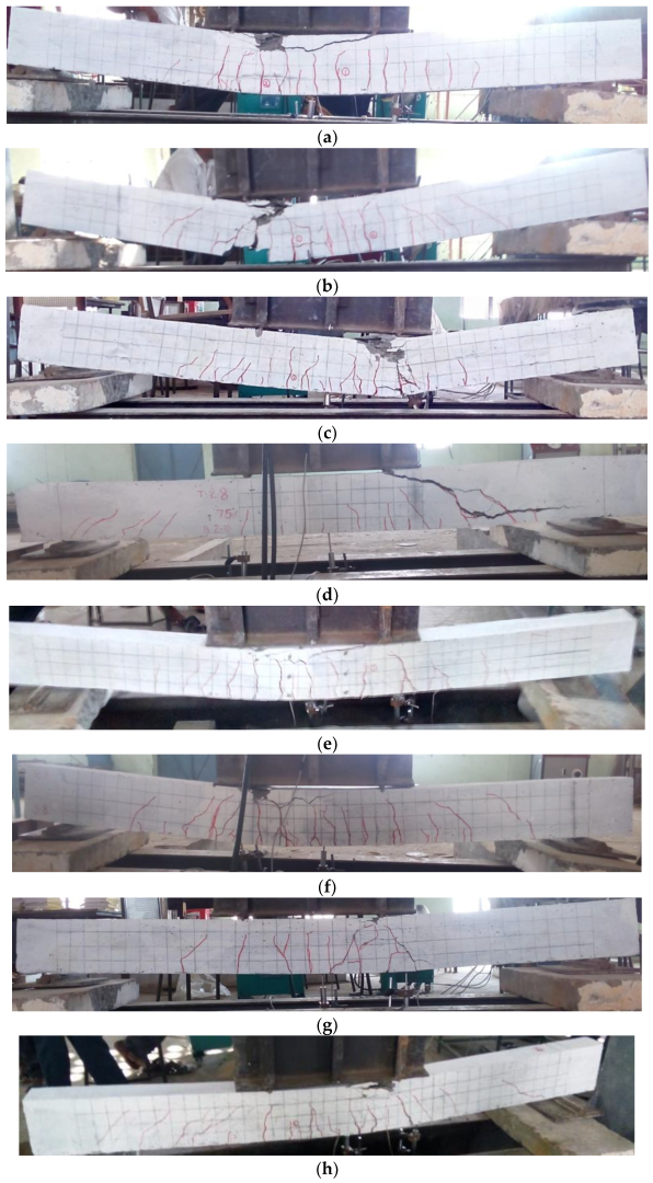
4. Failure Modes and Failure Mechanism

As the applied moment on the sandwich beam section increased beyond the initial cracking phase, the stress was concentrated near the crack tip. The cracks initiated at the soffit of the beam, and with increased loading, the cracks widened and propagated gradually toward the neutral axis [62]. The cracks started to open when the stress at the tip reached the tensile strength limit. The cracked concrete was ineffective in resisting the tensile stresses. Therefore, the concrete below the neutral axis was merely useless, except for serving two functions: (1) holding the rebars in place and (2) resisting the shear and torsion [63].
The failure modes of test specimens are shown in Figure 8. All the beams failed in flexure except beam B1-0.75A, which failed in shear. In the control beam, enough percentage of tension reinforcement was provided to manifest the flexural compression failure. Meanwhile, beams B1-0.25A and B1-0.50A have also shown combined failure, i.e., concrete crushed in the compression zone and steel reinforcement yielded in tension. In beam B1-0.75A, shear stress increased at a distance of “d” from the support and caused diagonal cracks. The shear cracks developed and extended to the level of tension reinforcement and then propagated horizontally toward the support [64].
In group 1, the net outer-core concrete area (Anet) decreased when inner-core area varied from 0.00% to 75% of the gross area, resulting in an increase in tension reinforcement ratio. It should be noted that the gross area and reinforcement configuration were constant in beams belonging to group 1. When the quantity of tension reinforcement was increased, the couple ( f y A s t × l e v e r   a r m ,   z ) resisting the flexural stresses increased. Another reason the moment capacity of sandwich beams was higher than the solid beam could be explained through the fracture mechanics approach. According to the principles of fracture mechanics, stress near the crack tip tends to infinity, regardless of the type and magnitude of the load. Cook’s theory reports that if a weak interface or cleavage is present roughly normal to the plane of the main crack, then the interface may break, producing a secondary crack, and the progress of the primary crack will be curbed [65]. Likewise, the inner core is merely hollow, hindering the growth of the flexural crack. Only half of the energy flowed to the crack tip in the side covered beyond the thickness of the bottom wythe, where it was dissipated by the facture process. Therefore, it was found that the moment carrying capacities of sandwich beams were higher than those of the solid beams [66].
In the second group of beams, as the amount of tension reinforcement increased, the number of cracks distributed along the span increased (Figure 5). Shear cracks appeared when the beams were provided with a higher amount of tension reinforcement (1.2 and 1.5%). For the beams provided with a 1.5% tension reinforcement, inclined cracks joined together to form the diagonal tension cracks. In addition, the mode of failure changed from flexure to flexural-shear due to the following reasons: high flexural rigidity due to the provision of 1.5% of tension reinforcement, and the width of side cover was insufficient to resist the shear stresses. In group 3, the beams with steel wire mesh failed in flexure, in which the concrete crushed due to flexural compression. As the percentage of tension reinforcement increased due to the addition of steel wire mesh, the number of visible distributed cracks increased.

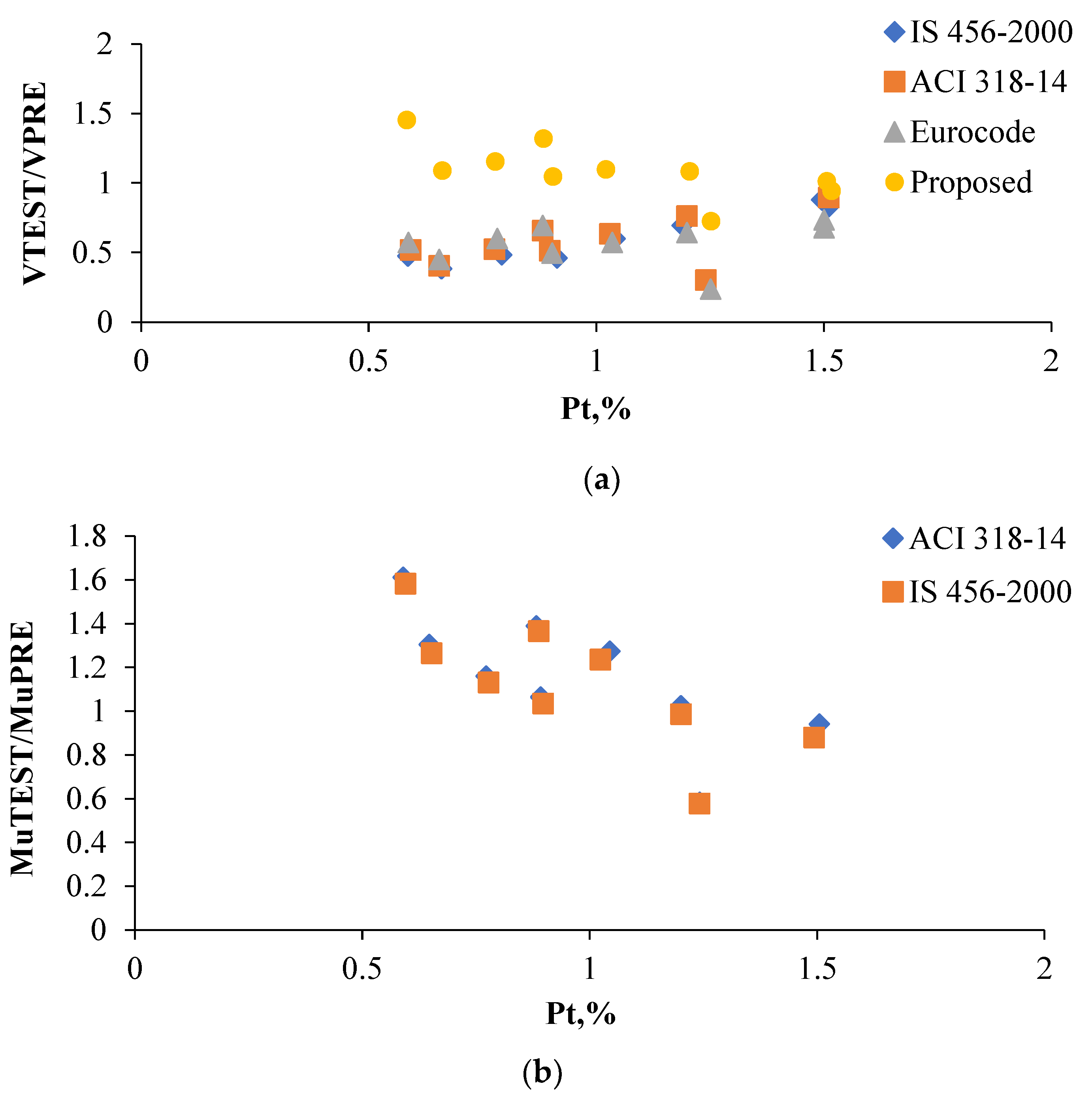
5. Prediction in Accordance with the Existing Expressions

The expressions to predict the shear and flexural strength of solid RC beams according to IS456-2000 [67], ACI318-14 [68], and Eurocode 2 [69] are listed in Table 4. The experimental results were compared with the moment and shear strengths obtained from the expressions given in the codes of practice. The plot of shear strength ratio, V n T E S T V n P R E , against the percentage of tension reinforcement and the plot of moment ratio, M u T E S T M u P R E , against the percentage of tension reinforcement are shown in Figure 7(a,b), respectively. The IS456-2000 and American codes predict the moment capacity of sandwich beams in a range of 88 to 109% and 87 to 112% of experimentally measured bending moments, respectively (excluding beam B1-0.75A, which failed in shear). Furthermore, the moment of resistance expression of the ACI code is slightly conservative compared to the Indian standard as the stress block is considered as a rectangle rather than a parabola. The mean, standard deviation, and coefficient of variation of moment ratios calculated from the guidelines of Indian and American codes are 1.09, 0.28, and 25% and 1.11, 0.28, and 25%, respectively. The comparison results indicate that the flexural strength expressions available in the current design codes, which are derived from the classical Bernouli’s theorem, are valid for the sandwich beams. On the other hand, the mean values of shear strength ratios of Indian, American, and European codes are 0.56, 0.60, and 0.55, respectively. The shear strength of sandwich beams is overestimated by these codes. The reason for this overestimation and the proposed refinement for shear strength expression is explained in the following section.

6. Modified Shear Strength Expressions

Based on the shear failure mechanism of sandwich beams, an analytical equation was formulated from the ACI shear strength expression. The shear force is normally resisted by uncracked concrete, the vertical component of the aggregate interlock, dowel action, and the web reinforcement. The ultimate shear resistance by any section of the beam is given by Equation (2):
V = V c + V s
where the total shear resistance of the beam is given by V, the ultimate shear resistance of concrete is V c , and the ultimate shear resistance of vertical stirrups is V s . As per ACI 318-14, 0.17 f c can be substituted instead of 0.158 f c + 0.17   ρ w V u D M u in the expression of Vc. Thus, Vc can be calculated as per Equation (3).
V c = 0.158 f c + 0.17   ρ m V u D M u b d 0.17 f c b d
The design strength of concrete, 0.17 f c bd, is rewritten as 0.17 f c ρ w 2 A n e t for the following reasons. First, for neglecting the inertness of polystyrene in structural behavior, Agross is replaced by Anet (outer core area). Secondly, the effect of tension reinforcement percentage ( ρ m ) on the shear strength is incorporated in the ultimate shear resistance of concrete by multiplying 0.17 f c A n e t with ρ m 2 .
V s = n s f y s A v s
The term f y s A v s in Equation (4) is the internal force component offered by the stirrups. Total force is the product of the total number of bars and the force in each bar. To obtain the number of bars effectively contributing toward shear resistance, the term “ d tan θ ” is multiplied by “ F 1 1 S v ”, where the horizontal length of the diagonal crack is “ d tan θ ”. The mitigation factor for the shear critical member, F 1 = 1 + α l n d 12 , is adopted from the ACI 318 code [68]. There are two reasons for considering the mitigation factor. First, the shear reinforcement may not yield at the ultimate loads. Secondly, the inclination of the shear crack of sandwich beams is greater than 45°; therefore, all the vertical web bars do not contribute completely toward the diagonal tension resistance. However, the fundamental assumption of codes such as American, Indian, and European codes is that the inclination of the shear crack is 45°.
The number of vertical bars in Equation (4) is n v = F 1 d s v tan θ . For beams with an a/d ratio greater 2.0, adopting the inclination of the crack, tan θ = d a yields unconservative results. Instead, the shear crack angle can be idealized as tan θ = d S v . As a result, the general form of the shear strength expression by substituting the values of V C   and V V s in Equation (3) is given below.
V n P R O = 0.17 f c ρ m 2 A n e t + 1 + 0.4 l d 12 f y A s v D S v tan d s v
where V is the shear strength of sandwich beams; Anet is the net area of concrete; ρ s v is the percentage of vertical steel wires; ρ s v is the percentage of vertical web reinforcement; f c ' is the cylinder compressive strength of concrete; l n d   is   the   effective span-to-depth ratio. Using regression analysis of the experimental data, α is found to be 0.4 for conservative results.
The expressions to predict the shear and flexural strength of solid RC beams according to IS456-2000 [67], ACI318-14 [68], and Eurocode 2 [69] are listed in following Table 4.
Table 4. Existing models to predict shear strength and moment of resistance.
Sl. NoModelsCodes of PracticeExpressionsEquation No
1.Shear strength expressionsIS 456-2000 V n I S = Vc + Vs
V c = τ c × A n e t ;
τ c = 0.85 0.8   f c k 1 + 5 α 1 6 α ;
α = = 0.8 f c k 6.89   P t = 1 w h i c h e v e r i s g r e a t e r ;
Vs = 𝑓𝑦𝐴𝑠𝑣D/Sv
(6)
2.ACI 318-08 V n A C I = 0.158 f c + 0.17   ρ w V u D M u A n e t + f y A s v D S v (7)
3.Eurocode 2 V n E C = τ R k 1.2 + 40 ρ w + 0.9 ρ v f y v A n e t
τ R = 0.25   0.7 × 0.30 × 0.8 × f c k 2 3 ;
k = 1.6 D 1.0   ;   ρ w = A s A n e t ;   ρ v   = A s v B b S v
(8)
4.Moment of resistanceIS 456-2000 M n I S = A s f y d 1 A s f y A n e t f c k (9)
5.ACI 318-08 M n A C I = A s f y d 1 A s f y 0.85 f c A n e t 2 (10)

7. Reliability of the Modified Shear Strength Expression

The analytical equation proposed here was validated against the results of 10 sandwich beam tests. The proposed shear strength equation predicts the capacity of sandwich beams within the range of 71% to 111% of the experimentally measured shear strength with a mean value of the shear strength ratio of 1.0. The coefficient of variation is 14%. Irrespective of the tension reinforcement ratio, the proposed equation showed a uniform prediction. As no experimental data are available in the literature with an a/d ratio greater than 2.0, the proposed equation was validated with only 10 beam results presented in this study. In the future, more experimental studies are needed to understand the behavior of sandwich beams with a span-to-depth ratio between 6 and 10. Figure 9 represents the graph between mechanical strength ratio and percentage of tension reinforcement.

8. Conclusions

In this study, an optimum geometry and reinforcement ratio were determined for a sandwich beam comprising a polystyrene inner core with wire mesh reinforcement, and the influence of the inner core area and the effect on providing a wire mesh were analyzed. The experimental results were compared with the shear strength and moment of resistance expressions suggested by the current design codes such as Indian, American, and European codes. Based on the comparison results, a modified model was presented and has the potential to enable the design engineers to evaluate the shear capacity of such sandwich beams. From the results of this study, the following conclusions were drawn:
The moment of resistance of sandwich beams increased up to 20% and 8% as the longitudinal inner core area reduced by 25% and 50%, respectively.
The experimental results proved that the performance of the sandwich beam was better than the normal beam in regard to the mechanical strength-to-weight ratio and serviceability aspect. For achieving high bending strength and stiffness, the optimum limit for adopting the inner core area was 50% and the minimum tension reinforcement was 0.9%.
The moment-to-weight ratio of sandwich beams was in between 17 and 113% higher than that of the solid beam.
As the area of the inner core increased for a given reinforcement configuration and geometry, the failure mode of sandwich beams changed from flexure to shear.
The load-carrying capacity of sandwich beams increased with the quantity of flexural reinforcements. In addition, the welded wire meshes improved the flexural and shear performances of sandwich beams.
The conventional expressions for the moment of resistance were valid for predicting the moment capacity of sandwich beams, whereas the shear strength expressions available in the current design standards overestimated the shear strength of such sandwich beams. Therefore, design modifications were proposed for the better prediction of shear strength. The proposed shear strength design formula could closely predict the experimental shear strength of sandwich beams and, therefore, can be used by future researchers and by practicing engineers.

Author Contributions

Conceptualization, V.C. and L.R.J.; data acquisition, V.C., L.R.J., S.A., and D.R.; formal analysis, V.C., L.R.J., S.A., D.R., M.A. and P.G.; funding acquisition, S.A., M.A., R.F. and N.I.V.; investigation, V.C., D.R. and L.R.J.; methodology, V.C., L.R.J. and S.A.; project administration, V.C., L.R.J., S.A., D.R., M.A., P.G. and K.R.; software, V.C., L.R.J., S.A., D.R., M.A., P.G., K.R., R.F. and N.I.V.; validation, V.C., L.R.J., S.A., D.R., M.A., P.G., K.R., R.F. and N.I.V.; visualization, V.C., L.R.J., S.A., D.R., M.A. and P.G.; writing—original draft, V.C. and D.R.; writing—review and editing, V.C., L.R.J., S.A., D.R., M.A., P.G., K.R., R.F. and N.I.V. All authors have read and agreed to the published version of the manuscript.

Funding

The research is partially funded by the Ministry of Science and Higher Education of the Russian Federation under the strategic academic leadership program ‘Priority 2030’ (Agreement 075-15-2021-1333 dated 09/30/2021).

Institutional Review Board Statement

Not applicable.

Informed Consent Statement

Not applicable.

Data Availability Statement

Data sharing not applicable.

Acknowledgments

The authors wish to acknowledge the support by the A.C Government College of Engineering and Technology, Karaikudi, India and CSIR-Northeast Institute of Science and Technology, Jorhat, Assam, India. Centro Nacional de Excelencia para la Industria de la Madera (ANID BASAL FB210015 CENAMAD), Pontificia Universidad Católica de Chile, Vicuña Mackenna 7860, Santiago, Chile. The author thanks Vicerrectoria de Investigacion y Desarrollo (VRID) y Direccion de Investigacion y Creacion Artistica DICA, Proyecto presentado al Concurso VRID-Iniciación 2022, VRID N°2022000449-INI, Universidad de Concepción, Concepción, Chile. The authors also gratefully acknowledge the financial support given by the Deanship of Scientific Research at Prince Sattam bin Abdulaziz University, Alkharj, Saudi Arabia, for this research.

Conflicts of Interest

The authors declare no conflict of interest.

References

  1. Mugahed Amran, Y.H. Determination of Structural Behavior of Precast Foamed Concrete Sandwich Panel. Ph.D. Thesis, Universiti Putra Malaysia (UPM), Seri Kembangan, Malaysia, 2016. [Google Scholar]
  2. Mugahed Amran, Y.H.; El-Zeadani, M.; Huei Lee, Y.; Yong Lee, Y.; Murali, G.; Feduik, R. Design innovation, efficiency and applications of structural insulated panels: A review. Structures 2020, 27, 1358–1379. [Google Scholar] [CrossRef]
  3. Zhou, Y.; Gao, H.; Hu, Z.; Qiu, Y.; Guo, M.; Huang, X.; Hu, B. Ductile, durable, and reliable alternative to FRP bars for reinforcing seawater sea-sand recycled concrete beams: Steel/FRP composite bars. Constr. Build. Mater. 2021, 269, 121264. [Google Scholar] [CrossRef]
  4. Liang, Z.; Hu, Z.; Zhou, Y.; Wu, Y.; Zhou, X.; Hu, B.; Guo, M. Improving recycled aggregate concrete by compression casting and nano-silica. Nanotechnol. Rev. 2022, 11, 1273–1290. [Google Scholar] [CrossRef]
  5. Zhou, Y.; Weng, Y.; Li, L.; Hu, B.; Huang, X.; Zhu, Z. Recycled GFRP Aggregate Concrete Considering Aggregate Grading: Compressive Behavior and Stress–Strain Modeling. Polymers 2022, 14, 581. [Google Scholar] [CrossRef]
  6. Arularasi, V.; Pachiappan, T.; Avudaiappan, S.; Raman, S.N.; Guindos, P.; Amran, M.; Fediuk, R.; Vatin, N.I. Effects of Admixtures on Energy Consumption in the Process of Ready-Mixed Concrete Mixing. Materials 2022, 15, 4143. [Google Scholar] [CrossRef] [PubMed]
  7. Makul, N.; Fediuk, R.; Amran, M.; Zeyad, A.M.; Murali, G.; Vatin, N.; Klyuev, S.; Ozbakkaloglu, T.; Vasilev, Y. Use of recycled concrete aggregates in production of green cement-based concrete composites: A review. Crystals 2021, 11, 232. [Google Scholar] [CrossRef]
  8. Mugahed Amran, Y.H.; Abang Ali, A.A.; Rashid, R.S.M.; Hejazi, F.; Safiee, N.A. Structural behavior of axially loaded precast foamed concrete sandwich panels. Constr. Build. Mater. 2016, 107, 307–320. [Google Scholar] [CrossRef]
  9. Amran, Y.H.M.; Rashid, R.S.M.; Hejazi, F.; Safiee, N.A.; Ali, A.A.A. Response of precast foamed concrete sandwich panels to flexural loading. J. Build. Eng. 2016, 7, 143–158. [Google Scholar] [CrossRef]
  10. Akmaluddin, A.; Murtiadi, S.; Anshari, B. Flexural stiffness of normal and sandwich reinforced concrete beam exposed to fire under fixed loading. Int. Rev. Civ. Eng. 2020, 11, 36–44. [Google Scholar] [CrossRef]
  11. Birman, V.; Kardomateas, G.A. Review of current trends in research and applications of sandwich structures. Compos. Part B Eng. 2018, 142, 221–240. [Google Scholar] [CrossRef]
  12. Sapuan, S.M.; Aulia, H.S.; Ilyas, R.A.; Atiqah, A.; Dele-Afolabi, T.T.; Nurazzi, M.N.; Supian, A.B.M.; Atikah, M.S.N. Mechanical properties of longitudinal basalt/woven-glass-fiber-reinforced unsaturated polyester-resin hybrid composites. Polymers 2020, 12, 2211. [Google Scholar] [CrossRef]
  13. Asyraf, M.R.M.; Rafidah, M.; Ishak, M.R.; Sapuan, S.M.; Yidris, N.; Ilyas, R.A.; Razman, M.R. Integration of TRIZ, morphological chart and ANP method for development of FRP composite portable fire extinguisher. Polym. Compos. 2020, 41, 2917–2932. [Google Scholar] [CrossRef]
  14. Ashraf, W.; Ishak, M.R.; Zuhri, M.Y.M.; Yidris, N.; Ya’Acob, A.M. Experimental Investigation on the Mechanical Properties of a Sandwich Structure Made of Flax/Glass Hybrid Composite Facesheet and Honeycomb Core. Int. J. Polym. Sci. 2021, 2021, 8855952. [Google Scholar] [CrossRef]
  15. Gara, F.; Ragni, L.; Roia, D.; Dezi, L. Experimental behaviour and numerical analysis of floor sandwich panels. Eng. Struct. 2012, 36, 258–269. [Google Scholar] [CrossRef]
  16. Daniel Ronald Joseph, J.; Prabakar, J.; Alagusundaramoorthy, P. Flexural behavior of precast concrete sandwich panels under different loading conditions such as punching and bending. Alex. Eng. J. 2018, 57, 309–320. [Google Scholar] [CrossRef]
  17. Poluraju, P.; Appa Rao, G. Performance of squat 3D sandwich walls with longitudinal reinforcement and boundary elements under lateral cyclic loading. J. Sandw. Struct. Mater. 2018, 20, 946–973. [Google Scholar] [CrossRef]
  18. Raj J, L.; Rao G, A. Load configuration, geometry and web reinforcement effects on failure modes of sandwich deep beams. J. Sandw. Struct. Mater. 2018, 20, 811–830. [Google Scholar] [CrossRef]
  19. Mugahed Amran, Y.H.; Rashid, R.S.M.; Hejazi, F.; Abang Ali, A.A.; Safiee, N.A.; Bida, S.M. Structural Performance of Precast Foamed Concrete Sandwich Panel Subjected to Axial Load. KSCE J. Civ. Eng. 2018, 22, 1179–1192. [Google Scholar] [CrossRef]
  20. Amran, Y.M.; Rashid, R.S.; Hejazi, F.; Safiee, N.A.; Ali, A.A. Structural behavior of laterally loaded precast foamed concrete sandwich panel. Int. J. Civ. Environ. Struct. Constr. Arch. Eng. 2016, 10, 255–263. [Google Scholar]
  21. Amran, Y.M.; Rashid, R.S.; Hejazi, F.; Safiee, N.A.; Ali, A.A. Structural behavior of precast foamed concrete sandwich panel subjected to vertical in-plane shear loading. J. Civ. Environ. Struct. Constr. Arch. 2016, 10, 699–708. [Google Scholar]
  22. Basunbul, I.A.; Saleem, M.; Al-Sulaimani, G.J. Flexural behavior of ferrocement sandwich panels. Cem. Concr. Compos. 1991, 13, 21–28. [Google Scholar] [CrossRef]
  23. Petras, A.; Sutcliffe, M.P.F. Indentation failure analysis of sandwich beams. Compos. Struct. 2000, 50, 311–318. [Google Scholar] [CrossRef]
  24. Avilés, F.; Carlsson, L.A. Experimental study of debonded sandwich panels under compressive loading. J. Sandw. Struct. Mater. 2006, 8, 7–31. [Google Scholar] [CrossRef]
  25. Shipsha, A.; Hallstrom, S.; Zenkert, D. Failure mechanisms and modelling of impact damage in sandwich beams—A 2D approach: Part II—Analysis and modelling. J. Sandw. Struct. Mater. 2003, 5, 33–51. [Google Scholar] [CrossRef]
  26. Shipsha, A. Failure of Sandwich Structures With Sub-Interface Damage. KTH Stock. 2001, 17, 33. [Google Scholar]
  27. Rao, G.A.; Raj, J.L. Failure analysis of 3D sandwich beams under transverse shear. J. Struct. Eng. 2017, 44, 76–87. [Google Scholar]
  28. Benayoune, A.; Samad, A.A.A.; Trikha, D.N.; Ali, A.A.A.; Ellinna, S.H.M. Flexural behaviour of pre-cast concrete sandwich composite panel—Experimental and theoretical investigations. Constr. Build. Mater. 2008, 22, 580–592. [Google Scholar] [CrossRef]
  29. Bush, T.D.; Stine, G.L. Flexural Behavior of Composite Precast Concrete Sandwich Panels With Continuous Truss Connectors. PCI J. 1994, 39, 112–121. [Google Scholar] [CrossRef]
  30. Benayoune, A.; Samad, A.A.A.; Trikha, D.N.; Abang Ali, A.A.; Ashrabov, A.A. Structural behaviour of eccentrically loaded precast sandwich panels. Constr. Build. Mater. 2006, 20, 713–724. [Google Scholar] [CrossRef]
  31. Rezaifar, O.; Kabir, M.Z.; Taribakhsh, M.; Tehranian, A. Dynamic behaviour of 3D-panel single-storey system using shaking table testing. Eng. Struct. 2008, 30, 318–337. [Google Scholar] [CrossRef]
  32. Cuypers, H.; Wastiels, J. Analysis and verification of the performance of sandwich panels with textile reinforced concrete faces. J. Sandw. Struct. Mater. 2011, 13, 589–603. [Google Scholar] [CrossRef]
  33. Amran, M.; Abdelgader, H.S.; Onaizi, A.M.; Fediuk, R.; Ozbakkaloglu, T.; Rashid, R.S.; Murali, G. 3D-printable alkali-activated concretes for building applications: A critical review. Constr. Build. Mater. 2022, 319, 126126. [Google Scholar] [CrossRef]
  34. Lesovik, V.; Fediuk, R.; Amran, M.; Alaskhanov, A.; Volodchenko, A.; Murali, G.; Uvarov, V.; Elistratkin, M. 3D-Printed Mortars with Combined Steel and Polypropylene Fibers. Fibers 2021, 9, 79. [Google Scholar] [CrossRef]
  35. Klyuev, S.; Klyuev, A.; Fediuk, R.; Ageeva, M.; Fomina, E.; Amran, M.; Murali, G. Fresh and mechanical properties of low-cement mortars for 3D printing. Constr. Build. Mater. 2022, 338, 127644. [Google Scholar] [CrossRef]
  36. Siddika, A.; Shojib, M.H.H.; Hossain, M.M.; Hossain, M.I.; Mamun, M.A.A.; Alyousef, R.; Amran, Y.H.M. Flexural performance of wire mesh and geotextile-strengthened reinforced concrete beam. SN Appl. Sci. 2019, 1, 1324. [Google Scholar] [CrossRef] [Green Version]
  37. El-Zeadani, M.R.; Raizal Saifulnaz, M.R.; Mugahed Amran, Y.H.; Hejazi, F.; Jaafar, M.S.; Alyousef, R.; Alabduljabbar, H. Analytical mechanics solution for measuring the deflection of strengthened RC beams using FRP plates. Case Stud. Constr. Mater. 2019, 11, e00272. [Google Scholar] [CrossRef]
  38. El-Zeadani, M.; Raizal Saifulnaz, M.R.; Hejazi, F.; Mugahed Amran, Y.H.; Jaafar, M.S.; Alyousef, R.; Alrshoudi, F. Mechanics-based approach for predicting the short-term deflection of CFRP plated RC beams. Compos. Struct. 2019, 225, 111169. [Google Scholar] [CrossRef]
  39. Al-Nini, A.; Nikbakht, E.; Syamsir, A.; Shafiq, N.; Mohammed, B.S.; Al-Fakih, A.; Al-Nini, W.; Amran, Y.H.M. Flexural behavior of double-skin steel tube beams filled with fiber-reinforced cementitious composite and strengthened with CFRP sheets. Materials 2020, 13, 3064. [Google Scholar] [CrossRef] [PubMed]
  40. Rahim, N.I.; Mohammed, B.S.; Al-Fakih, A.; Wahab, M.M.A.; Liew, M.S.; Anwar, A.; Mugahed Amran, Y.H. Strengthening the structural behavior of web openings in RC deep beam using CFRP. Materials 2020, 13, 2804. [Google Scholar] [CrossRef]
  41. Bakar, M.B.C.; Muhammad Rashid, R.S.; Amran, M.; Saleh Jaafar, M.; Vatin, N.I.; Fediuk, R. Flexural Strength of Concrete Beam Reinforced with CFRP Bars: A Review. Materials 2022, 15, 1144. [Google Scholar] [CrossRef]
  42. El-Zeadani, M.; Rashid, R.S.M.; Amran, M.Y.H.; Swi, M.I. Effect of the plate bondstress-slip property on the flexural strength of FRP Plated RC beams using a displacement-based approach. SN Appl. Sci. 2020, 2, 1925. [Google Scholar] [CrossRef]
  43. Murali, G.; Amran, M.; Fediuk, R.; Vatin, N.; Raman, S.N.; Maithreyi, G.; Sumathi, A. Structural behavior of fibrous-ferrocement panel subjected to flexural and impact loads. Materials 2020, 13, 5648. [Google Scholar] [CrossRef] [PubMed]
  44. Raj, J.L.; Rao, G.A. Shear strength of rc deep beam panels—A review. Int. J. Res. Eng. Technol. 2014, 3, 89–103. [Google Scholar] [CrossRef]
  45. Praneeth, A.; Pramod Kumar, K.V.S.; Pramod, R.; Veeresh Kumar, G.B. Investigation of Mechanical properties of Glass Fibre Reinforced Honeycomb Panels. In Proceedings of the IOP Conference Series: Materials Science and Engineering, Bengaluru, India, 16–18 August 2018. [Google Scholar] [CrossRef] [Green Version]
  46. Saheed, S.; Aziz, F.N.A.A.; Amran, M.; Vatin, N.; Fediuk, R.; Ozbakkaloglu, T.; Murali, G.; Mosaberpanah, M.A. Structural performance of shear loaded precast EPS-foam concrete half-shaped slabs. Sustainability 2020, 12, 9679. [Google Scholar] [CrossRef]
  47. Saheed, S.; Amran, Y.H.M.; El-Zeadani, M.; Aziz, F.N.A.; Fediuk, R.; Alyousef, R.; Alabduljabbar, H. Structural behavior of out-of-plane loaded precast lightweight EPS-foam concrete C-shaped slabs. J. Build. Eng. 2021, 33, 101597. [Google Scholar] [CrossRef]
  48. El-Zeadani, M.; Raizal Saifulnaz, M.R.; Amran, M. Full-range bondstress-slip model for externally bonded FRP plates including a frictional component. Compos. Struct. 2021, 262, 113372. [Google Scholar] [CrossRef]
  49. Hassan, A.A.A.; Hossain, K.M.A.; Lachemi, M. Structural assessment of corroded self-consolidating concrete beams. Eng. Struct. 2010, 32, 874–885. [Google Scholar] [CrossRef]
  50. Choulli, Y.; Marí, A.R.; Cladera, A. Shear behaviour of full-scale prestressed i-beams made with self compacting concrete. Mater. Struct. Constr. 2008, 41, 131–141. [Google Scholar] [CrossRef]
  51. Hassan, A.A.A.; Hossain, K.M.A.; Lachemi, M. Behavior of full-scale self-consolidating concrete beams in shear. Cem. Concr. Compos. 2008, 30, 588–596. [Google Scholar] [CrossRef]
  52. Xu, G.; Li, A. Experimental and numerical studies on the lateral performance of concrete sandwich walls. Struct. Des. Tall Spec. Build. 2020, 29, e1715. [Google Scholar] [CrossRef]
  53. Bureau of Indian Standard(BIS) IS: 8112-1989; Specification for 43 Grade Ordinary Portland Cement. Bureau of Indian Standards: New Delhi, India, 2013.
  54. BIS:383; Specification for Coarse and Fine Aggregates from Natural Sources for Concrete. Bureau of Indian Standards: New Delhi, India, 1970.
  55. ASTM C1609/C1609M-19a; Standard Test Method for Flexural Performance of Fiber-Reinforced Concrete (Using Beam with Third-Point Loading). ASTM International: West Conshohocken, PA, USA, 2019.
  56. Ferdous, W.; Manalo, A.; Aravinthan, T.; Fam, A. Flexural and shear behaviour of layered sandwich beams. Constr. Build. Mater. 2018, 173, 429–442. [Google Scholar] [CrossRef]
  57. Hu, B.; Wu, Y.F. Quantification of shear cracking in reinforced concrete beams. Eng. Struct. 2017, 147, 666–678. [Google Scholar] [CrossRef]
  58. Caliskan, U.; Apalak, M.K. Bending impact behaviour of sandwich beams with expanded polystyrene foam core: Analysis. J. Sandw. Struct. Mater. 2019, 21, 230–259. [Google Scholar] [CrossRef]
  59. Guo, L.; Mao, R.; Li, S.; Liu, Z.; Lu, G.; Wang, Z. The load-carrying capacity of sandwich beams in different collapse mechanisms. J. Sandw. Struct. Mater. 2021, 23, 2988–3016. [Google Scholar] [CrossRef]
  60. Zhang, W.; Qin, Q.; Li, J.; Su, B.; Zhang, J. A comparison of structural collapse of fully clamped and simply supported hybrid composite sandwich beams with geometrically asymmetric face sheets. Compos. Part B Eng. 2020, 201, 108398. [Google Scholar] [CrossRef]
  61. Tarlochan, F. Sandwich structures for energy absorption applications: A review. Materials 2021, 14, 4731. [Google Scholar] [CrossRef]
  62. Theotokoglou, E.E.; Hortis, D.; Carlsson, L.A.; Mahfuz, H. Numerical study of fractured sandwich composites under flexural loading. J. Sandw. Struct. Mater. 2008, 10, 75–94. [Google Scholar] [CrossRef]
  63. Kumar, A.S.; Joy, A. Experimental Study on Partial Replacement of Concrete Below Neutral Axis of Beam. Int. J. Eng. Res. Technol. 2015, 3, 1–5. [Google Scholar]
  64. Theotokoglou, E.E. Prediction of crack propagation in sandwich beams under flexural loading. In Proceedings of the ECCM 2012-Composites at Venice, Proceedings of the 15th European Conference on Composite Materials, Venice, Italy, 24–28 June 2012. [Google Scholar]
  65. Cook, J.; Gordon, J.E. A mechanism for the control of crack propagation in all-brittle systems. Proc. R. Soc. London. Ser. A. Math. Phys. Sci. 1964, 282, 508–520. [Google Scholar] [CrossRef]
  66. Daniel, I.M. Influence of core properties on the failure of composite sandwich beams. J. Mech. Mater. Struct. 2009, 4, 1271–1286. [Google Scholar] [CrossRef] [Green Version]
  67. Bureau of Indian Standards IS 456:2000; Indian Standard Plain and Reinforced Concrete—Code of Practice. Bureau of Indian Standards: New Delhi, India, 2000.
  68. ACI 318-14; Building code requirements for reinforced concrete (ACI 318-14). ACI: Farmington Hills, MI, USA, 2014.
  69. BS EN 1992-1-1; Eurocode 2: Design of concrete structures—Part 1-1: General rules and rules for buildings. British Standard Institution: London, UK, 2004.
Figure 1. Fabrication sequences of sandwich beams: (a) Stage-I, (b) Stage-II, (c) Stage-III, and (d) Stage-IV.
Crystals 12 01021 g001
Figure 2. Reinforcement details of the test specimens (All dimensions are in mm). (a) Group I: Primary variable—Area of inner core. (b) Group II: Primary variable—Percentage of tension reinforcement. (c) Group III: Primary variable—Addition of wire mesh.
Crystals 12 01021 g002
Figure 3. Details of the test setup test procedure. (a) Schematic diagram of the test setup (all dimensions are in mm). (b) Photograph of the test setup.
Crystals 12 01021 g003
Figure 4. Tests on self-compacting concrete mixes. (a) V-funnel test. (b) J-ring test. (c) Slumpflow test. (d) L-box test. (e) U-box test.
Crystals 12 01021 g004
Figure 5. Cast specimens.
Crystals 12 01021 g005
Figure 6. Load vs. deflection response of (a) Group I beams, (b) Group II beams, and (c) Group III beams.
Crystals 12 01021 g006
Figure 7. Cracking and the ultimate moment of resistance of sandwich beams (a) effect of inner core; (b) effect of reinforcement ratio; (c) effect of wire mesh.
Crystals 12 01021 g007
Figure 8. Failure pattern of sandwich beams (a) B1-1.0A; (b) B1-0.25A; (c) B1-0.5A; (d) B1-0.75A; (e) B2-0.5A-0.6; (f) B2-0.5A-0.9; (g) B2-0.5A-1.2; (h) B2-0.5A-1.5.
Crystals 12 01021 g008
Figure 9. Mechanical strength ratio vs. percentage of tension reinforcement (a) effect of reinforcement ratio; (b) effect of wire mesh.
Crystals 12 01021 g009
Table 1. Designation of sandwich beams.
Group NoBeam DesignationL, mmB, mmD, mmHanging BarsAst a d fck, MPaSize of Polystyrene, mm2
IB1-1.0A22001002002# 8ᴓ2# 10ᴓ3.533.40--
B1-0.25A22001002002# 8ᴓ2# 10ᴓ3.533.2850 × 50
B1-0.50A22001002002# 8ᴓ2# 10ᴓ3.531.9050 × 100
B1-0.75A22001002002# 8ᴓ2# 10ᴓ3.532.6650 × 150
IIB2-0.50A-0.622001002002# 8ᴓ2# 8ᴓ3.534.6450 × 100
B2-0.50A-0.922001002002# 8ᴓ3# 8ᴓ3.532.8650 × 100
B2-0.50A-1.222001002002# 8ᴓ3# 10ᴓ3.533.6250 × 100
B2-0.50A-1.522001002002# 8ᴓ4# 10ᴓ3.534.0150 × 100
IIIB3-0.50A-0.6-W22001002002# 8ᴓ2# 10ᴓ3.533.4150 × 100
B3-0.50A-1.5-W22001002002# 8ᴓ4# 10ᴓ3.531.0650 × 100
Ast—Reinforcement details of tension zone; hanging bars—Reinforcement details of compression zone; L: Length; B: Bredth; D: Depth; fck—characteristic compressive strength of concrete; a d —Shear-span-to-depth ratio.
Table 2. Fresh and hardened properties of concrete.
MethodsStandard
Values
SCC by Using Conplast for a
Particular Water–Cement Ratio (w/c)
SCC by Using
Cerahyperplast for a Particular Water–Cement Ratio (w/c)
w/c 0.33w/c 0.42w/c 0.46w/c 0.33w/c 0.42w/c 0.46
Slump Flow650–800 mm680 mm695 mm699 mm740 mm745 mm750 mm
T50 Slump Flow2–5 s5 s4 s4 s5 s4 s3 s
J-Ring0–10 mm10 mm9 mm8 mm9 mm8 mm8 mm
V-funnel test8–12 s11 s10 s8 s9 s8 s8 s
U-boxH2-H1 = 30 mm (max)29 mm27 mm27 mm28 mm26 mm25 mm
L-boxH2/H1 = 0.8 to1.00.80.81.00.90.81.0
Compressive strength in MPa 33.9231.4430.2330.3628.4426.50
Table 3. Mechanical Strength and serviceability results.
Group NameDesignationFailure Mode 2 V c r T E S T ,   kN 2 V u T E S T ,   kN Mcr, kN-mMy,
kN-m
Mu, kN-mR a Δ u l t ,   mm Eabs, kN mm
IB1-1.0AF22.448.16.7211.26214.4353.4317.55765.58
B1-0.25AF18.558.15.5510.23617.4368.1621.581098.5
B1-0.50AF27.752.38.3112.89715.6947.0415.40687.26
B1-0.75AS14.724.34.416.2257.2939.517.643206.25
IIB2-0.50A-0.6F13.934.54.177.06810.3559.717.63190.96
B2-0.50A-0.9F16.342.34.899.25812.6961.478.74300.2
B2-0.50A-1.2F25.663.17.6815.19218.9359.4316.10859.83
B2-0.50A-1.5F33.475.010.0219.48822.555.476.231033.9
IIIB3-0.50A-0.6-WF18.042.95.410.56612.8758.046.10204.62
B3-0.50A-1.5-WF32.777.09.8120.06723.157.5313.04899.08
Area under load–deflection curve = a R = V u T E S T V c r T E S T V u T E S T ; Eabs
Publisher’s Note: MDPI stays neutral with regard to jurisdictional claims in published maps and institutional affiliations.

