Article

Elastic Metagratings with Simultaneous Modulation of Reflected and Transmitted Waves

1
School of Physics, South China University of Technology, Guangzhou 510640, China
2
School of Mechanical & Automotive Engineering, South China University of Technology, Guangzhou 510641, China
*
Author to whom correspondence should be addressed.
Crystals 2022, 12(7), 901; https://doi.org/10.3390/cryst12070901
Submission received: 30 May 2022 / Revised: 21 June 2022 / Accepted: 22 June 2022 / Published: 24 June 2022
(This article belongs to the Special Issue Active, Tunable and Reconfigurable Elastic Metamaterials)

Abstract

:
Elastic metagratings enabling independent and complete control of both reflection and transmission of bulk longitudinal and transverse waves are highly desired in application scenarios such as non-destructive assessment and structural health monitoring. In this work, we propose a kind of simply structured metagrating composed only of elliptical hollow cylinders carved periodically in a steel background. By utilizing the grating diffraction theory and genetic algorithm, we endow these metagratings with the attractive functionality of simultaneous and high-efficiency modulation of every reflection and transmission channel of both longitudinal and transverse waves. Interesting wave-front manipulation effects including pure mode conversion and anomalous deflection along the desired direction are clearly demonstrated through full-wave numerical simulations. Due to its subwavelength thickness and high manipulation efficiency, the proposed metagrating is expected to be useful in the design of multifunctional elastic planar devices.

1. Introduction

Metasurfaces, planarized artificial structures of subwavelength thickness, have received much attention in recent years and have been widely used to manipulate the propagation direction and deflection efficiency of both electromagnetic and acoustic waves [1,2]. Various wave-front manipulation effects have been realized with metasurfaces, such as anomalous reflection and transmission [3,4,5,6,7,8,9,10,11,12,13], cloaking [14], and holography [15,16]. Metasurfaces are usually designed by introducing phase shifts along the interface to achieve interesting and uncommon wave-front manipulations, with their functionalities based on the generalized Snell’s law (GSL) [1,17]. However, phase-gradient metasurfaces suffer from low diffraction efficiency at large deflection angles due to the impedance mismatch between scattered and incident waves [7,8].
To this end, the concept of metagratings was proposed more recently and was utilized to achieve high-efficiency wave-front manipulation for both electromagnetic [18,19] and acoustic waves [20,21,22,23,24,25,26,27,28,29,30,31,32]. Metagrating is based on the theory of grating diffraction instead of GSL, and with a carefully designed unit-cell structure, each diffraction order of the scattered wave can be individually and efficiently controlled. Furthermore, compared with GSL-based metasurfaces, metagratings can achieve nearly unitary diffraction efficiency along the desired direction even for very large steering angles. Moreover, the unit-cell of metagrating usually has a simpler structure than its counterpart in metasurface, making it easier to fabricate and more convenient to adapt to higher working frequencies.
Although a lot of interesting works based on electromagnetic and acoustic metagratings were reported in the literature, there are much fewer studies focused on elastic metagratings. One example is the elastic metagrating proposed by S. Y. Kim et al., which contains slender and straight elastic beams to realize anomalous reflections of longitudinal waves [33]. P. Packo et al. also proposed a grating structure to achieve anomalous reflection and refraction of flexural waves [34]. Although there are many interesting studies on the modulation of Lamb or SH waves in thin plates with metasurfaces or gratings [35,36,37,38,39,40,41,42,43,44,45,46,47,48,49,50], in numerous application fields such as non-destructive assessment and structural health monitoring, the complete and simultaneous control of bulk longitudinal and transverse waves are highly desired. In this regard, people utilized plate-like waveguide structures to split the p-wave from SV-wave [51] and achieve abnormal refraction of the SV-wave [52] or used a topology optimization method to obtain anomalous reflection [53] or refraction [54] of a longitudinal wave. However, the simultaneous modulation and high-efficiency control of both longitudinal and transverse waves along all reflection and transmission directions have yet to be implemented.
Here, we propose a class of elastic metagratings for the simultaneous manipulation of both longitudinal and transverse waves on every reflection and transmission channel. These simply structured gratings consist only of elliptical hollow cylinders carved periodically in a steel background. We utilize the elastic wave diffraction theory and intelligent optimization algorithm to endow the metagrating with attractive functionalities, e.g., driving either longitudinal or transverse wave into the desired direction with almost perfect efficiency. Various wave-front manipulation effects such as anomalous transmission into the specified channel and pure mode conversion are ambiguously demonstrated through full-wave numerical simulations. The proposed elastic metagrating may find potential applications as a multifunctional planar device due to its subwavelength thickness and high manipulation efficiency over both longitudinal and transverse waves.

2. Analysis of Grating Diffraction

Let us consider a grating structure consisting of a one-dimensional (1D) array of elliptical or circular hollow cylinders embedded in a steel background, as shown in Figure 1. Each unit-cell, with period d, is composed of two elliptical and one circular cylinders, as shown in the inset of Figure 1, with periodic boundary conditions (PBCs) specified on the left and right sides. Two elliptical cylinders, with centers C 1 ( x 1 , 0 ) and C 2 ( x 2 , y 2 ) , may have different major semi-axes a 1 and a 2 , minor semi-axes b 1 and b 2 , and rotation angles φ 1 and φ 2 , respectively. The circular cylinder has a radius r and is centered at C 3 ( x 3 , y 3 ) .
In this work, we study the behavior of elastic waves propagating within the xy-plane of a bulk material that is infinitely long in the z-direction. Since all material parameters such as mass density and wave velocities do not depend on the z-coordinate, the corresponding full elastic wave equation has two sets of decoupled solutions. One set of solutions is a pure shear wave mode with displacement along the z-direction, obeying a scalar wave equation. The other set of solutions has its displacement lying in the xy-plane and contains both longitudinal and transverse wave components. We will focus on the latter case, because longitudinal and transverse waves can interact with and transform into each other, providing richer physics and complex functionalities.
When a beam of plane longitudinal waves is normally incident on the grating, according to the theory of grating diffraction, the scattered waves will propagate along several discrete diffraction orders. To be more specific, the mth-order scattered longitudinal wave (p-wave) and the nth-order scattered transverse wave (s-wave) are given by
2 π λ p sin θ p , r = 2 π λ p sin θ p , t = m 2 π d
2 π λ s sin θ s , r = 2 π λ s sin θ s , t = n 2 π d
where λ p ( λ s ) represents the wavelength of p(s)-wave in the background material, and θ p , r ( θ s , r ) and θ p , t ( θ s , t ) denote the reflection and transmission angles of p(s)-wave, respectively. For simplicity, we only show the wave-manipulation results for diffracted orders up to the first order (i.e., m = 0, ±1 and n = 0, ±1), where higher diffracted orders ( | m | 2 and | n | 2 ) are evanescent modes. Thus, there are a total of 12 diffraction channels, including 6 p-wave channels and 6 s-wave channels, as shown schematically in Figure 1.
Without loss of generality, we assume the reflection or transmission angle for the first-order longitudinal wave is α = θ p , r = θ p , t . Then according to Equations (1) and (2), the reflection or transmission angle for the first-order transverse wave is determined as β = θ s , r = θ s , t = sin 1 ( λ s / λ p sin α ) , with the unit-cell’s period d = λ p / | sin α | = λ s / | sin β | . When a longitudinal wave is normally incident on the metagrating, we want to control the diffracted waves so that only propagation along the desired diffraction channels is permitted. In this way, we must suppress diffraction along all unwanted channels. For example, if we want to drive the scattered wave into only R p 1 and T s 1 channels, we have to suppress the R p 0 , R p 1 , T p 0 , T p 1 , T p 1 , R s 0 , R s 1 , R s 1 , T s 0 , and T s 1 diffraction channels simultaneously. This goal is challenging, but it can be accomplished by utilizing the genetic algorithm (GA), a kind of intelligent optimization algorithm [23,27,28].
GA is an evolutionary algorithm simulating the evolutionary processes in nature such as mutation, crossover, and selection. By evaluating the fitness of every individual in the population of each generation, the more fit individuals are stochastically selected and are used in the next iteration. GA terminates until a satisfactory fitness level has been reached, or a maximum number of generations has been produced. When applying GA, appropriate optimization objectives (i.e., the fitness functions) are formulated according to specific requirements, and by optimizing the design parameters (i.e., the optimization variables) of the metagrating, we can obtain a set of optimized parameters for the desired wave-front manipulation effect.
In applying the GA, we set the geometric parameters of the cylinders in each unit-cell as the optimization variables, i.e., a 1 , a 2 , b 1 , b 2 , r, φ 1 , φ 2 , x 1 , x 2 , x 3 , y 2 , and y 3 . To achieve high-efficiency diffraction along R p 1 and T s 1 channels, we set the optimization objective as L = ( | 0.5 R p 1 | + | 0.5 T s 1 | ) × 100 , which is also the fitness function for each individual. In each generation, the minimum value of L is called the best fitness function of that generation. The following hyperparameters of GA are used in this study: the size of the population is 100, the crossover fraction is 0.9, the migration fraction is 0.3, and the migration interval is 5. The algorithm stops if the relative change in the best fitness function L b e s t over 50 generations is less than or equal to 1.0 × 10 6 . The maximum number of iterations before the algorithm halts is 1000. With the help of GA, we can quickly find the optimized geometric parameters that satisfy the desired wave-front manipulation effect. Finally, the desired functionality of the metagrating is verified by full-wave numerical simulations with COMSOL Multiphysics, a finite-element-based software.

3. Results

In this section, we present the numerical simulation results to demonstrate the simultaneous and high-efficiency manipulation of anomalous reflection and transmission functionalities for both longitudinal and transverse waves. The background material is steel, and its mass density, Young’s modulus, and Poisson’s ratio are ρ = 7874   kg / m 3 , E = 211 GPa, and ν = 0.29, respectively. A longitudinal plane wave is normally incident on the grating at the operating frequency f 0 = 80 kHz, with corresponding longitudinal wavelength λ p = 7.4074 cm and transverse wavelength λ s = 4.0285 cm. We assume that the reflection/transmission angle for the ±1st order longitudinal wave is α = ±77°, then the corresponding angle for the ±1st order transverse wave is β = sin 1 ( λ s / λ p sin α ) = ±32°. Thus, the period of the unit-cell is d = λ p / | sin α | = λ s / | sin β | = 7.6022 cm.
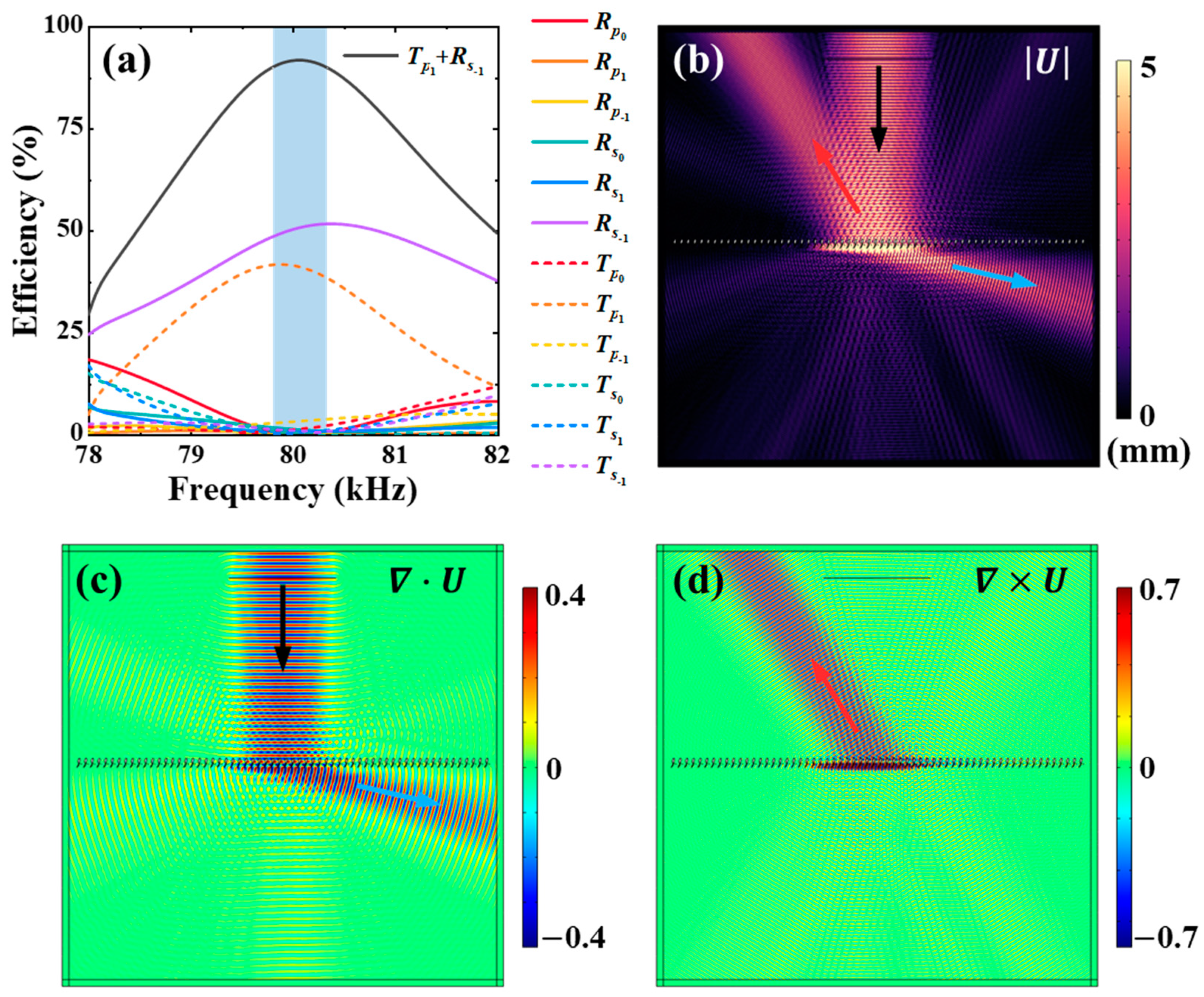
As a first example, in Figure 2 we demonstrate the high-efficiency anomalous diffraction effect along the R p 1 and T s 1 channels. After applying the GA, we can achieve high reflection efficiency along R p 1 channel and high transmission efficiency along T s 1 channel, with R p 1 = 46.1% and T s 1 = 49.0% at the operation frequency f 0 = 80 kHz. The optimized geometrical parameters are a 1 = 1.4166 cm, b 1 = 0.4566 cm, φ 1 = 0.112°, C 1 = (4.9571, 0) cm, a 2 = 1.4781 cm, b 2 = 0.4380 cm, φ 2 = 151.83°, C 2 = (2.228, 2.9195) cm, r = 0.4701 cm, and C 3 = (3.19, 5.1713) cm, respectively. The diffraction spectra are shown in Figure 2a, where the blue shaded region, f  [79.38, 80.60] kHz, corresponds to the frequency range with R p 1 + T s 1 > 90%. The magnitude of the displacement vector at f 0 is shown in Figure 2b, where black, blue, and red arrows denote the incident, reflected, and transmitted wave beams, respectively. We also plot the divergence and curl of the displacement field in Figure 2c,d, which corresponds to the longitudinal and transverse wave components, respectively. Thus, we clearly demonstrate that an exclusive and high-efficiency diffraction along the R p 1 and T s 1 channels can be realized with the smartly designed metagrating.
For the full-wave numerical simulations, we use the solid mechanics (frequency domain) module in COMSOL Multiphysics. The diffraction efficiency spectra shown in Figure 2a, for example, are calculated with a mesh resolution of λ p /50 with periodic boundary conditions (PBCs) applied at the left and right boundaries of the unit-cell (as marked by green lines in the inset of Figure 1). Furthermore, perfect matching layers (PMLs) are used at the upper and lower boundaries to absorb outgoing waves.
The displacement field distributions plotted in Figure 2b–d are obtained by using a grating structure with 62 unit-cells along the x-direction with a similar mesh resolution of finite elements, where a longitudinal plane wave is normally incident on the grating. For this case, PMLs are applied on the left, right, upper, and lower boundaries of the simulation domain.
In Table 1 we have summarized the diffraction efficiencies of a total of 12 channels calculated with different sizes of mesh (such as λ p /40, λ p /50, and λ p /100), we can observe that for a mesh size of λ p /50, the simulation results have already converged and are accurate.
Here we note that as a general design principle of the metagrating, one must ensure that the design degrees of freedoms (DOFs) of the unit-cell (i.e., the size, orientation, and position of elliptical cylinders) is equal to or larger than the number of tunable diffraction channels to be controlled [55]. Taking Figure 2 as an example, we need to simultaneously control 6 longitudinal wave channels ( R p 0 , R p 1 , R p 1 , T p 0 , T p 1 , and T p 1 ) and 6 transverse wave channels ( R s 0 , R s 1 , R s 1 , T s 0 , T s 1 , and T s 1 ), so that the diffracted wave can be driven into specific directions only. To this end, we must have enough design DOFs to achieve the desired wave-manipulation effect. It turns out that if each unit-cell contains two elliptical and one circular cylinder, we will have 12 independent geometrical parameters ( a 1 , a 2 , b 1 , b 2 , r, φ 1 , φ 2 , x 1 , x 2 , x 3 , y 2 , and y 3 ) so that the design DOFs (i.e., 12) are equal to the number (12) of tunable diffraction channels. Thus, we can achieve nearly perfect diffraction efficiencies along the desired deflection directions, as clearly shown in Figure 2.
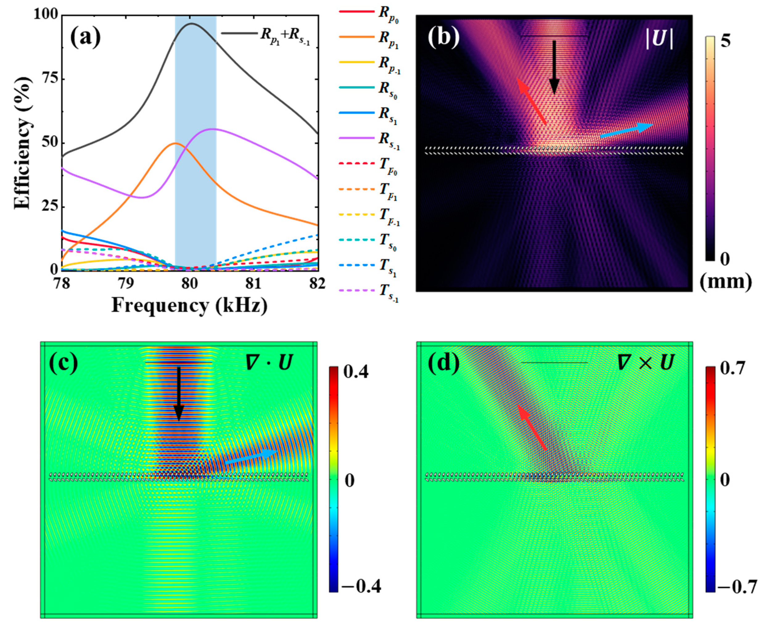
Of course, we can utilize a metagrating structure with three (or more) elliptical cylinders in each unit-cell, where 14 independent geometrical parameters ( a 1 , a 2 , a 3 , b 1 , b 2 , b 3 , φ 1 , φ 2 , φ 3 , x 1 , x 2 , x 3 , y 2 , and y 3 ) can provide us with more design DOFs than the number (12) of tunable diffraction channels. However, this does not comply with our design principle: we want to manipulate the diffracted waves with the simplest possible structure. Therefore, the unit-cell configuration of two elliptical and one circular cylinder is just enough for us. In short, a simpler unit-cell configuration cannot provide enough design DOFs, while a more complicated configuration is not necessarily needed. Therefore, the advantage of the current design is that we use the simplest possible grating structure to control as many as possible diffraction channels. Figure 2 shows that only longitudinal wave is reflected and that only a transverse wave is transmitted for a normally incident p-wave. In Figure 3 we will show a complementary scenario where only the transverse wave is reflected and only the longitudinal wave is transmitted for the same incident p-wave. In this case, we require that high-efficiency diffraction along the R s 1 and T p 1 channels are accomplished at the working frequency f 0 . By utilizing the GA, we can obtain high diffraction efficiencies of T p 1 = 41.4% and R s 1 = 50.3% along the desired channels, with corresponding optimized geometric parameters being a 1 = 2.9816 cm, b 1 = 0.3346 cm, φ 1 = 61.20°, C 1 = (3.0216, 0) cm, a 2 = 2.756 cm, b 2 = 0.9872 cm, φ 2 = 76.87°, C 2 = (3.8683, 5.3777) cm, r = 0.2611 cm, and C 3 = (6.5949, 1.4872) cm. The diffraction efficiency spectra for all 12 channels are shown in Figure 3a, where we observe that the total diffraction efficiency along the desired transmission and reflection directions satisfies T p 1 + R s 1 > 90% in the frequency range f  [79.80, 80.33] kHz. We also plot the magnitude of the displacement at f 0 in Figure 3b, along with the divergence and curl of the displacement field shown in Figure 3c,d. They unambiguously verify the exclusive and high-efficiency diffraction behaviors of elastic waves along the R s 1 and T p 1 channels.
In the above two examples, high-efficiency diffraction along one reflected channel and one transmitted channel is demonstrated. In the following paragraphs, we will show that the diffraction can be engineered so that only reflected channels or only transmitted channels are permitted. In Figure 4, for example, we require that all transmitted channels are suppressed and only reflection along the desired channels is allowed. By using the GA, we can steer the reflected wave only along R p 1 and R s 1 channels, with high diffraction efficiencies R p 1 = 46.4% and R s 1 = 50.2%, respectively. The corresponding geometric parameters are a 1 = 4.0418 cm, b 1 = 1.2327 cm, φ 1 = 143.88°, C 1 = (3.5065, 0) cm, a 2 = 3.2945 cm, b 2 = 1.4135 cm, φ 2 = 58.83°, C 2 = (3.1973, 9.9498) cm, r = 0.7053 cm, and C 3 = (3.4023, 6.4385) cm. Figure 4a shows the diffraction efficiency spectra for all 12 channels, where a high reflection efficiency ( R p 1 + R s 1 > 90%) is sustained within the frequency range f  [79.76, 80.39] kHz. We also plot the magnitude of the displacement at the operating frequency f 0 = 80 kHz in Figure 4b, along with the divergence and curl of the displacement in Figure 4c,d. Exclusive reflection along the R p 1 and R s 1 channels are observed.
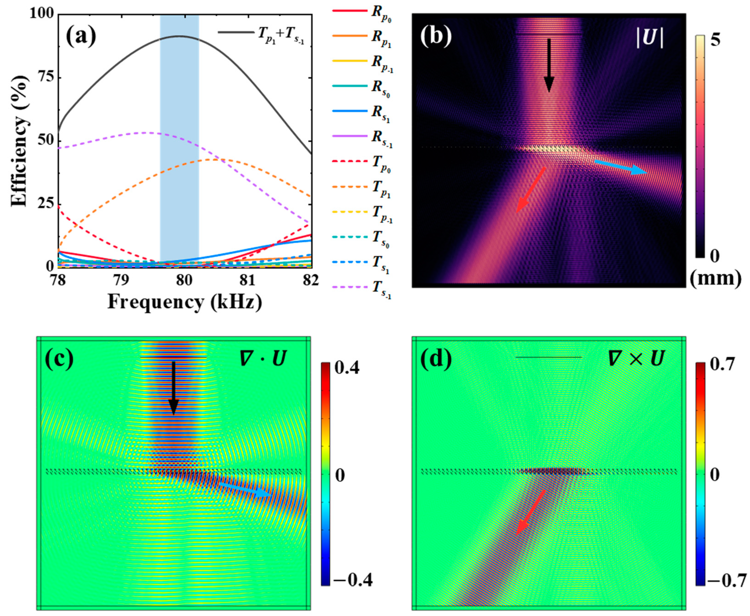
In contrast to Figure 4, we can also require that all reflection channels are closed while only transmission along the desired channels is permitted. As shown in Figure 5, transmissions along T p 1 and T s 1 channels are the only allowed diffraction channels. By using the intelligent optimization method, we obtain a metagrating design with high transmission efficiency as T p 1 = 40.8 % and T s 1 = 50.4 % , where the corresponding geometric parameters are a 1 = 2.6851 cm, b 1 = 0.13 cm, φ 1 = 127.19°, C 1 = (3.8685, 0) cm, a 2 = 1.5396 cm, b 2 = 0.5797 cm, φ 2 = 125.43°, C 2 = (3.6288, 6.5671) cm, r = 0.3518 cm, and C 3 = (6.1036, 3.0839) cm. We show the diffraction efficiency spectra in Figure 5a, where the blue shaded area represents the frequency range f  [79.60, 80.22] kHz over which T p 1 + T s 1 > 90%. Figure 5b–d shows the magnitude of the displacement, and the longitudinal and transverse wave components, respectively, at the operating frequency f 0 , which undoubtedly verifies the desired anomalous transmission phenomenon.
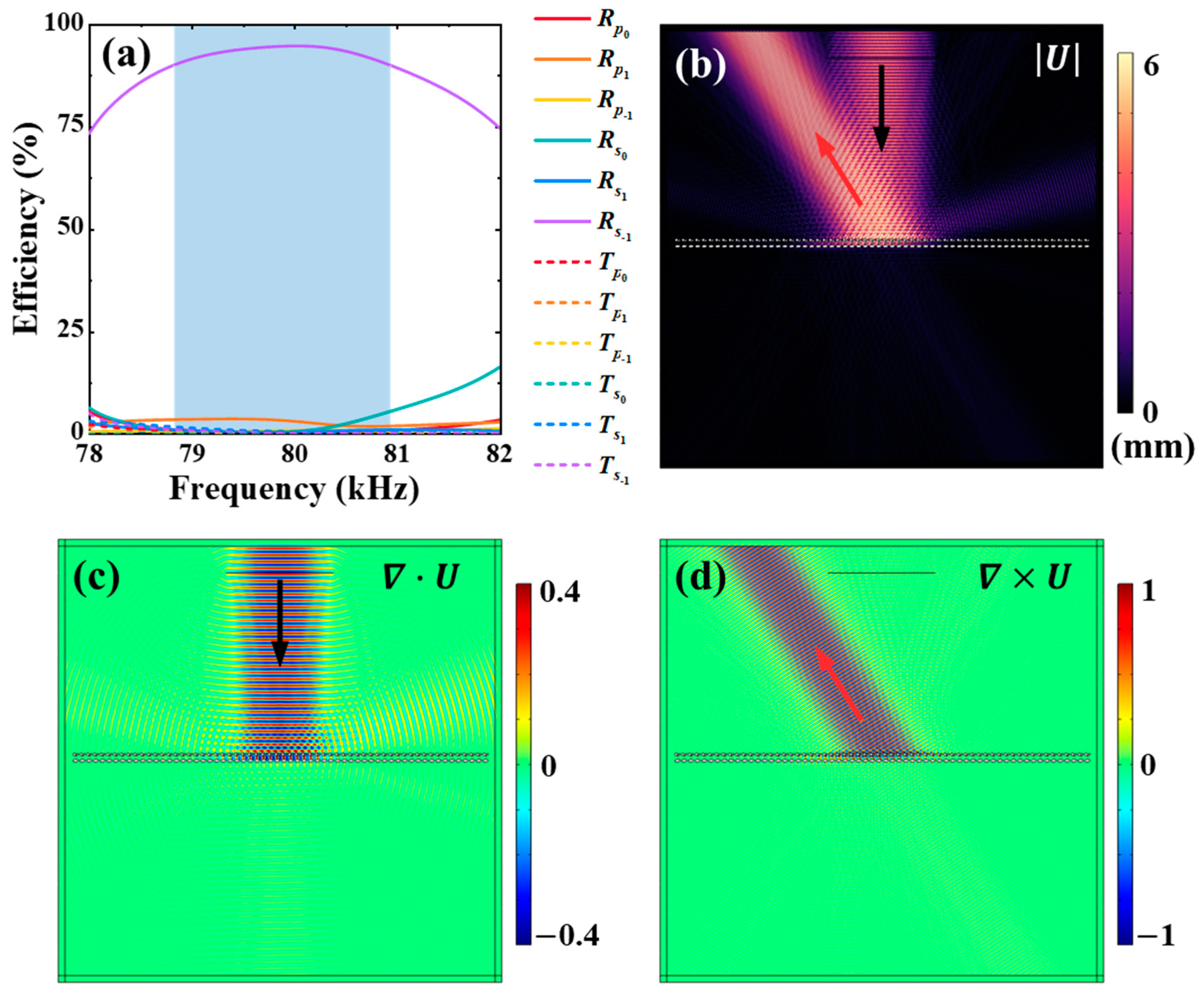
Next, we will demonstrate that the elastic metagrating can be used to realize high-efficiency mode conversion, e.g., transforming an incident p-wave completely and exclusively into a reflected s-wave along the desired channel. An example is shown in Figure 6, where the only allowed diffraction channel is the R s 1 channel, when a p-wave is normally incident on the grating. By utilizing the GA, we obtain a high reflection efficiency along the desired channel, i.e., R s 1 = 94.7%, with the corresponding structural parameters given by a 1 = 2.9411 cm, b 1 = 1.4895 cm, φ 1 = 5.36°, C 1 = (4.4315, 0) cm, a 2 = 1.9343 cm, b 2 = 0.7616 cm, φ 2 = 41.42°, C 2 = (5.9854, 6.5335) cm, r = 1.5502 cm, and C 3 = (3.1516, 7.1231) cm. From the diffraction efficiency spectra plotted in Figure 6a, we see that R s 1 > 90% within the frequency range f  [78.83, 80.93] kHz, as marked by the blue shaded region. Figure 6b–d show the magnitude of the displacement, the divergence, and the curl of the displacement at f 0 = 80 kHz, confirming the almost unitary efficiency of mode conversion.

4. Conclusions

In this article, we propose an intelligent design paradigm for elastic metagratings which can simultaneously modulate the reflection and transmission of both longitudinal and transverse waves. Although the metagrating is simply structured and consists only of a one-dimensional array of hollow cylinders carved in a steel background, it enables the complex functionality of individual and separate control over every reflection and transmission channel. By use of elastic wave diffraction theory and intelligent optimization algorithms, both reflected and transmitted waves can be driven into the desired direction with almost perfect efficiency. Various wave-front manipulation effects such as anomalous transmission and pure mode conversion are demonstrated through full-wave numerical simulations. These attractive functionalities and associated smart design approaches are expected to be useful in application scenarios such as non-destructive structural monitoring and smart planar devices.

Author Contributions

Conceptualization, J.M. and L.F.; methodology, J.M.; software, L.F.; formal analysis, J.M. and L.F.; investigation, J.M., L.F. and X.H.; resources, J.M. and X.H.; writing—original draft preparation, J.M. and L.F.; writing—review and editing, J.M., L.F. and X.H.; supervision, J.M. and X.H.; funding acquisition, J.M. and X.H. All authors have read and agreed to the published version of the manuscript.

Funding

This research was funded by Guangdong Basic and Applied Basic Research Foundation under Grant No. 2021A1515010322 and Guangdong Province Key Research & Development Program under Grant No. 2020B0404010001.

Institutional Review Board Statement

Not applicable.

Informed Consent Statement

Not applicable.

Data Availability Statement

Not applicable.

Conflicts of Interest

The authors declare no conflict of interest. The funders had no role in the design of the study; in the collection, analyses, or interpretation of data; in the writing of the manuscript, or in the decision to publish the results.

References

  1. Yu, N.; Genevet, P.; Kats, M.A.; Aieta, F.; Tetienne, J.; Capasso, F.; Gaburro, Z. Light propagation with phase discontinuities: Generalized laws of reflection and refraction. Science 2011, 334, 333–337. [Google Scholar] [CrossRef] [PubMed] [Green Version]
  2. Assouar, B.; Liang, B.; Wu, Y.; Li, Y.; Cheng, J.C.; Jing, Y. Acoustic metasurfaces. Nat. Rev. Mater. 2018, 3, 460–472. [Google Scholar] [CrossRef] [Green Version]
  3. Mei, J.; Wu, Y. Controllable transmission and total reflection through an impedance-matched acoustic metasurface. New J. Phys. 2014, 16, 123007. [Google Scholar] [CrossRef]
  4. Cheng, Y.; Zhou, C.; Yuan, B.G.; Wu, D.J.; Wei, Q.; Liu, X.J. Ultra-sparse metasurface for high reflection of low-frequency sound based on artificial Mie resonances. Nat. Mater. 2015, 14, 1013–1019. [Google Scholar] [CrossRef]
  5. Tang, K.; Qiu, C.; Ke, M.; Lu, J.; Ye, Y.; Liu, Z. Anomalous refraction of airborne sound through ultrathin metasurfaces. Sci. Rep. 2014, 4, 6517. [Google Scholar] [CrossRef] [Green Version]
  6. Tang, K.; Qiu, C.; Lu, J.; Ke, M.; Liu, Z. Focusing and directional beaming effects of airborne sound through a planar lens with zigzag slits. J. Appl. Phys. 2015, 117, 024503. [Google Scholar] [CrossRef] [Green Version]
  7. Díaz-Rubio, A.; Tretyakov, S.A. Acoustic metasurfaces for scattering-free anomalous reflection and refraction. Phys. Rev. B 2017, 96, 125409. [Google Scholar] [CrossRef] [Green Version]
  8. Li, J.; Shen, C.; Díaz-Rubio, A.; Tretyakov, S.A.; Cummer, S.A. Systematic design and experimental demonstration of bianisotropic metasurfaces for scattering-free manipulation of acoustic wavefronts. Nat. Commun. 2018, 9, 1342. [Google Scholar] [CrossRef]
  9. Guo, X.; Gusev, V.E.; Bertoldi, K.; Tournat, V. Manipulating acoustic wave reflection by a nonlinear elastic metasurface. J. Appl. Phys. 2018, 123, 124901. [Google Scholar] [CrossRef]
  10. Zhou, H.T.; Fu, W.X.; Wang, Y.F.; Wang, Y.S. High-efficiency Ultrathin Nonlocal Waterborne Acoustic Metasurface. Phy. Rev. Appl. 2021, 15, 044046. [Google Scholar] [CrossRef]
  11. Zhou, H.T.; Fu, W.X.; Li, X.S.; Wang, Y.F.; Wang, Y.S. Loosely coupled reflective impedance metasurfaces: Precise manipulation of waterborne sound by topology optimization. Mech. Syst. Signal. Process. 2022, 177, 109228. [Google Scholar] [CrossRef]
  12. Danila, O.; Manaila-Maximean, D. Bifunctional metamaterials using spatial phase gradient architectures: Generalized reflection and refraction considerations. Materials 2021, 14, 2201. [Google Scholar] [CrossRef] [PubMed]
  13. Danila, O. Polyvinylidene fluoride-based metasurface for high-quality active switching and spectrum shaping in the terahertz g-band. Polymers 2021, 13, 1860. [Google Scholar] [CrossRef] [PubMed]
  14. Esfahlani, H.; Karkar, S.; Lissek, H.; Mosig, J.R. Acoustic carpet cloak based on an ultrathin metasurface. Phys. Rev. B 2016, 94, 014302. [Google Scholar] [CrossRef] [Green Version]
  15. Qi, S.; Li, Y.; Assouar, B. Acoustic focusing and energy confinement based on multilateral metasurfaces. Phys. Rev. Appl. 2017, 7, 054006. [Google Scholar] [CrossRef]
  16. Xie, H.; Hou, Z. Nonlocal Metasurface for Acoustic Focusing. Phys. Rev. Appl. 2021, 15, 034054. [Google Scholar] [CrossRef]
  17. Kildishev, A.V.; Boltasseva, A.; Shalaev, V.M. Planar photonics with metasurfaces. Science 2013, 339, 1232009. [Google Scholar] [CrossRef] [Green Version]
  18. Ra’Di, Y.; Sounas, D.L.; Alù, A. Metagratings: Beyond the Limits of Graded Metasurfaces for Wave Front Control. Phys. Rev. Lett. 2017, 119, 067404. [Google Scholar] [CrossRef]
  19. Epstein, A.; Rabinovich, O. Unveiling the Properties of Metagratings via a Detailed Analytical Model for Synthesis and Analysis. Phys. Rev. Appl. 2017, 8, 054037. [Google Scholar] [CrossRef] [Green Version]
  20. Torrent, D. Acoustic anomalous reflectors based on diffraction grating engineering. Phys. Rev. B 2018, 98, 060101. [Google Scholar] [CrossRef] [Green Version]
  21. Hou, Z.; Fang, X.; Li, Y.; Assouar, B. Highly Efficient Acoustic Metagrating with Strongly Coupled Surface Grooves. Phys. Rev. Appl. 2019, 12, 034021. [Google Scholar] [CrossRef] [Green Version]
  22. Fu, Y.; Shen, C.; Cao, Y.; Gao, L.; Chen, H.; Chan, C.T.; Cummer, S.A.; Xu, Y. Reversal of transmission and reflection based on acoustic metagratings with integer parity design. Nat. Commun. 2019, 10, 2326. [Google Scholar] [CrossRef] [PubMed]
  23. Fan, L.; Mei, J. Metagratings for Waterborne Sound: Various Functionalities Enabled by an Efficient Inverse Design Approach. Phys. Rev. Appl. 2020, 14, 044003. [Google Scholar] [CrossRef]
  24. Chiang, Y.K.; Oberst, S.; Melnikov, A.; Quan, L.; Marburg, S.; Alù, A.; Powell, D.A. Reconfigurable Acoustic Metagrating for High-Efficiency Anomalous Reflection. Phys. Rev. Appl. 2020, 13, 064067. [Google Scholar] [CrossRef]
  25. Wang, Y.; Cheng, Y.; Liu, X. Modulation of acoustic waves by a broadband metagrating. Sci. Rep. 2019, 9, 7271. [Google Scholar] [CrossRef]
  26. Ni, H.; Fang, X.; Hou, Z.; Li, Y.; Assouar, B. High-efficiency anomalous splitter by acoustic meta-grating. Phys. Rev. B 2019, 100, 104104. [Google Scholar] [CrossRef] [Green Version]
  27. Fan, L.; Mei, J. Acoustic Metagrating Circulators: Nonreciprocal, Robust, and Tunable Manipulation with Unitary Efficiency. Phys. Rev. Appl. 2021, 15, 064002. [Google Scholar] [CrossRef]
  28. Fan, L.; Mei, J. Multifunctional Waterborne Acoustic Metagratings: From Extraordinary Transmission to Total and Abnormal Reflection. Phys. Rev. Appl. 2021, 16, 044029. [Google Scholar] [CrossRef]
  29. He, J.; Jiang, X.; Ta, D.; Wang, W. Experimental demonstration of underwater ultrasound cloaking based on metagrating. Appl. Phys. Lett. 2020, 117, 091901. [Google Scholar] [CrossRef]
  30. Zhao, D.; Ye, Y.; Xu, S.; Zhu, X.; Yi, L. Broadband and wide-angle negative reflection at a phononic crystal boundary. Appl. Phys. Lett. 2014, 104, 043503. [Google Scholar]
  31. Yang, Y.; Jia, H.; Bi, Y.; Zhao, H.; Yang, J. Experimental demonstration of an acoustic asymmetric diffraction grating based on passive parity-time-symmetric medium. Phys. Rev. Appl. 2019, 12, 034040. [Google Scholar] [CrossRef] [Green Version]
  32. Yang, Y.; Jia, H.; Wang, S.; Zhang, P.; Yang, J. Diffraction control in a non-Hermitian acoustic grating. Appl. Phys. Lett. 2020, 116, 213501. [Google Scholar] [CrossRef]
  33. Kim, S.Y.; Lee, W.; Lee, J.S.; Kim, Y.Y. Longitudinal wave steering using beam-type elastic metagratings. Mech. Syst. Signal Process. 2021, 156, 107688. [Google Scholar] [CrossRef]
  34. Packo, P.; Norris, A.N.; Torrent, D. Inverse grating problem: Efficient design of anomalous flexural wave reflectors and refractors. Phys. Rev. Appl. 2019, 11, 014023. [Google Scholar] [CrossRef] [Green Version]
  35. Zhu, H.; Semperlotti, F. Anomalous refraction of acoustic guided waves in solids with geometrically tapered metasurfaces. Phys. Rev. Lett. 2016, 117, 034302. [Google Scholar] [CrossRef] [PubMed] [Green Version]
  36. Liu, Y.; Liang, Z.; Liu, F.; Diba, O.; Lamb, A.; Li, J. Source illusion devices for flexural lamb waves using elastic metasurfaces. Phys. Rev. Lett. 2017, 119, 034301. [Google Scholar] [CrossRef]
  37. Chen, Y.; Li, X.; Nassar, H.; Hu, G.; Huang, G. A programmable metasurface for real time control of broadband elastic rays. Smart Mater. Struct. 2018, 27, 115011. [Google Scholar] [CrossRef] [Green Version]
  38. Cao, L.; Xu, Y.; Assouar, B.; Yang, Z. Asymmetric flexural wave transmission based on dual-layer elastic gradient metasurfaces. Appl. Phys. Lett. 2018, 113, 183506. [Google Scholar] [CrossRef]
  39. Cao, L.; Yang, Z.; Xu, Y.; Fan, S.W.; Zhu, Y.; Chen, Z.; Vincent, B.; Assouar, B. Disordered elastic metasurfaces. Phys. Rev. Appl. 2020, 13, 014054. [Google Scholar] [CrossRef]
  40. Kim, M.S.; Lee, W.; Park, C.I.; Oh, J.H. Elastic wave energy entrapment for reflectionless metasurface. Phys. Rev. Appl. 2020, 13, 054036. [Google Scholar] [CrossRef]
  41. Chaplain, G.J.; De Ponti, J.M.; Aguzzi, G.; Colombi, A.; Craster, R.V. Topological rainbow trapping for elastic energy harvesting in graded Su-Schrieffer-Heeger systems. Phys. Rev. Appl. 2020, 14, 054035. [Google Scholar] [CrossRef]
  42. Yuan, S.M.; Chen, A.L.; Cao, L.; Zhang, H.W.; Fan, S.W.; Assouar, B.; Wang, Y.S. Tunable multifunctional fish-bone elastic metasurface for the wavefront manipulation of the transmitted in-plane waves. J. Appl. Phys. 2020, 128, 224502. [Google Scholar] [CrossRef]
  43. Ruan, Y.; Liang, X.; Hu, C. Retroreflection of flexural wave by using elastic metasurface. J. Appl. Phys. 2020, 128, 045116. [Google Scholar] [CrossRef]
  44. Li, B.; Hu, Y.; Chen, J.; Su, G.; Liu, Y.; Zhao, M.; Li, Z. Efficient asymmetric transmission of elastic waves in thin plates with lossless metasurfaces. Phys. Rev. Appl. 2020, 14, 054029. [Google Scholar] [CrossRef]
  45. Zheng, M.; Park, C.I.; Liu, X.; Zhu, R.; Hu, G.; Kim, Y.Y. Non-resonant metasurface for broadband elastic wave mode splitting. Appl. Phys. Lett. 2020, 116, 171903. [Google Scholar] [CrossRef]
  46. Rong, J.; Ye, W.; Zhang, S.; Liu, Y. Frequency-coded passive multifunctional elastic metasurfaces. Adv. Funct. Mater. 2020, 30, 2005285. [Google Scholar] [CrossRef]
  47. Li, X.; Chen, Y.; Zhu, R.; Huang, G. An active meta-layer for optimal flexural wave absorption and cloaking. Mech. Syst. Signal Process. 2021, 149, 107324. [Google Scholar] [CrossRef]
  48. Jin, Y.; Wang, W.; Khelif, A.; Djafari-Rouhani, B. Elastic metasurfaces for deep and robust subwavelength focusing and imaging. Phys. Rev. Appl. 2021, 15, 024005. [Google Scholar] [CrossRef]
  49. Lin, Z.; Tol, S. Elastic metasurfaces for full wavefront control and low-frequency energy harvesting. J. Vib. Acoust. 2021, 143, 061005. [Google Scholar]
  50. Li, X.S.; Wang, Y.F.; Wang, Y.S. Sparse binary metasurfaces for steering the flexural waves. Extreme Mech. Lett. 2022, 52, 101675. [Google Scholar]
  51. Su, X.; Lu, Z.; Norris, A.N. Elastic metasurfaces for splitting SV- and P-waves in elastic solids. J. Appl. Phys. 2018, 123, 091701. [Google Scholar] [CrossRef] [Green Version]
  52. Zhang, J.; Su, X.; Pennec, Y.; Jing, Y.; Liu, X.; Hu, N. Wavefront steering of elastic shear vertical waves in solids via a composite-plate-based metasurface. J. Appl. Phys. 2018, 124, 164505. [Google Scholar] [CrossRef] [Green Version]
  53. Ahn, B.; Lee, H.; Lee, J.S.; Kim, Y.Y. Topology optimization of metasurfaces for anomalous reflection of longitudinal elastic waves. Comput. Methods Appl. Mech. Eng. 2019, 357, 112582. [Google Scholar] [CrossRef]
  54. Rong, J.; Ye, W. Multifunctional elastic metasurface design with topology optimization. Acta Mater. 2020, 185, 382–399. [Google Scholar] [CrossRef]
  55. Spägele, C.; Tamagnone, M.; Kazakov, D.; Ossiander, M.; Piccardo, M.; Capasso, F. Multifunctional wide-angle optics and lasing based on supercell metasurfaces. Nat. Commun. 2021, 12, 3787. [Google Scholar] [CrossRef] [PubMed]
Figure 1. Physical configuration of the elastic metagratings, where six longitudinal (blue arrows) and six transverse (red arrows) diffraction channels are schematically shown. Each unit-cell consists of two elliptical and one circular hollow cylinders curved in a steel background, as shown in the inset with corresponding geometrical parameters marked.
Crystals 12 00901 g001
Figure 2. High-efficiency diffraction along the R p 1 and T s 1 channels when a p-wave is normally incident on the metagrating. (a) The diffraction efficiency spectra for all 12 channels, where f 0 = 80 kHz is the operating frequency; (b) shows the amplitude of displacement amplitude at f 0 ; (c,d) show the divergence and curl of the displacement field, corresponding to longitudinal and transverse wave components, respectively. Black, blue, and red arrows represent the incident p-wave, reflected p-wave, and transmitted s-wave, respectively.
Crystals 12 00901 g002
Figure 3. High-efficiency diffraction along the T p 1 and R s 1 channels when a p-wave is normally incident on the metagrating. (a) The diffraction efficiency spectra for all 12 channels, where f 0 = 80 kHz is the operating frequency; (b) shows the amplitude of displacement amplitude at f 0 ; (c,d) show the divergence and curl of the displacement field, corresponding to longitudinal and transverse wave components, respectively. Black, blue, and red arrows represent the incident p-wave, transmitted p-wave, and reflected s-wave, respectively.
Crystals 12 00901 g003
Figure 4. High-efficiency reflection along the R p 1 and R s 1 channels when a p-wave is normally incident on the metagrating. (a) The diffraction efficiency spectra for all 12 channels, where f 0 = 80 kHz is the operating frequency; (b) shows the amplitude of displacement amplitude at f 0 ; (c,d) show the divergence and curl of the displacement field, corresponding to longitudinal and transverse wave components, respectively. Black, blue and red arrows represent the incident p-wave, reflected p-wave, and reflected s-wave, respectively.
Crystals 12 00901 g004
Figure 5. High-efficiency transmission along the T p 1 and T s 1 channels when a p-wave is normally incident on the metagrating. (a) The diffraction efficiency spectra for all 12 channels, where f 0 = 80 kHz is the operating frequency; (b) shows the amplitude of displacement amplitude at f 0 ; (c,d) show the divergence and curl of the displacement field, corresponding to longitudinal and transverse wave components, respectively. Black, blue and red arrows represent the incident p-wave, transmitted p-wave, and transmitted s-wave, respectively.
Crystals 12 00901 g005
Figure 6. Mode conversion functionality of the metagrating, where a normally incident p-wave is completely and exclusively converted into a reflected s-wave along the R s 1 channel. (a) The diffraction efficiency spectra for all 12 channels, where f 0 = 80 kHz is the operating frequency; (b) shows the amplitude of displacement amplitude at f 0 ; (c,d) show the divergence and curl of the displacement field, corresponding to longitudinal and transverse wave components, respectively. Black and red arrows represent the incident p-wave and reflected s-wave, respectively.
Crystals 12 00901 g006
Table 1. Diffraction efficiency with different sizes of mesh (%).
Mesh Size λ p / 40 λ p / 50 λ p / 100
R p 0 1.261.221.22
R p 1 46.2446.0945.97
R p 1 0.820.900.83
R s 0 0.050.050.05
R s 1 0.610.570.59
R s 1 0.960.980.99
T p 0 0.010.010.01
T p 1 0.130.120.12
T p 1 0.510.540.58
T s 0 0.090.080.09
T s 1 0.440.450.45
T s 1 48.8848.9849.10
Publisher’s Note: MDPI stays neutral with regard to jurisdictional claims in published maps and institutional affiliations.