
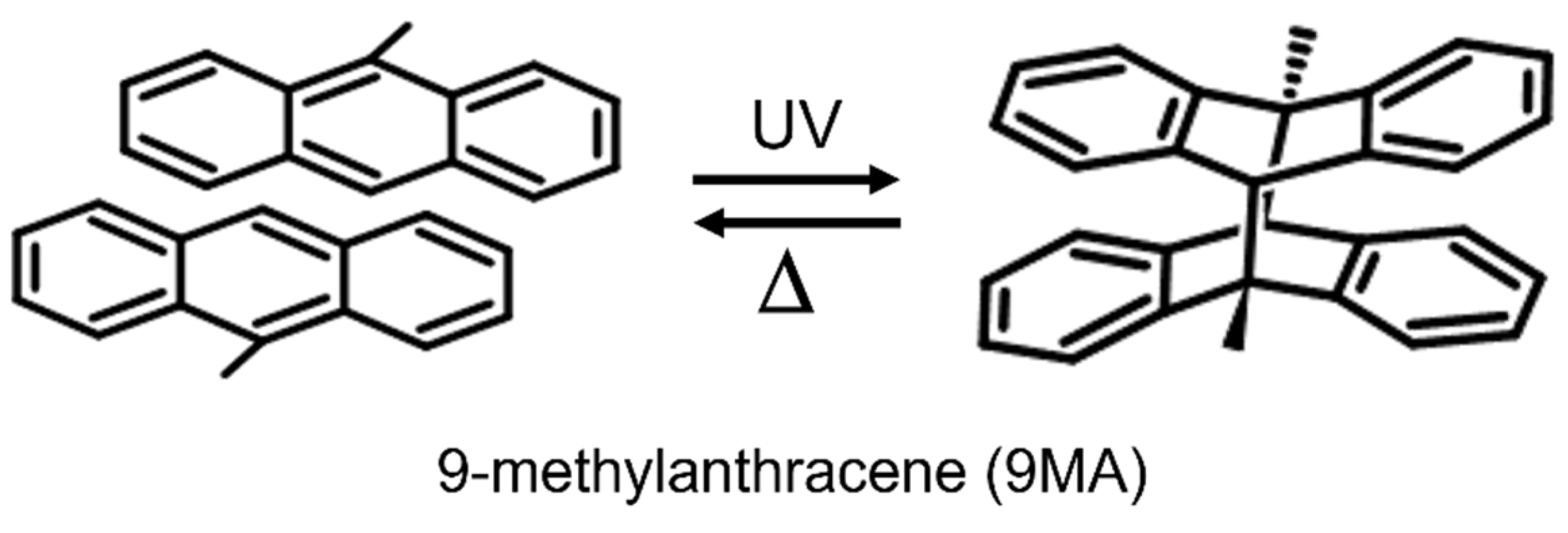
Photomechanical Structures Based on Porous Alumina Templates Filled with 9-Methylanthracene Nanowires

 ,
,  ,
,  , and
, and 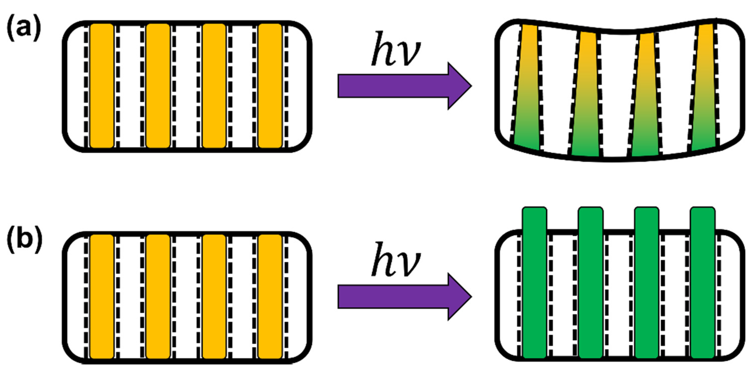
Abstract
:1. Introduction
2. Experimental
2.1. Sample Preparation
2.2. Characterization
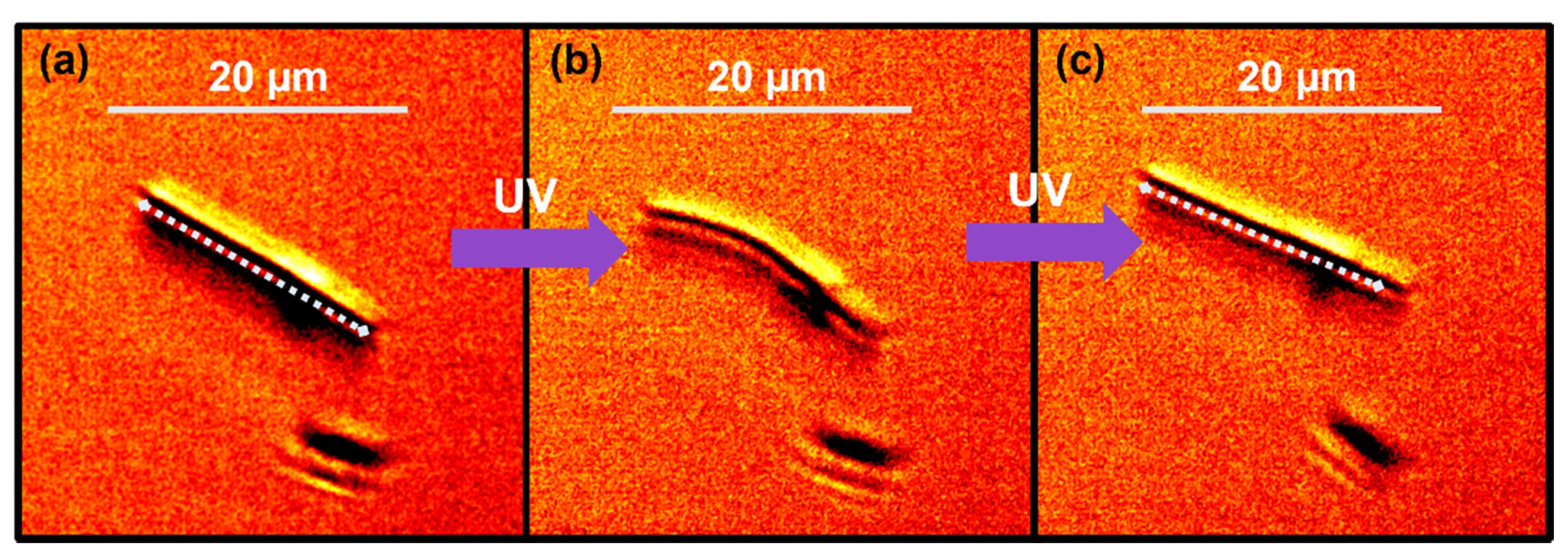
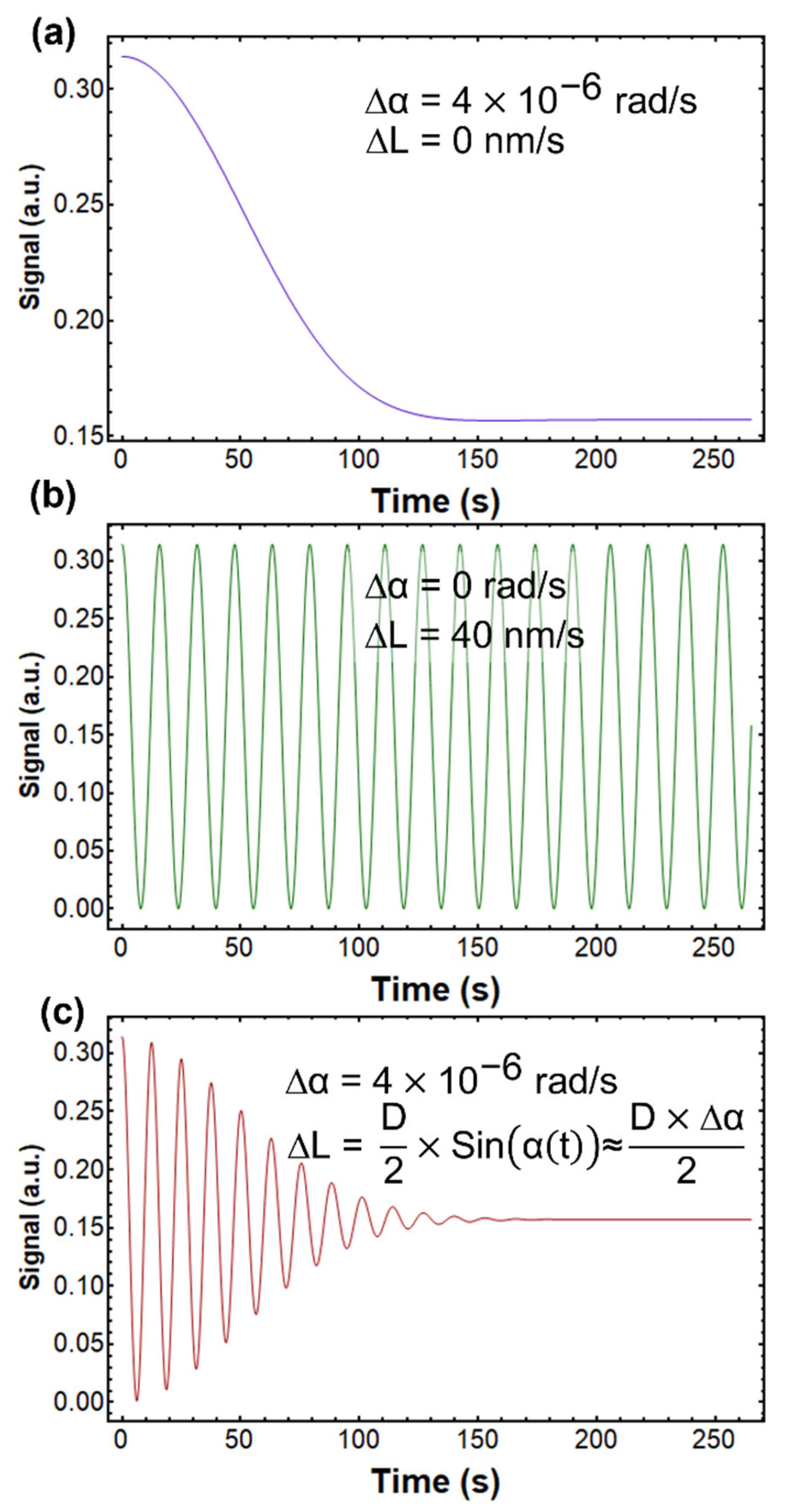
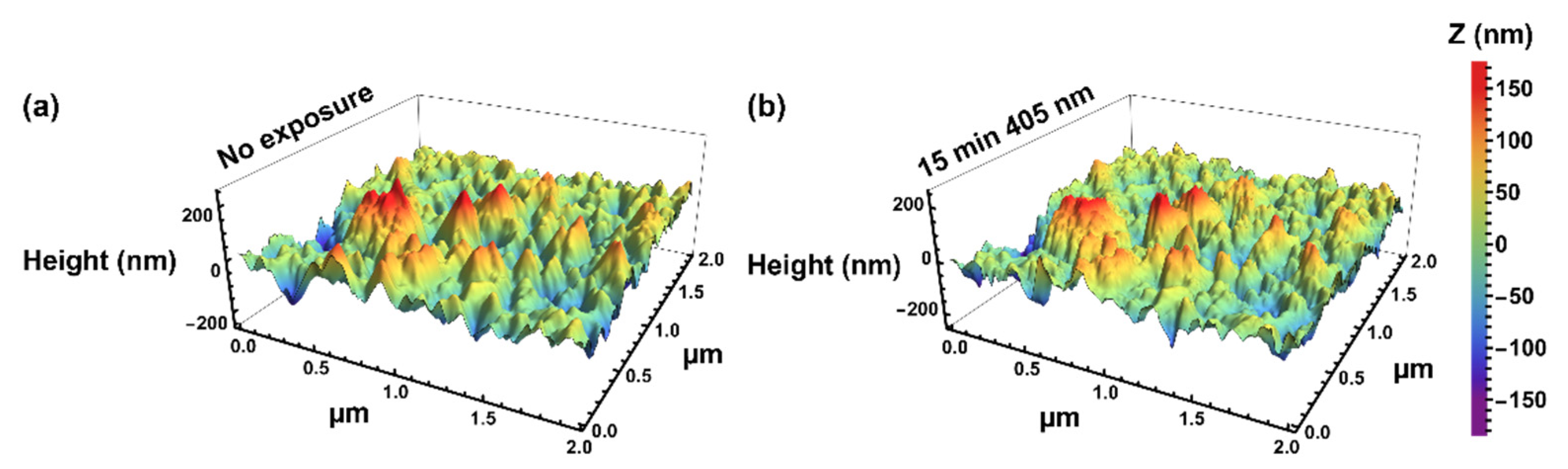
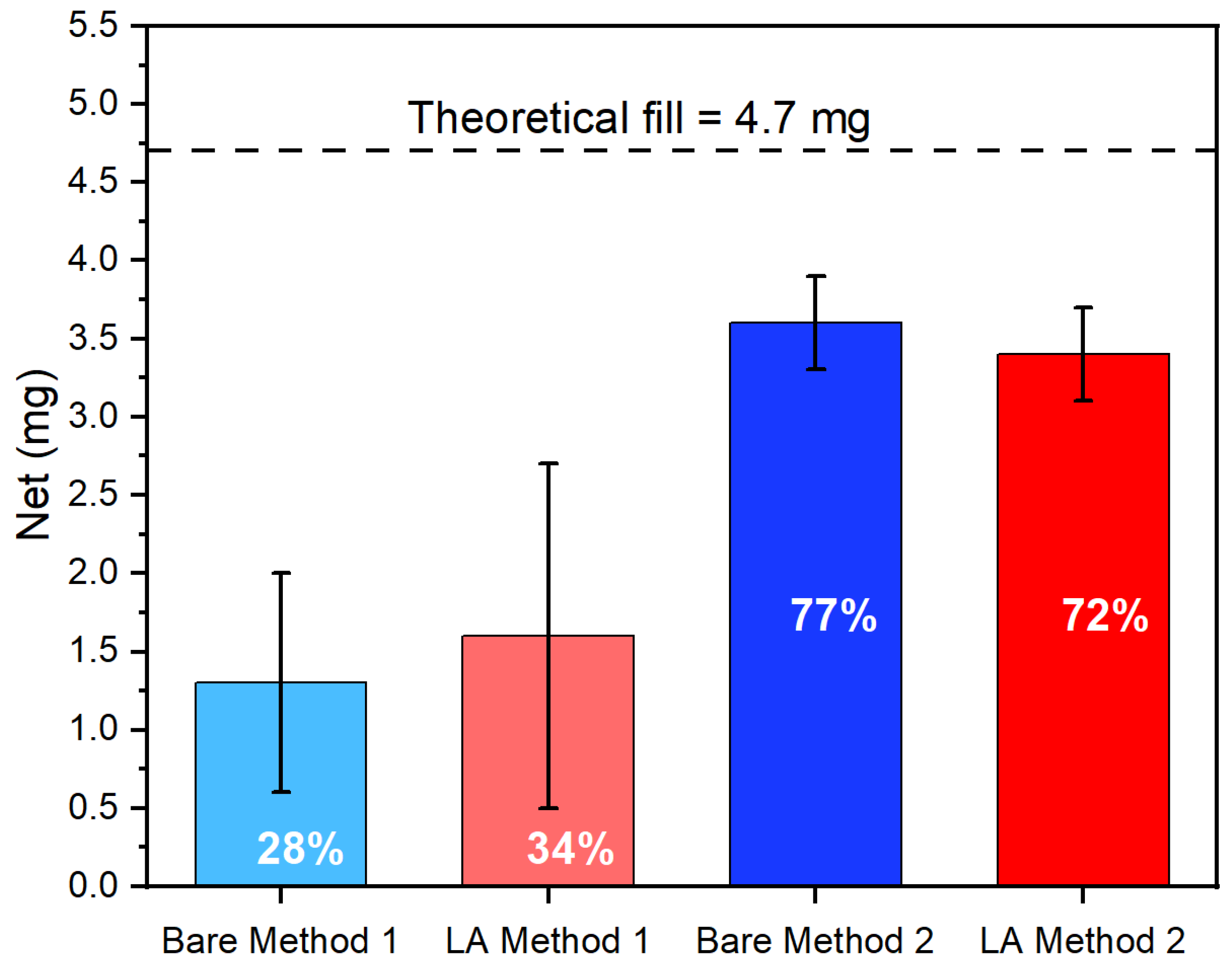
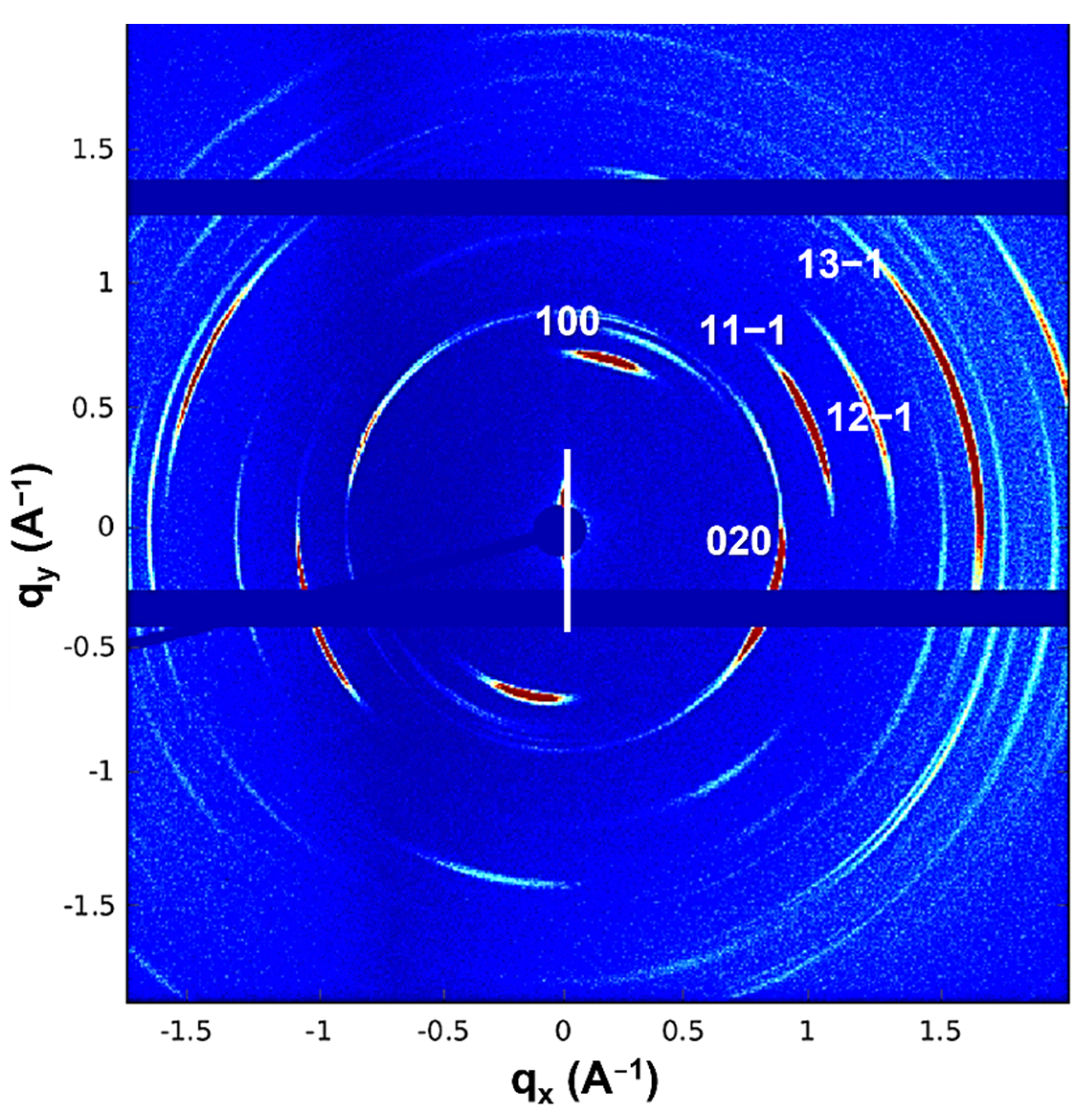
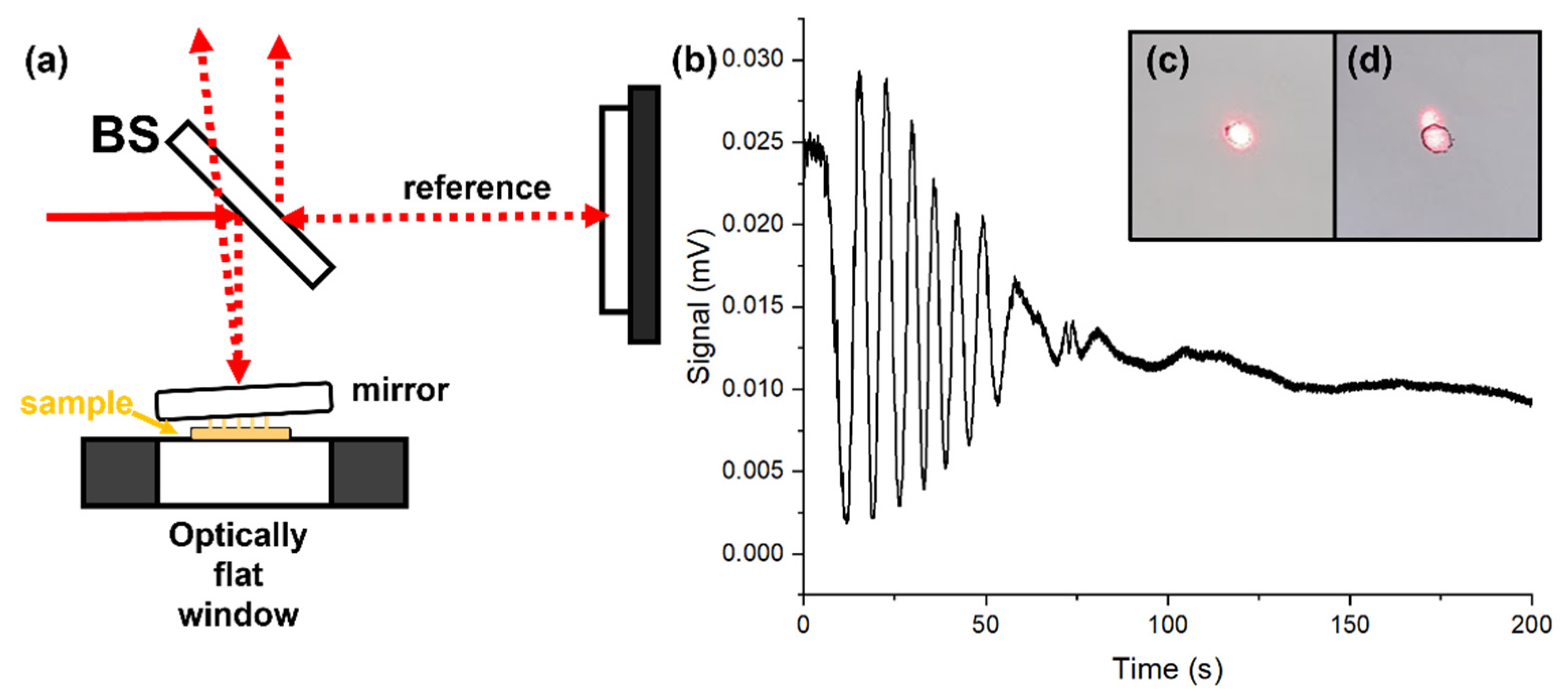
3. Results
4. Conclusions
Supplementary Materials
Author Contributions
Funding
Institutional Review Board Statement
Informed Consent Statement
Data Availability Statement
Conflicts of Interest
References
- White, T.J. Photomechanical Materials, Composites, and Systems, 1st ed.; Wiley: Hoboken, NJ, USA, 2017. [Google Scholar]
- Kuzyk, M.G.; Dawson, N.J. Photomechanical materials and applications: A tutorial. Adv. Opt. Photonics 2020, 12, 847–1011. [Google Scholar] [CrossRef]
- Taniguchi, T.; Asahi, T.; Koshima, H. Photomechanical Azobenzene Crystals. Crystals 2019, 9, 437. [Google Scholar] [CrossRef] [Green Version]
- Kim, T.; Zhu, L.; Al-Kaysi, R.O.; Bardeen, C.J. Organic photomechanical materials. ChemPhysChem 2014, 15, 400–414. [Google Scholar] [CrossRef] [PubMed]
- Ikeda, T.; Mamiya, J.; Yu, Y. Photomechanics of liquid-crystalline elastomers and other polymers. Angew. Chem. Int. Ed. 2007, 46, 506–528. [Google Scholar] [CrossRef]
- Al-Kaysi, R.O.; Muller, A.M.; Bardeen, C.J. Photochemically driven shape changes of crystalline organic nanorods. J. Am. Chem. Soc. 2006, 128, 15938–15939. [Google Scholar] [CrossRef]
- Kobatake, S.; Takami, S.; Muto, H.; Ishikawa, T.; Irie, M. Rapid and reversible shape changes of molecular crystals on photoirradiation. Nature 2007, 446, 778–781. [Google Scholar] [CrossRef]
- Koshima, H.; Ojima, N.; Uchimoto, H. Mechanical motion of azobenzene crystals upon photoirradiation. J. Am. Chem. Soc. 2009, 131, 6890–6891. [Google Scholar] [CrossRef]
- Morimoto, M.; Irie, M. A diarylethene cocrystal that converts light into mechanical work. J. Am. Chem. Soc. 2010, 132, 14172–14178. [Google Scholar] [CrossRef]
- Naumov, P.; Kowalik, J.; Solntsev, K.M.; Baldridge, A.; Moon, J.-S.; Kranz, C.; Tolbert, L.M. Topochemistry and Photomechanical Effects in Crystals of Green Fluorescent Protein-like Chromophores: Effects of Hydrogen Bonding and Crystal Packing. J. Am. Chem. Soc. 2010, 132, 5845–5857. [Google Scholar] [CrossRef]
- Bushuyev, O.S.; Tomberg, A.; Friscic, T.; Barrett, C.J. Shaping Crystals with Light: Crystal-to-Crystal Isomerization and Photomechanical Effect in Fluorinated Azobenzenes. J. Am. Chem. Soc. 2013, 135, 12556–12559. [Google Scholar] [CrossRef]
- Nath, N.K.; Pejov, L.; Nichols, S.M.; Hu, C.; Saleh, N.; Kahr, B.; Naumov, P. Model for Photoinduced Bending of Slender Molecular Crystals. J. Am. Chem. Soc. 2014, 136, 2757–2766. [Google Scholar] [CrossRef] [PubMed]
- Naumov, P.; Chizhik, S.; Panda, M.K.; Nath, N.K.; Boldyreva, E. Mechanically Responsive Molecular Crystals. Chem. Rev. 2015, 115, 12440–12490. [Google Scholar] [CrossRef] [PubMed]
- Wang, H.; Chen, P.; Wu, Z.; Zhao, J.; Sun, J.; Lu, R. Bending, Curling, Rolling, and Salient Behavior of Molecular Crystals Driven by [2+2] Cycloaddition of a Styrylbenzoxazole Derivative. Angew. Chem. Int. Ed. 2017, 56, 9463–9467. [Google Scholar] [CrossRef]
- Kitagawa, D.; Tsujioka, H.; Tong, F.; Dong, X.; Bardeen, C.J.; Kobatake, S. Control of Photomechanical Crystal Twisting by Illumination Direction. J. Am. Chem. Soc. 2018, 140, 4208–4212. [Google Scholar] [CrossRef]
- Spackman, P.R.; Grosjean, A.; Thomas, S.P.; Karothu, D.P.; Naumov, P.; Spackman, M.A. Quantifying Mechanical Properties of Molecular Crystals: A Critical Overview of Experimental Elastic Tensors. Angew. Chem. Int. Ed. 2021, 61, e202110716. [Google Scholar] [CrossRef]
- Takahashi, S.; Miura, H.; Kasai, H.; Okada, S.; Oikawa, H.; Nakanishi, H. Single-crystal-to-single-crystal transformation of diolefin derivatives in nanocrystals. J. Am. Chem. Soc. 2002, 124, 10944–10945. [Google Scholar] [CrossRef]
- Bucar, D.K.; MacGillivray, L.R. Preparation and reactivity of nanocrystalline cocrystals formed via sonocrystallization. J. Am. Chem. Soc. 2007, 129, 32–33. [Google Scholar] [CrossRef]
- Li, W.; Tierce, N.T.; Bekyarova, E.; Bardeen, C.J. Protection of Molecular Microcrystals by Encapsulation under Single-Layer Graphene. ACS Omega 2018, 3, 8129–8134. [Google Scholar] [CrossRef]
- Xu, P.; Yu, Q.; Chen, Y.; Cheng, P.; Zhang, Z. Protective Coating with Crystalline Shells to Fabricate Dual-Stimuli Responsive Actuators. CSC Chem. 2022, 4, 205–213. [Google Scholar] [CrossRef]
- Chiba, H.; Morimoto, M.; Irie, M. Stepwise Assembly of Ultrathin Poly(vinyl alcohol) Films on Photoresponsive Diarylethene Crystals. Chem. Lett. 2021, 50, 84–86. [Google Scholar] [CrossRef]
- Dong, X.; Tong, F.; Hanson, K.M.; Al-Kaysi, R.O.; Kitagawa, D.; Kobatake, S.; Bardeen, C.J. Hybrid Organic-Inorganic Photon Powered Actuators Based on Aligned Diaryethene Nanocrystals. Chem. Mater. 2019, 31, 1016–1022. [Google Scholar] [CrossRef]
- Dong, X.; Guo, T.; Kitagawa, D.; Kobatake, S.; Palffy-Muhoray, P.; Bardeen, C.J. Effects of Template and Molecular Nanostructure on the Performance of Organic-Inorganic Photomechanical Actuator Membranes. Adv. Funct. Mater. 2019, 30, 1902396. [Google Scholar] [CrossRef]
- Irie, M.; Fukaminato, T.; Matsuda, K.; Kobatake, S. Photochromism of Diarylethene Molecules and Crystals: Memories, Switches, and Actuators. Chem. Rev. 2014, 114, 12174–12277. [Google Scholar] [CrossRef] [PubMed]
- Aiken, S.; Edgar, R.J.L.; Gabbutt, C.D.; Heron, B.M.; Hobson, P.A. Negatively Photochromic Organic Compounds: Exploring the Dark Side. Dye. Pigm. 2018, 149, 92–121. [Google Scholar] [CrossRef]
- Turowska-Tyrk, I.; Trzop, E. Monitoring structural transformations in crystals. 6. The [4+4] photodimerization of 9-methyl-anthracene. Acta Cryst. B 2003, 59, 779–786. [Google Scholar] [CrossRef]
- Takegoshi, K.; Nakamura, S.; Terao, T. Solid-state photodimerization of 9-methylanthracene as studied by solid-state 13C NMR. Solid State Nucl. Magn. Reson. 1998, 11, 189–196. [Google Scholar] [CrossRef]
- Mabied, A.F.; Muller, M.; Dinnebier, R.E.; Nozawa, S.; Hoshino, M.; Tomita, A.; Sato, T.; Adachi, S. A time-resolved powder diffraction study of in-situ photodimerization kinetics of 9-methylanthracene using a CCD area detector and parametric Rietveld refinement. Acta Cryst. B 2012, 68, 424–430. [Google Scholar] [CrossRef]
- Kim, T.; Zhu, L.; Mueller, L.J.; Bardeen, C.J. Mechanism of Photoinduced Bending and Twisting in Crystalline Microneedles and Microribbons Composed of 9-Methylanthracene. J. Am. Chem. Soc. 2014, 136, 6617–6625. [Google Scholar] [CrossRef]
- Salzillo, T.; Venuti, E.; Valle, R.G.D.; Brillante, A. Solid-state photodimerization of 9-methyl-anthracene. J. Raman Spectrosc. 2017, 48, 271–277. [Google Scholar] [CrossRef]
- Morimoto, K.; Kitagawa, D.; Tong, F.; Chalek, K.; Mueller, L.J.; Bardeen, C.J.; Kobatake, S. Correlating Reaction Dynamics and Size Change during the Photomechanical Transformation of 9-Methylanthracene Single Crystals. Angew. Chem. Int. Ed. 2022, 61, e202114089. [Google Scholar] [CrossRef]
- Norek, M.; Krasiński, A. Controlling of water wettability by structural and chemical modification of porous anodic alumina (PAA): Towards super-hydrophobic surfaces. Surf. Coating Technol. 2015, 276, 464–470. [Google Scholar] [CrossRef]
- Al-Kaysi, R.O.; Bardeen, C.J. General method for the synthesis of crystalline organic nanorods using porous alumina templates. Chem. Commun. 2006, 11, 1224–1226. [Google Scholar] [CrossRef] [PubMed]
- Abad, B.; Maiz, J.; Martin-Gonzalez, M. Rules to Determine Thermal Conductivity and Density of Anodic Aluminum Oxide (AAO) Membranes. J. Phys. Chem. C 2016, 120, 5361–5370. [Google Scholar] [CrossRef]
- D’Agostino, G.; Robertsson, L. Relative beam misalignment errors in high accuracy displacement interferometers: Calculation and detection. Appl. Phys. B 2011, 103, 357–361. [Google Scholar] [CrossRef]
- Smith, R.; Fuss, F.K. Theoretical Analysis of Interferometer Wave Front Tilt and Fringe Radiant Flux on a Rectangular Photodetector. Sensors 2013, 13, 11861–11898. [Google Scholar] [CrossRef]
- Kaupp, G. Photodimerization of anthracenes in the solid state: New results from atomic force microscopy. Angew. Chem. Int. Ed. 1992, 31, 595–598. [Google Scholar] [CrossRef]
- Chalek, K.R.; Dong, X.; Tong, F.; Kudla, R.A.; Gill, A.D.; Xu, W.; Yang, C.; Hartman, J.D.; Magalhaes, A.; Al-Kaysi, R.O.; et al. Bridging photochemistry and photomechanics with NMR crystallography: The molecular basis for the macroscopic expansion of an anthracene ester nanorod. Chem. Sci. 2021, 12, 453–463. [Google Scholar] [CrossRef]
- Yang, C.; Zhu, L.; Kudla, R.A.; Hartman, J.D.; Al-Kaysi, R.O.; Monaco, S.; Schatschneider, B.; Magalhaes, A.; Beran, G.J.O.; Bardeen, C.J.; et al. Crystal Structure of the Meta-Stable Intermediate in the Photomechanical Crystal-to-Crystal Reaction of 9-Tert-Butyl Anthracene Ester. CrystEngComm 2016, 18, 7319–7329. [Google Scholar] [CrossRef]


Publisher’s Note: MDPI stays neutral with regard to jurisdictional claims in published maps and institutional affiliations. |
© 2022 by the authors. Licensee MDPI, Basel, Switzerland. This article is an open access article distributed under the terms and conditions of the Creative Commons Attribution (CC BY) license (https://creativecommons.org/licenses/by/4.0/).
Share and Cite
Berges, A.J.; Li, W.; Xu, W.; Tong, F.; Al-Kaysi, R.O.; Hayward, R.C.; Bardeen, C.J. Photomechanical Structures Based on Porous Alumina Templates Filled with 9-Methylanthracene Nanowires. Crystals 2022, 12, 808. https://doi.org/10.3390/cryst12060808
Berges AJ, Li W, Xu W, Tong F, Al-Kaysi RO, Hayward RC, Bardeen CJ. Photomechanical Structures Based on Porous Alumina Templates Filled with 9-Methylanthracene Nanowires. Crystals. 2022; 12(6):808. https://doi.org/10.3390/cryst12060808
Chicago/Turabian StyleBerges, Adam J., Wangxiang Li, Wenwen Xu, Fei Tong, Rabih O. Al-Kaysi, Ryan C. Hayward, and Christopher J. Bardeen. 2022. "Photomechanical Structures Based on Porous Alumina Templates Filled with 9-Methylanthracene Nanowires" Crystals 12, no. 6: 808. https://doi.org/10.3390/cryst12060808
APA StyleBerges, A. J., Li, W., Xu, W., Tong, F., Al-Kaysi, R. O., Hayward, R. C., & Bardeen, C. J. (2022). Photomechanical Structures Based on Porous Alumina Templates Filled with 9-Methylanthracene Nanowires. Crystals, 12(6), 808. https://doi.org/10.3390/cryst12060808