Article

Fabrication of Q-Carbon Nanostructures, Diamond and Their Composites with Wafer-Scale Integration

Department of Materials Science and Engineering, North Carolina State University, Raleigh, NC 27695-7907, USA
*
Author to whom correspondence should be addressed.
Crystals 2022, 12(5), 615; https://doi.org/10.3390/cryst12050615
Submission received: 26 March 2022 / Revised: 18 April 2022 / Accepted: 23 April 2022 / Published: 26 April 2022
(This article belongs to the Special Issue Confined Crystals, Quantum Dots, and Nano Crystals)

Abstract

:
We report the formation of Q-carbon nanolayers, Q-carbon nanoballs, nanodiamonds, microdiamonds, and their composites by controlling laser and substrate variables. The choice of these parameters is guided by the SLIM (simulation of laser interactions with materials) computer modeling. For a constant film thickness and initial sp3 content, we obtain different microstructures with increasing pulse energy density as a result of different quenching rate and undercooling. This is related to decreasing undercooling with increasing pulse energy density. The structure of thin film Q-carbon evolves into Q-carbon nanoballs with the increase in laser annealing energy density. These Q-carbon nanoballs interestingly self-organize in the form of rings with embedded nanodiamonds to form Q-carbon nanoballs/diamond composites. We form high quality, epitaxial nano, and micro diamond films at a higher energy density and discuss a model showing undercooling and quenching rate generating a pressure pulse, which may play a critical role in a direct conversion of amorphous carbon into Q-carbon or diamond or their composites. This ability to selectively tune between diamond or Q-carbon or their composites on a single substrate is highly desirable for a variety of applications ranging from protective coatings to nanosensing and field emission to targeted drug delivery. Furthermore, Q-carbon nanoballs and nanodiamonds are utilized as seeds to grow microdiamond films by HFCVD. It is observed that the Q-carbon nanoballs contain diamond nuclei of critical size, which provide available nucleation sites for diamond growth, leading to stress-free, adherent, and denser films, which are needed for a variety of coating applications.

1. Introduction

Diamond and recently discovered Q-carbon are metastable allotropes of carbon, which has graphite and related materials as the equilibrium phase. These metastable allotropes of carbon have assumed prime importance in view of their extraordinary functional properties. The Q-carbon is harder than diamond, it exhibits robust ferromagnetism in pure form, and becomes superconducting upon doping with boron with a record BCS (Bardeen, Cooper, and Schrieffer) superconducting transition temperature exceeding 57 K and higher [1]. In addition, it demonstrates record field emission, radiation resistance, and thermal and chemical stability [2,3]. The Q-carbon can be converted into diamond and provides easy nucleation sites for diamond by conventional HFCVD (Hot Filament Chemical Vapor Deposition) and MWCVD (Microwave Plasma-assisted Chemical Vapor Deposition) diamond techniques, which require seeds for diamond growth. Thus, diamond and c-BN with their Q-phases represent ultimate materials for applications ranging from ultrahard coatings to next-generation electronic, photonic, and quantum devices [4,5]. Through N-V and Si-V color centers, nanodiamonds provide an efficient platform for room-temperature nanosensing and quantum computing [6]. However, since these are metastable materials, their synthesis and processing require a nonequilibrium processing approach.
The equilibrium processing requires very high temperatures and pressures (5000 K/12 GPa for diamond, and 3500 K/9.5 GPa for c-BN) in highly inert atmospheres [7]. That is how nature makes diamond in the earth’s crust in the form of grits. Current CVD methods cannot produce phase-pure diamond and c-BN because of the following thermodynamic limitation. The CVD (chemical vapor deposition) is an equilibrium method, which must be combined with nonequilibrium components such as hot-filament and microwaves to create diamond and c-BN, which are the metastable (nonequilibrium) phase of carbon and h-BN, respectively. This combination of equilibrium and non-equilibrium synthesis and processing results in the formation of diamond (nonequilibrium metastable phase) and graphitic (equilibrium phase) mixtures, where the latter is preferentially etched by atomic hydrogen to form diamond as a residual phase. The atomic hydrogen, produced by hot-filament in HFCVD and by microwave during MPCVD, preferentially etches graphitic phases, which helps somewhat in diamond processing, but not in c-BN. Thus, current CVD methods present unsurmountable thermodynamic challenges for the formation of phase-pure and epitaxial growth of diamond and even bigger challenges for producing phase-pure c-BN, as there is no preferential etching of h-BN by atomic hydrogen. In addition, these methods of synthesis and processing of diamond and c-BN limit the incorporation of dopants into electrically active substitutional sites close to the equilibrium thermodynamic solubility limits, which tend to be quite low [8]. This leads to very limited concentrations of ionized free carriers due to deep dopant energy levels. Moreover, using these CVD methods, diamond could be doped only with the p-type, making the p-n junction formation nearly impossible. Our laser processing is a totally nonequilibrium technique. It has opened a new frontier in synthesis and processing of phase-pure diamond, c-BN, and other carbon-based materials at ambient temperatures and pressures [9,10,11]. In this process, undercooled carbon and BN liquids produced by nanosecond lasers are quenched to form phase-pure diamond and c-BN, respectively, through a first-order phase transformation at ambient temperature and pressure. By providing appropriate substrate template, diamond and c-BN films can be grown epitaxially via domain matching epitaxy on substrates having large misfits [12]. These films can be doped with p-type and n-type dopants with concentrations far exceeding thermodynamic solubility limits.
Here, we show the formation of Q-carbon layers, nanoballs, nanodiamonds, and microdiamonds on r-sapphire by controlling the undercooling through the manipulation of laser variables with guidance from the SLIM (simulation of laser interactions with materials) computer program. Growth kinetics of these polymorphs are a function of undercooling, and the theoretical calculations show the diamond formation at 4–6 m/s regrowth velocity, whereas the Q-carbon is formed at higher undercooling where the regrowth velocity is 6–16 m/s [13]. Various parameters such as the amorphous state of carbon, laser parameters, film, and substrate variables determine the temperature distribution and undercooling and play a critical role in the nucleation and growth of Q-carbon or diamond film [14]. Previous studies have reported the formation of 2D Q-carbon thin film by low-energy ion bombardment [15], or through laser processing by changing the substrates [14,16], varying the sp3 content in the deposited DLC film [17], initial sp3 content of DLC film, and PLA energy density [18] during the laser processing.
In this study, our goal is to fabricate Q-carbon, diamond, and their composites by varying the laser annealing energy density on a given substrate and further using them to form large-area diamond films. We investigate the effect of laser energy density during PLA (pulsed laser annealing) by keeping the constant thickness of the DLC film and using pulsed laser annealing to melt the carbon and subsequently vary the quenching rate and undercooling to form these structures. The choice of these parameters is guided and optimized by the SLIM computer modeling [19]. We obtained microstructures ranging from Q-carbon layers and nanoballs to nanodiamonds and microdiamonds with increasing pulse energy density. A remarkable change in the carbon-based nanostructures is observed due to the decrease in undercooling on increasing the energy density of the laser from 0.6 J cm−2 to 0.9 J cm−2. Furthermore, we have developed a framework to correlate the undercooling and quenching rate with the rate of change of pressure, which is the key to the formation of these structures. We report the evolution of 2D Q-carbon thin film to 3D Q-carbon nanoballs with embedded diamond as composites. These 3D nanoballs interestingly self-organize in the form of rings and strings similar to our earlier work on self-organized nanodiamond rings [20]. It is envisaged that these Q-carbon nanoballs/diamond composites will have certain enhanced properties compared to large size Q-carbon and diamond. With the increase in energy density, we observe a rapid crystallization of amorphous carbon to form densely covered diamond film. Further, we use Q-carbon nanoballs and nanodiamonds as seeds to grow microdiamond film by HFCVD. A comparative study shows that Q-carbon nanoballs provide seeds which facilitate the increase in diamond nucleation density due to availability of the diamond nuclei of critical size and larger density of nucleation sites. Diamond crystallites are faceted and ballas shaped with wide use in flat panel displays and wear resistance applications. Typically, r-sapphire has been a promising candidate because of <100> growth needed for device fabrication [21,22,23]. Therefore, the synthesis and ability to selectively tune between these diamond and Q-carbon structures, with tailored geometry in the form of thin films (2D) and nanoballs (3D) on r-sapphire, will open doors for exciting frontiers in quantum computing [24], nanosensing, field-emission, target drug delivery, and novel solid-state devices [25].

2. Experiment Section

A 500 nm amorphous carbon layer was deposited on r-sapphire using pulsed laser deposition (PLD). The nanosecond laser pulses of the KrF excimer laser (wavelength = 248 nm; pulse duration = 25 ns) were used to ablate the glassy carbon target, which is mounted in the PLD chamber. The chamber base pressure of 5.0 × 10⁻⁷ Torr was achieved by using an oil-free triscroll pump and a turbomolecular pump. The repetition rate and the laser energy density of the nanosecond laser were 10 Hz and 3.0–3.5 J cm−2, respectively. The fraction of the sp2 bonded carbon of the deposited amorphous carbon thin films was controlled by laser and substrate variables, including substrate temperature and pulse energy density and laser plume characteristics. The samples were then taken out for pulsed laser annealing. These samples were annealed by using the nanosecond ArF excimer laser (wavelength = 193 nm; pulse duration = 20 ns) at different laser energy density i.e., 0.60, 0.70, 0.80, 0.85 J cm−2 on sapphire substrate in air. The annealing energy density was controlled using the focusing lens. At this laser wavelength, we have a higher absorption coefficient coupled with a smaller penetration depth profile, which results in increased temperature differences in between the substrate and the film [26].
Therefore, PLA melts the amorphous carbon into a highly undercooled state of molten carbon and subsequently quenches the undercooled state to form Q-carbon, Q-carbon nanoballs, or diamond, depending on the degree of undercooling. The schematic of PLD and PLA process is shown in Figure 1, where the laser beam is reflected (by the mirror) and focused on the carbon target for the film deposition. In the second step, the deposited films are annealed with ArF excimer laser pulses.
The simulation of laser-solid melt interactions was conducted using the SLIM [19]. This software considers the thermal- and temperature-dependent optical properties of the film and the substrate material, and the laser pulse characteristics to calculate formation and evolution of melt interfaces on laser irradiation. The thermal losses (radiative and conductive) were integrated into the laser annealing simulations with adiabatic boundary approximation. Once the molten carbon formation occurs, the melt-front propagates towards the substrate, due to the conduction losses. The liquid-phase regrowth was simulated by examining the iterative phase transformation across the solid/liquid interface. The physical values used for DLC film with an initial thickness of 500 nm with different laser annealing energy densities, and laser pulse width: 20 ns were as follows: carbon melting temperature: 4000 K; evaporation temperature: 5000 K; latent heat of melting: 8750 kJ/kg; thermal conductivity of solid: 0.1 W/mK; thermal conductivity of molten carbon: 2.9 W/cm K; absorption coefficient in solid state: 8 × 10⁵; absorption coefficient in liquid state:1 × 10⁶; reflectivity in solid state: 0.3 J/cc K; reflectivity in liquid state: 0.6 J/cc K [27].
The HFCVD was carried out at a substrate temperature of 770 ± 25 °C and for a growth duration of 3 h in a steel chamber with a water-cooling facility. Four tungsten filaments were used with 9 ± 0:1 V and 90 ± 10 A applied to raise the temperature ~2000 °C. Substrate was kept at about 4 mm from these filaments. The filament temperature was measured with a two-color pyrometer, and the substrate temperature was measured by a contactless optical pyrometer through a glass lens present in the chamber. For crystalline-faceted diamond, the HFCVD growth was carried at 800 °C with the filament temperature of 2127 °C. Samples were carburized for 30 min at a flow rate of 50 sccm (standard cubic centimeter per minute) for CH4 and 10 sccm for H2 gas at a chamber pressure of 10 Torr. The CVD growth was carried under a flow rate of 2 sccm for CH4 and 100 sccm for H2 at a chamber pressure of 20 Torr. The gas flow rates were measured using mass flow controllers (MKS Instruments, Inc). After the deposition, substrate was cooled at a constant cooling rate of 10 °C/min to minimize the thermal shock effect.
The characterizations of the Q-carbon (2D and 3D), diamonds and their composites were performed by using high-resolution scanning electron microscopy (HRSEM), Raman spectroscopy, and X-Ray Diffraction (XRD). The HRSEM was performed using FEI Verios 460L SEM with the EBSD attachment. The XRD 2θ scans were carried out using a Rigaku SmartLab X-ray diffractometer grazing incidence operating mode using a Cu Ka radiation source from a sealed tube operating at a voltage and current of 40 kV and 25 mA, respectively, and state-of-the-art LENXEYE XE detector. We performed the grazing incidence XRD analysis at different grazing incidence angles, which reduced the diffraction peak intensities from the substrate. The XRD spectra were obtained at a grazing incidence angle of 0.5° and 0.02° step size, which results in less intense r-sapphire peaks. A WITec confocal Raman microscope system (532 nm laser source) with a grating size of 1800 I/mm was utilized to characterize the Raman-active vibrational modes in as-deposited and laser annealed samples. The Raman intensities were calibrated by making sure that the zero-loss peak was accurately observed at zero and Si peak at 520 cm−1. For magnetic measurements, the EverCool Quantum Design PPMS (physical property measurement system) with a base temperature as low as 5 K was used with magnetic fields up to 7 T.

3. Results and Discussions

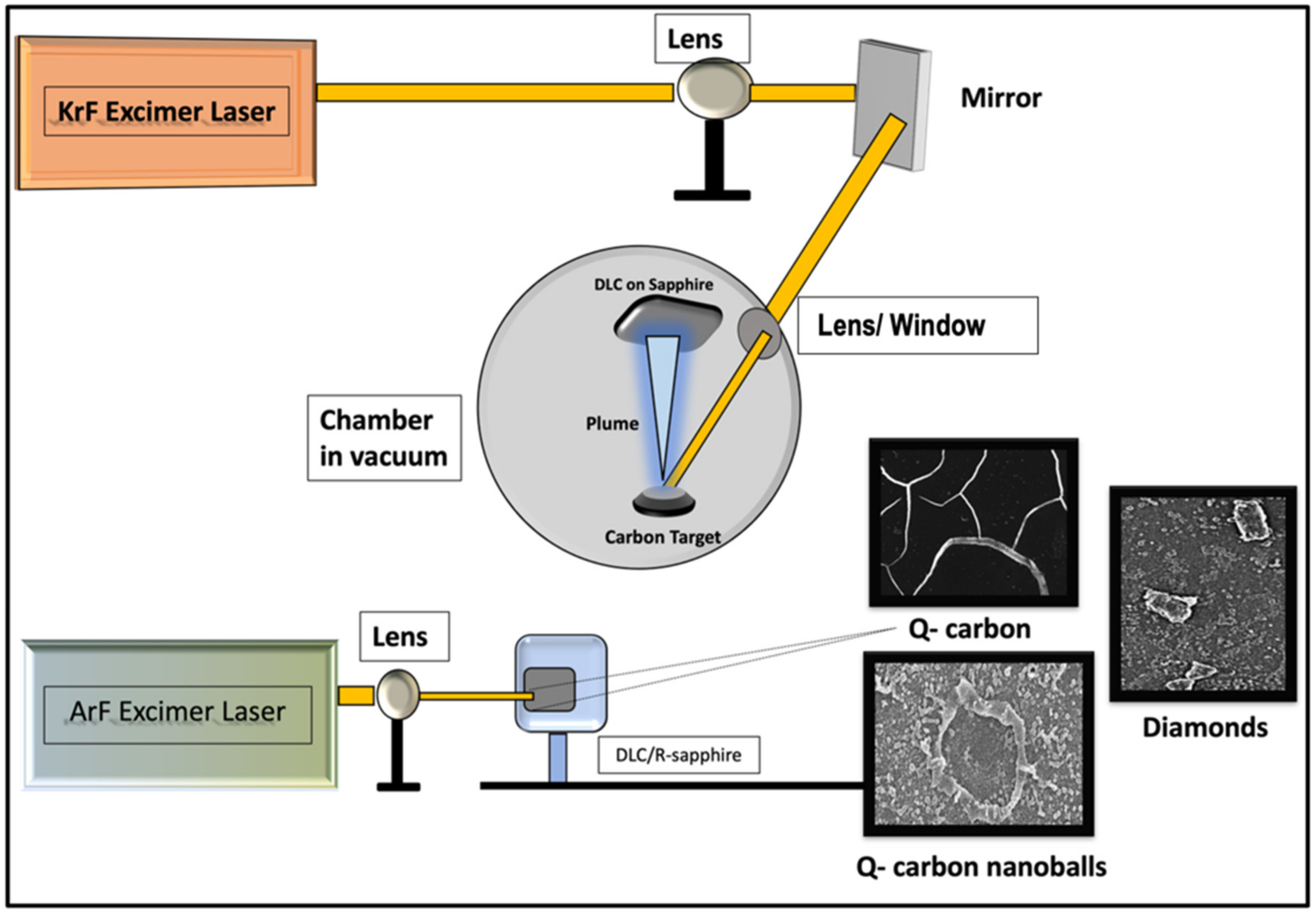
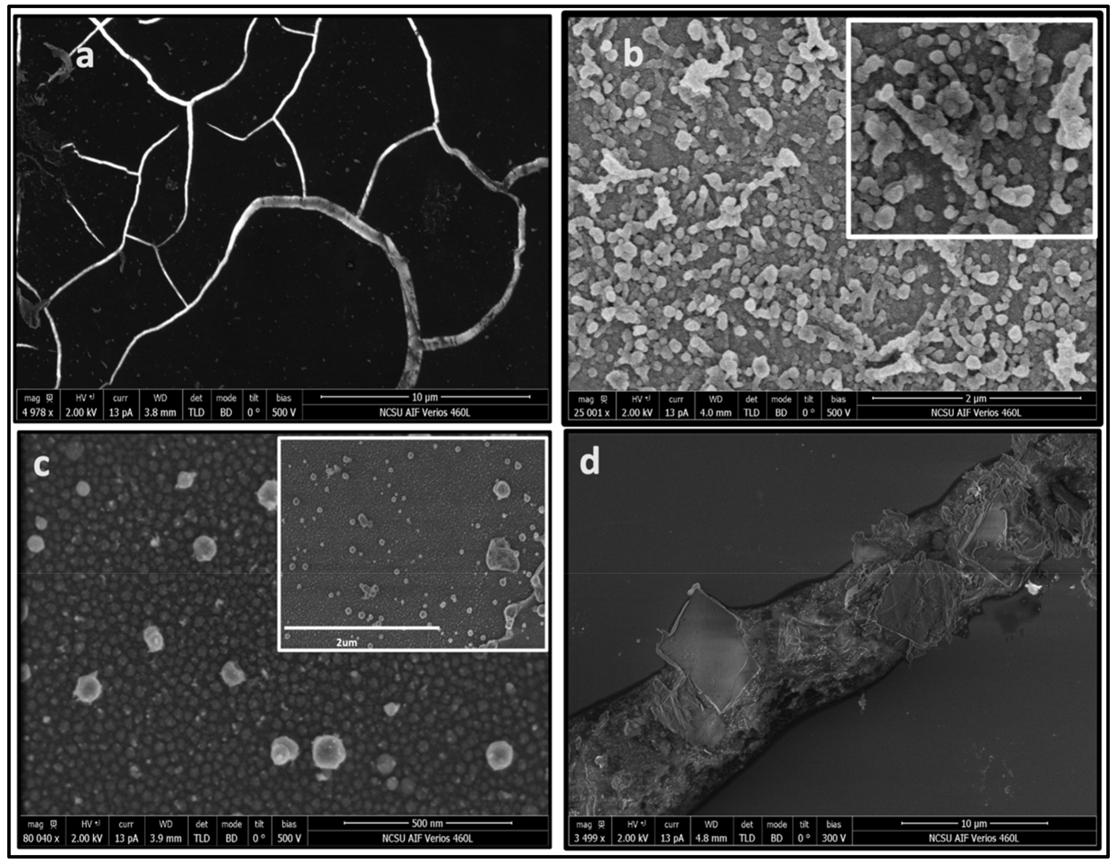
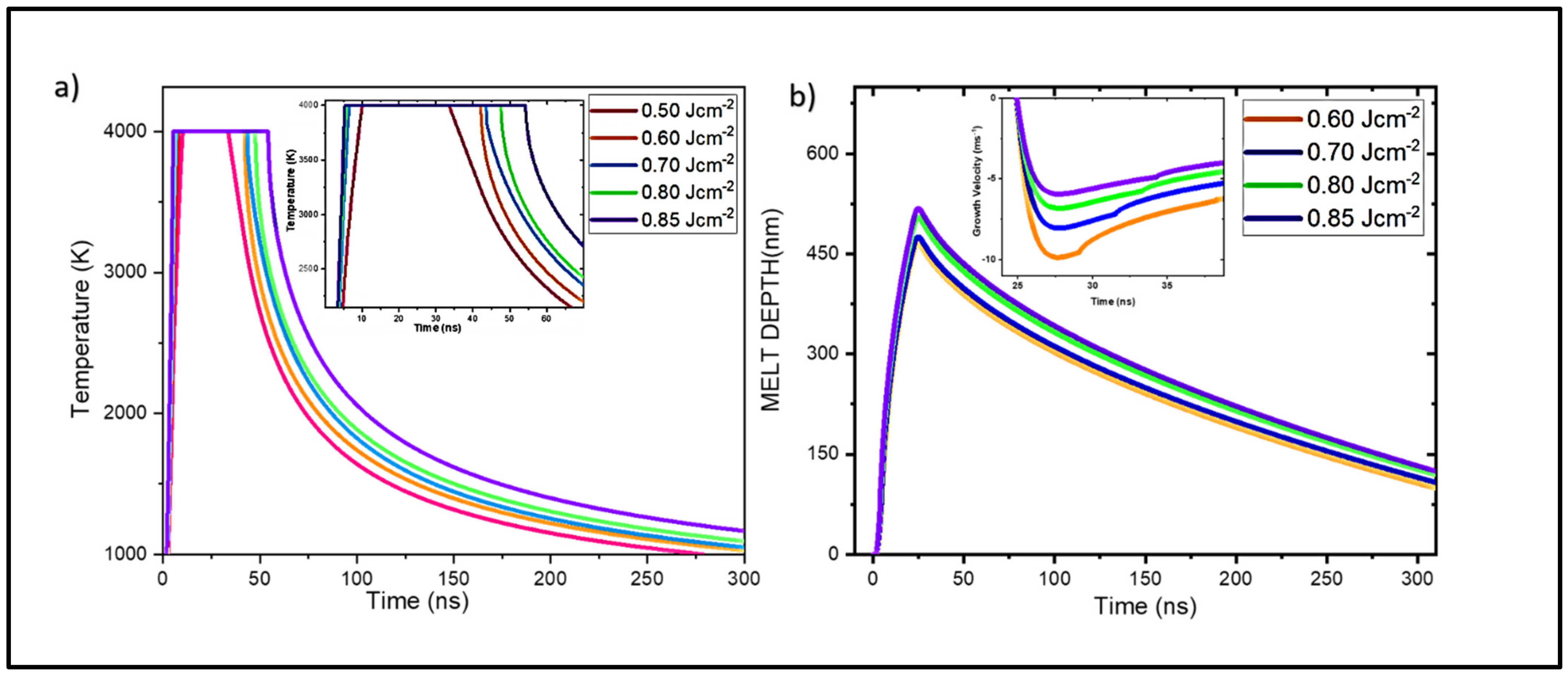
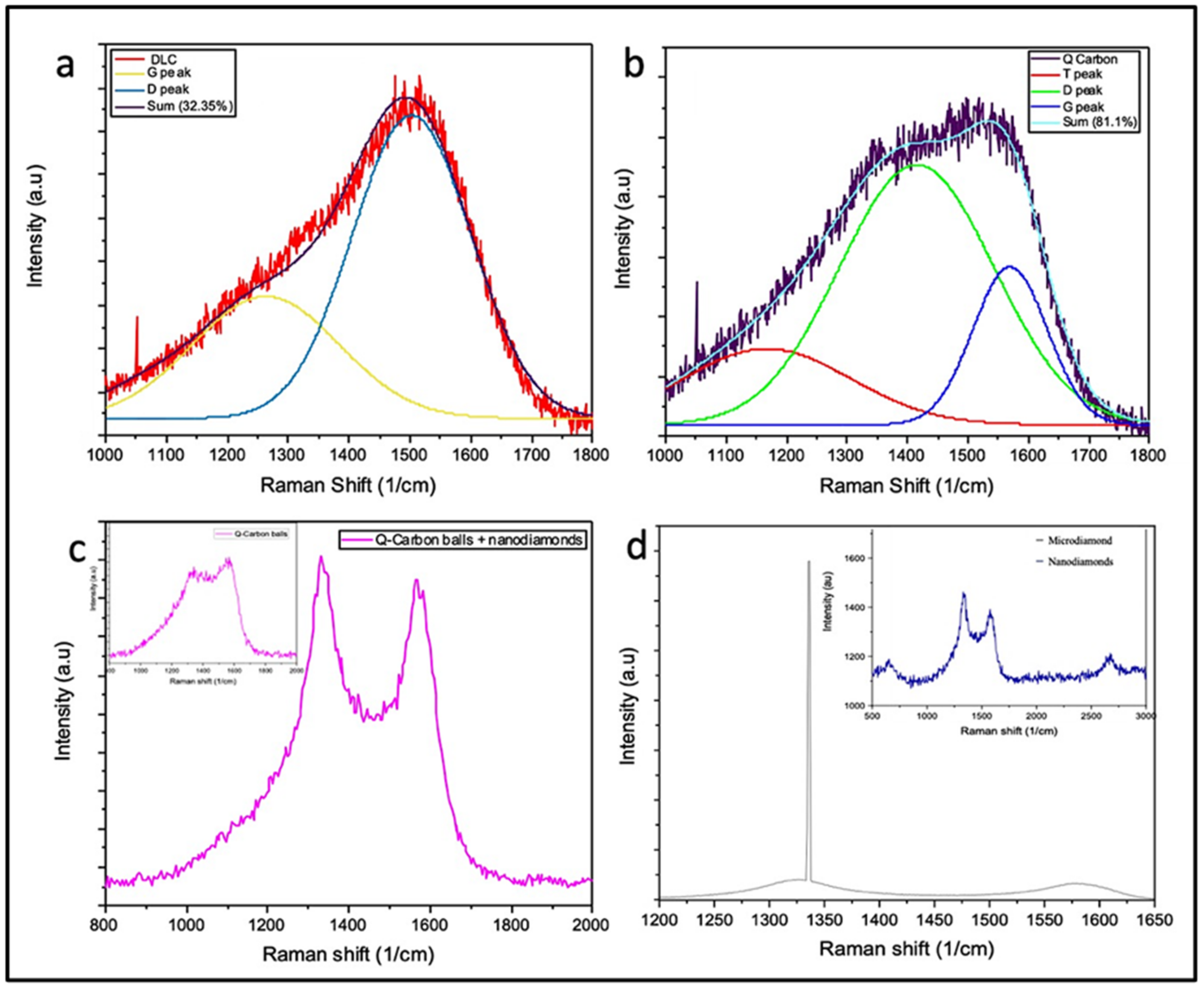
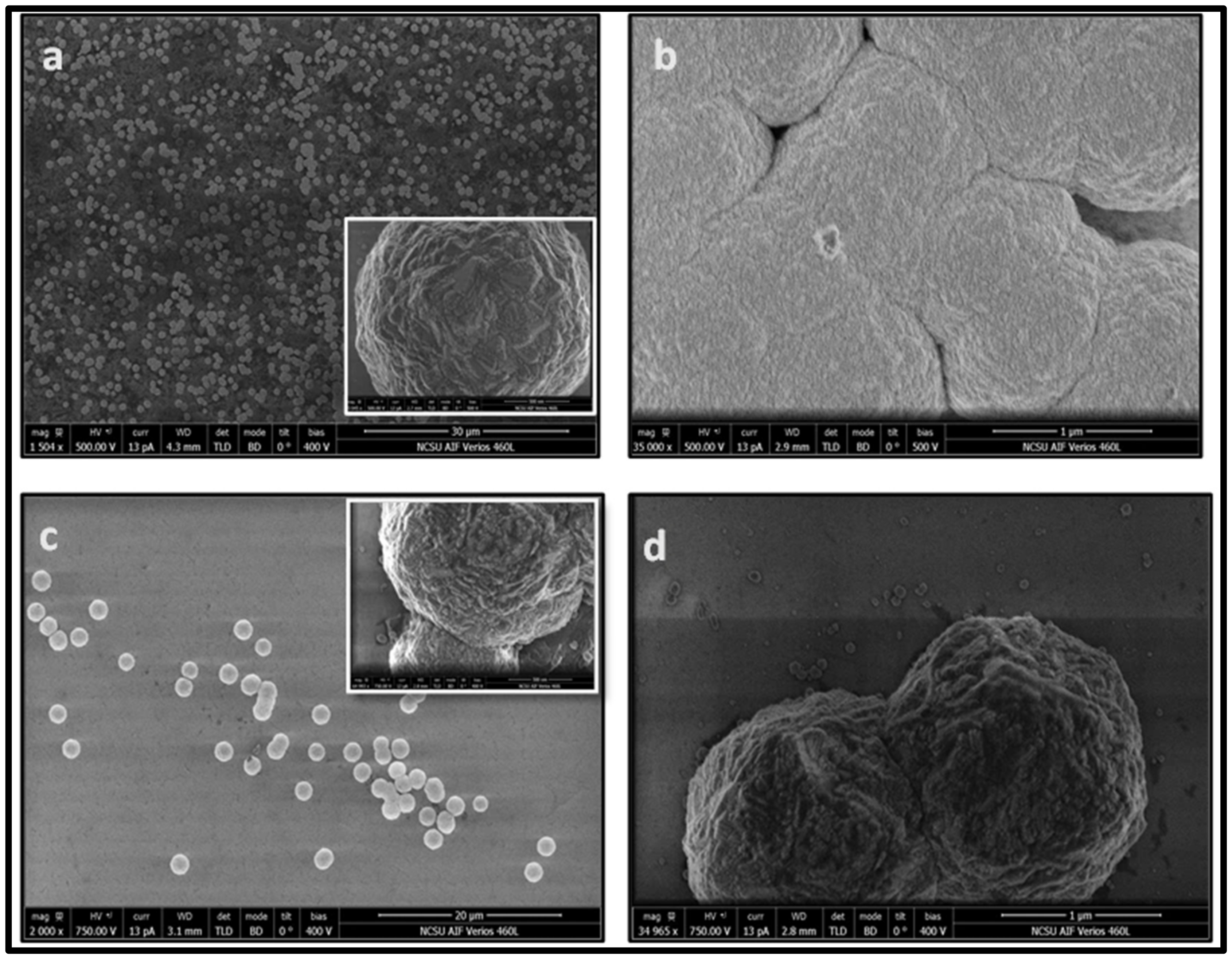
3.1. Formation of Structures by PLA

When the amorphous carbon layer is annealed by the nanosecond pulse laser in PLA, rapid melting occurs, leading to the super undercooled state, which can be quenched to form Q-carbon or Q-carbon nanoballs embedded with nanodiamonds or microdiamonds. By using nanosecond laser pulses (pulse duration 20–25 ns), the whole process is completed in a fraction of a microsecond. The formation of these metastable structures depends upon the degree of undercooling. To understand the effect of phase formation of liquid carbon to Q-carbon or diamond, we have derived the following equation by using the Clausius Clapeyron equation ( d P / d T = Δ H / T Δ V ) to relate the change of pressure with time to the quenching rate d T d t and the undercooling ( Δ T ):
d P d t = d P d T d T d t = Δ T Δ H m Δ T m . T . Δ V   d T d t = C . Δ T d T d t
where Δ Hm is the change in enthalpy of the melt, Δ V is the volume change during the transformation, T is the temperature of transformation close to the melting point Tm, Δ T is undercooling and C is the constant Δ H m Δ T m . T . Δ V   .
By increasing the quenching rate ( d T d t ), and controlling the undercooling ( Δ T ), it is possible to achieve direct conversion of carbon into diamond or novel phases of Q-carbon. There is a rapid increase in d P d t   with a large undecooling Δ T and the increasing quenching rate, which control the formation of Q-carbon and diamond phases. With an undercooling of the order of 1000 K, the diamond phase is formed, and at a still higher undercooling Q-carbon phase is formed, as estimated by SLIM simulation studies [14].
In this paper, we focus on varying the annealing energy density on the DLC film of constant thickness to change the quenching rate and undercooling to form tailored Q-carbon structures in the form of 2D film, 3D nanoballs/ diamond composites, or pure diamond film. We have analyzed the phase transformation of amorphous carbon into these carbon polymorphs using the nanosecond laser–solid melt interactions using SLIM computer simulation modeling. This software takes into account thermal and temperature dependent optical properties of the film and the substrate material, and laser pulse characteristics to calculate formation and evolution of melt interfaces on laser irradiation.
Figure 2a shows the temperature vs. time plot after the irradiation of the carbon film with different annealing energy density (0.50 J cm−2 –0.85 J cm−2). For the formation of Q-carbon, diamond, and its composites, it is essential to melt the DLC film with a large undercooling. Due to the low thermal conductivity of sapphire, it traps heat flow, resulting in high undercooling at the substrate/melt interface. Once the surface melting occurs, the melt-front propagates downwards towards the substrate with the latent heat of fusion and heat conduction driving it forward. The melting threshold energy density is found to be 0.5 J cm−2 when irradiated with the ArF laser. This matches with the experimental results of the surface melting of carbon at 0.5 J cm−2 irradiation. The melting starts at ~4 ns, with the temperature reaching maximum at ~20 ns, corresponding to the ArF laser pulse duration. The flatter region in the profile shows homogeneous carbon melt wherein, the molten carbon remains in the melt state for some time and then cools down rapidly, leading to different regrowth velocity rates.
With the increasing pulse energy density, we see that the maximum surface temperature persists for a longer time, after which it starts cooling. The values of undercooling and solid regrowth velocities achieved during the cooling determine the phase that grows. We investigate the melt depth profile beyond the onset of melting in Figure 2b, which shows melt depth as a function of time for different energy densities. It reveals that the melt depth increases with the increase in the melt lifetime. The melt depth also increases with the increase in annealing energy density. We use the derivative of the melt profile graph to find the growth velocity, as shown in Figure 2) inset. It is found that regrowth rates ranging from 5.8 ms−1 to ~6.5 ms−1 for 0.80 J cm−2 and 0.85 J cm−2, respectively, are favorable for diamond growth. In the range of 0.60 J cm−2 to 0.70 J cm−2, we see a comparatively shorter carbon melt lifetime and rapid quenching, leading to a higher undercooling and regrowth velocities of ~10 ms−1. In this range, we see the formation of Q-carbon and Q-carbon nanoballs, as confirmed by our experiment. With the increase in undercooling and higher quenching rate, we get an increased regrowth velocity rate. As the regrowth velocity decreases with distance from the surface, the carbon atoms have sufficient time to rearrange, forming crystalline nanodiamonds.
Figure 3 shows high resolution scanning electron microscope (SEM) images of the samples annealed at different energy densities. At the laser energy density of 0.6 J cm−2 (Figure 3a), we see the formation of Q-carbon layer near the substrate interface with the α-carbon overlayer, in which cracks are formed upon quenching due to differences in the coefficients of thermal expansion of Q-carbon and α-carbon layers. At the laser energy density of 0.7 J cm−2, we observe the formation of Q-carbon nanoballs (Figure 3b). These samples also contain embedded nanodiamonds, which nucleate and grow from these Q-carbon structures. This agrees with previous reports demonstrating that the Q-carbon phase provides nuclei for diamond growth [28]. It is interesting to note that these nanoballs are self-organized in the form of rings. The formation of ring structures occurs as a result of diamond tetrahedral alignment along the <110> direction, where these tetrahedra can pivot along the <001> direction to form a ring structure [28]. These nanoballs have a fairly uniform size of about 50nm. We see nanocrystallites coagulated with each other to form bigger clusters, leading to the formation of other functional structures [29]. On increasing the energy density of the laser to 0.80 J cm−2 and 0.85 J cm−2, we observe the formation of microdiamonds and nanodiamonds. The structure of Q-carbon consists of diamond tetrahedra with center atoms, which are arranged randomly with the bonding within the tetrahedra sp3 and in between sp2. It should be noted that in the diamond, each unit cell has four tetrahedra with a center atom and four tetrahedra without them. During laser annealing, the formation of different structures depends on the substrate thickness, the sp3 to sp2 ratio governed by the laser energy density, and the conductivity of the sample. The Figure 3c shows a uniform distribution of nanodiamonds throughout the sample. The inset shows a large-area nanodiamond coverage, whereas Figure 3d shows that at 0.8 J cm−2 there is a formation of single and cluster microdiamonds and nanodiamonds on r-sapphire. These platelet-looking microdiamonds are all oriented in a <100> direction with respect to the substrate leading to epitaxial growth. The surface morphology of these diamonds appeared more homogeneous with the film comprising of highly dense packing of these nanodiamond crystallites having defined edges in (c). Such nanodiamond structures can be doped with N and Si to form NV and SiV color centers, which are needed for nanosensing and quantum computing applications. These nanodiamonds range in size from 5 nm to 20 nm. Our previous studies have demonstrated that it is possible to trap a single NV center in a 5 nm nanodiamond within the bulk rather than at the surface for larger sizes, in agreement with theoretical calculations [1].
The bonding characteristics of these carbon polymorphs were studied by using Raman spectroscopy, as the Raman peaks provide signature bonding relations in different structures of carbon. Figure 4 shows the Raman spectra of the four samples. It is well known that PLA on DLC films changes the sp3 and sp2 content in the films [18,30,31]. The as-deposited DLC coated sample shows an amorphous carbon peak broadening with the sp3 content of about 32%, as shown in Figure 4a. During PLA, we form sp3 rich phase of Q-carbon due to higher undercooling and rapid quenching. The Q-carbon spectrum confirms the presence of Q-carbon formation with an increased sp3 content of roughly ~81% with the flatter curve with peaks between 1340 cm−1 (D) and 1560 cm−1 (G). A small peak near 1140 cm−1 is associated with strained sp2 carbon at the interface of the sp3 nanoclusters, as shown in Figure 4b. Gaussian distribution was used for curve fitting and deconvolution of the peaks.
The spectrum of Q-carbon balls embedded with nanodiamonds gave a peak at ~1330 cm−1, as shown in Figure 4c. Diamond is a monoatomic system, with a first-order peak with the symmetry T2g at 1332 cm−1, which is the only Raman active mode. This mode in diamond corresponds to the vibrations associated with two interpenetrating cubic sublattices [32]. Formation of nanodiamonds is attributed to a high undercooling, which causes homogeneous nucleation in the melt state. Figure 4d shows the nanodiamond peak at 1328 cm−1, which is a red shift (of 4 cm−1), and the spectral broadening is due to the phonon confinement effect in nanodiamonds, as shown in HRSEM. The 1334.1 cm−1 peak is observed with microdiamonds, which shows a blue shift due to stress in the film. This is a characteristic diamond peak obtained on the platelet-looking microdiamonds, as shown in Figure 3d. The growth orientation depends on DME (Domain Matching Epitaxy) and the substrate having 2-axis symmetry, which promotes <100> growth for the r-sapphire. These microdiamonds are all oriented in a similar direction with respect to the substrate, which corelates to the DME growth of the <100> diamond on r-sapphire.
The Q-carbon demonstrates robust coercivity and associated ferromagnetism at room temperature due to the presence of dangling bonds with unpaired spins at the sp3/sp2 interface [28]. The formation of Q-carbon is further confirmed by the magnetic results. Figure 5 shows the magnetization vs. the magnetic field plot of the Q-carbon sample. Controlled samples containing only diamond, diamond-like carbon, and sapphire substrate exhibit only diamagnetic behavior, which was subtracted in the represented magnetic plots. There is a typical ferromagnetic loop having a finite coercivity, observed with the variation of temperature (10 K, 100 K, and 300 K), as shown in Figure 5. The room temperature ferromagnetism is observed in Q-carbon with a finite coercivity of 57.5 Oe. The coercivity at 10 K is 76 Oe, which decreases with the increase in temperature. DLC film shows the diamagnetic behavior before laser annealing [1].

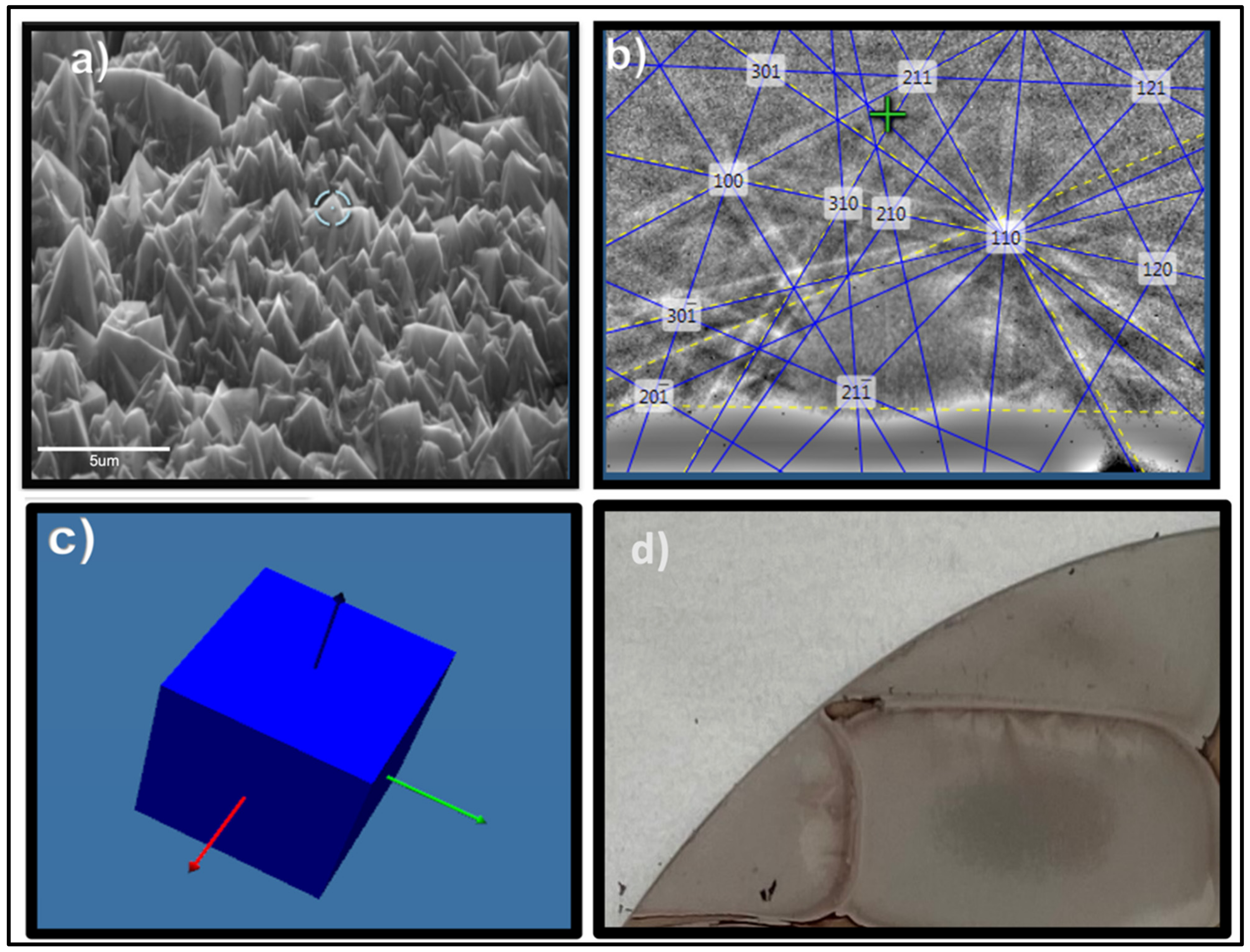
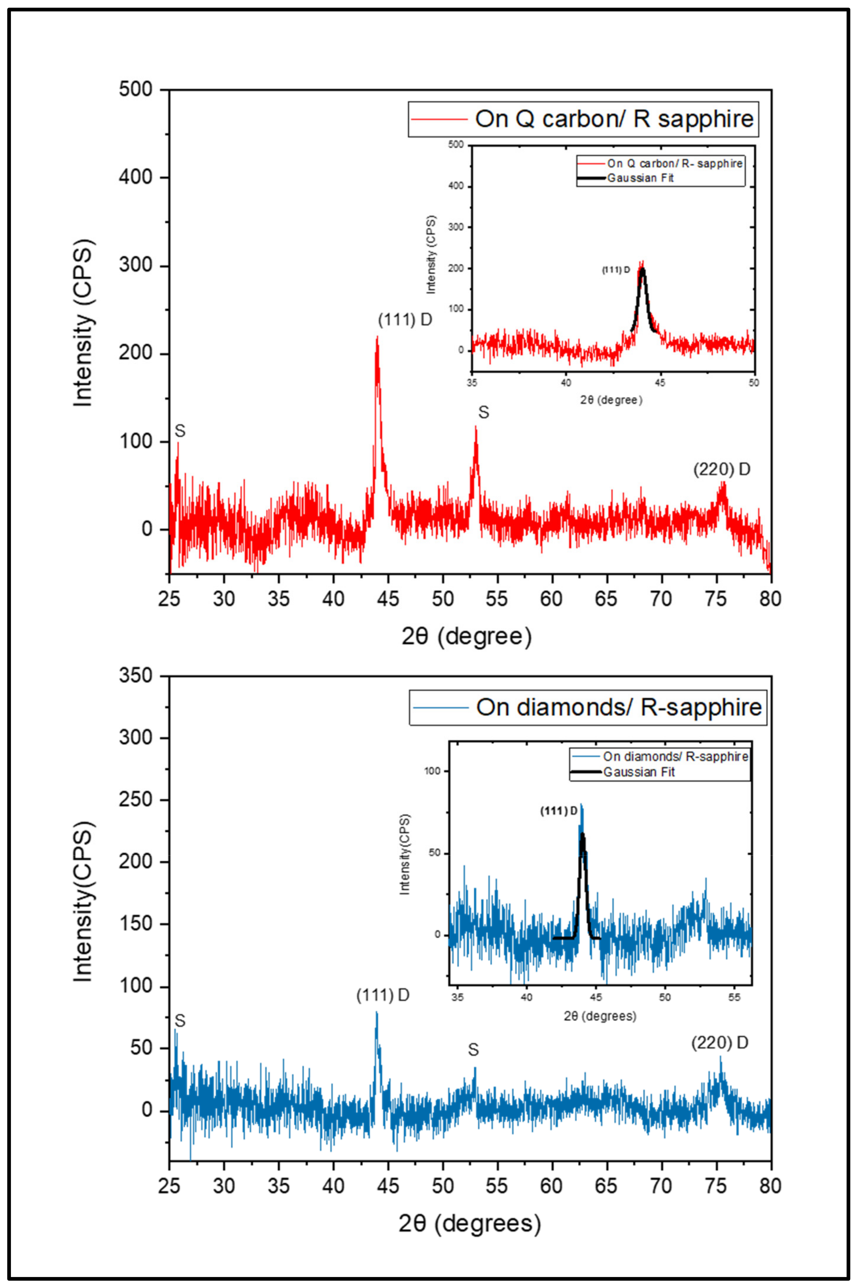
3.2. HFCVD Samples Analysis: Formation of Nano- to Microdiamonds on R-Sapphire

The films formed in the PLD/PLA process are very adherent because of the formation of liquid carbon that reacts with the sapphire to form a couple of monolayers of aluminum carbide, which stitches to the film, making it adherent. The reaction is:
2 A l 2 O 3   s + 6 C   l = A l 4 C 3   s + 3 C O 2   g
Therefore, the use of these films for CVD diamond growth provides the additional advantage of adherence, besides the easy nucleation of diamond. We use the Q-carbon and diamond as seeds to produce large-area diamond films by HFCVD. During the HFCVD process, the hot tungsten filaments have a temperature of ~2000 °C. When the hydrogen molecules hit it, they split into hydrogen atoms, which react with methane until carbon atoms are attached to existing sp3 bonded nuclei sites [33]. The presence of diamond tetrahedra in Q-carbon provides a diamond nucleation site. Thus, the Q-carbon provides the template for the continuous diamond growth, as observed in the SEM images in Figure 6a. Therefore, we obtain a larger area coverage during HFCVD growth. The results were similar in Q-carbon monolayers and Q-carbon nanoballs. The microdiamonds have an average size of 2 μm. Without Q-carbon, scattered and less area coverage with microdiamonds is seen due to lack of nucleation sites, as shown in Figure 6c. However, these samples exhibited a bigger diamond of average size about 2.5 μm for the nucleation, as the precursor isolated microdiamonds, as compared to the continuous Q-carbon. The larger size was attributed to the larger size of seeds (average size ~1 μm) on which diamond growth by CVD occurs. These microdiamonds are ballas type and crystalline with facets. The ballas type are nearly pure diamonds with prominent twinned microstructures [34]. Due to the presence of micro-twins, the cleavage and crack propagation along crystallographic planes can be expected to be much lower in ballas than in single-crystalline diamond and has higher hardness similar to pure diamond [35]. Thus, they are potential candidates for wear applications. Ballas type diamond containing nanodiamonds could also be of interest for flat panel displays. Figure 6b,d show the FESEM micrographs of the microdiamonds at lower magnification in the sample with Q-carbon and nanodiamonds as a seed, respectively. The results demonstrate the growth rate of ~0.6 μm/hr. The diamond formed has <111> and <100> growth orientation on the films, which is confirmed later by XRD characterizations. At the Q-carbon-sapphire interface, we see the diamond nucleation as shown in Figure 6b. The growth orientation depends on DME and the substrate orientation. By the Domain matching epitaxy, we see the epitaxial growth of diamond, as the diamond nucleation originates at the interface with the substrate [12].
Figure 7a shows the formation of <100> oriented crystalline diamond over a large area. These crystallites have {111} facets with <100> axis normal to the substrate. Figure 7b shows the EBSD pattern at 70° and Figure 7c shows the corresponding orientation relationship diagram to confirm the crystal structure of the <100> diamond growth. The formation of this microstructure with sharp edges is ideal for field emission and display device applications. The domain matching epitaxial alignment of (100) diamond on (101 2) sapphire is as follows: <200> diamond //< 2(11) 0> sapphire along a- axis, and <020> diamond //<−1101> along b-axis. This misfit over 25% can be handled by the domain matching epitaxy, where the integral multiples of the film and the substrate planes match across the interface [36]. The Figure 7d shows the wafer-scale integration by the overlapping of laser pulses to create large area Q-carbon/ diamond structures. The capabilities of 100 Hz in our ArF laser system creates the output of 100 cm2 s−1.
Figure 8 shows Raman spectra of microdiamond films after CVD growth. We observe the characteristic T2g peak of diamond from the Q-carbon seeded sample at 1332.5 cm−1, which is indicative of fairly stress-free diamond films. In the case of the diamond-seeded sample, the Raman peak upshifts to 1333.2 cm−1, which is indicative of residual compressive strain. It should be noted that diamond seeded samples demonstrate a much higher fraction of disordered amorphous carbon, at ~1500 cm−1, which forms in between the seeds. The stresses in thin films are due to the differences in the coefficient of thermal expansion between the film and the substrate, which causes a shift ( Δ v) in the Raman peak [37]. Here, we assume that the thermal strain dominates, and the defects and lattice strains are negligible, as these strains are fully relaxed by the DME paradigm. The shift in the Raman peak and the associated stresses in the films can be expressed as:
Δ v = v s     v 0 = α σ
and
σ = 2 µ 1 + v   Δ α .   Δ T / 1 v
where vs is the T2g diamond peak, vo = 1332 cm−1 is the unstressed diamond peak, α is Raman stress factor, σ is the inplane balanced biaxial stress, µ is the shear modulus of the film, v is the Poisson’s ratio, Δ α is the difference in the coefficient of thermal expansion between the diamond film and the substrate, and Δ T   is the difference between the growth and the ambient temperatures. Equation (3) indicates a Raman peak shift of −1.2 cm−1 in the case of the diamond seeded sample. The calculated stress from the Eqiation (4) in the film is ~3 GPa for the diamond-seeded sample, whereas negligible stress is observed in the Q-carbon-seeded samples. A decrease in stress is useful for the formation of crack-free and highly adherent films. The type of microdiamond formed here are (100) ballas diamond, as shown in previous studies [38]. During the structural changes, it is observed that the intensity of the diamond T2g peak decreases because of enhanced micro-twinned regions. Moreover, also observed is the rise in the G peak with increasing amounts of micro-twinned areas in the samples without Q-carbon.
We carried out XRD analysis to confirm the formation of (111) or (100) diamond. XRD is a powerful characterization tool for the analysis of the stress value averaged over the entire film [39]. Figure 9 shows the XRD results of the films. In the Q-carbon sample, we see (111) a characteristic diamond peak at 2θ of 43.9°, and (220) peak at 75.4° [40]. We observe a relatively lower intensity of the (111) peak in the diamond sample showing the peak at 43.88°. The relative intensity of the (111) diamond peak is related to the coverage in the film in agreement with the SEM results. A (220) peak is observed at 75.38° in the diamond-seeded sample. We performed a grazing incidence XRD analysis to account for small intensity peaks from the substrate. We observe tiny sapphire peaks at 25.8° and 52.9° from the (1 1 ¯ 02) and (2 2 ¯ 04) planes. To find the average crystallite size, we use the Scherer equation:
L   c r y s t a l l i t e   s i z e = K λ / β cos θ  
The value of K is 0.9 for gaussian fit, λ is the wavelength of Cu Kα radiation, which is 0.154 nm, β is the full width half maxima (FWHM) of the diamond peak in radians, which was found to be 0.0078 rad (0.45°), and θ is the Bragg diffraction angle (in radians), which was calculated to be 0.38 rad (21.9°). From this, the average crystallite size (L) was calculated to be 19.1 nm. This represents a high quality nanocrystalline film. Film characteristics such as fracture toughness, decohesion energies, and electrical conductivity vary greatly in this crystallite size range. Previous studies have demonstrated a higher diamond content at the grain boundaries in the nanocrystalline diamond [41].

4. Conclusions

In summary, we demonstrate the formation of Q-carbon tailored as 2D films and 3D nanoballs with embedded nanodiamonds, and pure diamond structures by changing the annealing energy density on a single substrate, and further use them to form large-area diamond films by HFCVD. We change the laser annealing energy density to modify the sp3 content in a DLC film of constant thickness to form these structures, wherein the choice of these parameters was guided by SLIM modeling. For a constant film thickness, we obtained microstructures ranging from Q-carbon layers and nanoballs to nanodiamonds and microdiamonds with increasing pulse energy density. This is related to decreasing undercooling with increasing pulse energy density. These films undergo melting and subsequent quenching during PLA, wherein the rate of undercooling is the key for the growth of these structures. At a lower energy density in PLA, we see the formation of uniform 2D Q-carbon structures, which evolve into strings/rings of self-organized Q-carbon nanoballs on increasing the energy density. This unique feature of self-organization into nanoballs has several interesting applications. It is envisaged that these Q-carbon nanoballs can be harder than Q-carbon films with robust ferromagnetism and, therefore, find applications in drug coating and target delivery. These nanoballs have embedded nanodiamonds, making them a suitable Q-carbon/diamond composite. Minimizing the undercooling at even higher energy density, we form a homogeneous film comprising of densely packed nanodiamonds (5–20 nm), which can serve as active N-V sites upon doping with N. We observed <100> oriented microdiamonds with a little increase in the energy density. We rationalize microstructures using a framework demonstrating that the undercooling and quenching rate can generate a pressure pulse, which is the key to the formation of these nonequilibrium structures. This ability to selectively tune between diamond or Q-carbon or their composites is highly desirable for various applications ranging from targeted drug delivery, field emission, protective coating, and nanosensing applications. Furthermore, we use Q-carbon/diamond composite and nanodiamonds as seeds to grow microdiamonds by HFCVD. It is observed that the Q-carbon nanoballs were more effective as seeds, as they provided a higher number of active nucleation sites and resulted in stress-free, denser, and adherent films. The ballas type of diamonds formed here are reportedly harder and stronger and its combination with Q-carbon composite as seeds make them a suitable candidate in wear and display applications. The <100> faceted diamond formed is ideal for field emission and display device applications. This study opens the door to the fabrication of carbon polymorphs by the basic understanding of the laser–solid interactions in thin films and tuning between the structures by changing the energy density of the laser. We can form and selectively tune between these structures based on laser parameters for a variety of biomedical applications, nanosensing and other quantum devices operating at room temperature.

Author Contributions

Conceptualization and theory, J.N.; methodology, N.K.; formal analysis, N.K.; data curation, N.K.; writing—original draft preparation, N.K.; writing—review and editing, N.K. and J.N.; supervision, J.N.; funding acquisition, J.N. All authors have read and agreed to the published version of the manuscript.

Funding

This research was funded by the National Science Foundation Grant (DMR-2016256).

Institutional Review Board Statement

Not applicable.

Informed Consent Statement

Informed consent was obtained from all subjects involved in the study.

Data Availability Statement

The datasets generated during and/or analyzed during the current study are available from the corresponding author on reasonable request.

Acknowledgments

This work was supported by the National Science Foundation Grant (DMR-2016256). The comments and discussions with John Prater are gratefully acknowledged. This work was performed in part at the Analytical Instrumentation Facility (AIF) at North Carolina State University, which is supported by the State of North Carolina and the National Science Foundation (award number ECCS-2025064). The AIF is a member of the North Carolina Research Triangle Nanotechnology Network (RTNN), a site in the National Nanotechnology Coordinated Infrastructure (NNCI).

Conflicts of Interest

The authors declare no conflict of interest. The funders had no role in the design of the study; in the collection, analyses, or interpretation of data; in the writing of the manuscript, or in the decision to publish the results.

References

  1. Narayan, J.; Bhaumik, A.; Gupta, S.; Haque, A.; Sachan, R. Progress in Q-carbon and related materials with extraordinary properties. Mater. Res. Lett. 2018, 6, 353–364. [Google Scholar] [CrossRef] [Green Version]
  2. Haque, A.; Narayan, J. Stability of electron field emission in Q-carbon. MRS Commun. 2018, 8, 1343–1351. [Google Scholar] [CrossRef]
  3. Narayan, J.; Joshi, P.; Smith, J.; Gao, W.; Weber, W.J.; Narayan, R.J. Q-carbon as a new radiation-resistant material. Carbon 2022, 186, 253–261. [Google Scholar] [CrossRef]
  4. May, P.W. Diamond Thin Films: A 21st-Century Material. Philos. Trans. R. Soc. Lond. Ser. A 2000, 358, 473–495. [Google Scholar] [CrossRef]
  5. Bray, K.; Kato, H.; Previdi, R.; Sandstrom, R.; Ganesan, K.; Ogura, M.; Makino, T.; Yamasaki, S.; Magyar, A.P.; Toth, M.; et al. Single Crystal Diamond Membranes for Nanoelectronics. Nanoscale 2018, 10, 4028–4035. [Google Scholar] [CrossRef] [Green Version]
  6. Nunn, N.; Torelli, M.; McGuire, G.; Shenderova, O. Nanodiamond: A high impact nanomaterial. Curr. Opin. Solid State Mater. Sci. 2017, 21, 1–9. [Google Scholar] [CrossRef]
  7. Bundy, F.P.; Bassett, W.A.; Weathers, M.S.; Hemley, R.J.; Mao, H.U.; Goncharov, A.F. The pressure-temperature phase and transformation diagram for carbon; updated through 1994. Carbon 1996, 34, 141–153. [Google Scholar] [CrossRef]
  8. Das, D.; Singh, R.N. A review of nucleation, growth and low temperature synthesis of diamond thin films. Int. Mater. Rev. 2007, 52, 29–64. [Google Scholar] [CrossRef]
  9. Sachan, R.; Hachtel, J.A.; Bhaumik, A.; Moatti, A.; Prater, J.; Idrobo, J.C.; Narayan, J. Emergence of shallow energy levels in B-doped Q-carbon: A high-temperature superconductor. Acta Mater. 2019, 174, 153–159. [Google Scholar] [CrossRef]
  10. Sun, Y.P.; Zhou, B.; Lin, Y.; Wang, W.; Fernando, K.A.S.; Pathak, P.; Meziani, M.J.; Harruff, B.A.; Wang, X.; Wang, H.; et al. Quantum-sized carbon dots for bright and colorful photoluminescence. J. Am. Chem. Soc. 2006, 128, 7756. [Google Scholar] [CrossRef]
  11. Cui, L.; Ren, X.; Sun, M.; Liu, H.; Xia, L. Carbon Dots: Synthesis, Properties and Applications. Nanomaterials 2021, 11, 3419. [Google Scholar] [CrossRef] [PubMed]
  12. Narayan, J.; Larson, B.C. Domain epitaxy: A unified paradigm for thin film growth. J. Appl. Phys. 2003, 93, 278–285. [Google Scholar] [CrossRef]
  13. Gupta, S.; Sachan, R.; Bhaumik, A.; Narayan, J. Enhanced mechanical properties of Q-carbon nanocomposites by nanosecond pulsed laser annealing. Nanotechnology 2018, 29, 45LT02. [Google Scholar] [CrossRef] [PubMed]
  14. Gupta, S.; Sachan, R.; Bhaumik, A.; Pant, P.; Narayan, J. Undercooling driven growth of Q-carbon, diamond, and graphite. MRS Commun. 2018, 8, 533–540. [Google Scholar] [CrossRef]
  15. Riley, P.R.; Joshi, P.; Khosla, N.; Narayan, J.; Narayan, R. Formation of Q-Carbon with Wafer Scale Integration. SSRN 2022, 1–26. [Google Scholar] [CrossRef]
  16. Joshi, P.; Gupta, S.; Haque, A.; Narayan, J. Fabrication of ultrahard Q-carbon nanocoatings on AISI 304 and 316 stainless steels and subsequent formation of high-quality diamond films. Diam. Relat. Mater. 2020, 104, 107742. [Google Scholar] [CrossRef]
  17. Gupta, S.; Bhaumik, A.; Sachan, R.; Narayan, J. Structural Evolution of Q-carbon and Nanodiamonds. JOM 2018, 70, 450–455. [Google Scholar] [CrossRef]
  18. Yoshinaka, H.; Inubushi, S.; Wakita, T.; Yokoya, T.; Muraoka, Y. Formation of Q-carbon by adjusting sp3 content in diamond-like carbon films and laser energy density of pulsed laser annealing. Carbon 2020, 167, 504–511. [Google Scholar] [CrossRef]
  19. Singh, R.K.; Narayan, J. A novel method for simulating laser-solid interactions in semiconductors and layered structures. Mater. Sci. Eng. B 1989, 3, 217–230. [Google Scholar] [CrossRef]
  20. Narayan, J.; Bhaumik, A.; Gupta, S.; Joshi, P.; Riley, P.; Narayan, R.J. Formation of self-organized nano-and micro-diamond rings. Mater. Res. Lett. 2021, 9, 300–307. [Google Scholar] [CrossRef]
  21. Zhao, T.C.; Yuan, J.L.; Deng, Q.F.; Feng, K.P.; Xu, W. Contrast Experiments in Dielectrophoresis Polishing (DEPP)/Chemical Mechanical Polishing (CMP) of Sapphire Substrate. Appl. Sci. 2019, 9, 3704. [Google Scholar] [CrossRef] [Green Version]
  22. Aida, H.; Doi, T.; Takeda, H.; Katakura, H.; Kim, S.-W.; Koyama, K.; Yamazaki, T.; Uneda, M. Ultraprecision CMP for sapphire, GaN, and SiC for advanced optoelectronics materials. Curr. Appl. Phys. 2012, 12, S41–S46. [Google Scholar] [CrossRef]
  23. Xu, L.; Zou, C.; Shi, X.; Pan, G.; Luo, G.; Zhou, Y. Fe-Nx/C assisted chemical–mechanical polishing for improving the removal rate of sapphire. Appl. Surf. Sci. 2015, 343, 115–120. [Google Scholar] [CrossRef]
  24. Aharonovich, I.; Greentree, A.D.; Prawer, S. Diamond photonics. Nat. Photonics 2011, 5, 397–405. [Google Scholar] [CrossRef]
  25. Liang, J.; Nakamura, Y.; Zhan, T.; Ohno, Y.; Shimizu, Y.; Katayama, K.; Watanabe, T.; Yoshida, H.; Nagai, Y.; Wang, H.; et al. Fabrication of high-quality GaAs/diamond heterointerface for thermal management applications. Diam. Relat. Mater. 2021, 111, 108207. [Google Scholar] [CrossRef]
  26. Singh, R.K.; Narayan, J. Pulsed-laser evaporation technique for deposition of thin films: Physics and theoretical model. Phys. Rev. B 1990, 41, 8843. [Google Scholar] [CrossRef] [PubMed]
  27. Steinbeck, J.; Dresselhaus, G.; Dresselhaus, M.S. The properties of liquid carbon. Int. J. Thermophys. 1990, 11, 789–796. [Google Scholar] [CrossRef]
  28. Narayan, J.; Khosla, N. Self-organization of amorphous Q-carbon and Q-BN nanoballs. Carbon 2022, 192, 301–307. [Google Scholar] [CrossRef]
  29. Liz-Marzán, L.M.; Mulvaney, P. The assembly of coated nanocrystals. J. Phys. Chem. B 2003, 107, 7312–7326. [Google Scholar] [CrossRef]
  30. Joshi, P.; Riley, P.R.; Denning, W.; Shukla, S.; Khosla, N.; Narayan, J.; Narayan, R. Laser-patterned carbon coatings on flexible and optically transparent plastic substrates for advanced biomedical sensing and implant applications. J. Mater. Chem. C 2022, 10, 2965–2975. [Google Scholar] [CrossRef]
  31. Panda, M.; Krishnan, R.; Ravindran, T.R.; Das, A.; Mangamma, G.; Dash, S.; Tyagi, A.K. Spectroscopic studies on diamond like carbon films synthesized by pulsed laser ablation. AIP Conf. Proc. 2016, 1731, 080040. [Google Scholar]
  32. Dennison, J.R.; Holtz, M.; Swain, G. Raman spectroscopy of carbon materials. Spectroscopy 1996, 11, 38–45. [Google Scholar]
  33. Zhang, Y.; Li, Z.; Kim, P.; Zhang, L.; Zhou, C. Anisotropic hydrogen etching of chemical vapor deposited graphene. ACS Nano 2012, 6, 126–132. [Google Scholar] [CrossRef] [PubMed]
  34. Haubner, R.; Lux, B. Deposition of ballas diamond and nano-crystalline diamond. Int. J. Refract. Met. Hard Mater. 2002, 20, 93–100. [Google Scholar] [CrossRef]
  35. Bühlmann, S.; Blank, E.; Haubner, R.; Lux, B. Characterization of ballas diamond depositions. Diam. Relat. Mater. 1999, 8, 194–201. [Google Scholar] [CrossRef]
  36. Narayan, J. Recent progress in thin film epitaxy across the misfit scale. Acta Mater. 2013, 61, 2703–2724. [Google Scholar] [CrossRef]
  37. Kuo, C.T.; Lin, C.R.; Lien, H.M. Origins of the residual stress in CVD diamond films. Thin Solid Film. 1996, 290, 254–259. [Google Scholar] [CrossRef]
  38. Haubner, R.; Rudigier, M. Raman characterisation of diamond coatings using different laser wavelengths. Phys. Procedia 2013, 46, 71–78. [Google Scholar] [CrossRef] [Green Version]
  39. Ferreira, N.G.; Abramof, E.; Leite, N.F.; Corat, E.J.; Trava-Airoldi, V.J. Analysis of residual stress in diamond films by X-ray diffraction and micro-Raman spectroscopy. J. Appl. Phys. 2002, 91, 2466–2472. [Google Scholar] [CrossRef] [Green Version]
  40. Fox, B.A.; Stoner, B.R.; Malta, D.M.; Ellis, P.J.; Glass, R.C.; Sivazlian, F.R. Epitaxial nucleation, growth, and characterization of highly oriented,(100)-textured diamond films on silicon. Diam. Relat. Mater. 1994, 3, 382–387. [Google Scholar] [CrossRef]
  41. Gruen, D.M. Nanocrystalline diamond films. Annu. Rev. Mater. Sci. 1999, 29, 211–259. [Google Scholar] [CrossRef]
Figure 1. Schematic of pulsed laser deposition of DLC film on r-sapphire and subsequent pulsed laser annealing (PLA) of the film to form Q-carbon, Q-carbon nanoballs and diamond film based on selective quenching and undercooling by different energy densities.
Crystals 12 00615 g001
Figure 2. SLIM simulation results: (a) Temperature vs. time; (b) melt depth vs. time with inset showing the regrowth velocity plot.
Crystals 12 00615 g002
Figure 3. SEM images at (a) 0.60 J cm−2 showing 2D Q-carbon thin film, (b) 0.70 J cm−2 showing Q-carbon nanoballs with nanodiamonds embedded, (c) 0.80 J cm−2 showing nanodiamonds film, and (d) 0.85 J cm−2 showing microdiamonds on r-sapphire.
Crystals 12 00615 g003
Figure 4. Raman spectra of (a) DLC deposited with low sp3 content, (b) pulsed laser annealing at 0.60 J cm−2 showing Q-carbon film beneath the cracks, (c) PLA at 0.70 J cm−2 showing Q-carbon nanoballs with nanodiamonds embedded and pure Q-carbon balls shown in the inset, and (d) PLA at 0.80–0.85 J cm−2 showing a sharp diamond peak at 1334.1 cm−1 on r- sapphire with the inset showing Raman peak of nanodiamond clusters at 1328 cm−1.
Crystals 12 00615 g004
Figure 5. M-H curve showing room temperature ferromagnetism in Q-carbon composites with finite coercivity. The inset shows the coercivity of the intercepts with field at 300 K.
Crystals 12 00615 g005
Figure 6. SEM (secondary electron mode) micrographs of diamond film grown by HFCVD method at different magnifications using (a,b) Q-carbon seeds, and (c,d) diamonds seeds.
Crystals 12 00615 g006
Figure 7. (a) HRSEM showing the formation of <100> oriented diamond over large area. (b) EBSD pattern at 70°. (c) Orientation relationship diagram showing the crystal structure of <100> diamond growth (d) Optical image of the annealed large-scale integrated wafer.
Crystals 12 00615 g007
Figure 8. Raman spectra obtained from different regions in the CVD microdiamond film grown on (a) Q-carbon/nanodiamond seeds at 1332.5 cm−1 and (b) nanodiamond seeds showing peak at 1333.3 cm−1 on r-sapphire substrate.
Crystals 12 00615 g008
Figure 9. X-ray diffraction pattern by grazing incidence obtained from different regions in the diamond film grown using Q-carbon and diamond seeds.
Crystals 12 00615 g009
Publisher’s Note: MDPI stays neutral with regard to jurisdictional claims in published maps and institutional affiliations.

