1. Introduction
Uranium dioxide (UO
2) has always been a nuclear fuel widely used in pressurized water reactor nuclear power plants due to its high melting point, high irradiation resistance, and good compatibility with cladding and coolants [
1]. However, UO
2 has a low thermal conductivity (7.5 W/m·K at room temperature and 2.8 W/m·K at 1273 K), which results in a radial temperature gradient of 2273–4273 K/cm inside the fuel pellets of UO
2 in the running reactor. The maximum temperature in the center exceeds 1973 K, while at the edge it is only about 873 K; this gradient results in large thermal stresses and cracks. The cracking of pellets may increase the fission gas release rate, and the extremely high temperature at the fuel center may cause fuel irradiation swelling and limit the life of UO
2 fuel [
2,
3,
4,
5].
After the Fukushima nuclear accident in Japan in 2011, the Advanced Fuels Working Group of the U.S. Office of Nuclear Energy adjusted the goal for research and development of the advanced fuel cycle technologies for light water reactors (LWRs) as follows: using standard UO
2–Zr as the reference, improvements should be made to the resistance of fuels to serious accidents, the safety of reactors under conditions for serious accidents, and the performance of fuels under normal conditions via the research and development of accident-tolerant fuels (ATFs) [
6,
7]. Based on the ATF development program, the United States regards UO
2 doped with a second phase as key for studies of the modification of high-performance nuclear fuels and has expended considerable efforts in this endeavor. Improving the thermal conductivity of UO
2 through adding a second phase with excellent performance (high thermal conductivity, a small neutron absorption cross section, high melting point) represents a hotspot for research on advanced nuclear fuels.
As a promising second-phase additive in UO
2 fuel pellets, graphene has a high melting point (~3773 K) and thermal conductivity (~3000 W/(m·K)) at room temperature, and is stable at high temperatures [
8,
9]. T. Yao et al. reported highly thermally conductive and mechanically strong UO
2–graphene composite fuels using a metallurgical approach; the composite fuels possessed greatly improved thermal conductivities (74% and 162 wt.% enhancement at room temperature along the radial direction for 1 wt.% and 5 wt.% graphene composites), and they observed 150% improvement in fracture toughness compared to UO
2 [
8]. D. Zhang et al. reported a hydrothermal approach to synthesize UO
2 and RGO sheets with an enhancement of approximately 35.4% in thermal conductivity [
9]. Current research on UO
2–graphene composite fuels remain in its infancy. In 2016, South Korea evaluated the safety of UO
2–graphene composite fuels under working conditions, and their results showed that, in service, 5% graphene reduced the core temperature of the fuel from 2087 K to 1717 K and the surface temperature of the instantaneously activated cladding from 1228 K to 1125 K, which significantly improved the reactor power density and the maximum allowable fuel consumption [
10].
In this study, a multi-step UO2 wet process was adopted to form an effective and firm combination between UO2 and graphene. In this process, small quantities of gas and liquid were produced, but these gases were collected and treated effectively. A nucleation method based on graphene enabled an in situ synthesis through the reactive deposition of a uranyl nitrate solution and ammonia water on graphene, and through controlling the reaction parameters, UO2–graphene composite fuel powders containing 2%, 4%, 6%, and 8% graphene (based on nuclear reactor core design requirements and the economic needs of the power plants, the reactor should have a certain 235U loading capacity, and the estimated graphene content should not exceed 8%) were prepared, and the composite fuel pellets were formed via spark plasma sintering (SPS). The relevant mechanisms and fuel properties were investigated.
2. Experiment
2.1. Materials and Methods
The graphene purity was > 95% (impurities: free carbon: ~4.7%, Fe: ~0.3%) [
11]. The purity of the UO
2 powder was > 99.5%, with a median particle size of ~30 μm [
12]. Concentrated sulfuric acid (18.4 mol/L), concentrated nitric acid (15.2 mol/L), ammonia (13.33 mol/L), anhydrous ethanol (98%, mass fraction), and Ar-5% H
2 mixed gas were used.
2.2. Preparation of UO2–Graphene Composite Powders by In Situ Synthesis
(1) Preparation of uranyl nitrate.
We measured 30 mL of concentrated nitric acid into a beaker and slowly added 10 g of UO2 powder to the concentrated nitric acid. The solution was heated in a 333 K water bath and slowly stirred until the UO2 dissolved completely to form a yellowish mixed solution of uranyl nitrate and concentrated nitric acid.
(2) Preparation of graphene dispersion.
We weighed 0.04 g of raw graphene into the uranyl nitrate mixture and it was sonicated for 2 h to obtain a dispersed mixture of graphene and uranyl nitrate.
(3) Preparation of heavy uranium amide ((NH4)2U2O7) by in situ synthesis.
We added 50 mL of concentrated aqueous ammonia into the mixed solution and stirred it slowly to produce the following chemical reaction:
The pH value of the solution was adjusted (7–9) so that UO22+ in the solution formed a complex ion dominated by three nuclei and precipitates, (NH4)2U2O7. Due to the large surface energy of graphene, (NH4)2U2O7 can first nucleate and grow on the surface of the graphene, which allows the precipitate to wrap the graphene.
(4) Decomposition of heavy uranium amide ((NH
4)
2U
2O
7) and reduction of U
3O
8.
The graphene and (NH
4)
2U
2O
7 precipitate mixture was heated in a vacuum at 623 K for 4 h. Upon complete decomposition of (NH
4)
2U
2O
7, the chamber was filled with Ar-5%H
2 gas, held at 873 K for 4 h, and then cooled to room temperature. We then crushed the mixed powder and sifted it through a 100-mesh screen. Finally, a UO
2–graphene 2% mixed powder was obtained by in situ synthesis, as shown in
Figure 1, with UO
2–graphene powders of 4%, 6%, and 8% also prepared in the same manner [
10,
13].
2.3. Preparation of UO2–Graphene Composite Fuel Pellets
The pellet preparation experiment was carried out for the mixed powders prepared by in situ synthesis. The procedure was as follows: the appropriate quantityUO
2–graphene mixed powder was weighed into a graphite mold and sintered for 1 h at 1723 K and 60 MPa to yield UO
2–graphene composite fuel sintered pellets [
8,
14].
2.4. Performance Testing and Characterization of Samples
The sintering density of the pellets was measured using a Mettler Toledo density balance, and the chemical reactions of mixed powders were analyzed with an STA449 F3 differential thermal analyzer. The phase structure of the pellets was tested via X-ray diffraction, the microstructure of sintered pellets characterized with scanning electron microscopy, and the thermal diffusivity of the pellets was measured with an LFA467HT thermal diffusivity meter.
3. Results and Discussion
3.1. UO2–Graphene Powder Mixing Uniformity
Graphene is a sheet structure composed of carbon atoms arranged in a plane with a low density (2.2 g/cm
3); it is prone to agglomeration and difficult to disperse. The UO
2 powder is granular with a high density (10.96 g/cm
3). It is extremely difficult to evenly mix a lightweight flaky material with a heavyweight granular material [
15].
To quantify the uniformity of graphene in the mixed powder, composition analysis was performed by random sampling, and the dispersion was quantified using the composition analysis results, calculated as follows: the mixed powder of UO2 and graphene was heated in the air at 1073 K to remove graphene via oxidation, and UO2 oxidized to U3O8. Then, U3O8 was weighed to determine the mass of UO2 by reverse calculation to obtain the proportion of reactants. The coefficient of variation (CV) was used to evaluate the mixing uniformity.
With the graphene content of measurements
x1,
x2,
x3,
x4, and
x5, the average value (
) is calculated as follows:
where s represents the standard deviation and
CV the coefficient of variation. Thus, the mixing uniformity (
M) can be quantified as follows:
Table 1 and
Figure 2 show the mixing uniformity of powders with different graphene levels. The mixing uniformity of powders prepared by physical mixing was less than 92%. When the graphene content was low (2%), it was more difficult to mix the powder evenly, since the density difference between graphene and UO
2 was too large and the physical mixing tended to agglomerate the graphene. For powders prepared by in situ synthesis, the mixing uniformity was not only high (>96% for all), but also not as dependent on the content of graphene. The reason for this was that the graphene synthesized in situ had been completely coated by the UO
2 powder, which resulted in the formation of composite particles. These particles were similar to matrix UO
2 in density, and their surfaces were homogenous. Therefore, they mixed evenly.
3.2. Reaction Kinetics and Phase Structure
Figure 3 shows the DTA curve of UO
2–graphene reaction kinetics. Below 1773 K, there was no obvious reaction between UO
2 and graphene. UO
2 reacted with graphene at 1838 K and exothermic peaks appeared in the curve.
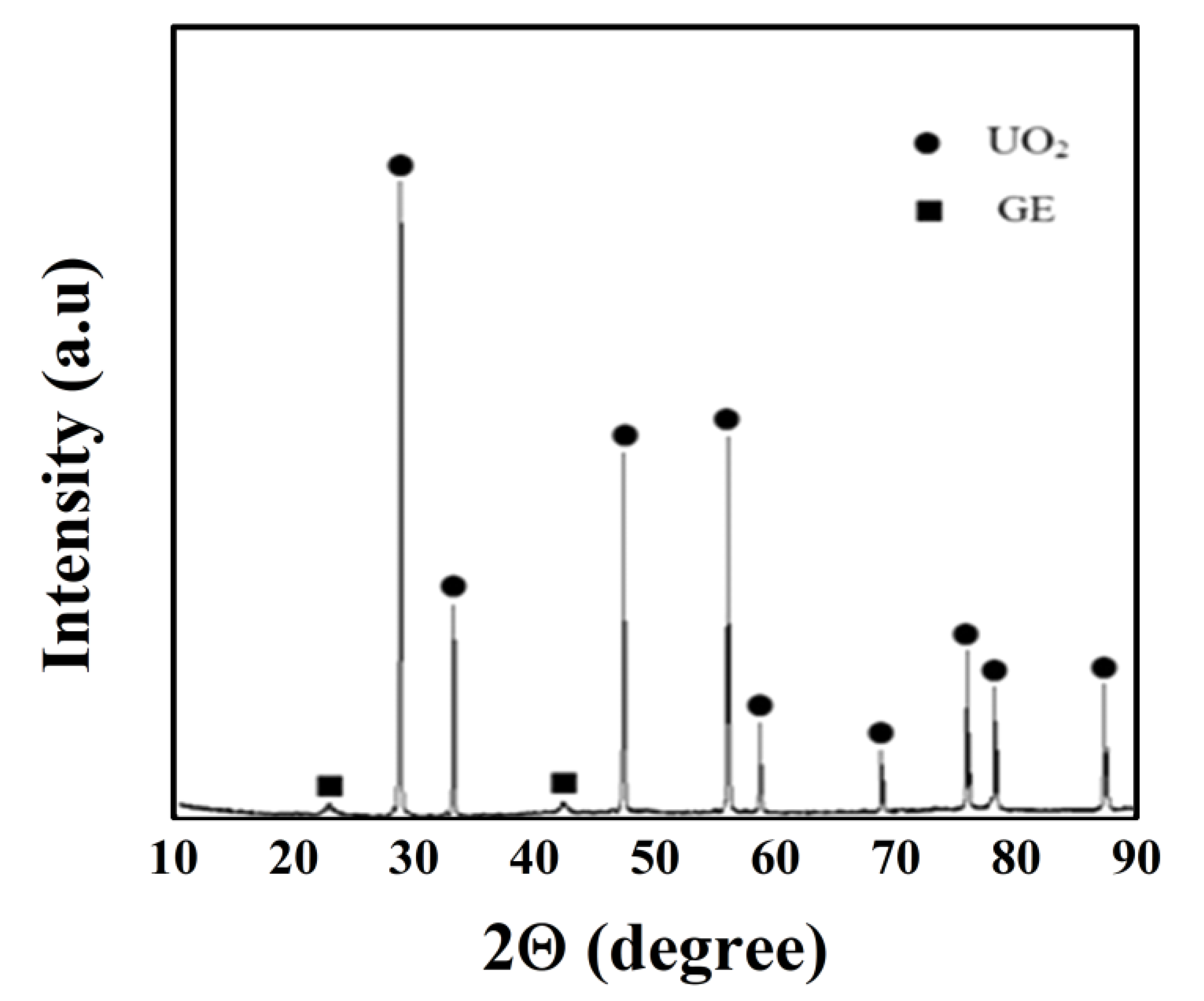
Figure 4 shows a phase structure comparison for sintered pellets. At 1723 K, the sintered pellets had two phases, that is, UO
2 and graphene phases. UO
2 did not react with graphene and graphene dispersed in the UO
2 matrix intact, and the second phase was protected [
16]. The XRD phase pattern was consistent with the DTA analysis results.
3.3. Factors Influencing the Density of UO2–Graphene Sintered Pellets
The density of UO
2–graphene sintered pellets was measured by drainage, as shown in
Table 2 and
Figure 5. With higher graphene content, the density of sintered pellets prepared by physical mixing and in situ synthesis both decreased. This was because the sintering densification of UO
2 was mainly achieved by atomic diffusion, and the doping of graphene prevented UO
2 from diffusing between atoms, which could have decreased the density of the sintered pellets [
17,
18].
However, the density of the sintered pellets prepared by physical mixing decreased more significantly. When the graphene content was 8%, the density decreased to 90.97%TD, which failed to meet the relevant requirement for reactor use (no less than 94%TD). The density decrease of sintered pellets prepared by in situ synthesis was very slow, and the density did not decrease significantly with added graphene. When the graphene content was 8%, the density was 94.96%TD, which met the relevant requirement for use in the reactor. The main reasons why in situ synthesis differed from physical mixing are as follows: for the UO2–graphene mixed powder prepared by in situ synthesis, graphene—as the nuclei for reactive deposition of UO2—made UO2 coat its surface fully and evenly so that UO2 bound to graphene at the molecular level. When sintering pellets prepared from this powder, the inter-particle contact was UO2, while the graphene was just a coating. This was conducive to the diffusion and densification of UO2 atoms at high temperatures and greatly offset the negative effect of graphene on pellet densification.
This experiment utilized spark plasma sintering (SPS) because it was difficult to densify the pellets by conventional pressureless sintering after UO2 was doped with graphene powder. Results showed that the density of sintered pellets obtained by pressureless sintering was <88%TD, which failed to meet relevant design requirements for nuclear fuel. An advantage of SPS lies in the rapid temperature rise for sintering. At the same time, pressurizing helped to densify the pellets. At a sintering time of less than 1 h, the pellet density did not meet relevant requirements. For example, at a sintering time of 30 min, the density of pellets doped with 2% graphene was 90.82%TD. Therefore, the sintering time for these experiments was 1 h.
3.4. Factors Influencing Thermal Conductivity of UO2–Graphene Sintered Pellets
For the thermal conductivities of UO
2–graphene sintered pellets, see
Table 3 and
Figure 6 and
Figure 7. The thermal conductivities of sintered pellets prepared by either physical mixing or in situ synthesis increased gradually with graphene, and the graphene improved the heat transfer capacity of the pellets. For sintered pellets with the same graphene content, the thermal conductivity of pellets prepared by in situ synthesis was relatively high for three reasons: first, for pellets prepared by in situ synthesis, graphene dispersed fully with a good mixing uniformity (as shown in
Table 1). The pellets with high graphene mixing uniformity were more likely to form a network bridge in the pellets, which was conducive to the outward transfer of pellet heat. Second, the UO
2–graphene interfacial binding properties for the pellets prepared by in situ synthesis were better than physical mixing; for the mixed powder prepared by a wet process, a contact at the molecular level may be achieved, which is conducive to interfacial bonding during sintering. Third, the sintering density for pellets prepared by in situ synthesis exceeded that of physical mixing (as shown in
Table 2), and the sintering density directly influenced the thermal conductivity of pellets. Therefore, the thermal conductivity of pellets prepared by in situ synthesis was relatively high. At room temperature, the thermal conductivities of sintered pellets doped with 2%, 4%, 6%, and 8% graphene prepared by in situ synthesis increased by 12.27%, 20.13%, 27.47, and 34.13% respectively.
This study also found that the increase rate for the thermal conductivity of pellets at 1273 K was higher than at 293 K because the thermal conductivity of UO2 decreased sharply at high temperatures, though graphene did not change much. At this point, graphene further advanced the thermal conductivity of the pellets due to its better thermal conductivity at higher temperatures. This could increase the safety and economic efficiency of the fuel in service at high temperatures and compensate for the low thermal conductivity of UO2 at high temperatures. Compared to physical mixing, in situ synthesis advanced the thermal conductivity of pellets at 1273 K, the graphene in the pellets was more evenly distributed, the interfacial contact was better, and the thermal conductivity of graphene was fully exerted.
3.5. Microstructure of UO2–Graphene Sintered Pellets
Figure 8 shows the microstructures of UO
2–graphene sintered pellets (graphene contents 8% and 4%) prepared by physical mixing and in situ synthesis. The pellets prepared by physical mixing showed more pores concentrated along the grain boundary due to lack of physically mixed pellets, as the UO
2 did not mix with the graphene powder evenly, which resulted in agglomeration. The agglomerated graphene concentrated at the grain boundary of UO
2 hindered the sintering densification of UO
2 pellets, which produced more pores, while pellets prepared by in situ synthesis did not show obvious pores at the grain boundary because the grains were closely bonded. This was due to graphene coating UO
2 during the preparation of the mixed powder, which bound at the molecular level. Such a mixed powder has two advantages: first, UO
2 evenly mixes with graphene without the agglomeration of graphene. Second, during sintering, homogenous substances between UO
2 particles bound directly and increased the sintering density. Graphene was uniformly coated by UO
2, and the thermal conductivity of the pellets improved by forming a bridging heat conduction network [
19,
20].
4. Conclusions
The problem of uneven mixing of UO2 with graphene was solved by in situ synthesis. The in-situ synthesis method elevated the mixing uniformity of graphene powder to 96.39%, which provided an excellent mixed powder for subsequent pellet sintering.
In the sintered pellets at 1723 K, there were only phase structures of UO2 and graphene. Graphene was not destroyed during the reaction with UO2. The densities of pellets doped with 2%, 4%, 6%, and 8% graphene prepared by in situ synthesis were 95.56%TD, 95.32%TD, 95.08%TD, and 94.76%TD, respectively. The pellet density did not decrease significantly with increased graphene. The thermal conductivities of the pellets at 293 K increased by 12.27%, 20.13%, 27.47%, and 34.13%, respectively, and increased by 18.36%, 35.00%, 47.07%, and 58.93% at 1273 K, respectively. The performance of graphene in the fuel was better at high temperatures, which overcame the shortcomings due to the low thermal conductivity of UO2 at high temperatures.
The grain sizes of the pellets prepared by in situ synthesis were 10–30 μm, and there was no obvious pore at the grain boundary because the grains were closely bound. Graphene was coated by UO2 uniformly, and the thermal conductivity of the pellets improved by forming a bridging heat conduction network.


