Article

Nanocomposite-Based Electrode Structures for EEG Signal Acquisition

by
Ashok Vajravelu
1,*,
Muhammad Mahadi Bin Abdul Jamil
1,
Mohd Helmy Bin Abd Wahab
1,
Wan Suhaimizan Bin Wan Zaki
1,
Vibin Mammen Vinod
2,
Karthik Ramasamy Palanisamy
2 and
Gousineyah Nageswara Rao
1
1
Faculty of Electrical and Electronic Engineering, Universiti Tun Hussein Onn Malaysia, Batu Pahat 86400, Malaysia
2
Department of Electronics and Communication Engineering, Kongu Engineering College, Erode 638060, India
*
Author to whom correspondence should be addressed.
Crystals 2022, 12(11), 1526; https://doi.org/10.3390/cryst12111526
Submission received: 25 September 2022 / Revised: 20 October 2022 / Accepted: 21 October 2022 / Published: 27 October 2022
(This article belongs to the Special Issue Advances in Multifunctional Nanocomposites)

Abstract

:
Objective: To fabricate a lightweight, breathable, comfortable, and able to contour to the curvilinear body shape, electrodes built on a flexible substrate are a significant growth in wearable health monitoring. This research aims to create a GNP/FE electrode-based EEG signal acquisition system that is both efficient and inexpensive. Methodology: Three distinct electrode concentrations were developed for EEG signal acquisition, three distinct electrode concentrations (1.5:1.5, 2:1, and 3:0). The high strength-to-weight ratio to form the tribofilm in the fabrication of the electrode will provide good efficiency. The EEG signal is first subjected to a wavelet transform, which serves as a preliminary analysis. The use of biopotential signals in wearable systems as biofeedback or control commands is expected to substantially impact point-of-care health monitoring systems, rehabilitation devices, human–computer/machine interfaces (HCI/HMI), and brain–computer interfaces (BCIs). The graphene oxide (GO), glycerol (GL), and polyvinyl alcohol (PVA) GO/GL/PVA plastic electrodes were measured and compared to that of a commercially available electrode using the biopic equipment. The GO/GL/PVA plastic electrode was able to detect EEG signals satisfactorily after being used for two months, demonstrating good conductivity and lower noise than the commercial electrode. The GO/GL/PVA nanocomposite mixture was put into the electrode mold as soon as it was ready and then rapidly chilled. Results: The quality of an acquired EEG signal could be measured in several ways including by its error percentage, correlation coefficient, and signal-to-noise ratio (SNR). The fabricated electrode yield detection ranged from 0.81 kPa−1 % to 34.90 kPa−1%. The performance was estimated up to the response of 54 ms. Linear heating at the rate of 40 °C per minute was implemented on the sample ranges from 0 °C to 240 °C. During the sample electrode testing in EEG signal analysis, it obtained low impedance with a good quality of signal acquisition when compared to a conventional wet type of electrode. Conclusions: A large database was frequently built from all of the simulated signals in MATLAB code. Through the experiment, all of the required data were collected, checked against all other signals, and proven that they were accurate representations of the intended database. Evidence suggests that graphene nanoplatelets (GNP) hematite (FE2O3) polyvinylidene fluoride (PVDF) GNP/FE2O3@PVDF electrodes with a 3:0 concentration yielded the best outcomes.

1. Introduction

It is possible to control external devices with one’s brain activity, thanks to BCIs. Electroencephalography (EEG) is a noninvasive method of measuring cortical electrical activities that provides highly detailed temporal information reflecting the dynamics of brain activities [1,2] because of its portability, high mobility, simple setup, and low cost. By incorporating the nickel nitroprusside (NNP) nanoparticles with GNP/FE electrode fabrication, the efficiency is improved and the cost can be reduced [3], which is why it has seen extensive application in BCI studies [4,5]. Traditional Ag/AgCl electrodes bathed in the conductive gel are frequently used to collect trustworthy EEG data. When utilizing traditional gel electrodes, it may be time-consuming to prepare the electrodes and clean the cap at each electrode location after an experiment [6]. The conductive gel residues make the hair seem filthy and are a huge annoyance for consumers. Users must inject conductive gel at each electrode location to reduce the skin–electrode resistance and prevent a short circuit caused by the gel’s flow ability. Without the correct training, this technique might be tough [7]. Additionally, the drying effects of the conductive gel restrict the recording time [8].
Many new types of new electrodes have been developed to overcome the drawbacks of gel electrodes. The dry electrode is one type of electrode that can be used, and it can be made from various materials such as metal [9]. However, dry electrodes have a high skin–electrode impedance and cause motion abnormalities due to friction between the heads and electrode pins. Several methods have been proposed to decrease the skin–electrode impedance including water-based electrodes [10] and bristle-shaped semi-dry electrodes [11]. The contact impedance between wet and dry electrodes is lower, and the process is hygienic and gentle on the hair when using a saline or water solution for conduction. The contact impedance grows considerably with time due to the conductive fluid’s fast evaporation rate. However, it could facilitate the development of short circuits between neighboring electrodes [12]. Many effective stretchy electrodes have been developed alongside the rise in flexible electronics [13].
Conductive salt-containing ionic hydrogels are quickly gaining in popularity as a novel type of transparent, flexible material [14]. The soft ionic conductivity, low interfacial impedance, and strong wetting effects on the skin’s surface are all contributing factors to the hydrogel’s remarkable features [15]. Recent research into hydrogels for EEG signal recording has focused on materials such as cross-linked sodium polyacrylate gels inflated with electrolyte, AG602 hydrogel membranes [16], and polyacrylamide (PAAM) hydrogels [17]. These hydrogels serve as the conducting medium and are typically adhered directly to the skin. These hydrogels are too weak to break through hair; therefore, they can only be used on bald heads. An alginate-based hydrogel was proposed to address this issue. This hydrogel, injected as a viscous liquid into the scalp, hardens within minutes to facilitate speedier scalp cleansing. Unfortunately, the process of removing the alginate-based hydrogel from the user’s hair is notoriously painful. Due to the high gelation rate, users will need to make multiple batches of hydrogel for experiments requiring several electrode sites. No existing hydrogel electrodes, to the best of our knowledge, are suitable for acquiring high-quality EEG data on hairy scalps in a practical manner.
This paper presents a novel ionic hydrogel-based EEG electrode. The ionic hydrogel can be used in the place of conventional conductive gels to make skin-to-metal (Ag/AgCl) electrode contact. Because hydrogels are gels, they will not leave any marks on the scalp after the experiment is over. Electrode structures in the shape of claws and patches made from 3D-printed elements are intended to reduce the skin–electrode contact impedance. The claw-like electrode structure is designed to chop through the hair in dense areas. The contacting surfaces of the five claws are hemispherical hydrogel constructions extruded from the electrode container. The cylindrical hydrogel is sliced into tiny pieces and immediately glued to the Ag/AgCl electrode on the balding forehead [18].
The cylindrical hydrogel can be mass-produced and kept for up to 18 days. The real benefit of our design is that it is easy to prepare and store for practical use, unlike other hydrogel-based electrodes. Furthermore, the unique electrode designs provide pleasant and good skin–electrode contact. Commercial gel electrodes, dry electrodes, and water-based electrodes are employed as standards against which the performances of the ionic hydrogel electrodes can be judged. High electrical performance and low noise are characteristics of ionic-hydrogel electrodes [19]. As a result of the wetting effects and an increase in the contact area, the skin–electrode impedance is greatly reduced. Our new electrodes performed similarly to regular gel electrodes on the hairy scalp, as shown by EEG signal measurements and experiments using steady-state visual evoked potentials in a few patients [20]. With the support of the Fe–Mg oxide composite, homogeneous absorbent nanoparticles used with graphene nanoplates to improve the efficiency of electrodes [21]. To reduce the pollution through the electropolishing process of the material GNP/FE, the performance of the electrode can be improved [22]. High contact impedance as well as a low signal-to-noise ratio can be achieved using this GNP/Fe material while using the scalp electroencephalogram (EEG) recording [23].

2. Fabrication of Electrode Materials and Methods

2.1. Flexible Architectures for Printed Electrode Fabrication

The chemical composition, physical, and surface features of the materials used in flexible electrode manufacturing are different. Porous textiles are highly sought after as a substrate because of their adaptability, breathability, and comfort. Fibers, flexible, long polymeric structures with a high length-to-width ratio, are the first step in creating textile substrates. These fibers are too flat and lack sufficient mechanical strength to function as a standalone material.
Various functional groups exist in the chemical structures of naturally occurring fibers, each having a specific affinity for a certain chemical. As a result, picking the right conductive elements to add to natural fibers is essential. Unlike synthetic fibers, made up of continuous filaments, natural fibers such as cotton, wool, silk, and bamboo are produced as staple fibers from various plants, animals, and mineral sources (except silk). Staple length, chemical architecture, constituent polymer properties, and the fibers’ geometry and morphology all play significant roles in determining the fibers final characteristics [19].
Alternatively, synthetic fibers, also known as a filament, can have their chemical structure and reactivity modified to suit various purposes. Synthetic polymers have become widely available and inexpensive, which has led to a revolutionary increase in filament production and a resulting monopoly on the fiber market. After being made, filaments exist in a continuous state from which shorter staple lengths can be clipped as needed. To create yarns that are sufficiently robust, hundreds of strands and filaments are woven together continuously. Despite this, textile yarns are unique because their flexibility allows them to interlace, make loops, and unite with glue to form a two-dimensional planar structure known as fabric.
While single-and multi-stranded yarns and fibers are well-suited for interconnects, multi-and bi-stranded fabrics are often employed to cover huge areas. It is vital to bear in mind that not all printing methods are compatible with flat textile designs. Despite the increasing attention paid to 3D-printed fibers and textile structures [20], these technologies are still in the experimental stages and often fail to replicate the qualities of traditional textiles. Nonwoven may be isotropic among the planar fabric structures, in contrast to the highly anisotropic woven and knit fabric. Nonwoven fabric’s isotropic properties are a function of the fabrication process, allowing for precise control over the fiber orientations.
Nonwoven fabrics enable finer surface roughness, porosity, and thickness control than any other fabric category. Although nonwoven fabrics are more aesthetically pleasing than knit or woven options, its lack of drape, elasticity, and breathability precludes its use for continuous health monitoring over extended periods. In contrast, the surface and physical properties of woven and knit textiles undergo modest but visible changes due to multiple offshoots. Knit materials are more flexible and breathable than other textiles, making them ideal for clothing; however, their porous structure makes them difficult to print on inkjet printers. The contact resistance between strands in knitted fabric is increased by the intermittent contact between them, making it more difficult to fabricate electrodes with adequate electrical conductivity. However, incorporating sufficient electrical conductivity into knitted fabric may be useful for extremely stretchable strain and pressure sensing for wearable applications [24]. Weaved cloth has a more stable dimension and less elasticity than knit fabric, making it a more durable printing surface to fabricate electrodes on textile substrates, however, it is necessary to overcome a distinct set of problems than those encountered when working with flat thin film substrates.
Controlling the conductive pattern when printing with conductive pastes or inks is challenging because they readily permeate the fiber interstices of planar fabric. To avoid this issue, conductive layers must be printed before high surface energy interface layers. Substrates made of natural fibers, synthetic fibers, or a combination of the two, or their blend, have been widely used as printing electrode substrates. While nonwoven fabrics were once utilized as a substrate to fabricate wearable electrodes, woven and knitted fabrics have now taken their place. It is possible to modify the conductivity of printed traces on textile surfaces for specific uses by adjusting the fiber diameter.
Making devices out of fabric requires careful consideration of several elements. One of humanity’s most necessary materials, textile, is subjected to rigorous manipulation such as folding, stretching, and rubbing. To provide the necessary close touch with the body and mechanical stability, the textile devices must be designed with careful attention to their morphological and structural details. High-performance sensors provide a quick response and quick recovery. Depending on the transduction mechanism, extremely sensitive sensors convert mechanical stress or strain into electrical signals. To guarantee accurate signal capture, certain applications need sensors capable of self-healing. This is especially important when the device is subjected to repetitive stress or strain. Another important condition is that the signal response is linear; nonlinear responses and drifts in response can complicate the calibration procedure.
To obtain clean readings from electrochemical sensors, collecting biomarkers for analyses with care is important [25]. An incorrect response from the sensor is possible if analyses from the previous sample have accumulated on the electrode surface. Reusability in analytical use may be ensured by a well-designed microfluidics system and the sensor’s potential to self-clean. Because fabric devices are worn so close to the skin, biocompatibility is important to consider to prevent irritation or harm. Self-powering capabilities are being researched to reduce the devices’ need for cumbersome and fixed parts. Triboelectric nanogenerators (TENGs), thermoelectric generators (TEGs), bacterial fuel cells (FCs), and photovoltaic (PV) textiles, among others, are now being studied as potential sources of power for self-powered fabric devices. Studying these characteristics may lead to flexible fabric devices that function as well as or better than their rigid counterparts when used with common household goods [26].

2.2. Nanomaterials for Conductive Ink Formulation

Material selection for active electrode manufacturing directly impacts how well the flexible electrodes work. The substance must increase the substrate’s electrical conductivity while preserving its flexibility and mechanical qualities. The conductive layer also needs to withstand unfavorable external phenomena such as washing, abrasion, perspiration, and constant mechanical deformations, in addition to being environmentally stable. Metal-based nanoparticles, carbon-based, and conductive polymers are the three main types of nanomaterials employed in the manufacture of conductive electrodes. MXene has increased rapidly in recent years due to its better conductivity, dispensability, and environmental stability in flexible electronics.
The use of metal in producing flexible textile electrodes has received much attention during the past two decades. Zero-dimensional nanoparticles (NPs) and one-dimensional nanowires (NWs) of bulk metals are examples of conductive metal nanomaterials. Copper (Cu), gold (Au), and silver (Ag) are some of the most commonly used metals in functional applications (Ag). Although gold nanoparticles (Au NPs) are corrosion and oxidation resistant and have a conductivity equivalent to silver nanomaterials, they are more expensive and difficult to produce due to their rarity and the need for a high temperature and vacuum during deposition [27].
Creating a surface oxide layer during synthesis in the atmosphere contributes to the thermodynamic instability of Cu NPs, which is one difficulty. One obstacle that has yet to be conquered is maintaining the stability of conductive nanostructures based on metals. In addition, a sintering procedure is necessary for the surface deposition of metallic nanoparticles. To create a uniform thin layer over the substrate, sintering removes the carrier solution from the liquid phase. In addition, nanoparticles frequently create issues during inkjet printing due to the coffee ring effect, wherein nanomaterials aggregate along the periphery of a circular droplet. There is a wide range of nanomaterial dimensions present in carbon-based nanomaterials, from the two-dimensional graphene to the zero and 1D carbon quantum dots (CQDs) and carbon nanotubes (CNTs). Carbonaceous nanoparticles are highly sought after in materials science because of their improved mechanical strength and resistance to environmental degradation [28].
The use of graphene and CNTs in printable functional ink is actively being researched. It is a single sheet of carbon atoms arranged in a 2D structure. As a result of its outstanding electrical and mechanical qualities, it is viewed as a potentially game-changing material for flexible electronics. Graphene oxide (GO), which contains oxygen, is typically employed for the dispersion manufacture of liquid phase ink because of graphene’s lack of functional groups. However, this dispensability comes at the expense of electrical conductivity; hence GO cannot be employed in producing conductive electrodes. The electrodes’ functioning depends on the degree to which the GO is reduced to generate reduced graphene oxide (rGO) [29]. The characteristics of CNTs such as whether they are semiconducting or metallic are determined by the chirality of the graphene sheets along their length. CNTs have a conductivity that is on par with metal, but their resistance is higher due to flaws introduced during production. There is strong adhesion between the CNTs and the textiles.
However, CNTs present several difficulties that must be overcome throughout the printing process. Huge bundles of CNTs form due to their large aspect ratio, which leads to nozzle clogging. The electrical properties of metals can be mimicked in organic compounds called “intrinsically conductive polymers” (CPs). For a charge to be transported through a polymer chain, a delocalized p-electron or conjugation is essential. Popular CPs such as polypyrrole (PPy), polyaniline (PANI), poly(3,4-ethylene dioxythiophene) (PEDOT), poly-acetylene (PA), and polythiophene (PT) are appealing due to their excellent electrical flexibility, and low weight. When it comes to printed textile electrodes, PEDOT is a popular choice. Despite being exposed to humidity and extreme temperatures, PEDOT maintains its electrical conductivity and stability. Doping PEDOT with a polyanion such as poly-styrene-sulfonate (PSS) makes it water-dispersible and improves its film-forming capabilities.

2.3. Inkjet Printing

Inkjet printing is a solution-based functional material patterning technology because it deposits nanomaterials in the form of a colloidal dispersion on the substrate. The system generates droplets, spreads the ink, and dries them to create patterns on the surfaces. This process begins with digital design preparation. Because it does not require a mask, it is suitable for both pressure-sensitive and non-planar substrates. Continuous inkjet (CIJ) and drop-on-demand (DoD) are the two operational modes that can be used to deposit the ink droplets. An electrical discharge between electrodes causes the nozzle of a continuous inkjet (CIJ) printer to continuously emit pressure ink, which is subsequently broken up into uniform droplets by surface tension.
However, the DoD system only produces a single drop upon activation. DoD is differentiated by its tiny droplet diameter, great precision, and enhanced print quality. The CIJ technique is widely used in the industrial industry, while the DoD approach is the gold standard for cutting-edge printing materials. Double-shot inkjet printing and reactive inkjet printing are two examples of recent inkjet printing advancements using systems with multiple nozzles. To control the quality of the printed pattern, inkjet printing requires careful evaluation of several parameters. To minimize the creation of satellite droplets and achieve good pattern printing, for instance, the nozzle’s distance from the substrate must be optimized. To avoid gaps in patterns and the clustering of particles due to fluctuations in the distance, the spacing between drops should be optimized. Different approaches are suggested to counteract the coffee ring effect resulting from unequal evaporation across a droplet. However, the ink system imposes several limits including the price and the requirement of high-temperature curing, making ink engineering a crucial part of employing this method for printing on textile substrates. Recently developed ink based on 2D materials has shown remarkable compatibility with inkjet printing on a wide range of textile substrates.
Over the past decade, inkjet printing has garnered a lot of interest as a means of making flexible and wearable electrodes. Inkjet printing on a textile substrate has been used for many wearable applications. Biochemical sensing gloves printed with bioactive silk ink by Tao et al. inkjet’s printing technique were developed in 2015. It is possible to create a novel “silk ink” formulation by adding other functional components to the ink such as dopants and bioactive chemicals without compromising the ink’s compatibility with the inkjet printing process. Neither organic nor inorganic solvents are needed because the ink is made in an aqueous system. After treating the cotton fabric with a hydroxyl functional polystyrene emulsion polymer, Karim and his team used an inkjet printer to print graphene-based ink onto the material. The pre-treatment guaranteed a continuous, consistent print. In terms of sheet resistance, the fabric experienced a reduction of three orders of magnitude.
Not only is GO/GL/PVA conductive in solid form, but it also possesses higher signal accuracy and lower noise than the Ag/AgCl electrode and even GO/PEG/PVA. It is compatible and reusable because of this. As a result of the combined efforts of the composite ink, the sheet resistance was reduced to 2.11 X. After in situ heat curing was applied, two orders of magnitude reduced the sheet resistance. When the ink droplet size exceeded the fiber diameter, the ink tended to pool at the junction rather than spread out. However, when heated, the ink morphed into a mesh-like structure, and a continuous conductive line resulted. This solves a major issue with inkjet printing not encountered with ink containing silver nanoparticles: nozzle clogging. Furthermore, after 10,000 bending cycles, the ink on the knit fabric showed no substantial increase in resistance.
The process’s viability was also investigated, along with the retention of natural flexibility, breathability, and comfort. Combining inkjet printing with silver ink offered an innovative strategy for addressing the mechanical incompatibilities between the textile substrate and the ink. This process reduced the electrode’s elastic modulus and increased its stretchability, resulting in a more forgiving mechanical response. The enhanced electromechanical performance of the textile patch was achieved through the alignment of the conductive element and wearable platform and the prevention of crack formation during stretching. Modifying the patterned cut-out ratio also allows for individualized electromechanical properties. Textiles with low glass transition temperatures need to be printed using low-temperature inkjet technology to prevent the substrate from becoming brittle during printing. Water-soluble silver ink was developed using a modified version of the Tollens’ process. The textile surface could be an inkjet printer while concurrently sintering at low temperatures of about 90 Celsius. A layer of acrylic copolymer-based resin served as an interface and onto which was printed ink.
Inkjet-printed silver ink was shown to be more resistant to sensor bending than lithography. Inkjet printing is an inkjet used to produce a fluor elastomer nanocomposite ink containing silver particles onto polyurethane (PU) nanotextile substrates. By controlling the ink penetration to create a cladding layer, the mechanical and electrical characteristics of the electrode were improved. The two processes generally necessary to print with silver inks—pre-treatment and high-temperature post-treatment—are eliminated, saving time. Inkjet printing produces higher-resolution prints while using less viscous ink than traditional screen printing. Printing on textiles using a low-viscosity inkjet printer provides more exact control over individual print regions. It makes preserving the fabric’s inherent properties easier. While particle-free ink would prevent nozzle clogging, it would limit the usefulness and adaptability of inkjet printing on a range of textile surfaces.
In contrast to particle-free ink, particle-based inks are available and may be used with a broader range of textile substrates as well as being less expensive. The requirement to adapt ink chemistry for diverse substrates to obtain optimal performance limits one’s capacity to print on textiles. Screen printing is more suited to huge production runs than inkjet printing. The processes described above generate two-dimensional prints on a variety of substrates, with the majority of prints filling the substrate’s top layer. This makes regulating the ink’s diffusion inside multilayer substrates difficult, thus limiting the complexity and breadth of electrodes that may be created.
Biopotential monitoring: The electrocardiogram (ECG), electroencephalogram (EEG), electromyogram (EMG), and electrooculogram (EOG) are all common biopotentials that function by sensing changes in electrical potential. Monitoring these biopotentials using wearable textile-based electrodes can significantly reduce clinical visits and costs. Data obtained from signal collecting and processing are vital to the health care business since they are employed in patient diagnosis and monitoring. The major technique of collecting biopotential signals is through physical sensors. A wide range of transduction mechanisms including piezoresistive, piezoelectric, and capacitive approaches are used to acquire data. Because of the deposition of nanomaterials on the substrate during stress, the effective mass of charge carriers and the distribution of active materials change, causing a change in the resistance of the piezoresistive sensors. Piezoelectric sensors use the reorganization of crystal structures to turn mechanical energy into electrical signals. The potential difference between two points in a material changes in a way that is proportionate to the stress exerted. Typically, a capacitive sensor consists of two electrodes separated by a small distance, with the distance between them being the dielectric. When the distance between the electrodes is altered due to deformation, the capacitance changes and a corresponding signal is generated. With a good error percentage, correlation coefficient, and signal-to-noise ratio, the manufactured electrode with the ratio combination performs well in signal acquisition (SNR). The skin contact impedance ranges from 50 KΩ cm2 at 10 Hz, and the electrodes can also acquire alpha signals in the EEG, even in dense hair heads. The novelty of this work is as follows: adding glycerol and PVA in the electrode fabrication using GO is novel, and gave a good performance in the aspects of error percentage, correlation coefficient, and signal-to-noise ratio (SNR) [30]. PVA is used due to its strengthening property, which gives additional support to the electrode [31]. Glycerol will increase the electrode flexibility, and conductivity, and the electrode can be used without the wetting process [32]. With the support of a Fe–Mg oxide composite, the homogeneous absorbent nanoparticles were used with graphene nanoplates to improve the efficiency of electrodes. To reduce pollution through the electropolishing process of the material GNP/FE, the performance of the electrode can be improved [33]. High contact impedance as well as low signal-to-noise ratio can be achieved using this GNP/Fe material while using in scalp electroencephalogram (EEG) recording. The combination of nickel nitroprusside (NNP) with graphene nanoplatelet fabrication yields good performance when compared to other materials [34]. Due to the electrical conductivity and thermal and mechanical properties, it was proven to be superior to other electrode materials [35].

3. Methodology

The proposed block diagram is the result of the signal-sensing process used by the Myoware muscle sensor (Surface Electrodes). The surface area measurements are very important for active electrodes in super capacitor applications [36]. An Arduino UNO will receive the signal and transmit the data it collects to a laptop computer, where it may be seen and stored and later analyzed using MATLAB.

3.1. Connecting the Arduino UNO to the Myoware Muscle Sensor

The Myoware Muscle Sensor is connected to the Arduino. The connection between the components is depicted schematically below. Connect the ground pin of the sensor to the Arduino’s GND and the power pin to the 5V supply. It should link the analogue pin to the Arduino’s pin A0 since it watched the analogue voltage. It is straightforward to connect an EEG muscle sensor to an Arduino using Myoware. All that is required is an analogue voltage measurement. Once the code has been uploaded, the sensor may be tested and the value observed. An experiment was conducted with a stretch to see how sensitive the sensor was. As desired, the muscle can be constricted or released. On the serial monitor, the resultant analogue voltage could be seen. The generated analogue voltage was kept for future use.

3.2. Pre-Processing

The most important data from the EEG signal has been retrieved by employing wavelet transform (WT) as a practical method. Compared to other methods, wavelet analysis for analyzing EEG signals offers some advantages. The most notable benefit of utilizing a wavelet is the ability to offer time and frequency information about the signal and to concurrently analyze the EEG signal in the time–frequency domain.
Extraction of features via wavelet decomposition: A wavelet transform is an effective tool for processing biological signals. WT provides a scale that can be used to quantify signals. As a result, it is conceivable that separate frequency components of the signal and time information will be picked up simultaneously.
It is denoted that the wavelet function as (t) is the scaling function as s, where it could be written as the WT form
X   m , n = 1 n x t ψ t m n d t
If s > 1, the wavelet widens;
If s < 1, the wavelet diminishes.
Electroencephalographic waves of the Mat type of every wavelet function were managed by MATLAB’s specialized “wave menu” command.
For all simulations, we used one-dimensional wavelets. We initially input the signal into MATLAB, and then simulated it. Results from the software tool were compared to those obtained from the MATLAB code written to achieve the same goals. After installing MATLAB, it was used to organize a quantitative summary of the signal and provide a rationale for the total number of samples. We also had prior knowledge of the fact that the above signal’s duration constituted a crucial foundation.

3.3. Feature Analysis of EEG Signal

Because WT breaks signals into multiple scales, the raw signal captured using Myoware is sent to the wavelet analyzer tool of MATLAB. The software’s “sym2” method was chosen from among its numerous provided options. The level 4 Wavelet Transform sym2 preprocessed signal’s output is displayed below. In this study, it collected the EEG data from participants aged 10 and under, 10 to 20, 40 to 60, and 60 and over. Each age group’s EEG signal was recorded with Ag/AgCl electrodes and either a 1.5:1.5, 2:1 or 3:0 concentration of GNP/FE2O3@PVDF. Using GNP/FE2O3@PVDF electrodes of varying concentrations and AgCl, performance feature analysis was conducted by determining the percentage of error, the signal-to-noise ratio, and the correlation coefficient of the EEG signal.

3.3.1. Error Percentage

An error percentage is the proportional representation of the difference between an established or known value and an observed or experimental value, given as a fraction of the established or known value multiplied by 100%.

3.3.2. SNR (Signal-to-Noise Ratio)

The signal-to-noise ratio (SNR) evaluates how strong the desired signal is concerning the background noise. The ratio of signal-to-noise (S/N) can be calculated using a standard formula by first comparing two levels and then returning the result as a fraction. Checking this ratio can advise as to whether the noise is interfering with the signal of interest. The signal-to-noise ratio (SNR) is given in decibels by the formula r = SNR(x,y), where x is the magnitude of the signal and y is the magnitude of the noise.

3.3.3. Correlation Co-Efficient

The correlation coefficient represents the magnitude of the linear relationship between two independent variables (a and b). The linear correlation coefficient must be greater than zero for a relationship to be considered positive. A negative correlation is represented by a value below zero. In conclusion, a null connection exists between the two variables.

3.4. Experimental Details

3.4.1. Chemicals and Reagents

Graphite powder (99.9 per cent purity), sodium nitrate (NaNO3), hydrogen peroxide (30 per cent, H2O2), hydrochloric acid (37 per cent), potassium permanganate (KMnO4), sulfuric acid (95 to 97 per cent), polyvinyl alcohol (PVA), and diethylene glycol (DG; ROCH2CH2OCH2CH2OH, 97–96) are some of the chemicals used. The material combination for the fabrication of the electrode is a Ni foam substrate under the synthesis of chemical vapor with electrolyte 3 M KOH, which gave a capacitance of 741 F g−1 with a stability of 92.3% for 5000 cycles [37,38].

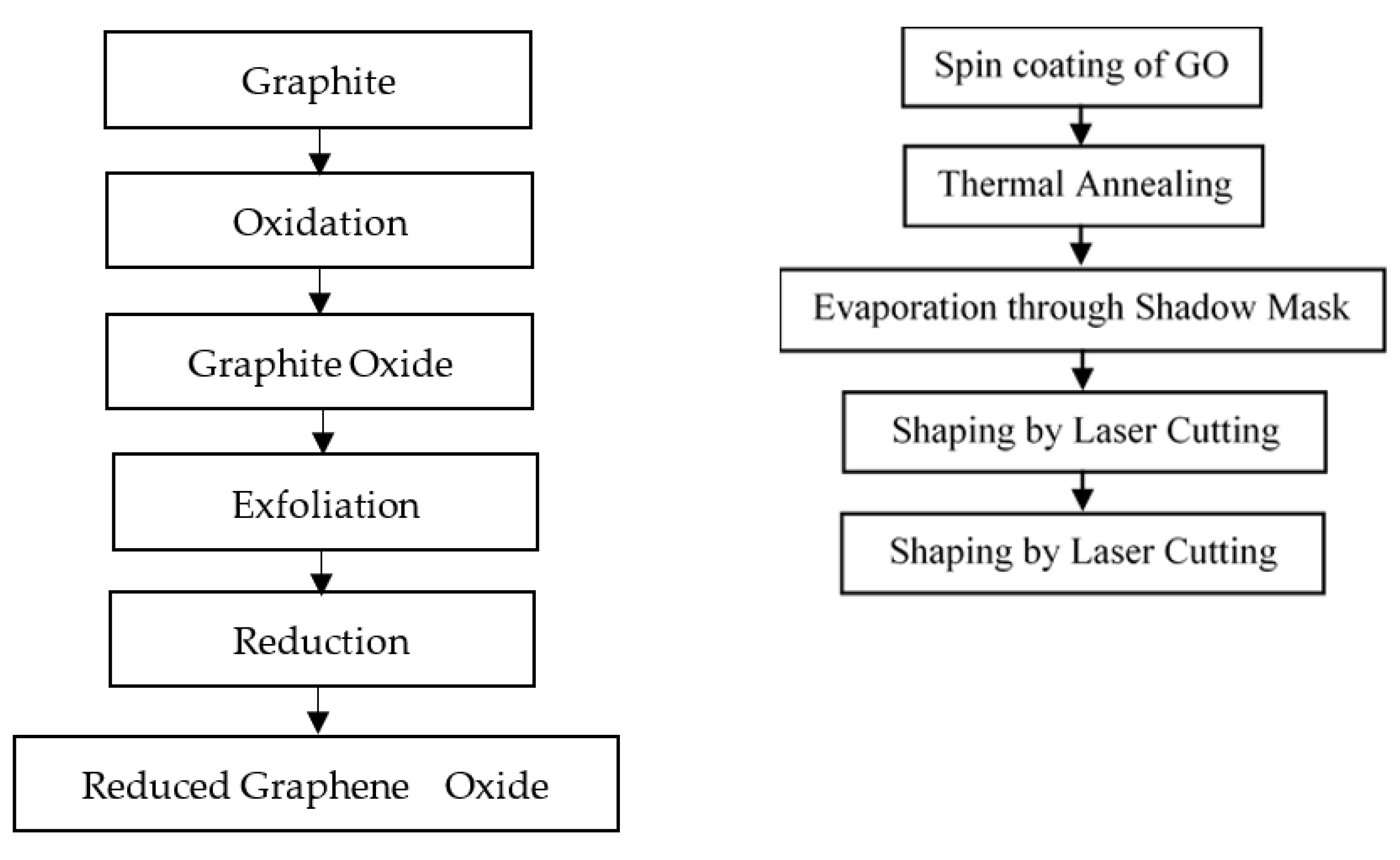
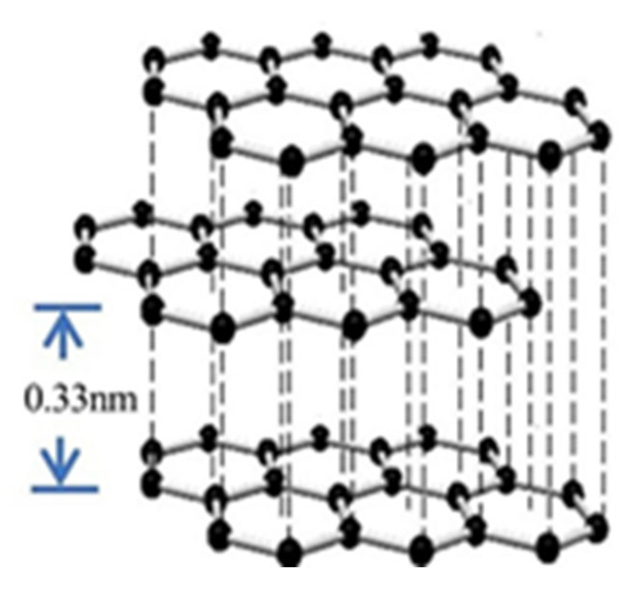
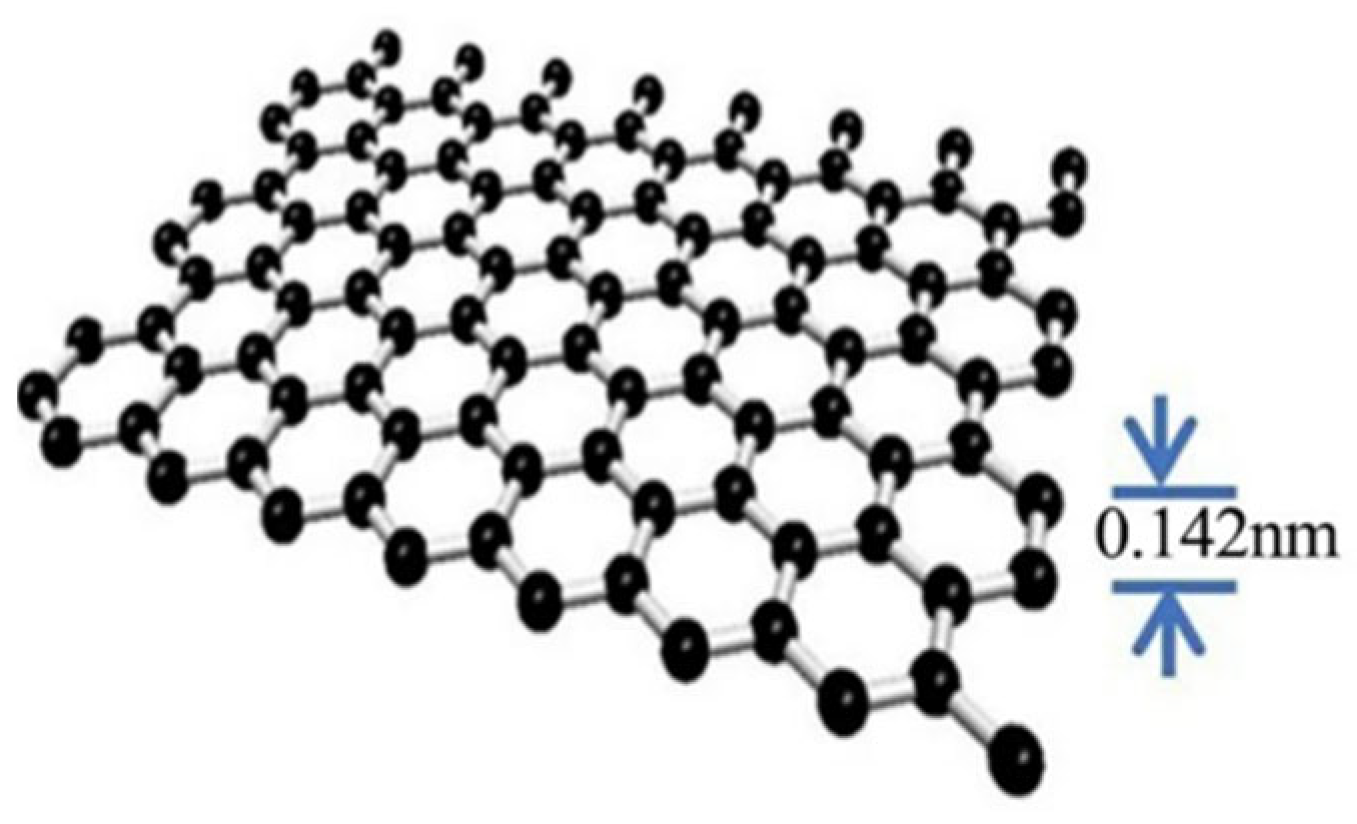
3.4.2. Synthesis of GO

The GO was made using a variation on the Hummer process. In an ice bath, graphite-concentrated sulfuric acid (H2SO4), and sodium nitrate (NaNO3) were first mixed together. To produce graphite oxide, potassium permanganate was gently added at a temperature of fewer than 35 °C. The paste becomes a brownish-grey color after sitting for a day. Once the temperature reached 90 °C, distilled water was added gradually. After that, the solution was distilled using distilled water and hydrogen peroxide to eliminate any remaining manganese ions. The precipitate was then centrifuged after being rinsed with distilled water. After being washed, the solid was dried for further use.

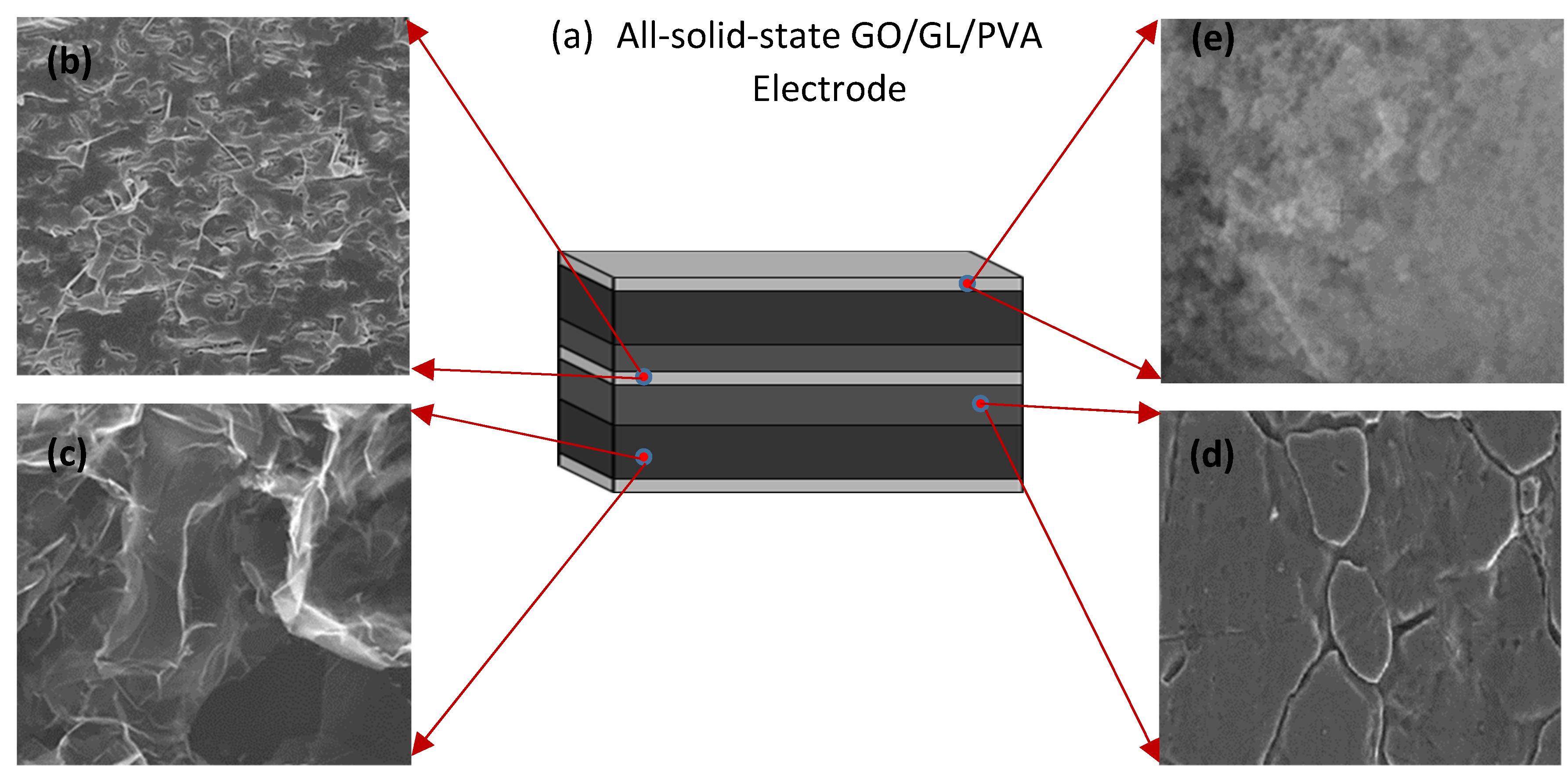
3.4.3. Preparation of GO/GL/PVA Composite Electrode

In the first stage of making GO/polymer composites, the GO was dissolved in water and the two components were mixed physically. Meanwhile, a 5 wt% PVA solution was made by dissolving PVA in deionized water. This was carried out in a water bath at 80 °C for 2 h while being gently agitated with a magnetic stirrer. There were three different dilutions of the GO/GL/PVA composite with deionized water (50 mL each): 1:20, 1:10, and 1:5. The high strength-to-weight ratio to form the tribofilm in the fabrication of the electrode will provide good efficiency. First, the GO and water were well combined while stirring. After being combined, the ingredients were cooked for 2 h at a low simmer, reaching 80 °C. To facilitate PVA dissolution in the water/GO solution, it was introduced very slowly and in small increments during heating. The next step was a quick cooling of the mixture to stop the GO from settling. The solidified electrode was then transferred to the electrode mold. When applying an electrode to human skin, it is necessary to first moisten the skin. Two days were spent in the desiccator with the electrode in its container. When completed, it can be popped out of the mold and used as an electrode in any container. Figure 1 depicts the solid GO/GL/PVA electrode, which may be reused frequently by simply wetting the skin. Compared to the disposable electrode, it has a higher level of activity. The electrocardiogram and electroencephalogram both used the same electrode (EEG). Figure 2 displays the overall fabrication of the electrode.

3.4.4. Application of the Sensor in Sensing Human Activities

The bio-back device was used to examine the GO/GL/PVA composite electrode and compare it to a silver/silver chloride electrode in the same conditions and on the same person. Numerous metrics including resting heart rate, peak-to-peak value, noise level, brain waves at the resting state, alert state, and in sedation condition were used in this analysis. The thickness of the fabricated electrode using graphene, the bond between the carbon–carbon, had a distance of about 0.142 nm, in addition to the layer height, which was about 0.33 nm. Figure 3 shows the schematic diagram of graphite. Similarly, Figure 4 shows the schematic diagram of single graphene from graphite.
Graphene layers were obtained using scanning electron microscopy, as shown in Figure 5. Furthermore, the graphene layers using high-resolution microscopy are shown in Figure 6.

4. Results and Discussion

The standard EEG signal was compared to the EEG signal recorded using the specified circuit and Ag/AgCl electrodes. Measurements of the two signals’ correlation coefficient, signal-to-noise ratio, and error percentage were taken under these conditions. The results of the calculations for the parameters are as follows: error percentage = 1.3348; SNR = 7.3744; correlation coefficient = 1. It can be concluded that the circuit is right because the percentage of errors was less than 2%, the signal-to-noise ratio was more than 0, and the correlation coefficient was greater than 1. Table 1 shows the findings of an evaluation of the performance of three concentrations of GNP/FE2O3@PVDF electrodes across ages below 10, Table 2 shows the age group of the 20s, and similarly, Table 3 in the age range of the 40s and finally, Table 4 under the age ranges from the 60s, respectively.
Calculations for the performance parameters were as follows: error percentage = 1.3348; SNR = 7.3744; correlation coefficient = 1. It can be concluded that the fabricated electrode was good because the percentage of errors was less than 2%, the signal-to-noise ratio was more than 0, and the correlation coefficient was greater than 1.

EEG Signal

The EEG is a form of electrophysiological monitoring that can be used to capture the brain’s electrical activity. The GO/GL/PVA composite electrode provided a strong EEG signal with minimal background noise. That is to say, the GO/GL/PVA composite electrode can also be employed for EEG analysis. Figure 7 displays the testing performance of the EEG signal acquisition.
The fabricated electrode yield detection ranged from 0.81 kPa−1% to 34.90 kPa−1%. The performance was estimated up to the response of 54 ms. The characterization of the fabricated electrode before sampling was conducted in real-time from an engineering perspective, and the fabricated electrode was tested in various systems as follows. With the help of micro-Raman spectroscopy, the fabricated material was exposed to the wavelength of 632.8 nm. With the casting powder dispersion techniques, the samples were separated and dried under ambient temperature. Linear heating at the rate of 40 °C per minute was implemented on the sample ranges from 0 °C to 240 °C. During sample electrode testing in the EEG signal analysis, low impedance was obtained with good quality of signal acquisition when compared to a conventional wet type of electrodes. The above performance was achieved due to the micropillar type of fabrication with a conductive base of 15 mm in diameter with 12 mm soft pillars. The dimension of the soft pillar structure was 1 mm in diameter, 2 mm in height, and 10 mm in pitch. The performance compared to the conventional electrode is displayed in Figure 8. These results were obtained during visually evoked potential.

5. Conclusions

Several identifying characteristics are used to classify EEG data. Ten samples of EEG signals were acquired from healthy persons across three age groups using three different doses of GNP/FE2O3@PVDF electrodes. Each sample was subjected to an algorithm, which allowed for the accurate determination of each variable. A large database was usually created by combining all of the simulated signals in MATLAB code. In this work, all of the needed data were gathered, tested against all other signals, and confirmed to be an exact depiction of the desired database. Evidence shows that a 3:0 concentration of GNP/FE2O3@PVDF electrodes produced the greatest results. The purpose of this study was to create a GO-based test electrode that may replace the present standard in a more practical and uncomplicated manner. The use of a GO/GL/PVA plastic electrode in an EEG has not been previously reported and neither has its preparation. The electrode fabrication process was simplified. The characterization also revealed that GO had diffused over the PVA and that two peaks in both GO and PVA had disappeared. Because it is long-lasting, user-friendly, and has an antibacterial sensor, it is useful for electrocardiogram, electrooculogram, and electroencephalogram examinations. Not only is GO/GL/PVA conductive in solid form, but it also possesses higher signal accuracy and lower noise than the Ag/AgCl electrode and even GO/PEG/PVA, which makes it compatible and reusable. It can be implemented in any system where a lateral current distribution is required. On top of that, unlike regular hydrogels, which are only good for one usage, it is not corrosive. The fabricated electrode yield detection ranged from 0.81 kPa−1% to 34.90 kPa−1%. The performance was estimated up to the response of 54 ms.
Challenges and future perspectives: This technology’s sixth difficulty is powering printed electrodes for long-term and continuous monitoring. Despite substantial advancements in electrode functionality over the past decade, self-powered electrode design is just starting. The gadgets’ portability and convenience are drastically diminished by the need to connect to an external power source. For this reason, energy-efficient technologies such as Bluetooth Low Energy (BLE) are recommended. In addition, extra effort can be spent developing and/or tuning a suitable algorithm to analyze raw sensor data before giving it to the user. Several nanogenerators including piezoelectric, pyroelectric, and thermoelectric ones have recently been discovered to have promising applications as energy harvesters that might be combined with wearable sensors to produce significant powers. However, before integrating them with wearable sensors, it is important to assess the efficiency of these nanogenerators. These issues and concerns must be resolved in future works before printing technology may be widely used to manufacture electrodes for medical applications.

Author Contributions

Methodology, K.R.P.; software, V.M.V.; writing—original draft preparation, A.V.; writing—review and editing, M.M.B.A.J., M.H.B.A.W., W.S.B.W.Z. and G.N.R. All authors have read and agreed to the published version of the manuscript.

Funding

TIER 1 H764 research grant from Research Management Centre (RMC) of Universiti Tun Hussein Onn Malaysia, Parit Raja, Batu Pahat, Malayisa.

Institutional Review Board Statement

Not applicable.

Informed Consent Statement

Not applicable.

Data Availability Statement

Not applicable.

Acknowledgments

The authors wish to thank the Research Management Center (RMC) of Universiti Tun Hussein Onn Malaysia for supporting this work through the TIER H764 research grant. The authors would also like to thank and appreciate the Management, Administrative Officials of Universiti Tun Hussein Onn Malaysia [UTHM], Malaysia, Kongu Engineering College [KEC], India, National Institute for Empowerment of Persons with Multiple Disabilities (Divyangjan) [NIEPMD], Chennai, India for their support in carrying out the research work successfully.

Conflicts of Interest

The authors declare no conflict of interest.

References

  1. Vajravelu, A.; Jamil, M.M.B.A.; Zaki, W.S.B.W.; Govindasamy, M. Survey and Analysis of Preprocessing Of EEG Signal. Ann. Rom. Soc. Cell Biol. 2021, 25, 2461–2488. Available online: https://www.annalsofrscb.ro/index.php/journal/article/view/5861/4523 (accessed on 21 August 2022).
  2. Christodoulides, P.; Miltiadous, A.; Tzimourta, K.D.; Peschos, D.; Ntritsos, G.; Zakopoulou, V.; Giannakeas, N.; Astrakas, L.G.; Tsipouras, M.G.; Tsamis, K.I.; et al. Classification of EEG signals from young adults with dyslexia combining a Brain Computer Interface device and an Interactive Linguistic Software Tool. Biomed. Signal Process. Control 2022, 76, 103646. [Google Scholar] [CrossRef]
  3. Rahman, M.M. Low-Cost and Efficient Nickel Nitroprusside/Graphene Nanohybrid Electrocatalysts as Counter Electrodes for Dye-Sensitized Solar Cells. Materials 2021, 14, 6563. [Google Scholar] [CrossRef] [PubMed]
  4. Choi, W.S.; Yeom, H.G. Studies to Overcome Brain–Computer Interface Challenges. Appl. Sci. 2022, 12, 2598. [Google Scholar] [CrossRef]
  5. Ashok, V.; Karthik, R.P.; Keerthana, K.M.; Roshinee, A.R. The survival of intellectual disabled subjects in social environment using BCI. In Proceedings of the 2018 International Conference on Intelligent Computing and Communication for Smart World (I2C2SW), Erode, India, 14–15 December 2018; pp. 181–184. [Google Scholar] [CrossRef]
  6. Liu, J.; Lin, S.; Li, W.; Zhao, Y.; Liu, D.; He, Z.; Wang, D.; Lei, M.; Hong, B.; Wu, H. Ten-hour stable noninvasive brain-computer interface realized by semidry hydrogel-based electrodes. Research 2022, 2022, 9830457. [Google Scholar] [CrossRef] [PubMed]
  7. Goyal, K.; Borkholder, D.A.; Day, S.W. A biomimetic skin phantom for characterizing wearable electrodes in the low-frequency regime. Sens. Actuators A Phys. 2022, 340, 113513. [Google Scholar] [CrossRef]
  8. Saha, T.; Sinha, S.; Harfoot, R.; Quiñones-Mateu, M.E.; Das, S.C. Manipulation of Spray-Drying Conditions to Develop an Inhalable Ivermectin Dry Powder. Pharmaceutics 2022, 14, 1432. [Google Scholar] [CrossRef] [PubMed]
  9. Niu, X.; Wang, L.; Li, H.; Wang, T.; Liu, H.; He, Y. Fructus Xanthii-Inspired Low Dynamic Noise Dry Bioelectrodes for Surface Monitoring of ECG. ACS Appl. Mater. Interfaces 2022, 14, 6028–6038. [Google Scholar] [CrossRef]
  10. Sciaraffa, N.; Di Flumeri, G.; Germano, D.; Giorgi, A.; Di Florio, A.; Borghini, G.; Vozzi, A.; Ronca, V.; Varga, R.; van Gasteren, M.; et al. Validation of a light EEG-based measure for real-time stress monitoring during realistic driving. Brain Sci. 2022, 12, 304. [Google Scholar] [CrossRef]
  11. Li, J.; Wang, Q. Multi-modal bioelectrical signal fusion analysis based on different acquisition devices and scene settings: Overview, challenges, and novel orientation. Inf. Fusion 2022, 79, 229–247. [Google Scholar] [CrossRef]
  12. Li, P.; Huang, J.; Li, M.; Li, H. Evaluation of flexible multi-claw and multi-channel semi-dry electrodes for evoked electroencephalography recording. Sens. Actuators A Phys. 2022, 340, 113547. [Google Scholar] [CrossRef]
  13. Aazem, I.; Mathew, D.T.; Radhakrishnan, S.; Vijoy, K.V.; John, H.; Mulvihill, D.M.; Pillai, S.C. Electrode materials for stretchable triboelectric nanogenerator in wearable electronics. RSC Adv. 2022, 12, 10545–10572. [Google Scholar] [CrossRef] [PubMed]
  14. Idumah, C.I. Recent advancements in conducting polymer bionanocomposites and hydrogels for biomedical applications. Int. J. Polym. Mater. Polym. Biomater. 2022, 71, 513–530. [Google Scholar] [CrossRef]
  15. Tang, Z.; He, H.; Zhu, L.; Liu, Z.; Yang, J.; Qin, G.; Wu, J.; Tang, Y.; Zhang, D.; Chen, Q.; et al. A general protein unfolding-chemical coupling strategy for pure protein hydrogels with mechanically strong and multifunctional properties. Adv. Sci. 2022, 9, 2102557. [Google Scholar] [CrossRef]
  16. Huang, Z.; Zhou, Z.; Zeng, J.; Lin, S.; Wu, H. Flexible electrodes for non-invasive brain–computer interfaces: A perspective. APL Mater. 2022, 10, 090901. [Google Scholar] [CrossRef]
  17. Xu, P.; Wang, C.; Zhao, B.; Zhou, Y.; Cheng, H. A high-strength and ultra-stable halloysite nanotubes-crosslinked polyacrylamide hydrogel electrolyte for flexible zinc-ion batteries. J. Power Sources 2021, 506, 230196. [Google Scholar] [CrossRef]
  18. Choy, T.; Baker, E.; Stavropoulos, K. Systemic racism in EEG Research: Considerations and potential solutions. Affect. Sci. 2022, 3, 14–20. [Google Scholar] [CrossRef]
  19. Liu, Y.; Wang, C.; Xue, J.; Huang, G.; Zheng, S.; Zhao, K.; Huang, J.; Wang, Y.; Zhang, Y.; Yin, T.; et al. Body Temperature Enhanced Adhesive, Antibacterial, and Recyclable Ionic Hydrogel for Epidermal Electrophysiological Monitoring. Adv. Healthc. Mater. 2022, 11, 2200653. [Google Scholar] [CrossRef]
  20. Cunha, J.D.; Nascimento, L.F.; Luz, F.S.; Garcia Filho, F.D.; Oliveira, M.S.; Monteiro, S.N. Titica Vine Fiber (Heteropsis flexuosa): A Hidden Amazon Fiber with Potential Applications as Reinforcement in Polymer Matrix Composites. J. Compos. Sci. 2022, 6, 251. [Google Scholar] [CrossRef]
  21. La, D.D.; Patwari, J.M.; Jones, L.A.; Antolasic, F.; Bhosale, S.V. Fabrication of a GNP/Fe–Mg binary oxide composite for effective removal of arsenic from aqueous solution. ACS Omega 2017, 2, 218–226. [Google Scholar] [CrossRef]
  22. Jeong, J.; Yoon, W.; Chung, B.; Jeon, G.; Ryu, S. Fabrication of eco-friendly graphene nanoplatelet electrode for electropolishing and its properties. Appl. Sci. 2021, 11, 3224. [Google Scholar] [CrossRef]
  23. Zhai, P.; Xuan, X.; Li, H.; Li, C.; Li, P.; Li, M. Boron and nitrogen co-doped vertical graphene electrodes for scalp electroencephalogram recording. Carbon 2022, 189, 71–80. [Google Scholar] [CrossRef]
  24. Xu, R.; She, M.; Liu, J.; Zhao, S.; Liu, H.; Qu, L.; Tian, M. Breathable Kirigami-Shaped Ionotronic e-Textile with Touch/Strain Sensing for Friendly Epidermal Electronics. Adv. Fiber Mater. 2022. [Google Scholar] [CrossRef]
  25. Nadar, P.M.; Merrill, M.A.; Austin, K.; Strakowski, S.M.; Halpern, J.M. The emergence of psychoanalytical electrochemistry: The translation of MDD biomarker discovery to diagnosis with electrochemical sensing. Transl. Psychiatry 2022, 12, 372. [Google Scholar] [CrossRef] [PubMed]
  26. Gao, M.; Wang, P.; Jiang, L.; Wang, B.; Yao, Y.; Liu, S.; Chu, D.; Cheng, W.; Lu, Y. Power generation for wearable systems. Energy Environ. Sci. 2021, 14, 2114–2157. [Google Scholar] [CrossRef]
  27. Han, F.; Li, M.; Ye, H.; Zhang, G. Materials, electrical performance, mechanisms, applications, and manufacturing approaches for flexible strain sensors. Nanomaterials 2021, 11, 1220. [Google Scholar] [CrossRef]
  28. Lian, M.; Huang, Y.; Liu, Y.; Jiang, D.; Wu, Z.; Li, B.; Xu, Q.; Murugadoss, V.; Jiang, Q.; Huang, M.; et al. An overview of regenerable wood-based composites: Preparation and applications for flame retardancy, enhanced mechanical properties, biomimicry, and transparency energy saving. Adv. Compos. Hybrid Mater. 2022, 5, 1612–1657. [Google Scholar] [CrossRef]
  29. Chaturvedi, A.; Kundu, P.P. Enhancing sustainable bioelectricity generation using facile synthesis of nanostructures of bimetallic Co–Ni at the combined support of halloysite nanotubes and reduced graphene oxide as novel oxygen reduction reaction electrocatalyst in single-chambered microbial fuel cells. Int. J. Hydrogen Energy 2022, 47, 29413–29429. [Google Scholar]
  30. Stauffer, F.; Thielen, M.; Sauter, C.; Chardonnens, S.; Bachmann, S.; Tybrandt, K.; Peters, C.; Hierold, C.; Vörös, J. Skin conformal polymer electrodes for clinical ECG and EEG recordings. Adv. Healthc. Mater. 2018, 7, 1700994. [Google Scholar] [CrossRef]
  31. Huang, H.; Yao, J.; Li, L.; Zhu, F.; Liu, Z.; Zeng, X.; Yu, X.; Huang, Z. Reinforced polyaniline/polyvinyl alcohol conducting hydrogel from a freezing–thawing method as self-supported electrode for supercapacitors. J. Mater. Sci. 2016, 51, 8728–8736. [Google Scholar] [CrossRef]
  32. De Paepe, K.; Wibaux, A.; Ward, C.; Rogiers, V. Skin efficacy and biophysical assessment of glycerol-containing hydrocolloid patches. Ski. Pharmacol. Physiol. 2009, 22, 258–265. [Google Scholar] [CrossRef] [PubMed]
  33. Cataldi, P.; Athanassiou, A.; Bayer, I.S. Graphene Nanoplatelets-Based Advanced Materials and Recent Progress in Sustainable Applications. Appl. Sci. 2018, 8, 1438. [Google Scholar] [CrossRef] [Green Version]
  34. Derakhshi, M.; Daemi, S.; Shahini, P.; Habibzadeh, A.; Mostafavi, E.; Ashkarran, A.A. Two-dimensional nanomaterials beyond graphene for biomedical applications. J. Funct. Biomater. 2022, 13, 27. [Google Scholar] [CrossRef] [PubMed]
  35. Kumar, Y.A.; Kumar, K.D.; Kim, H.J. Reagents assisted ZnCo2O4 nanomaterial for supercapacitor application. Electrochim. Acta 2020, 330, 135261. [Google Scholar] [CrossRef]
  36. Wu, P.; Wang, D.; Ning, J.; Zhang, J.; Feng, X.; Dong, J.; Hao, Y. Novel 3D porous graphene/Ni3S2 nanostructures for high-performance supercapacitor electrodes. J. Alloys Compd. 2018, 731, 1063–1068. [Google Scholar] [CrossRef]
  37. Sambasivam, S.; Raghavendra KV, G.; Yedluri, A.K.; Arbi, H.M.; Narayanaswamy, V.; Gopi, C.V.; Choi, B.C.; Kim, H.J.; Alzahmi, S.; Obaidat, I.M. Facile fabrication of MnCo2O4/NiO flower-like nanostructure composites with improved energy storage Capacity for High-Performance Supercapacitors. Nanomaterials 2021, 11, 1424. [Google Scholar] [CrossRef]
  38. Omrani, E.; Moghadam, A.D.; Kasar, A.K.; Rohatgi, P.; Menezes, P.L. Tribological performance of Graphite nanoplatelets reinforced Al and Al/Al2O3 self-lubricating composites. Materials 2021, 14, 1183. [Google Scholar] [CrossRef]
Figure 1. (a) General structure of solid-state GO/GL/PVA electrode, (b) Thickness with 4 µm separator (GO doped Ion Gel), (c) thickness with 500 nm carbon material doped with graphene, (d) thickness at 50 nm active carbon derived from PVA, (e) thickness at 5 nm activated carbon coated on graphene sheets.
Crystals 12 01526 g001
Figure 2. The overall schematic of the electrode fabrication.
Crystals 12 01526 g002
Figure 3. Schematic diagram of graphite.
Crystals 12 01526 g003
Figure 4. Schematic diagram of a single layer of graphene from graphite.
Crystals 12 01526 g004
Figure 5. Graphene image of the scanning electron microscopy of graphene synthesis on the substrate.
Crystals 12 01526 g005
Figure 6. High-resolution transmission electron microscope image.
Crystals 12 01526 g006
Figure 7. EEG electrode testing performance.
Crystals 12 01526 g007
Figure 8. Power spectral density during the eye open condition.
Crystals 12 01526 g008
Table 1. Comparison of three different electrode concentrations based on age.
Age Below 10Error %Correlation CoefficientSNR
Agcl 1.2375
1.5:1.52.34%0.999542.37
2:10.73050.9981−3.0572
3:01.640.9994−0.1781
Table 2. Comparison of three different electrode concentrations based on the age group of the 20s.
Age 20sError %Correlation CoefficientSNR
Agcl 0.8759
1.5:1.52.91%0.998−1.23
2:10.470.997−1.04
3:03.20.99823.76
Table 3. Comparison of three different electrode concentrations based on the age group of the 40s.
Age 40sError %Correlation CoefficientSNR
Agcl 4.35
1.5:1.53.42%0.997−4.83
2:11.680.998−1.99
3:03.30.9956.88
Table 4. Comparison of three different electrode concentrations based on the age group of the 60s.
Age 60sError %Correlation CoefficientSNR
Agcl 6.91
1.5:1.51.11%0.9975−7.73
2:10.870.990311.5
3:00.7640.99369.74
Publisher’s Note: MDPI stays neutral with regard to jurisdictional claims in published maps and institutional affiliations.

