
Fracture Behavior of Single-Crystal Sapphire in Different Crystal Orientations


Abstract
:1. Introduction
2. Design of Experiments
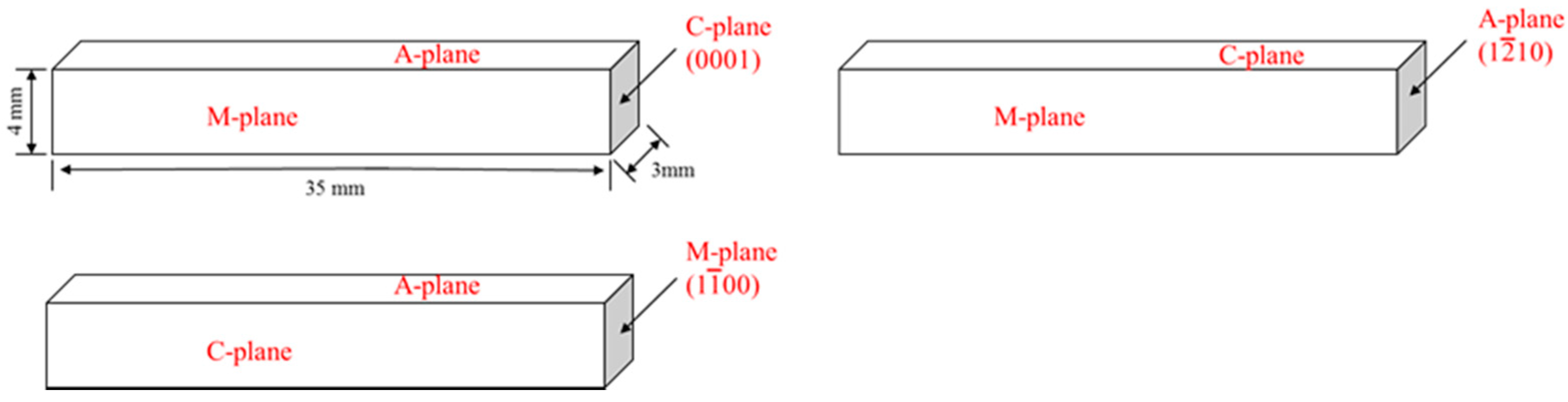
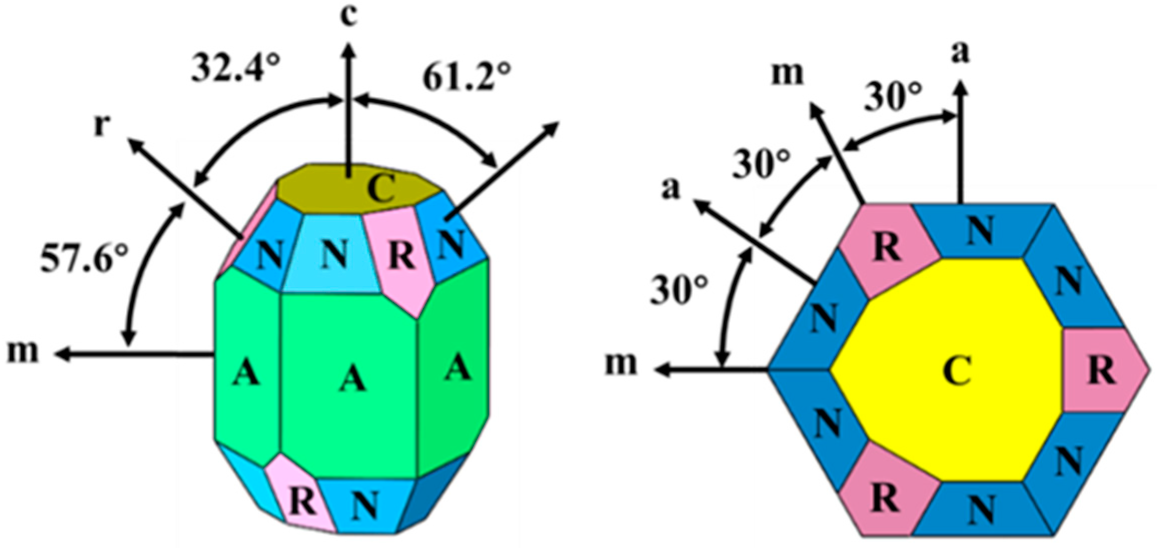
2.1. Sample Preparation and Orientation
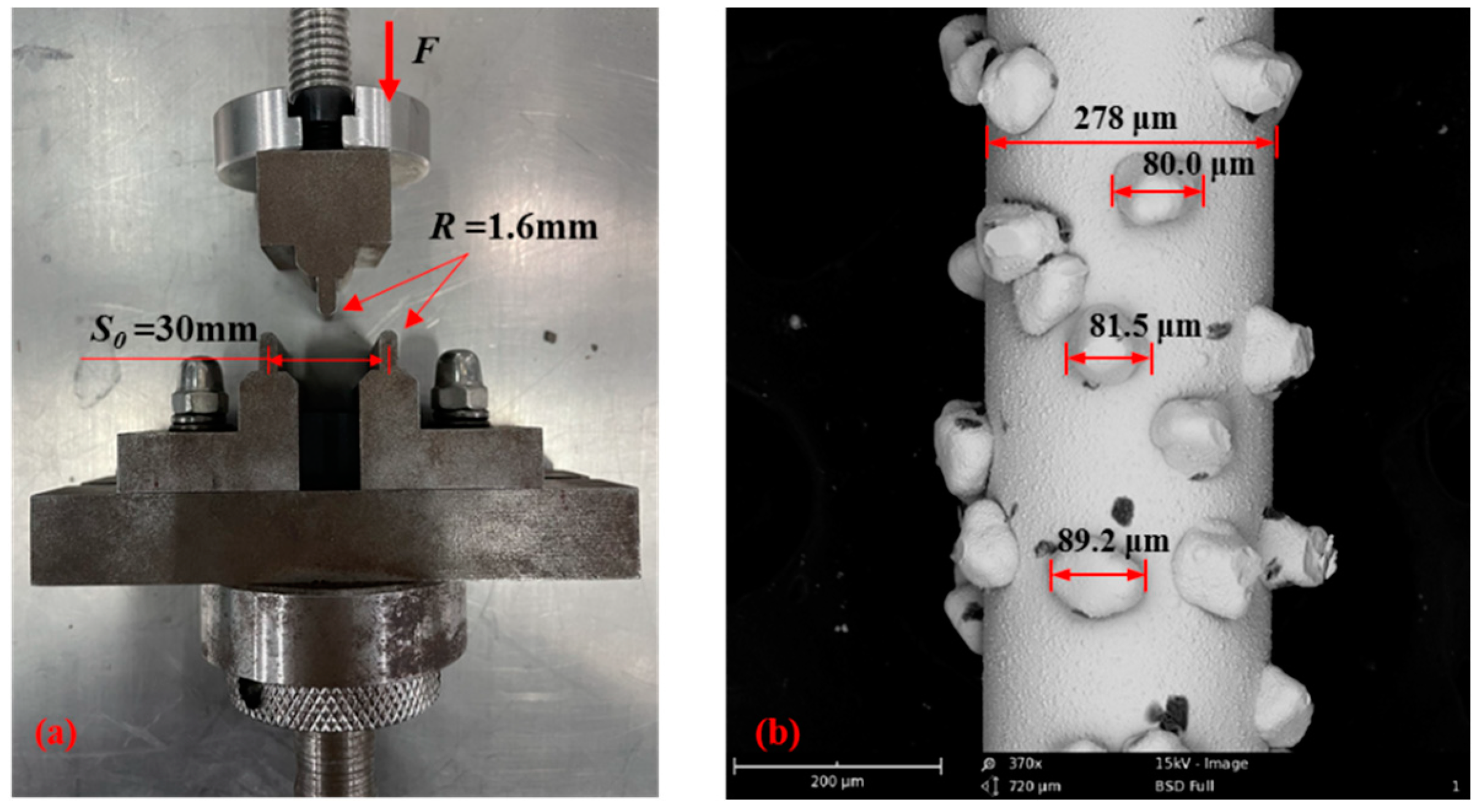
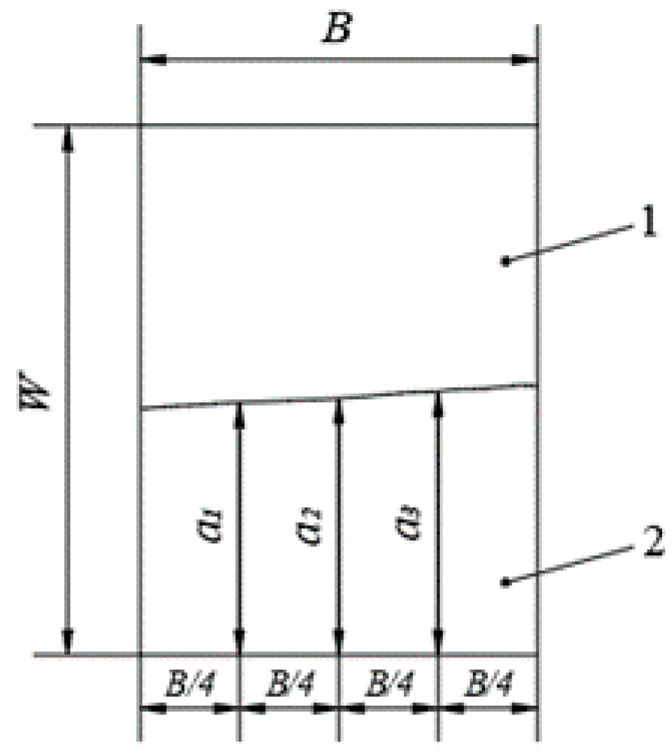
2.2. Three-Point Bending Test and SEVNB
3. Results and Discussion
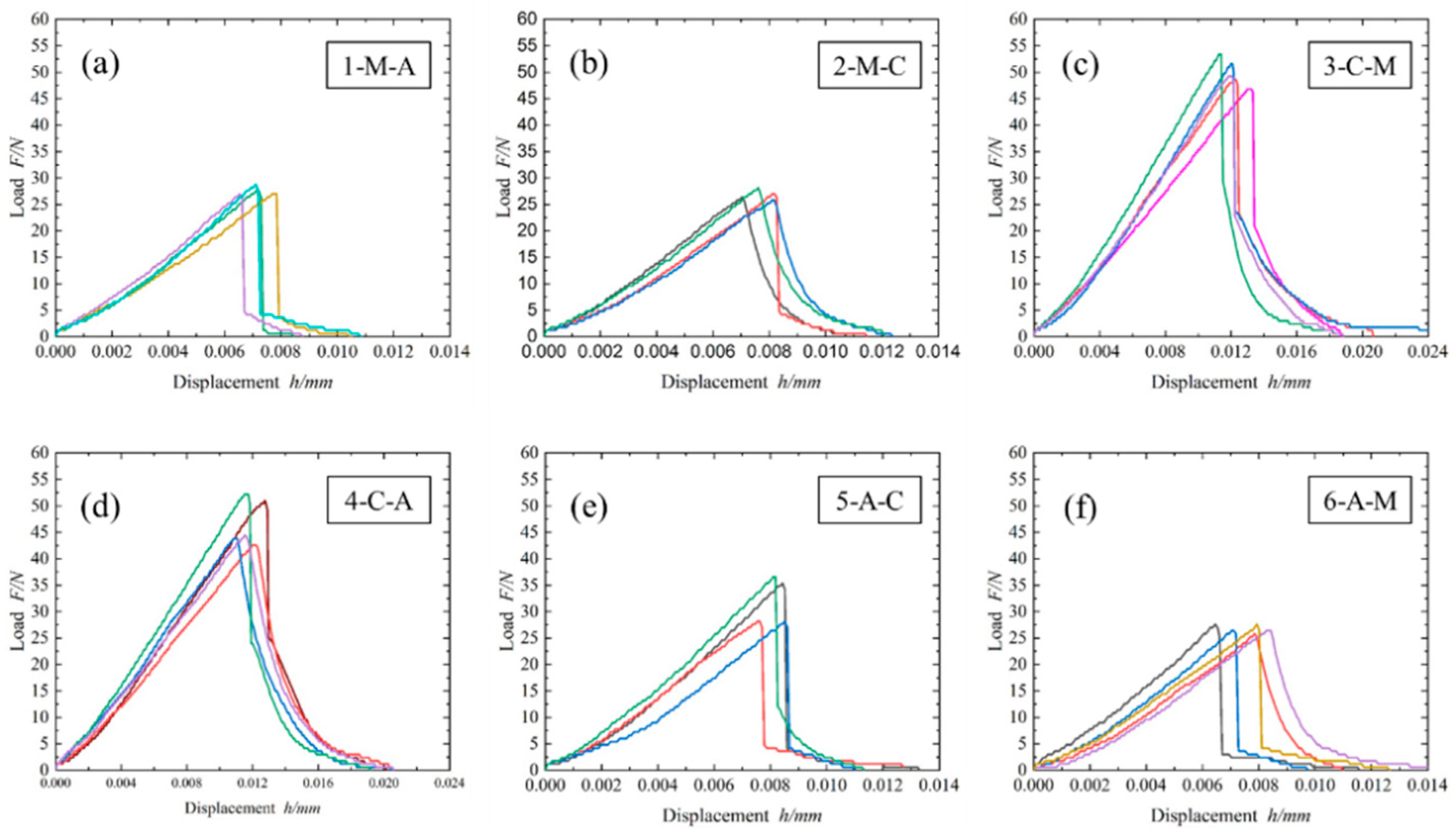
3.1. Displace-Loading Curves
3.2. Calculation of K1C
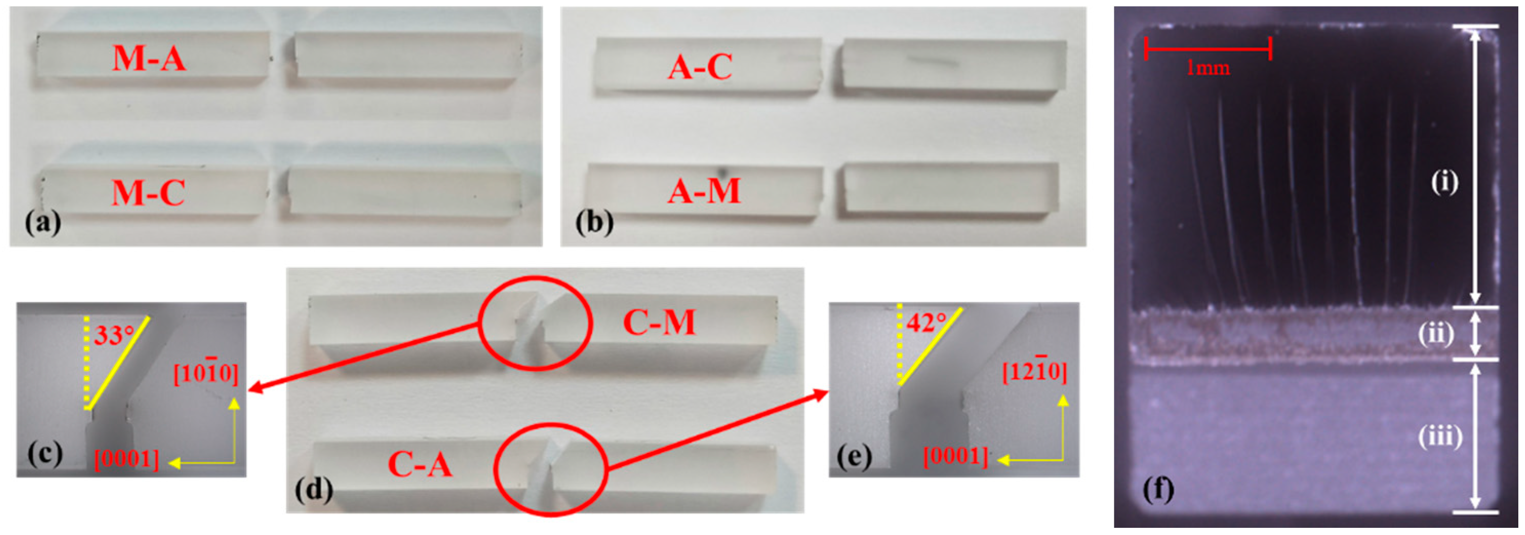
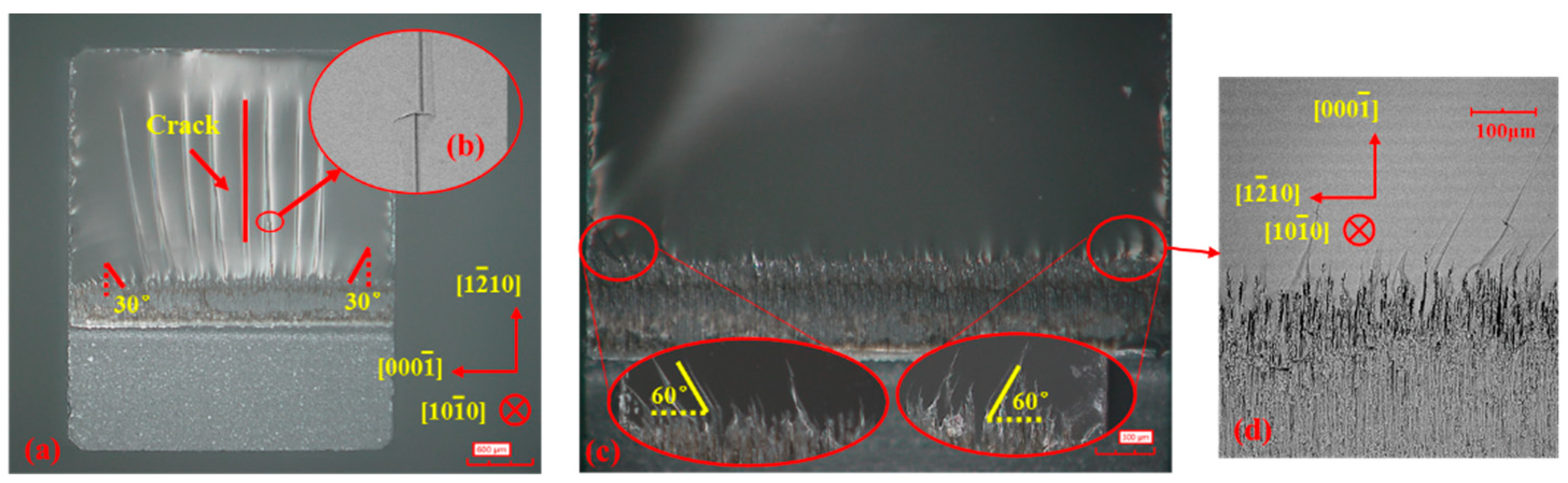
3.3. Morphology of the Fractured Surface
3.4. Roughness of the Fractured Surface
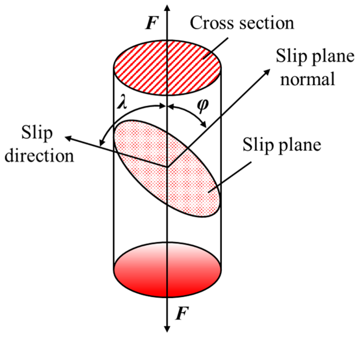
4. The Critical Resolved Shear Stress for Fracture Opening
5. Conclusions
- (1)
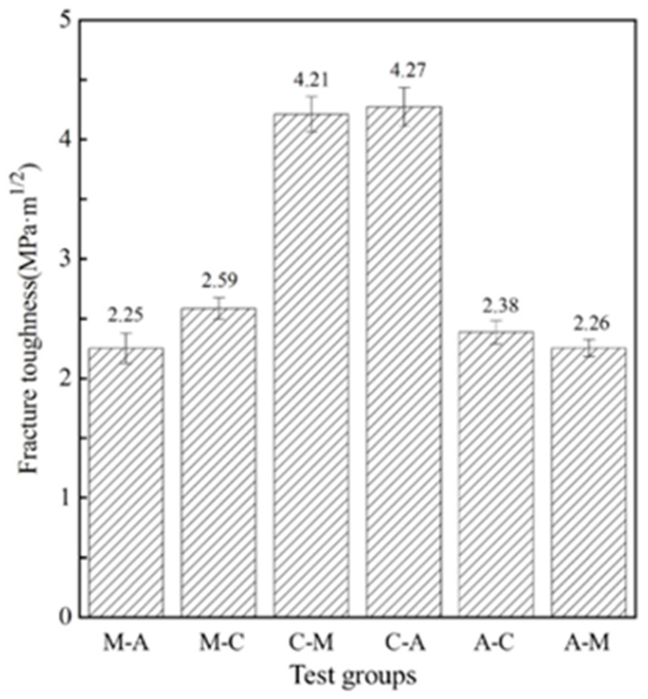
- The fracture toughness of single-crystal sapphire with different crystal planes showed anisotropy. The fracture toughness of C-plane sapphire was highest than other orientations. Fracture toughness of different crystal planes decreases in the order of C-plane > M-plane > A-plane.
- (2)
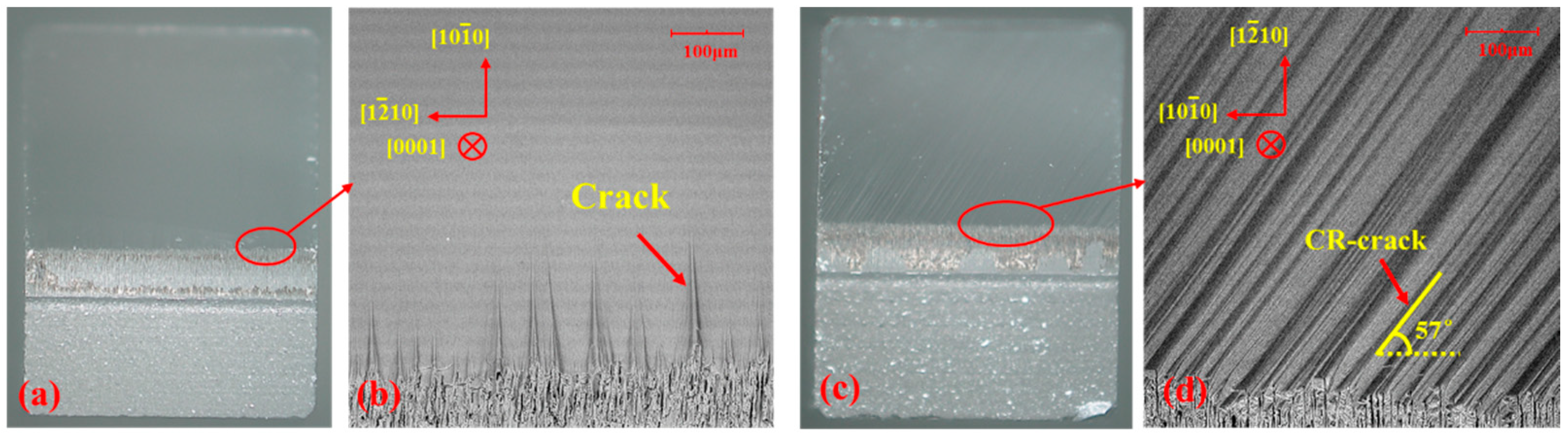
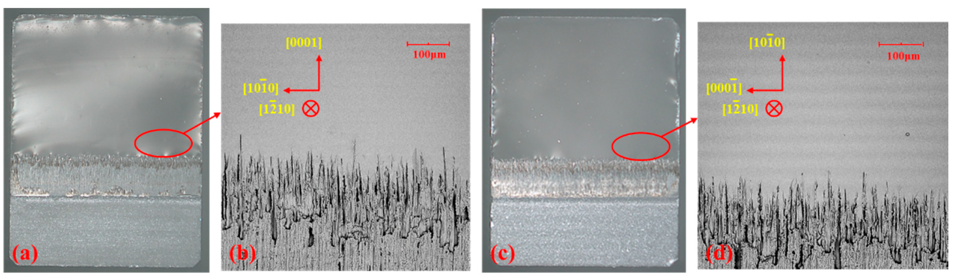
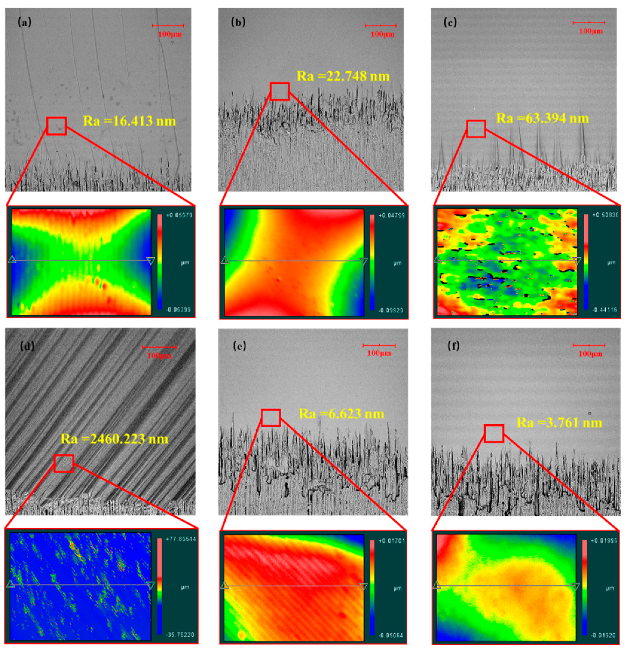
- The fracture morphology of single-crystal sapphire with different crystal faces shows obvious anisotropy, different cracks growth, and morphology. In M-plane sapphire, there are many long cracks on the fracture when loading A-plane. In C-plane sapphire, the whole fracture presents inclined cracks with 57 degrees when loading A-plane. The fracture surfaces of other samples are smooth. The roughness of different crystal planes decreased in the order of C-plane > M-plane > A-plane, the same as the order of fracture toughness. The surface roughness will affect the dissipation of fracture energy. With a larger the fracture toughness value, the ability of sapphire to resist fracture is stronger.
- (3)
- C-plane sapphire cleavages along the R-plane with an angle of 57.6 degrees. M-plane and A-plane sapphire cleavages along their cross-section. The cleavage fracture of C-plane sapphire seems to be related to the rhombohedral twin. The rhombohedral twin promotes crack propagation and forms the fracture morphology of inclined cracks.
Author Contributions
Funding
Data Availability Statement
Conflicts of Interest
References
- Salem, J.A.; Quinn, G.D. Fractographic analysis of large single crystal sapphire refractive secondary concentrators. J. Eur. Ceram. Soc. 2014, 34, 3271–3281. [Google Scholar] [CrossRef]
- Khattak, C.P.; Shetty, R.; Schwerdtfeger, C.R.; Ullal, S. World’s largest sapphire for many applications. J. Cryst. Growth 2016, 452, 44–48. [Google Scholar] [CrossRef]
- Huang, H.; Li, X.; Mu, D.; Lawn, B.R. Science and art of ductile grinding of brittle solids. Int. J. Mach. Tools Manuf. 2020, 161, 103675. [Google Scholar] [CrossRef]
- Bao, Y.; Zhou, Y. A new method for precracking beam for fracture toughness experiments. J. Am. Ceram. Soc. 2006, 89, 1118–1121. [Google Scholar] [CrossRef]
- Sakai, M.; Bradt, R.C. Fracture toughness testing of brittle materials. Int. Mater. Rev. 1993, 38, 53–78. [Google Scholar] [CrossRef]
- Wan, D.; Wei, Y.; Bao, Y.; Tian, Y. Comparison and Analysis of the Accuracy and Convenience of Ceramic Fracture Toughness Testing Methods. J. Chin. Ceram. Soc. 2019, 47, 1080–1088. [Google Scholar]
- Zhao, W.; Rao, P.; Ling, Z. A new method for the preparation of ultra-sharp V-notches to measure fracture toughness in ceramics. J. Eur. Ceram. Soc. 2014, 34, 4059–4062. [Google Scholar] [CrossRef]
- Quinn, G.D.; Swab, J.J. Fracture toughness of glasses as measured by the SCF and SEPB methods. J. Eur. Ceram. Soc. 2017, 37, 4243–4257. [Google Scholar] [CrossRef]
- Yanaba, Y.; Hayashi, K. Relation between fracture surface area of a flexural strength specimen and fracture toughness for WC-10mass% Co cemented carbide and Si3N4 ceramics. Mater. Sci. Eng. A 1996, 209, 169–174. [Google Scholar] [CrossRef]
- Zhao, Q.; Wang, Y.; Yu, G.; Dong, S.; Zhang, X. Investigation of anisotropic mechanisms in ultra-precision diamond machining of KDP crystal. J. Mater. Process. Technol. 2009, 209, 4169–4177. [Google Scholar] [CrossRef]
- Wen, Q.; Wei, X.; Jiang, F.; Lu, J.; Xu, X. Focused Ion Beam Milling of Single-Crystal Sapphire with A-, C-, and M-Orientations. Materials 2020, 13, 2871. [Google Scholar] [CrossRef] [PubMed]
- Wen, Q.; Zhang, P.; Cheng, G.; Jiang, F.; Lu, X. Crystalline orientation effects on material removal of sapphire by femtosecond laser irradiation. Ceram. Int. 2019, 45, 23501–23508. [Google Scholar] [CrossRef]
- Wang, L.; Hu, Z.; Chen, Y.; Yu, Y.; Xu, X. Material removal mechanism of sapphire substrates with four crystal orientations by double-sided planetary grinding. Ceram. Int. 2020, 46, 7813–7822. [Google Scholar] [CrossRef]
- Luo, Q.; Lu, J.; Xu, X.; Jiang, F. Removal mechanism of sapphire substrates (0001, 11-20 and 10-10) in mechanical planarization machining. Ceram. Int. 2017, 43, 16178–16184. [Google Scholar] [CrossRef]
- Wang, N.; Jiang, F.; Xu, X.; Duan, N.; Wen, Q.; Lu, X. Research on the machinability of A-plane sapphire under diamond wire sawing in different sawing directions. Ceram. Int. 2019, 45, 10310–10320. [Google Scholar] [CrossRef]
- Luan, X.; Jiang, F.; Wang, N.; Xu, X.; Lu, X.; Wen, Q. The mechanical response characteristics of sapphire under dynamic and quasi-static indentation loading. Ceram. Int. 2018, 44, 15208–15218. [Google Scholar] [CrossRef]
- Jiang, F.; Luan, X.; Wang, N.; Xu, X.; Lu, X.; Wen, Q. Research on the dynamic mechanical properties of C-plane sapphire under impact loading. Ceram. Int. 2018, 44, 9839–9847. [Google Scholar] [CrossRef]
- Wang, N.; Jiang, F.; Xu, X.; Lu, X. Effects of crystal orientation on the crack propagation of sapphire by sequential indentation testing. Crystals 2018, 8, 3. [Google Scholar] [CrossRef] [Green Version]
- Wang, K.; Jiang, F.; Yan, L.; Xu, X.; Wang, N.; Zha, X.; Lu, X.; Wen, Q. Study on mechanism of crack propagation of sapphire single crystals of four different orientations under impact load and static load. Ceram. Int. 2019, 45, 7359–7375. [Google Scholar] [CrossRef]
- Wan, L.; Dai, P.; Li, L.; Deng, Z.; Hu, Y. Investigation on ultra-precision lapping of A-plane and C-plane sapphires. Ceram. Int. 2019, 45, 12106–12112. [Google Scholar] [CrossRef]
- Wang, K.; Jiang, F.; Li, Y.; Wang, N.; Hu, Z.; Yan, L.; Lu, J.; Wen, Q.; Lu, X. Prediction of pop-in load for sapphires with different crystal orientations. Ceram. Int. 2020, 46, 6682–6692. [Google Scholar] [CrossRef]
- Lin, J.; Jiang, F.; Xu, X.; Lu, J.; Tian, Z.; Wen, Q.; Lu, X. Molecular dynamics simulation of nanoindentation on c-plane sapphire. Mech. Mater. 2021, 154, 103716. [Google Scholar] [CrossRef]
- Lin, J.; Jiang, F.; Wen, Q.; Wu, Y.; Lu, J.; Tian, Z.; Wang, N. Deformation anisotropy of nano-scratching on C-plane of sapphire: A molecular dynamics study and experiment. Appl. Surf. Sci. 2021, 546, 149091. [Google Scholar] [CrossRef]
- Azhdari, A.; Nemat-Nasser, S.; Rome, J. Experimental observations and computational modeling of fracturing in an anisotropic brittle crystal (sapphire). Int. J. Fract. 1998, 94, 251–266. [Google Scholar] [CrossRef]
- Konstantiniuk, F.; Tkadletz, M.; Kainz, C.; Czettl, C.; Schalk, N. Mechanical properties of single and polycrystalline α-Al2O3 coatings grown by chemical vapor deposition. Surf. Coat. Technol. 2021, 410, 126959. [Google Scholar] [CrossRef]
- Graça, S.; Trabadelo, V.; Neels, A.; Kuebler, J.; Le Nader, V.; Gamez, G.; Döbeli, M.; Wasmer, K. Influence of mosaicity on the fracture behavior of sapphire. Acta Mater. 2014, 67, 67–80. [Google Scholar] [CrossRef]
- Dobrovinskaya, E.R.; Lytvynov, L.A.; Pishchik, V. Sapphire: Material, Manufacturing, Applications; Springer: New York, NY, USA, 2009. [Google Scholar]
- Nowak, R.; Sakai, M. The Anisotropy of Surface Deformation of Sapphire: Continuous Indentation of Triangular Indenter. Acta Metall. Et Mater. 1994, 42, 2879–2891. [Google Scholar] [CrossRef]
- Guan, Z.; Zhang, Z.; Jiao, J. Physical Properties of Inorganic Materials; Tsinghua University Press: Beijing, China, 2004. [Google Scholar]
- Nose, T.; FUJII, T. Evaluation of fracture toughness for ceramic materials by a single-edge-precracked-beam method. J. Am. Ceram. Soc. 1988, 71, 328–333. [Google Scholar] [CrossRef]
- Dukino, R.D.; Swain, M.V. Comparative measurement of indentation fracture toughness with Berkovich and Vickers indenters. J. Am. Ceram. Soc. 1992, 75, 3299–3304. [Google Scholar] [CrossRef]
- Fischer, H.; Waindich, A.; Telle, R. Influence of preparation of ceramic SEVNB specimens on fracture toughness testing results. Dent. Mater. 2008, 24, 618–622. [Google Scholar] [CrossRef] [PubMed]
- ISO 23146: Fine Ceramics (Advanced Ceramics, Advanced Technical Ceramics)—Test Method for Fracture Toughness of Monolithic Ceramics-Single-Edge V-Notch Beam (SEVNB) Method; ISO: Geneva, Switzerland, 2012.
- Wiederhorn, S.M.; Hockey, B.J.; Roberts, D.E. Effect of temperature on the fracture of sapphire. Philos. Mag. A J. Theor. Exp. Appl. Phys. 1973, 28, 783–796. [Google Scholar] [CrossRef]
- Swain, M.V.; Lawn, B.R.; Burns, S.J. Cleavage step deformation in brittle solids. J. Mater. Sci. 1974, 9, 175–183. [Google Scholar] [CrossRef]
- Zhang, T.; Jiang, F.; Huang, H.; Lu, J.; Xu, X. Towards understanding the brittle-ductile transition in the extreme manufacturing. Int. J. Extrem. Manuf. 2021, 3, 022001. [Google Scholar] [CrossRef]
- Mizumoto, Y.; Maas, P.; Kakinuma, Y.; Min, S. Investigation of the cutting mechanisms and the anisotropic ductility of monocrystalline sapphire. CIRP Ann.—Manuf. Technol. 2017, 66, 89–92. [Google Scholar] [CrossRef]
- Schmid, E.; Boas, W. Plasticity of Crystals; FA Hughes & Co, Ltd.: London, UK, 1950. [Google Scholar]


| Number | Twin & Slip Systems | Plastic Deformation Type | Critical Resolved Shear Stress (GPa) |
|---|---|---|---|
| 1 | <01-11> {01-12} | Rhombohedral twin (RT) | 0.111 |
| 2 | <1-100> {0001} | Basal twin (BT) | 0.148 |
| 3 | <2-1-10> {01-12} | Rhombohedral slip (RS) | 3 |
| 4 | <2-1-10> {0001} | Basal slip (BS) | 17 |
| 5 | <1-210> {10-10} | Prismatic slip (PRS) | 1.2 |
| Steps | Machine | Parameter | Result |
|---|---|---|---|
| Step 1: Preparing the U-notch groove | Diamond wire cutting machine of Shenyang kejing STX-402 | Vc = 1.8 m/s Vf = 0.3 mm/min ap = 2 mm | 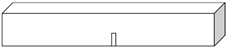 |
| Step 2: Preparing the V-notch | Laser machine of SCABNLAB BasiCube10 SN:545393 | λ= 355 nm τ = 15 ns Vs = 1 mm/s f = 50 kHz d = 10 μm n = 10 | 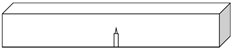 |
| Test Groups | Cross-Section | Loaded Surface | Test Groups | Cross-Section | Loaded Surface |
|---|---|---|---|---|---|
| 1 | M | A | 4 | C | A |
| 2 | M | C | 5 | A | C |
| 3 | C | M | 6 | A | M |
| Test Groups | K1C-1 | K1C-2 | K1C-3 | K1C-4 | K1C-5 | K1C-6 | K1C-7 | Average K1C | |
|---|---|---|---|---|---|---|---|---|---|
| 1-M-A | 2.39 | 2.03 | 2.35 | 2.22 | 2.21 | 2.19 | 2.36 | 2.25 | 2.42 |
| 2-M-C | 2.47 | 2.60 | 2.56 | 2.67 | 3.10 * | 2.70 | 2.51 | 2.59 | |
| 3-C-M | 4.04 | 4.26 | 4.45 | 4.44 * | 4.27 | 4.13 | 4.12 | 4.21 | 4.24 |
| 4-C-A | 4.37 | 4.36 | 4.28 | 2.53 * | 4.30 | 3.95 | 4.36 | 4.27 | |
| 5-A-C | 2.39 | 2.51 | 2.37 | 2.58 * | 2.47 * | 2.41 | 2.24 | 2.38 | 2.32 |
| 6-A-M | 2.28 | 2.17 | 2.19 | 2.34 | 2.23 | 2.62 * | 2.32 | 2.26 | |
| Sample | Loaded Surface | Cleavage Direction | Morphology of the Fractured Surface |
|---|---|---|---|
| M-Plane sapphire | A-plane | a-direction | Long large cracks with small transverse steps |
| M-Plane sapphire | C-plane | c-direction | Flat and smooth with short crack growth |
| C-Plane sapphire | M-plane | r-direction | Flat with thick and short triangular cracks |
| C-Plane sapphire | A-plane | r-direction | Very rough surface with 57° cracks |
| A-Plane sapphire | C-plane | c-direction | Flat and smooth without cracks |
| A-Plane sapphire | M-plane | m-direction | Flat and smooth without cracks |
| Sample | K1C (MPa·m1/2) | r (mm) | σa (MPa) | Plastic Deformation | CRSS (GPa) | φ (°) | λ (°) | m | τ (GPa) | Activation |
|---|---|---|---|---|---|---|---|---|---|---|
| Slip/Twin | Slip/Twin | |||||||||
| M-plane sapphire | 2.42 | 0.5 | 193 | Rhombohedral plane | 3/0.111 | 57.6 | 32.4 | 0.45 | 0.087 | N/N |
| Basal plane | 17/0.148 | 0 | 90 | 0 | 0 | N/N | ||||
| Prism plane | 1.2/- | 90 | 0 | 0 | 0 | N/- | ||||
| C-plane sapphire | 4.24 | 0.5 | 338 | Rhombohedral plane | 3/0.111 | 32.4 | 57.6 | 0.45 | 0.152 | N/Y |
| Basal plane | 17/0.148 | 90 | 0 | 0 | 0 | N/N | ||||
| Prism plane | 1.2/- | 0 | 90 | 0 | 0 | N/- | ||||
| A-plane sapphire | 2.32 | 0.5 | 185 | Rhombohedral plane | 3/0.111 | 57.6 | 32.4 | 0.45 | 0.083 | N/N |
| Basal plane | 17/0.148 | 0 | 90 | 0 | 0 | N/N | ||||
| Prism plane | 1.2/- | 90 | 0 | 0 | 0 | N/- |
Publisher’s Note: MDPI stays neutral with regard to jurisdictional claims in published maps and institutional affiliations. |
© 2021 by the authors. Licensee MDPI, Basel, Switzerland. This article is an open access article distributed under the terms and conditions of the Creative Commons Attribution (CC BY) license (https://creativecommons.org/licenses/by/4.0/).
Share and Cite
Huang, S.; Lin, J.; Wang, N.; Guo, B.; Jiang, F.; Wen, Q.; Lu, X. Fracture Behavior of Single-Crystal Sapphire in Different Crystal Orientations. Crystals 2021, 11, 930. https://doi.org/10.3390/cryst11080930
Huang S, Lin J, Wang N, Guo B, Jiang F, Wen Q, Lu X. Fracture Behavior of Single-Crystal Sapphire in Different Crystal Orientations. Crystals. 2021; 11(8):930. https://doi.org/10.3390/cryst11080930
Chicago/Turabian StyleHuang, Shizhan, Jiaming Lin, Ningchang Wang, Bicheng Guo, Feng Jiang, Qiuling Wen, and Xizhao Lu. 2021. "Fracture Behavior of Single-Crystal Sapphire in Different Crystal Orientations" Crystals 11, no. 8: 930. https://doi.org/10.3390/cryst11080930
APA StyleHuang, S., Lin, J., Wang, N., Guo, B., Jiang, F., Wen, Q., & Lu, X. (2021). Fracture Behavior of Single-Crystal Sapphire in Different Crystal Orientations. Crystals, 11(8), 930. https://doi.org/10.3390/cryst11080930